1
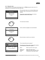
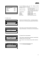
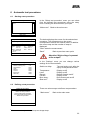
User Manual
frida
Portable VLF High Voltage Testing Device
Ref. No. 822-125
10/2006
BAUR Prüf- und Messtechnik GmbH
Raiffeisenstrasse 8, A-6832 Sulz/Austria
e-mail: [email protected]
Internet: www.baur.at
Tel. +43/5522/4941-0
Fax +43/5522/4941-3
Symbols in this user manual
To find the important information quickly the
appropriate passages of text are marked with
symbols (any symbols not listed here are selfexplanatory).
Additional and special information (literature etc.) on
the relevant subject are available from BAUR.
Important information about the device!
You must read it!
This text contains important information
Copyright
© BAUR Prüf- und Messtechnik GmbH,
A-6832-Sulz / Austria.
All rights reserved.
No part of this publication may in any way or form
be reproduced, transmitted, communicated, stored
in a computer system or translated into another
language without the written permission of BAUR
Sulz / Austria.
We reserve the right in the interests of our
customers to make amendments as a result of
further
technical
development.
Illustrations,
descriptions and scope of supply are therefore not
binding.
The names of products and companies are the
trademarks or brand names of the relevant
companies.
Preface
This manual contains all the necessary information
about the correct use of the described devices.
Please read this manual carefully before you use
the devices.
BAUR Prüf- und Messtechnik GmbH,
Raiffeisenstrasse 8, A-6832 Sulz / Austria
Tel.
Fax
+43/5522/4941-0
+43/5522/4941-3
e-mail: mailto:[email protected]
Internet: www.baur.at
or contact your nearest BAUR representative.
2
Safety advice
The system has been manufactured to the current
state of technology and is safe to operate. The
individual parts and the finished devices are
continuously tested within the scope of our quality
assurance measures by our qualified personnel..
Every device is fully tested before delivery. Every
person who deals with the connection, bringing into
use, operation or maintenance of the product must
have read and understood the complete user
manual. The operating company must therefore
ensure that only authorised persons work with the
system. The operating person is obliged to report
immediately any changes occurring in the device
that detrimentally affect safety.
Proper use
frida is used to test high voltage cables and rotating
machines. Any other use or use exceeding the
above shall be considered improper use. The
manufacturer will not be liable for the resulting
damages. The risk is carried solely by the user. In
every case the local safety and accident prevention
legislation shall apply to the operation of the system.
Warranty
We are obliged - on the written request of the
purchaser - as quickly as possible to make good or
replace, as decided by us, all parts that can be
shown to have become defective or unusable as a
result of poor materials, defective design or faulty
construction. We will bear only the cost of the repair
and the parts replaced. Transport to us and back to
you, packaging and insurance shall be at the cost of
the purchaser. The period of warranty is
12 months from the date of delivery. We accept no
liability for damage arising from normal wear,
improper handling or non-observance of the
instructions for use or safety advice! We refuse to
accept any liability if the purchaser himself or a third
party carries out repairs or modifications to the
device! Transport damage and wear parts e.g. fuses
are not covered by the warranty!
In addition we refer you to the "General Conditions
of Sale and Supply" of:
BAUR Prüf- und Messtechnik GmbH,
Raiffeisenstrasse 8
A-6832-Sulz / Austria
3
Table of contents
1
2
3
4
5
6
7
8
9
10
Use
1.1 Cable testing
1.2 Cable sheath testing
1.3 Cable sheath fault location
Features
Operating controls
3.1 High voltage operating control unit
3.2 Connection panel right side
3.3 Connection panel left side
3.4 Menu navigation
3.5 Voltage and current display
Bringing into use
4.1 Important basic rules
4.2 Discharge and earth rod
4.3 Preparing the device for cable testing
4.4 Switching high voltage on and off
4.5 Load determination
4.6 Using the menu
Manual testing
5.1 VLF sinus auto
5.2 VLF sinus
5.3 DC
5.4 Square auto
5.5 Square
Automatic test procedures
6.1 Starting a test procedure
6.2 Defining a test procedure
6.2.1 Defining a new test procedure
6.2.2 Amending existing test procedures
6.2.3 Copying and amending a test procedure
6.2.4 Deleting a test procedure
Extras - device settings
7.1 Extras
7.2 Info
7.3 Language
7.4 Time & date
7.5 Settings
7.6 Updating
Technical data
8.1 General technical data
8.2 Load diagram
Maintenance
9.1 Servicing
9.2 Error messages
9.3 Cleaning
Accessories, options and spare parts
10.1 Delivery includes
10.2 Optional accessories
10.3 Replacement parts
5
5
7
7
8
9
9
9
9
9
9
10
10
10
11
13
14
15
16
16
18
19
20
21
22
22
22
23
24
24
24
25
25
25
25
25
26
26
27
27
28
29
29
29
29
30
30
30
30
.
4
1 Use
The frida high voltage test generator is used for the testing of medium
voltage cables with extruded insulation in accordance with VDE DIN 0276-620
(CENELEC HD 620) and IEEE P400.2, for impregnated paper insulation in
accordance with VDE DIN 0276-621 (CENELEC HD 621) and IEEE Std 4002001 and other high voltage insulation up to 23 kVrms. VLF (very low
frequency) testing allows insulation damage to be detected in the shortest
possible testing time and does not detrimentally affect the quality of the
insulation material. Furthermore with frida you can carry out DC testing up to
+/-30 kV. The device also allows a square wave voltage of +/- 30 kV with an
adjustable slew rate to be created. The frequency of the created alternating
voltage can be varied within the range 0.01 Hz to 0.1 Hz to extend the load
range, either manually or automatically. The device also has a preset mode for
cable sheath fault testing and location.
1.1 Cable testing
The use of oiled paper and mass impregnated cables in energy transmission by plastic
cables has required changes in cable testing procedures. The DC test procedure used
successfully for decades for paper-insulated mass impregnated cables proved unsuitable for
the testing of plastic cables. On the one hand serious faults were seldom detected whilst on
the other hand the use of DC tests led to the build-up of long-lasting space charges. These
space charges can lead to the insulation strength being exceeded locally when the operating
AC voltage is applied and to the formation of electrical trees. The insulation is irreversibly
damaged by this and complete breakdown is only a matter of time. Something that countless
failures of plastic insulated cables after successful DC testing confirm. For this reason the
industry has been searching for several years for a new way of testing plastic cables. Testing
at very low frequency (VLF), which is also suitable for mass cables, has replaced DC testing
in practice. In terms of official standards, the 0.1 Hz high voltage test has been accepted as
an alternative testing technique to DC testing in the European harmonisation document
CENELEC HD 620 S1 for plastic-insulated and in HD 621 S1 for oiled and mass
impregnated cables.
5
Page 5-C-16
E DIN VDE 0276-620 (VDE 0276 Part 620):2000-12
Recommended tests after cable installation, if required
Tests
Voltage test on the
insulation 1) 2)
Test AC voltage 45 to 65 Hz
- Testing level (effective value)
- Duration of test
Alternative:
Test AC voltage 0.1 Hz
- Testing level (effective value)
- Duration of test
Test for intactness of the plastic
outer sheath on installed cables
1
1.1
1.2
2
1)
2)
Requirements
2 Uo
60 min
3 Uo
60 min
Test procedure
No breakdown
No breakdown
It is recommended not to exceed a
voltage of 3 kV or 5 kV respectively
when using DC voltage for PVC or PE
sheaths. The information on any
damage to a cable sheath normally
appears within one minute.
The test levels and durations are given as preferred values and have been
determined based on the currently available experience of labour and networks.
If the cable ends in a transformer or in sealed switchgear then this test requires the
customer to obtain the agreement of the manufacturer of the transformer or the
switchgear.
6
1.2 Cable sheath testing
Cable sheath testing is carried out in order to detect damage to cable sheaths. To do this a
DC test is carried out in accordance with the applicable standard (see table above).
1.3
Cable sheath fault location
frida can be used in combination with a step voltage meter (e.g. UL) to pin-point the location
of cable sheath faults. To do this a cyclical voltage is applied in accordance with the diagram
below. The damage to the cable sheath can then be pin-pointed with the step voltage meter.
0,8 s
0,8 s
1,2 s
0,8 s
1,2 s
0,8 s
3,5 s
...
Time
-U
7
2 Features
An important advantage of the device is its portability, especially when used on site. The
compact design means that the device can also be carried within the site. Testing in bad
weather is not problem as the equipment is completely protected against splash water. A
graphics display with a menu for all control functions ensures ease and simplicity of
operation. User-defined test sequences (e.g. incremental voltage testing) can be defined in
order to set up an automatic test procedure. All test records can be read out and printed from
the USB memory stick.
•
•
•
•
•
•
Fully automatic test procedure in accordance with VDE DIN 0276-620, IEEE P400.2,
VDE DIN 0276-621 and IEEE 400-2001
Input power only 350 W
Short-circuit proof
Timer function with automatic switch-off device
Easy transportable
Menu-guided in different languages
Safety equipment
•
•
•
•
Constructed in accordance with VDE DIN 0104, EN 50191
Switch-on interlock for high voltage, zero interlock
Emergency-off switch
Status display of all important safety functions
Operating modes
Automatic test procedures and manual tests:
• VLF test at 0.1 Hz
• VLF test with automatic frequency selection
• DC voltage test
• Square-wave voltage test
• Square-wave voltage test with automatic frequency selection
• Cable sheath fault location
8
3 Operating controls
3.1
High voltage operating control unit
Main menu
Press the READY key
6)
5)
3)
2)
Menu
1)
1)
2)
3)
4)
5)
6)
7)
7)
4)
For switching frida on and off
High voltage (HV) ready / on / off
Displays of menus and readings
Navigation and confirm button (press)
Attention – red light = HV on
Data exchange by USB memory stick
Switches off the high voltage
Main switch
HV keys
Display
Rotary knob
Status indicator high voltage
USB socket
Emergency – off
3.2
Connection panel right side
1) Network connection
2) Ground line
3.3
Connection panel left side
1) External emergency-off plug/socket
3.4 Menu navigation
Selecting the fields in the toolbar:
Turn the rotary knob to move the selection highlighting over the fields. To select press the
rotary knob.
3.5 Voltage and current display
Different values are used for display and input depending on the selected voltage shape:
Voltage - set
Voltage - display
Current - display
Sinus
Effective
Effective
Effective
DC
Transient
Transient
Transient
Square
Peak
Peak
Leakage
Sheath fault location
Peak
Transient
Transient
9
4 Bringing into use
4.1
Important basic rules
frida is used to test disconnected lengths of cable. Before connecting the device to the cable
length to be tested you must therefore ensure that the cable is disconnected and
deenergised. Observe the statutory and operational safety regulations!
Never operate the device in a potentially explosive atmosphere.
Before every contact with the object to be tested it must be discharged and
earthed by means of a discharge/earth rod. It must remain earthed whilst you are
working on the object.
4.2
Discharge and earth rod
The protective ground cable of the discharge and earth rod must be connected to the station
ground. The discharge resistance of the combined discharge and earth rod can be shortcircuited to earth the object under test:
Discharge rod
Earth rod
The object under test is discharged by the frida VLF generator after proper completion of a
test. Before any contact with the object under test it must be earthed. There may still be
voltage at the object under test after a breakdown in the cable or after an interruption in
measurement (e.g. by pressing the emergency-off button) and therefore it must first be
completely discharged and then earthed before any contact is made.
For proper discharge and/or earthing, the protective ground cable of the rod must
be solidly connected to the station ground or protective ground. Touch the rod
only by its handle when discharging and/or earthing the rod. The minimum
discharge time stipulated on the discharge rod must be observed when
discharging it.
10
4.3
Preparing the device for cable testing
Preparing the cable
Disconnect the object under test on all contacts, secure against it being switched on again
and check that it is deenergised. Isolate adjacent live parts. It must be ensured that when
high voltage is applied there can be no arcing or breakdown to the adjacent parts of the
station or the cabling. In the case of multi-wire objects under test, all wires, except for the
ones being tested, must be connected to the station ground. Clean the terminals if
necessary.
Connecting the protective ground cable
Connect frida with the supplied protective ground cable (yellow-green) at the protective
ground connector (connection panel) to the station protective ground. A screw terminal is
provided on the protective ground cable for this.
Connecting the high voltage feed cable
Connect the shielding connector of the high voltage feed cable to the earthed sheath of the
cable under test. Connect the high voltage connector with the centre conductor of the cable
under test. A crocodile clip is attached to the high voltage feed cable for this.
Please observe the advice about discharging and earthing and the general safety
regulations.
frid a
Centre
conductor
Terminal
Shielding
Station- and
protective
ground
11
Connecting to various cable types
Connecting to a 3-phase
shielded cable
Connecting to a 1-phase
shielded cable
Connecting to a 3-phase
unshielded cable
12
4.4
Switching high voltage on and off
High voltage may be switched on and off on the frida testing device using the three keys to
the left of the display. The yellow background illumination indicates which key needs to be
pressed for the next step. A flashing or illuminated HV light indicates the system status.
High voltage can also be enabled later, but no later than the start of a test. High voltage is
not necessary for making the system settings or for entering test procedures.
Ready for operation
Switching on the main switch places the device in
the “Ready for operation” state. This state is
indicated by the illumination of the green light.
Enable high voltage
Press the READY key
Press the yellow-highlighted key for a minimum of
1 second.
Menu
High voltage ready to switch on
Displayed by a red flashing warning light
(6 seconds)
Enable high voltage
Press the ON key
To set the device “In operation” the key must be
pressed within the period that the light is flashing. If
the key is not pressed within this time the device
reverts to the “Ready for operation” state.
Menu
In operation
Main menu
Manual testing
Load settings from last measurement
Start test procedure
Define test procedure
Cable sheath fault
Extras
Operation is indicated by the red illuminated
warning light.
On switching on, frida displays main menu.
Attention! In the Operation state it must
be assumed that high voltage is present
at the output!
Date.........Time
13
Switching off
After completing the cable testing:
−
−
Press this key.
This key activates the discharge device, which
discharges the cable and the internal capacitor
through resistances. The device is once more in the
“Ready for operation” state
For safety reasons the high voltage connection must be
earthed before making any contact. (The BAUR discharge and
earth rod is used for this)
Emergency – off
4.5
After activating the emergency-off switch frida returns to
the “Ready for operation” state. The emergency-off
message must be cancelled.
Load determination
Before the start of a measurement frida determines the size of the applied load. This
information is required to achieve the best match of the device’s regulation system to the
object under test. Load determination restarts every time high voltage is switched on (“In
operation”) and is retained until high voltage is switched off again (“Ready for operation”).
Load determination is running!
X
A message appears on the monitor during load
determination. Load determination takes between
10 and 20 seconds per load.
Attention! High voltage is present
at the output!
14
4.6
Using the menu
After connection to the network and bringing into use frida displays the main menu. All
applications can be selected from the main menu.
Main menu
Manual testing
Load settings from last measurement
Start test procedure
Define test procedure
Cable sheath fault
Extras
From the main menu you can select different test
methods, define test procedures or make device
settings.
Turning the rotary knob allows you to choose
between the various menu points
Date.........Time
Turn the knob clockwise
And the selection highlight moves downwards
Main menu
Manual testing
Load settings from last measurement
Start test procedure
Define test procedure
Cable sheath fault
Extras
Date.........Time
Press the knob to confirm your selection.
Manual testing VLF sinus auto
U=
f=
X.XX Hz
Usoll = X.XX kVrms
I=
X.X mA
X.X kVrms
R=
XXXX Ω
C=
XXXX F
Tamb = XX °C
Thv = XX °C
T: XX:XX / X min
S: X / X
Start
1
Settings
Back
The corresponding menu appears.1
The bottom line of the monitor offers further options
to move within the frida menu system:
“Back”
Back to previous menu point
“Main menu”
“Settings”
“Next”
Back to the main menu
Opens the menu with parameters
Forward to the next menu point
If high voltage has not been enabled, a prompt appears indicating that this still remains to be done.
15
5 Manual testing
You can access the menu “Manual test“ from the
main menu. Here you can select from the various
voltage shapes generated by frida
Manual testing
VLF sinus auto
VLF sinus
DC
Square auto
Square
“Main menu”
Back to the main menu
Main menu
5.1
VLF sinus auto
Manual testing VLF sinus auto
U=
f=
X.XX Hz
Usoll = X.XX kVrms
I=
X.X mA
X.X kVrms
R=
XXXX Ω
C=
XXXX F
Tamb = XX °C
Thv = XX °C
T: XX:XX / X min
S: X / X
Start
Settings
In the VLF sinus auto mode the device selects the
frequency to match the applied load.
“Start“ starts the measurement.
“Back”
Back to previous menu point
“Settings”
Opens the settings dialogue.
Back
Attention! High voltage is present
at the output!
Manual testing VLF sinus auto
U=
f=
X.XX Hz
Usoll = X.XX kVrms
I=
X.X mA
Stop
X.X kVrms
R=
XXXX Ω
C=
XXXX F
Tamb = XX °C
Thv = XX °C
T: XX:XX / X min
S: X / X
Voltage
To end the test select “Stop“.
In manual mode the generator always starts with a
set voltage of 1kV. Voltage input is activated by the
menu point “Voltage”.
The set voltage can be altered by moving cursor to
the value for “Usoll“ with the rotary knob and
selecting it by pressing the knob. Now you can alter
the value.
16
Settings
Duration of test (min)
Switch-on delay (min)
Temperature
Load
Record
Current
Burn down
X
---/X
on/off
on/off
on/off
on/off
on/off
Back
In the “Settings“ menu you can change various
settings for the test methods.
Duration of test:
In manual mode the test ends
after the set period
Switch-on delay:
The test begins only after the
expiry of the period set here.
Display on/off
Display on/off
Record function on/off
Display on/off
Burn down mode on/off
Temperature:
Load:
Record:
Current:
Burn down:
Possible results
Manual testing VLF sinus auto
U=
X.X kVrms
Test interrupted by user!
OK
f=
X.XX Hz
R=
XXXX Ω
Usoll = X.XX kVrms C =
XXXX F
I=
X.X mA
Tamb = XX °C
Manual testing VLF sinus auto
U=
X.X kVrms
Attention! Test procedure ended!
If the test is ended with “Stop“, a message appears
which can be confirmed by pressing the rotary knob.
After expiry of the set test duration the generator
stops automatically. The device found no breakdown.
f=
X.XX Hz OK R =
XXXX Ω
Usoll = X.XX kVrms C =
XXXX F
I=
X.X mA
Tamb = XX °C
Manual testing VLF sinus auto
U=
X.X kVrms
Attention! Breakdown!
f=
X.XX Hz OK R =
XXXX Ω
Usoll = X.XX kVrms C =
XXXX F
I=
X.X mA
Tamb = XX °C
Manual testing VLF sinus auto
U=
X.X kVrms
[Error message]
The device found a breakdown.
If burn down is activated the generator automatically
switches into burn down mode.
If burn down is not activated the generator switches
off.
An error has occurred during the test.
• (⇒ “9.2 Error messages”)
f=
X.XX Hz OK R =
XXXX Ω
Usoll = X.XX kVrms C =
XXXX F
I=
X.X mA
Tamb = XX °C
17
5.2
VLF sinus
In VLF Sinus mode the frequency can be set by the
user.
Frequency selection
Frequency
X.XX Hz
To do this move the cursor to the value for the
frequency using the rotary knob and press the knob
to select. Now you can alter the value. A further
press on the rotary knob confirms your input.
Next
Main menu
Back
f=
X.XX Hz
Usoll = X.XX kVrms
I=
X.X mA
X.X kVrms
R=
XXXX Ω
C=
XXXX F
Tamb = XX °C
Thv = XX °C
T: XX:XX / X min
S: X / X
Start
Settings
Forward to the next menu point
Back to previous menu point
Back to the main menu
“Start“ starts the measurement.
Manual test VLF sinus
U=
“Next”
“Back”
“Main menu”
“Back”
Back to previous menu point
“Settings”
Opens the settings dialogue.
Back
Attention! High voltage is present
at the output!
T: XX:XX / X min
S: X / X
Stop
Voltage
To end the test select “Stop“.
“Voltage” activates voltage input.
Settings
Duration of test (min)
Switch-on delay (min)
Temperature
Load
Record
Current
Burn down
X
---/X
on/off
on/off
on/off
on/off
on/off
In the “Settings“ menu you can change various
settings for the test methods.
Duration of test:
In manual mode the test ends
after the set period
Switch-on delay:
The test begins only after the
expiry of the period set here.
Temperature:
Load:
Record:
Current:
Burn down:
Display on/off
Display on/off
Record function on/off
Display on/off
Burn down mode on/off
Back
18
5.3
DC
There are various options for DC mode. They differ
only in the possible polarities of the voltage.
DC selection
DC
DC+
DC-
“DC+“ allows only positive voltages,
“DC-“ allows only negative voltages,
“DC“ has no limitations on polarity
Main menu
Back
Manual test DC
DC
U=
f=
X.XX Hz
Usoll = X.XX kV
I=
X.X mA
X.X kV
R=
XXXX Ω
C=
XXXX F
Tamb = XX °C
Thv = XX °C
Settings
Back
“Back”
Back to previous menu point
“Settings”
Opens the settings dialogue.
Attention! High voltage is present
at the output!
To end the test select “Stop“.
T: XX:XX / X min
S: X / X
Stop
Back to previous menu point
Back to the main menu
“Start“ starts the measurement.
T: XX:XX / X min
S: X / X
Start
“Back”
“Main menu”
Voltage
“Voltage” activates voltage input.
Settings
Duration of test (min)
Switch-on delay (min)
Temperature
Load
Record
Current
Burn down
X
---/X
on/off
on/off
on/off
on/off
on/off
In the “Settings“ menu you can change various
settings for the test methods.
Duration of test:
In manual mode the test ends
after the set period
Switch-on delay:
The test begins only after the
expiry of the period set here.
Temperature:
Load:
Record:
Current:
Burn down:
Display on/off
Display on/off
Record function on/off
Display on/off
Burn down mode on/off
Back
19
5.4
Square auto
Manual test VLF square auto
U=
f=
X.XX Hz
Usoll = X.XX kV
I=
X.X mA
Slewr.= XXX kV/s
T: XX:XX / X min
S: X / X
Start
X.X kV
R=
XXXX Ω
C=
XXXX F
Tamb = XX °C
Thv = XX °C
Settings
In the VLF square auto mode the device selects the
slew rate to match the applied load.
“Start“ starts the measurement.
“Back”
Back to previous menu point
“Settings”
Opens the settings dialogue.
Back
Attention! High voltage is present
at the output!
To end the test select “Stop“.
“Voltage” activates voltage input.
T: XX:XX / X min
S: X / X
Stop
Voltage
Settings
Duration of test (min)
Switch-on delay (min)
Temperature
Load
Record
Current
Burn down
Slew rate
X
---/X
on/off
on/off
on/off
on/off
on/off
on/off
In the “Settings“ menu you can change various
settings for the test methods.
Duration of test:
In manual mode the test ends
after the set period
Switch-on delay:
The test begins only after the
expiry of the period set here.
Temperature:
Load:
Record:
Current:
Burn down:
Slew rate:
Display on/off
Display on/off
Record function on/off
Display on/off
Burn down mode on/off
Display on/off
Back
20
5.5
Square
In VLF square mode the frequency and the slew rate
can be set by the user.
Select frequency
Frequency
Slew rate:
Next
X.XX Hz
X kV/s
Main menu
To do this move the cursor to the value for the
frequency or slew rate using the rotary knob and
press the knob to select. Now you can alter the
value. A further press on the rotary knob confirms
your input.
Back
“Next”
“Back”
“Main menu”
“Start“ starts the measurement.
Manual test VLF square
U=
f=
X.XX Hz
Usoll = X.XX kV
I=
X.X mA
Slewr.= XXX kV/s
T: XX:XX / X min
S: X / X
Start
X.X kV
R=
XXXX Ω
C=
XXXX F
Tamb = XX °C
Thv = XX °C
Settings
Back
T: XX:XX / X min
S: X / X
Stop
Forward to the next menu point
Back to previous menu point
Back to the main menu
“Back”
Back to previous menu point
“Settings”
Opens the settings dialogue.
Attention! High voltage is present
at the output!
To end the test select “Stop“.
Voltage
“Voltage” activates voltage input.
Settings
Duration of test (min)
Switch-on delay (min)
Temperature
Load
Record
Current
Burn down
Slew rate
X
---/X
on/off
on/off
on/off
on/off
on/off
on/off
In the “Settings“ menu you can change various
settings for the test methods.
Duration of test:
In manual mode the test ends
after the set period
Switch-on delay:
The test begins only after the
expiry of the period set here.
Temperature:
Load:
Record:
Current:
Burn down:
Slew rate:
Display on/off
Display on/off
Record function on/off
Display on/off
Burn down mode on/off
Display on/off
Back
21
6 Automatic test procedures
6.1
Starting a test procedure
In the “Select test procedure“ menu you can select
from the defined test procedures using the rotary
knob. Pressing the knob confirms your input.
Select test procedure
Test 1
Test 2
...
“Main menu” Back to the main menu
Main menu
[NAME OF TEST PROCEDURE]
[SYMBOL]
U=
f=
X.XX Hz
Usoll = X.XX kV
I=
X.X mA
Slewr.= XXX kV/s
T: XX:XX / X min
S: X / X
Start
X.X kV
R=
XXXX Ω
C=
XXXX F
Tamb = XX °C
Thv = XX °C
The device displays the screen for the selected test
procedure. The arrangement on the screen
corresponds to that for the manual mode. In addition
the current step and the number of steps is
displayed.
“Start“ starts the measurement.
“Back”
Settings
Back to previous menu point
Back
Attention! High voltage is present
at the output!
In the “Settings“ menu you can change various
settings for the test methods.
Settings
Switch-on delay (min)
Temperature
Load
Record
Current
Burn down
Slew rate
---/X
on/off
on/off
on/off
on/off
on/off
on/off
Back
6.2
Switch-on delay:
The test begins only after the
expiry of the period set here.
Temperature:
Load:
Record:
Current:
Burn down:
Slew rate2:
Display on/off
Display on/off
Record function on/off
Display on/off
Burn down mode on/off
Display on/off
Defining a test procedure
Define test procedure
Define new test procedure
Amend existing test procedure
Copy and amend test procedure
Delete test procedure
There are various ways to define a test procedure.
“Main menu”
Back to the main menu
Main menu
2
The slew rate is only active in the square voltage shape.
22
6.2.1
Defining a new test procedure
Define test procedure: Name
Name:
XXXXXXX
Number of steps [1..10]: X
Next
Main menu
To do this move the cursor to the value for the name
or number of steps using the rotary knob and press
the knob to select. Now you can alter the value. A
further press on the rotary knob confirms your input.
Back
Define test procedure: Voltage shape
VLF Sinus
DC +
DC DC
REctangular
Next
Main menu
Next
Back
xx
xx
xx
Step:
Duration of test
Test voltage:
X / xx
X min
X kV
Store
Main menu
Use the rotary knob to select the voltage shape. The
next screen is called up automatically.
Forward to the next menu point
Back to the main menu
Back to previous menu point
Move the cursor to the appropriate field using the
rotary knob and press the knob to select. Now you
can alter the value. A further press on the rotary knob
confirms your input.
“Next”
Forward to the next menu point
“Main menu”
Back to the main menu
“Back”
Back to previous menu point
Note:
Some of the parameters for the various voltage
shapes are hidden!
Move the cursor to the appropriate field using the
rotary knob and press the knob to select. Now you
can alter the value. A further press on the rotary knob
confirms your input.
Define test procedure: Steps
Voltage shape:
Frequency [Hz]:
Max. voltage [kV]:
Forward to the next menu point
Back to the main menu
Back to previous menu point
Back
auto/X.XX Hz
XX kVrms
on/off
auto/XX kV/s
Main menu
“Next”
“Main menu”
“Back”
“Next”
“Main menu”
“Back”
Define test procedure: Voltage
Frequency:
Max. voltage:
Burn:
Slew rate:
First enter the name and number of voltage steps for
the new test procedure.
“Store”
“Main menu”
“Back”
Stores the test procedure
Back to the main menu
Back to previous menu point
Back
23
6.2.2
Amending existing test procedures
Select test procedure
Test 1
Test 2
...
In the “Select test procedure“ menu you can select a
defined test procedure using the rotary knob.
Pressing the knob confirms your input.
The following step corresponds with that for defining
a new test procedure (⇒ 6.2.1 Defining a new test
procedure). The initial settings correspond with those
for the stored test procedure.
Main menu
“Main menu”
6.2.3
Copying and amending a test procedure
Select test procedure
Test 1
Test 2
...
Main menu
In the “Select test procedure” menu you can select a
defined test procedure using the rotary knob.
Pressing the knob confirms your input.
The following step corresponds with that for defining
a new test procedure (⇒ 6.2.1 Defining a new test
procedure). The initial settings are copied from the
existing test procedure and a name suggested. This
can be changed to suit the user.
“Main menu”
6.2.4
Back to the main menu
Back to the main menu
Deleting a test procedure
Select test procedure
Test 1
Test 2
...
In the “Select test procedure“ menu you can select
an existing test procedure using the rotary knob.
Pressing the knob confirms your input.
The message appears:
“Attention! Deleting a test procedure?”
Main menu
To delete a test procedure this prompt must be
confirmed with “OK“.
“Main menu”
Back to the main menu
24
7 Extras - device settings
7.1 Extras
The “Extras“ menu allows you to set various
parameters on frida
Extras
Info
Language
Time & date
Settings
Main menu
7.2
Info
FW Version Card-B
VLF23 V0.2.6 Bld:Sep. 04 2006,10:54:28
FW Version USB
V0.0.5
FW Version Card-A
V3.00
Info
Information about the firmware versions of the frida
components can be accessed from the “Extras“
menu under “Info“.
Baur Prüf- und Messtechnik GmbH
Phone +43 / 55 22 / 4941-0
Main menu
Back
7.3
Language
In the “Language” menu you can make frida countryspecific. The display and the record will then appear
in the selected language.
German
English
Dutch
Main menu
Back
7.4 Time & date
The current date and time can be set in the “Extras“
menu under “Time & date“. The date is added to
every stored test record and displayed in the main
menu.
Time & date
16 : 33
19 / 09 / 2006
(dd/mm/yy)
Main menu
Language
Back
25
Settings
Duration of test (min)
Switch-on delay (min)
Temperature
Load
Record
Current
Burn down
Slew rate
X
---/X
on/off
on/off
on/off
on/off
on/off
on/off
Back
7.5 Settings
In the “Settings“ menu you can change various
settings for the test methods.
Duration of test:
In manual mode the test ends
after the set period
Switch-on delay:
The test begins only after the
expiry of the period set here.
Temperature:
Load:
Record:
Current:
Burn down:
Slew rate:
Display on/off
Display on/off
Record function on/off
Display on/off
Burn down mode on/off
Display on/off
7.6 Updating
Frida can be updated. Please contact your local representative or Baur after-sales service.
26
8 Technical data
8.1 General technical data
Power supply
Max. input power
Max. input current 110 VAC
Max. input current 230 VAC
Output voltage truesinus ®
Output voltage DC
Output voltage square
Frequency range output voltage
Max. output power
Maximum operating time without
interruption
Duty cycle
Length HV feed cable
Monitor
Operation
Operating temperature
Storage temperature
Data interface
Format data record
Languages
Ingress protection
Mechanical strength:
Dimensions
Weight (without accessories)
Weight (complete)
110 VAC … 230 VAC, 50 Hz / 60 Hz
350 W
3A
1.5 A
1 kVRMS … 23 kVRMS
+/- 1 kV … 30 kV
1 kV … 30 kVP
0.01 Hz … 0.1 Hz
166 VA
60 minutes
1h operation / 4h pause
5m
Illuminated LCD display, automatic brightness
adjustment
One knob operation by means of rotary knob
-10 ... +50 °C
-20 ... +60 °C (DIN EN 60068-2-1 and -2-2)
USB 2.0
Text format, ASCII
German, English, Dutch,
Splash water and dust protected (IP 54)
DIN EN 60068-2-27, MIL STD 810 F
438 mm x 411 mm x 220 mm
20 kg
22.7 kg
We reserve the right to make modifications
27
8.2
Load diagram
Load diagram VLF truesinus®
10
0.01 Hz
0.03 Hz
Load [µF]
1
0.05 Hz
0.1 Hz
0.1
0
5
10
15
20
25
Voltage [kVrms]
Load diagram VLF Square-wave
10
Load [µF]
0.01 Hz
0.03 Hz
1
0.05 Hz
0.1 Hz
0,1
0
5
10
15
20
25
30
Voltage [kVpeak]
28
9 Maintenance
9.1
Servicing
On grounds of safety, measures that involve opening the device may be carried
out only by instructed, authorised service personnel.
Service personnel:
•
•
•
•
•
•
•
can call upon appropriate training, experience and instruction.
have knowledge of the applicable standards, regulations, accident prevention
legislation and operating conditions.
are in the position to carry out the required tasks whilst recognising and avoiding the
possible dangers.
are obliged to report immediately any changes occurring in the device that
detrimentally affect safety.
are familiar with the device, its functions and the possible sources of danger.
can call upon their knowledge for the maintenance and servicing of the device.
have been expressly authorised by BAUR to open the device and carry out
modifications to it.
9.2 Error messages
If an error message appears check the supply voltage and connection cables. If the message
appears again make a note of the error text and the procedure that led up to the error.
Inform your nearest BAUR representative, who will immediately provide you with further help.
9.3
•
•
•
•
Cleaning
Clean the device, especially the display, preferably using a dry or slightly damp cloth
only. You may use a mild cleaning agent for cleaning the housing. Never use an
abrasive cleaning agent!
Do not use chemicals or benzene for cleaning!
Do not allow liquids to get inside the device! Never immerse the device in water!
Close the lid of the device before you put it away. The integrated rubber seal in the lid
protects the operating panel from dirt.
29
10 Accessories, options and spare parts
10.1 Delivery includes
•
frida VLF generator (including 5m high voltage cable)
•
•
•
•
•
•
•
Discharge/earth rod EES 40
Ground line 10m
Mains cable
User manual de/en
USB memory stick
Bridge connector emergency – off
Carrying sling
10.2 Optional accessories
External emergency – off
An external emergency-off switch with an indicator light is
available to provide a higher level of safety when working in
uncertain situations.
10.3 Replacement parts
If required the following replacement parts can be obtained from the Baur customer services
department:
•
•
•
•
•
•
•
Discharge/earth rod EES 40
Ground line
Mains cable
Crocodile clips red, black
USB memory stick
Bridge connector emergency – off
Carrying sling
BAUR Prüf- und Messtechnik GmbH,
Raiffeisenstrasse 8, A-6832 Sulz / Austria
Tel.
+43/5522/4941-0
+43/5522/4941-3
Fax.
e-mail: [email protected]
Internet: www.baur.at
30