1
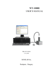
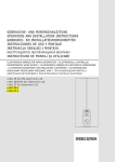
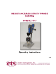
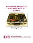
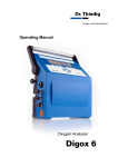
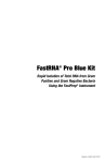
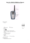
MODEL 832 CLAMP ELECTRODES
USER MANUAL
1.0 GENERAL DESCRIPTION
The Model 832 Clamp Electrode Assembly is designed
to test tubes, valves and other planar and non-planar
objects such as IC Shipping Tubes and automotive fuel
line components and assemblies in accordance with
current and proposed industry specifications requiring
resistance and/or static dissipation measurements. The
probes feature a unique dual-pad design capable of
measuring point-to-point, point-to-ground, volume
resistance/resistivity and static dissipation. The Model
832 meets the electrode configuration specified for
measuring the resistance of fuel line components and
assemblies in accordance with SAE J1645 (versions
dated 9/03 or later).
The electrodes are designed to be used with resistance meters having test voltages
of 10 and 100 volts such as the ETS Models 880 and 872 (shown below) or the
Models 871 and 863-6487. When connected to the detector plate of a charged
plate monitor such as the ETS Model 204 Charge Plated Analyzer, the electrodes
enable the user to measure dissipation time from 1kV to 100 volts, in accordance
with SAE J1645.
Model 880
Model 872
2.0 ELECTRODE DESCRIPTION
The Model 832 electrode assembly consists of one .25” square (6mm) and one
.25”x.125” (6x3mm) conductive elastomer pads with volume resistivity of 0.08 ohmcm and Shore-A hardness of 65 durometer. The pads are mounted to stainless
1
steel electrodes that in turn are mounted to an insulated clamp exerting
approximately 10 pounds (4.5kg) of force.
The smaller electrode is designed to be inserted up to 1” (25mm) into a .25” (6mm)
diameter tube such as those used in standard fuel system fittings and tubing or a
.125” x .125” (3x3mm) slot.
When measuring surface resistance the .25” (6mm) square pad is typically used.
When measuring volume resistance both pads are used. Volume resistively in Ωcm, if required, is calculated using the area of the smaller pad, (0.18 sq. cm).
Standard .162” (4mm) banana jacks are located at the end of each handle. The
BLACK jack connects to the .25” sq. (6mm) electrode and the RED jack connects
to the .25x.125” (6x3mm) electrode. Red and Black cables 30” (61cm) long,
terminated with banana plugs are supplied with each pair of Electrodes. Standard
cables with banana plugs supplied with most resistance meters are also
satisfactory for the resistance measurements. NOTE: For static dissipation
measurements, the supplied cables should be used because the higher insulation
resistance of these cables will reduce secondary leakage paths.
3.0 USING THE ELECTRODES
3.1
Material Characteristics
Loaded, thermoformed plastics consist of plastic resin filler with very high
resistance properties loaded with a small percentage of a conductive
material such as stainless steel fibers, carbon powder or fibers. When
molded, these parts exhibit either conductive or static dissipative properties
as defined in the ESD Association ADV1.0: Glossary of Terms. These
materials have bulk resistance properties verses the surface only resistance
properties found in other ESD materials. When a voltage is applied either
across or through the material the dielectric of the filler breaks down and
current flows from particle to particle. As the loading of the conductive
medium decreases, there is greater distance between particles that in turn
requires a higher voltage to break down the increased dielectric. At some
point, once a higher voltage is applied to establish continuity the resistance
of the path created may become altered permanently. Loaded thermoplastic
materials are effective in reducing the upper resistance limit to approximately
108 Ohms.
Another characteristic associated with loaded thermoplastic materials that
affects resistance measurements is the microscopic insulative layer that
develops on the surface of the molded part. The dielectric of this layer must
2
be broken down before a resistance measurement can be made. Once this
occurs the actual resistance of the part may be lower than the measuring
range of the instrumentation used.
In essence, these materials are non-linear and voltage dependent. Hence,
different test voltages will give different results. Even the series resistor
incorporated in virtually all resistance meters are different from meter to
meter which will cause variations in the measurements. Loaded
thermoelectric material is generally not adversely affected by humidity, as
long as it is reasonable such as less than 75% R.H. Currently, ESD
materials are classified as follows:
Conductive
Surface Resistance *
Volume Resistance *
<104 Ω
Dissipative
Insulative
104 to <1011 Ω
same
≥1011 Ω
* The above ranges are resistance in ohms (Ω) not resistivity in ohms/sq.
(Ω/sq.)
Materials with bulk resistance characteristics can also be classified by
specifying its volume resistivity. This is simply done by multiplying the
measured resistance by the area of the measuring electrode or material
surface, whichever is smaller, and divided by the thickness.
ρv = A/t Rm
Ω-cm
All values are in cm giving a volume resistivity in Ohms-cm. To convert to
Ohms-meter, multiply by 100.
Increasing or decreasing the thickness of the material will also change the
actual resistance of the part with a specified volume resistivity. This is a
common technique used for ESD products to achieve a particular resistance.
It is the actual resistance of the part, not its resistivity that determines how a
part dissipates a static charge.
While volume resistance or resistivity is most appropriate to classify a bulk
conductive material it is the measured resistance across or through the
affected surface to ground that is used to determine the ability of material to
dissipate a static charge.
While the resistance classifications were developed for ESD packaging
materials, most specifications referencing resistance/resistivity for materials
3
used in hazardous locations usually specify resistance limits that fall within
the Conductive range.
Finally, it should be noted that the resistance/resistivity property of material
does not predict whether the material will be low charging (antistatic) or not.
3.2
Measuring Resistance
Prior to use, the calibration of the test apparatus should be checked. Plug
the cables from the resistance meter into the BLACK banana jacks of the
Model 832. Clamp the electrodes across a 1 kohm and a 10 megohm, 1%
resistors. Measure the resistance using both 10 and 100 volts. The resistors
are not included with the clamp electrodes.
Whenever the electrostatic characteristics of materials are measured the
temperature and relative humidity at the time of measurement should be
recorded. Many materials are humidity dependent. Measurements taken at
different RH levels may result in a significant variation in the measurements.
The following recommended test procedure was developed for testing
automotive fuel system components and assemblies. The same procedure
can also be applied to just about any desired point-point, point-ground and
volume resistance measurement.
1.
Place the component or assembly being measured on a surface
having a surface resistance at least two orders of magnitude higher
than the upper resistance limit (>1x10⁹ Ohms).
2.
Verify the test set up by clamping the electrodes to a 1 kohm and a 10
Megohm, 1% resistor and measure at both 10 and 100 Volts.
3
For surface measurements, both clamps are required. Clamp both
Clamp Electrodes on to the surface with the .25” sq. (6mm) contacts
spaced apart at a desired distance on the surface to be measured. If
the area is too small then use the smaller contact. For tubing place
the .25”x.125” (6x3mm) contact inside the tube.
In all cases, make sure the contact electrode sits flat and makes
maximum surface contact with the part.
If the part has a metal ground strap take measurements at both the
point on the plastic part where the ground strap is attached and at the
point on the strap where the strap is connected to the ground point.
If using the .25” (6mm) contacts then connect the resistance meter to
the BLACK jack on each Electrode. If using the .125” (6x3mm)
contacts connect the resistance meter to the RED jacks
4.
If the resistance meter being used allows manual selection of the test
voltage, select 10 Volts.
4
Apply the voltage for 5 seconds or until a consistent reading is
obtained, then take and record the reading. If the reading is unstable,
record the reading as “unstable”.
Select 100 Volts. Apply as above and record the reading.
The lower the measured resistance, the smaller the differential
between the 10 and 100 Volt readings should be.
In most cases a product is considered acceptable if either the 10 Volt
or the 100 Volt resistance reading is within the specified limits.
Note: A measured resistance may be unstable at 10 Volts, but stable
and within the specified limit at 100 Volts. On the other hand, the
resistance may be below the measurement capability of the
instrument at 100 Volts. It is also possible the resistance is below the
measurement capability of the instrument at 10 Volts. In either case,
record that the measured resistance is less than the measurement
capability of the instrument (ex: <103 Ohms). The part would be
considered acceptable. If actual low resistance measurements are
required then use appropriate instrumentation and test voltage
to obtain the reading.
5.
3.3
To measure volume resistance, connect the resistance meter to both
the BLACK and RED jacks of a single Clamp Electrode and clamp it
to the part to be measured.. Follow the measurement procedure
above. To calculate volume resistively, multiply the measured
resistance by the area of the small contact divided by the thickness of
the material in cm (refer to Section 3.1).
Static Dissipation
This test measures the ability of a material or assembly to dissipate a charge
using the measured resistance path.
1.
Prepare the samples to be tested in the same manner as for
measuring resistance.
2.
Verify the test set up by measuring the dissipation time for a 10
megohm, 1% resistor. Connect the desired contact electrode to the
Charge Plate Monitor detector plate and the resistor as shown in
Figure 1. Connect the other electrode to ground such as the ground
connection at the wall outlet. If a battery powered CPM is used make
sure it is also connected to ground. Leave the grounding clamp
unconnected
5
Figure 1
Set the measurement parameters for a 1000 Volt charge. NOTE: The
actual charging voltage is approximately 1100-1200 Volts or more,
but the decay time measurement starts when the voltage on the part
reaches 1000 Volts and stops at the 10% (100 Volt) cut off. Apply the
charging voltage for approximately 2 seconds. Release the Charge
button and quickly connect the grounded electrode to the resistor.
Repeat the measurement 3 times. Record the dissipation times. All
readings should be ≤0.20 seconds or the minimum capability of the
CPM.
If the instrumentation includes a grounding relay module then connect
the green wire to the wall outlet and plug the cable from the grounding
electrode into the module and clamp the electrode to the other
resistor lead. Charge the system as above then depress the
“GROUND” pushbutton and record the reading. All readings should
be ≤0.20 seconds.
NOTE: Do not use the grounding function of the CPM to perform this
test. This function only grounds the detector plate.
3. Connect the electrodes to the assembly Place the assembly on a
highly insulative surface (>1012 Ohms/sq.) such as acrylic, Teflon™,
polycarbonate etc. to ensure there is no secondary leakage path for
the applied charging voltage to bleed off.
6
Figure 2
4. Apply the charging voltage for approximately 2 seconds. Immediately
ground the assembly by clamping the grounded electrode to the
desired point. Repeat the measurement 3 times and record the
results.
If the grounding module is utilized as shown in Figures 2 and 3, follow
the same procedure described for system verification.
Figure 3
7
4.0
TEST RESULTS
The above test procedures were used to measure the resistance of automotive fuel
system components and assemblies, and static dissipation of assemblies. Two
different test instruments were used for each procedure. The results are as follows:
Part
Resistance-Ohms
Dr. Thiedig Milli-TO-2
@10V
@100V
Dissipation
ETS 872
@10V
EA3
@100V
Sec
ETS 204
Sec
10 Meg Resistor
1.0 Meg
9.96 Meg
9.9 Meg
1.0 Meg
0.13*
0.5*
Fuel Filter Assy.
Hose-Hose (L)
Hose-Gnd Pt.
Hose-Gnd Strap
5.0 Meg
1.1 Meg
2.2 Gig
1.6 Meg
<1 Meg
8.1 Meg
4.7 Meg
330 Kilo
1.9 Gig
2.0 Meg
180 Kilo
25 Meg
0.13
0.13
0.13
0.5
0.5
0.5
Fuel Filter
140 Meg
Turn Electrodes 90°
22 Meg
23 Meg
24 Kilo
3.5 Meg
120 Kilo
0.13
0.5
Hose w/Conn.
>1 Gig
>1 Terra
>1 Terra
>1 Terra
10” Coated Tube
>1 Gig
>1 Terra
>1 Terra
>1 Terra
Elbow Conn.
<1 Kilo
<1 Meg
180
<10 Kilo
Test Strips
PPS-1
PPS-2
PPS-3
POM-1
POM-2
POM-3
POM-4
1.1 Kilo
<1 Kilo
<1 Kilo
1.4 Gig u/s**
23 Meg u/s
5.5 Meg u/s
680 Meg u/s
<1 Meg
<1 Meg
<1 Meg
1.1 Meg
420 Kilo
<1 Meg
7.4 Meg
2.2 Kilo
4.2 Kilo
8.0 Kilo
310 Meg
2.8 Gig
350 Kilo u/s
2.5 Gig
<10 Kilo
<10 Kilo
<10 Kilo
13 Meg
13 Meg
<10 Meg
60 Meg
Notes:
* Dissipation times are the fastest times each CPM can measure
** u/s denotes an unstable resistance measurement
Kilo
= 103
Meg
= 106
Gig
= 109
Terra
= 1012
Rev 1: 1/15/08
8
5.0 WARRANTY
Electro-Tech Systems, Inc. warrants its equipment, accessories and parts of its manufacture
to be and remain free from defects in material and workmanship for a period of one (1) year
from date of invoice and will, at the discretion of Seller, either replace or repair without
charge, F.O.B. Glenside, similar equipment or similar part to replace any equipment or part
of its manufacture which, within the above stated time, is proved to have been defective at
the time it was sold. All equipment claimed defective must be returned properly identified to
the Seller (or presented to one of its agents for inspection). This warranty only applies to
equipment operated in accordance with Seller’s operating instructions.
Seller’s warranty with respect to those parts of the equipment which are purchased from
other manufacturers shall be subject only to that manufacturer’s warranty.
The Seller’s liability hereunder is expressly limited to repairing or replacing any parts of the
equipment manufactured by the manufacturer and found to have been defective. The Seller
shall not be liable for damage resulting or claimed to result from any cause whatsoever.
The warranty becomes null and void should the equipment, or any part thereof, be abused or
modified by the customer or if used in any application other than that for which it was
intended. This warranty to replace or repair is the only warranty, either expressed or implied
or provided by law, and is in lieu of all other warranties and the Seller denies any other
promise, guarantee, or warranty with respect to the equipment or accessories and, in
particular, as to its or their suitability for the purposes of the buyer or its or their performance,
either quantitatively or qualitatively or as to the products which it may produce and the buyer
is expected to expressly waive rights to any warranty other than that stated herein.
ETS must be notified before any equipment is returned for repair.
RMA(Return Material Authorization) number for return of equipment.
ETS will issue an
Equipment should be shipped prepaid and insured in the original packaging. If the original
packaging is not available, the equipment must be packed in a sufficiently large box (or
boxes if applicable) of double wall construction with substantial packing around all sides.
The RMA number, description of the problem along with the contact name and telephone
number must be included in formal paperwork and enclosed with the instrument. Round trip
freight and related charges are the owner’s responsibility.
WARNING
PACKAGING OF DELICATE INSTRUMENTS IN WOODEN CRATES
SUBSTANTIALLY INCREASES THE CONTENT’S SUSCEPTIBILITY TO SHOCK
DAMAGE. DO NOT PLACE INSTRUMENTS OR ACCESSORIES INSIDE OTHER
INSTRUMENTS OR CHAMBERS. ELECTRO-TECH SYSTEMS, INC. WILL NOT
ASSUME RESPONSIBILITY FOR ADDITIONAL COST OF REPAIR DUE TO
DAMAGE INCURRED DURING SHIPMENT AS A RESULT OF POOR PACKAGING.
9