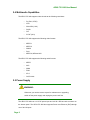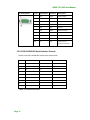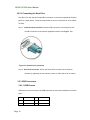
1
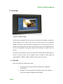
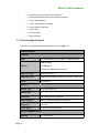
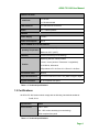
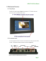
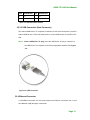
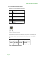
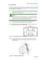
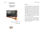
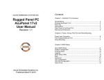
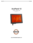
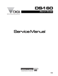
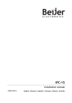
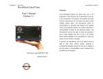
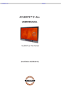
AEVU-751-X86 User Manual Acura Embedded Systems Inc. AEVU-751-X86 User Manual 1.1 Overview Figure 1-1: AEVU-751-X86 The AEVU series industrial CE touch-screen open offers both the reliability of a traditional and the flexibility of a PC. With an open, the user is able to run their own or third party software. Furthermore, the AEVU series is designed for use as a thin client device in a remote terminal environment. The AEVU series is powered by an open Windows CE 6.0 OS with rich application development support and connectivity to network and I/O devices. The AEVU-751-X86 features a low power (less than 0.5 Watts) 500 MHz RMI Alchemy™ Au1250™ media processor with an integrated media acceleration engine (MAE) that supports MPEG 1, MPEG 2, MPEG 4, WMV 9 and DivX video file formats. 1.1.1 Benefits Some of the AEVU-751-X86 benefits include: An Open design to provide both open architectures for hardware and software. Designed to fill the gap between traditional products and industrial PCs to offer traditional reliability and PC flexibility. Page 1 AEVU-751-X86 User Manual • Offers increased functionality and flexibility over traditional s at a lower cost than industrial PCs. • Enables users to configure the product for a particular application by accessing the operating system and scaling it to meet their needs. • Rugged, compact, operates over wide temperature variations, and low power consumption embedded hardware design without failure-prone hard disk and fan. • Standard peripheral connectors including Ethernet port, serial ports, USB ports, Secure Digital memory, and touch input. • Open architecture to run user or third party application software. • Thin client device application in a remote terminal environment. • The Ethernet port helps system administrators secure and separate network segments by field applications as well as communications to back-end legacy systems and central databases. • Powered by popular open Windows CE. NET embedded hard real-time operating system provides rich Windows-based functions and application software development support. • PoE (Power over Ethernet) capability reduces communications and power supply to a single CAT5e cable. • Utilities and Remote Management Tools make it easy to manage the AEVU centrally and remotely. 1.1.2 Features The AEVU-751-X86 features are listed below: • Embedded low power (less than 0.5 Watts) 500 MHz RMI Alchemy™ Au1250™ media processor • 2 MB Boot Flash • On-board 256 MB DDR2 • 1 GB Secure Digital (SD) plug and play (PnP) storage • Supports MPEG 1, MPEG 2, MPEG 4 and WMV 9 video file formats • One high performance 10/100 Mb/s Ethernet connector • One high performance 10/100 Mb/s Ethernet connector with PoE (Power over Ethernet) capability (complies with IEEE 802.3af PoE specifications) • Two USB 2.0 ports Page 2 AEVU-751-X86 User Manual • One RS-232 serial communication connection • One RS-232/422/485 serial communication connection • Two 1.5 Watt speakers • 7” color active matrix TFT display • 4-wire resistive touch panel • 12 VDC input • Cool grey frame • RoHS compliant 1.1.3 Technical Specifications The AEVU-751-X86 technical specifications are listed in Table 1-1. 196H SPECIFICATIONS SYSTEM CPU 500 MHz RMI Alchemy™ Au1250™ media processor 2MB boot flash Memory 256 MB DDR2 1 GB Secure Digital® card (internal) Real-time Clock Battery backup RTC Watchdog Timer Software programmable supports 1~255 sec. system reset Reset Reset Button DISPLAY Display Type Color active matrix TFT Display Size 7” Resolution 800 x 480, 262K color graphics Video Support MPEG1, MPEG2, MPEG4, DivX, WMV9 Brightness 500 cd/m Touch Panel 4-wired resistive touch panel 2 I/O and COMMUNICATION Ethernet Page 3 2 x 10/100 Mbps AEVU-751-X86 User Manual SPECIFICATIONS 1 x RS-232 Serial Ports 1 x RS-232/422/485 USB Interfaces 2 x USB 2.0 host connectors Audio 2 x 1.5 Watt speakers POWER Power Supply 12 VDC Power Consumption 8.5 W ENVIRONMENTAL and MECHANICAL Minimum: -20ºC (-4°F) Operating Temperature Maximum: 60°C (140°F) Humidity 5%RH to 90%RH (non-condensing) Operating Random Vibration Mode 1.Axes: 3 axes (Vertical / Transverse / Longitudinal). Vibration 2.10-500 Hz, 60min/axis. 3.Equivalent to Z:2.18 Grms X:1.6 Grms Y:1.96 Grms Front Panel Color Black C Physical Dimensions 312.5 mm x 242.6 mm x 65.1 mm (width x length x depth) Ingress Protection IP 64 compliant front panel Table 1-1: Technical Specifications 1.2 Certifications All AEVU-751-X86 series models comply with the following international standards: RoHS ,IP 64 Specification Value Environmental -20ºC – 60ºC 5% - 85% relative humidity (non-condensing) IP64 compliant front panel Table 2-1: Technical Specifications Page 4 AEVU-751-X86 User Manual 2.1 Mechanical Overview 2.1.1 Front Panel The AEVU-751-X86 front panel (Figure 2-1) comprises a 7” TFT WVGA 16-bit color 197H touch screen LCD in an ABS+PC plastic frame. Figure 2-1: Front Panel 2.1.2 Connector Panel All external peripheral interface connectors are located on the bottom panel of the AEVU751-X86 . The peripheral interface connectors are shown in Figure 2-2. 198H Figure 2-2: AEVU-751-X86 Peripheral Connectors Page 5 AEVU-751-X86 User Manual External peripheral interface connectors on the AEVU-751-X86 include: 1 x DC-IN power socket 1 x DC-IN bare wire terminal block 1 x Power switch 2 x RJ-45 LAN connectors (one supports PoE) 1 x RS-232 connector 1 x RS-232/422/485 connector 2 x USB connectors 2.1.3 Physical Dimensions The physical dimensions of the AEVU-751-X86 are shown in Figure 2-3 and listed below: 19H Page 6 Front Panel: 226mm (W) x140mm (H) x 15.68mm (D) Cabinet: 213.55mm (W) x 125.27mm (H) x 24mm (D) AEVU-751-X86 User Manual 2.2 LCD Specifications The AEVU-751-X86 has a 7” WVGA LCD screen. The LCD screen is attached to an aluminum frame that is IP 64 compliant. The specifications are shown below. Model DATA IMAGE FG0700A2DSSWBG02 Size 7” Resolution 800 x 480 (WVGA) Active Area (mm) 152.4 x 91.44 Pixel Pitch (mm) 0.0635 x 0.1905 LCD Color Native 262K colors View Angel (H/V) 2 140/100 Brightness (cd/m ) 500 Contrast Ratio 400:1 Response Time (ms) 5(Tr) / 15(Tf) Supply Voltage (V) 3.3 Backlight 1 CCFL Backlight MTBF (hrs.) 50000 Dimensions (mm) 165.0 x 104.0 x 5.5 Table 2-2: AEVU-751-X86 LCD Specifications 2.3 Touch Panel Specifications The AEVU-751-X86 has a 4-wire touch screen installed. Table 2-3 lists the touch panel specifications. 201H Touch screen EELY-ECW Type 4-wire Resolution Continuous Transmission > 80% S/W driver Windows CE 6.0 Keypad NO Table 2-3: Touch Panel Specifications Page 7 AEVU-751-X86 User Manual 2.4 Multimedia Capabilities The AEVU-751-X86 supports video decode at the following resolutions D1 (PAL, NTSC) VGA Wide VGA (16:9) QVGA GIF W GIF (16:9) The AEVU-751-X86 supports the following video formats: MPEG-1 MPEG-2 WMV9 DivX MPEG-4, MP4 and AVI The AEVU-751-X86 supports the following audio formats: MPEG AAC WMA PCM AC-3 OGG Vorbis 2.5 Power Supply WARNING: Whenever you need to remove a part for maintenance or upgrading, switch off the power supply and unplug the power cord first. The AEVU-751-X86 has a 12 V DC power input and a 6-30 V DC bare-wire connector on the bottom panel. The AEVU-751-X86 also supports Power over Ethernet (PoE) through one of its LAN ports. Page 8 AEVU-751-X86 User Manual 3.1 Installation Precautions When installing the AEVU-751-X86, please follow the precautions listed below: • Read the user manual: The user manual provides a complete description of the AEVU-751-X86, installation instructions and configuration options. • DANGER! Disconnect Power: Power to the AEVU-751-X86 must be disconnected during the installation process, or before any attempt is made to access the rear panel. Electric shock and personal injury might occur if the rear panel of the AEVU-751-X86 is opened while the power cord is still connected to an electrical outlet. • Qualified Personnel: The AEVU-751-X86 must be installed and operated only by trained and qualified personnel. Maintenance, upgrades, or repairs may only be carried out by qualified personnel who are familiar with the associated dangers. • Mounting: It is advisable at least two people assist with mounting the AEVU-751-X86. • Air Circulation: Make sure there is sufficient air circulation when installing the AEVU-751-X86. The AEVU-751-X86’s cooling vents must not be obstructed by any objects. Blocking the vents can cause overheating of the AEVU-751-X86. Leave at least 5 cm of clearance around the AEVU-751X86 to prevent overheating. • Grounding: The AEVU-751-X86 should be properly grounded. The voltage feeds must not be overloaded. Adjust the cabling and provide external overcharge protection per the electrical values indicated on the label attached to the back of the AEVU-751-X86. 3.2 External Peripheral Interface Connectors Table 3-1 lists the external interface connectors on the AEVU-751-X86. Detailed 204H descriptions of the connectors can be found following the table. Page 9 AEVU-751-X86 User Manual Connector Type 12 V DC power jack DC Jack eSATA Female connector Ethernet connectors RJ-45 Jack connector Power switch On/off switch RS-232 D-sub 9 Male connector RS-232/422/485 Serial connector D-sub 9 Male connector USB connectors Dual USB port Table 3-1: External Interface Connectors Figure 3-1: AEVU-751-X86 Peripheral Connectors 3.2.1 12V DC-In Use the rear panel +12V DC jack to connect the monitor to a power source. CN Label: CN Type: CN Pinouts: CN13 6-30V DC Jack See Table 3-3 CN Location: See Figure 3-1 208H 209H PIN DESCRIPTION 1 GND 2 GND 3 +12V Table 3-3: DC 12V Connector Pinouts 3.2.2 Serial Interfaces The system has both a RS-232 and a RS-232/422/485 serial port connector. 3.2.2.1 RS-232 Serial Interface Pinouts Pinouts for the RS-232 serial port are shown below. Page10 AEVU-751-X86 User Manual Pin Arrangement Pin No Signal Name Direction Description 1 DCD Input Carrier Detect 2 RX Input Receive Data 3 TX Output Send Data 4 DTR Output Data Terminal Ready 5 GND N/A Ground 6 DSR Input Data Set Ready 7 RTS Output Request to Send 8 CTS Input Send Possible 9 RI Input Called Status Display Shell FG N/A Frame Ground (Common with SG) Table 3-4: RS-232 Pinouts 3.2.2.2 RS-232/422/485 Serial Interface Pinouts Pinouts for the RS-232/422/485 serial port are shown below. Pin RS-232 1 RS-422 RS-485 RX- DATADATA+ 2 RX RX+ 3 TX TX- GND GND 4 5 6 7 TX+ 8 9 Table 3-5: Serial Port Pinouts Page 11 GND AEVU-751-X86 User Manual 3.2.2.3 Connecting the Serial Port The AEVU-751-X86 has two female DB-9 connectors on the external peripheral interface panel for a serial device. Follow the steps below to connect a serial device to the AEVU751-X86. Step 1: Insert the serial connector. Insert the DB-9 connector of a serial device into the DB-9 connector on the external peripheral interface. See Figure 3-5. 21H Figure 3-5: Serial Device Connector Step 2: Secure the connector. Secure the serial device connector to the external interface by tightening the two retention screws on either side of the connector. 3.2.3 USB Connectors 3.2.3.1 USB Pinouts USB devices connect directly to the USB connectors on the external peripheral connector panel. PIN DESCRIPTION PIN DESCRIPTION 1 VCC 5 VCC 2 D1- 6 D2- Page 12 AEVU-751-X86 User Manual PIN DESCRIPTION PIN DESCRIPTION 3 D1+ 7 D2+ 4 GND 8 GND Table 3-6: USB Connector Pinouts 3.2.3.2 USB Connection (Dual Connector) The external USB Series "A" receptacle connectors provide easier and quicker access to external USB devices. Follow the steps below to connect USB devices to the AEVU-751X86. Step 1: Insert a USB Series "A" plug. Insert the USB Series "A" plug of a device into the USB Series "A" receptacle on the external peripheral interface. See Figure 21H 3-6. Figure 3-6: USB Connector 3.2.4 Ethernet Connector A 10/100Mb/s connection can be made between the Ethernet connectors and a Local Area Network (LAN) through a network hub. Page 13 AEVU-751-X86 User Manual 3.2.4.1 Ethernet Connector Pinouts The Ethernet connector pinouts are shown below. PIN DESCRIPTION 1 TPT+ 2 TPT- 3 TPR+ 4 LAN_GND 5 LAN_GND 6 TPR- 7 LAN_GND 8 LAN_GND Table 3-7: Ethernet Connector Pinouts Figure 3-7: Ethernet Connector The RJ-45 Ethernet connector has two status LEDs, one green and one yellow. The green LED indicates activity on the port and the yellow LED indicates the port is linked (Table 3-8). SPEED LED Status GREEN Description ON: 100MB LINK LED Status YELLOW OFF: 10MB Table 3-8: Ethernet Connector LEDs Page 14 Description ON: Linked Flashing: Activity 213H AEVU-751-X86 User Manual 3.2.4.2 LAN Connection There are two external RJ-45 LAN connectors. The RJ-45 connectors enable connection to an external network. To connect a LAN cable with an RJ-45 connector, please follow the instructions below. Step 1: Align the connectors. Align the RJ-45 connector on the LAN cable with one of the RJ-45 connectors on the AEVU-751-X86. See Figure 3-8. 214H Figure 4-8: LAN Connection Step 2: Insert the LAN cable RJ-45 connector. Once aligned, gently insert the LAN cable RJ-45 connector into the on-board RJ-45 connector. 3.3 Mounting the System WARNING! When mounting the flat panel PC onto an arm, onto the wall or onto a panel, it is better to have more than one person to help with the installation to make sure the panel PC does not fall down and get damaged. Page 15 AEVU-751-X86 User Manual 3.3.1 Arm Mounting The AEVU-751-X86 is VESA (Video Electronics Standards Association) compliant and can be mounted on an arm with a 75 mm interface pad. To mount the AEVU-751-X86 on an arm, please follow the steps below. Step 1: The arm is a separately purchased item. Please correctly mount the arm onto the surface it uses as a base. To do this, refer to the installation documentation that came with the mounting arm. NOTE: When purchasing the arm please ensure that it is VESA compliant and that the arm has a 75 mm interface pad. If the mounting arm is not VESA compliant it cannot be used to support the AEVU-751-X86. Step 2: Once the mounting arm has been firmly attached to the surface, lift the AEVU-751-X86 onto the interface pad of the mounting arm. Step 3: Align the retention screw holes on the mounting arm interface with those on theAEVU-751-X86, as shown in Figure 4-15. 21H Figure 3-15: Arm Mounting Retention Screw Holes Step 4: Secure the AEVU-751-X86 to the interface pad by inserting four retention screws through the bottom of the mounting arm interface pad and into the AEVU-751-X86. Figure 3-16: Arm Mounting (ARM-11-RS) Page 16 AEVU-751-X86 User Manual 3.3.4 Stand Mounting The AEVU-751-X86 has Video Electronics Standards Association (VESA) standard mounting holes tapped into the rear panel. The monitor stand mounting plate has a matching VESA hole pattern. To mount the AEVU onto a stand, please follow the steps below. Step 1: Line up the threaded holes on the monitor rear panel with the screw holes on the monitor stand mounting plate. Step 2: Secure the monitor to the stand with the supplied retention screws (Figure 3-17). 2H Figure 3-17: Stand Mounting 3.4 Software The AEVU-751-X86 comes with a pre-installed Windows CE 6.0 A.1 RoHS Compliant All models in the AEVU series comply with the Restriction of Hazardous Materials (RoHS) Directive. This means that all components used to build the industrial workstations and the workstation itself are RoHS compliant. The RoHS Directive bans the placing on the EU market of new electrical and electronic equipment containing more than agreed levels of lead, cadmium, mercury, hexavalent chromium, polybrominated biphenyl (PBB) and polybrominated diphenyl ether (PBDE) flame retardants. A.2 IP 64 Compliant Front Panel The front panels on all models in the AEVU series have an ingress protection rating (IP) of 64, IP 64 or greater. The front panels are protected from dust particles and splashed water. Page 17 With the unique set of products, Acura Embedded Systems remains committed to its goal of providing trouble-free and customer-friendly service. A special customer service unit has been set up specifically to cater to our esteemed customers' needs. Technical Support: For technical support contact your Salesperson [email protected] Mailing address: Acura Embedded Systems Inc. Unit #1, 7711-128th Street, Surrey, BC V3W 4E6, CANADA Ph: (604) 502-9666 Fax: (604) 502-9668