1
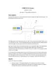
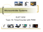
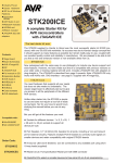
COMP2121 Experiment 4
May 14, 2007
1. Objectives
In this lab, you will gain more practical experience on microcontroller interfacing.
Specifically, your tasks in this lab are
• studying the DC motor and programming to detect and control the motor speed;
and
• studying Dot Matrix LCD and programming LCD to display output data.
2. Preparation
Before coming to the laboratory, you should:
• read through the document available at
www.cse.unsw.edu.au/~cs9032/refs/LCD_Manual.pdf for general
•
•
•
•
description of Dot Matrix LCD
read through Atmega64 data sheet on how to use Timer 0 to generate Phase
Correct PWM signals.
read through the task description of this experiment, trying to understand what
you will be doing;
write your programs at home in order to finish the experiment on time; and
obtain one or two floppy disk on which to store your work.
3. Introduction to the DMC LCD and the DC Motor
3.1
DMC LCD
The AVR Microntroller Board comes with a 2 × 16 character Liquid Crystal Display (LCD)
module. This module can be controlled via any of the ATmega64 ports.
In order to read/write from/to the LCD, here is the list of things you must satisfy:
• Initializing LCD
• Checking the busy flag of LCD
• Determining which register (instruction register or data register) in the LCD
controller to write to or read from
• Read/write data from/to the LCD
The pin descriptions, timing constraints and detail instruction specifications can be found
in the LCD User’s Manual.
3.2
DC Motor
The motor on the AVR Microcontroller Board is DC voltage driven. It takes the input
electrical energy and converts the energy into rotating motion.
1
The speed of the motor is measured in revolutions (or rounds) per second (rps).
To determine the motor speed, we can use the shaft encoder. The encoder uses infra
red emitters and detectors that are placed fairly close to each other (about
half an inch or less). When there is a direct line of sight between them the detector is
“on”’ and produces a voltage (normally around 1 to 3 volts). When the line of sight is
blocked the detector doesn’t pick up any infra red light so is “off”, producing 0 volts.
Now, carefully examine the motor and shaft encoder on the AVR Microcontroller Board.
Can you identify the emitter and the detector? The emitter is active high and the detector
is active low (It will go low when it can see the signal).
Power up the AVR Microcontroller Board as from last lab, wire up the POT to the MOT
using the patch cables provided. As you turn the POT, the motor spins at different
speeds.
As you have already noticed, there are 4 holes on the motor, the combination of the
motor and shaft encoder enables you to measure the frequency of the motor by counting
the number of the holes the shaft encoder detects and dividing the number by 4.
4. Tasks
4.1
Task 1
Write an assembly program that receives a character typed in from the keypad and
prints it on the LCD. When the first line is full, the display goes to the next line. When the
two lines are all full, the display is cleared and ready to display a new set of characters.
Assemble your program using AVR Studio, and run it on the AVR Microcontroller Board.
Demonstrate your working program to the Laboratory assessor.
Check Point A:
Signature:
2
4.2
Task 2
Write an AVR assembly language program that measures the speed of the motor by
counting the number of holes that has been detected using the shaft encoder, and
displays the motor speed of on the LCD.
Note: There are two ways to measure speed: counting holes in a given period of time or
measuring time for a complete revolution of the wheel (or several revolutions to average
things out). Whichever method you choose is up to you.
The Detector can be read by an interrupt. The detector usually will output a 1 when there
Is not a hole, so you can use the falling edge of the detector to trigger an interrupt to
count a hole.
1. Method 1: Timing can be done with Timer 0 or any of the other timers in the chip.
Count Overflow interrupts to measure a period of one second while counting the
number of holes that pass by using an external interrupt. Every second you can
update your speed on the LCD.
2. Method 2: Set up the timer to time over an appropriate period. Wait for the first
external interrupt to indicate the first hole and record the timer value. After four
more external interrupts you know that 1 revolution has occurred. Find the
difference between the start and end times (you may also need to count the
number of timer overflows) and you can calculate the period of rotation for the
wheel. From this value you can work out how many revolutions could occur in a
second and display it.
The first method is fairly simple but will only update every second. The second method is
a little more tricky, but gives you much higher accuracy and a MUCH faster refresh rate
(in fact you will probably have to limit this rate if you want to read the number off the LCD
in time).
Assemble your program using AVR Studio, and run it on the AVR Microcontroller Board.
Demonstrate your working program to the Laboratory assessor.
Check Point B:
Signature:
3
Appendix: Pulse Width Modulation
PWM is a way of digitally encoding analog signal levels. Through the use of highresolution counters, the duty cycle of a square wave is modulated to encode a specific
analog signal level. The PWM signal is still digital because, at any given instant of time,
the full DC supply is either fully on or fully off. The voltage or current source is supplied
to the analog load by means of a repeating series of on and off pulses. The on-time is
the time during which the DC power is supplied and the off-time is the period during
which that the power is not supplied. Given a sufficient bandwidth, any analog value can
be encoded with PWM.
Figure 1 shows three different PWM signals. Figure 1a shows a PWM output at a 10%
duty cycle. That is, the signal is on for 10% of the period and off the other 90%. Figures
1b and 1c show PWM outputs at 50% and 90% duty cycles, respectively. These three
PWM outputs encode three different analog signal values, at 10%, 50%, and 90% of the
full strength. If, for example, the supply is 5V and the duty cycle is 10%, a 0.5V analog
signal results.
Figure 1 PWM signals
PWM is a common technique for speed control. A good analogy is bicycle riding. You
peddle (exert energy) and then coast (relax) using your momentum to carry you forward.
As you slow down (due to wind resistance, friction, road shape) you peddle to speed up
and then coast again. The duty cycle is the ratio of peddling time to the total time
(peddle+coast time). A 100% duty cycle means you are peddling all the time, and 50%
only half the time.
PWM for motor speed control works in a very similar way. Instead of peddling, your
motor is given a fixed voltage value (say +5 V) and starts spinning. The voltage is then
removed and the motor “coasts”. By continuing this voltage on-off duty cycle, motor
speed is controlled.
5
To control the speed of a DC motor, we need a variable voltage DC power source.
However, if you take a 5V motor and switch on the power, the motor will start to speed
up, motors do not respond immediately so it will take a small time to reach full speed. If
we switch the power off, sometimes before the motor reaches full speed, then the motor
will start to slow down. If we switch the power on the off quickly enough, the motor will
run at some speed part way between zero and full speed. This is exactly what a PWM
controller does; it switches the motor on in series of pulses. To control the motor
speed it varies the width of the pulses – hence Pulse Width Modulation.
PWM can be controlled on the Atmega64 through the use of Timer 0 and its Phase
Correct PWM mode. This is explained in the datasheet in the Timer 0 chapter (pp99100). You should read this section before continuing.
Basically, you control the timer to vary the duty cycle of the signal on the output pin that
varies the average voltage on the pin that controls the motor speed. PWM allows 256
different duty cycles to be output to the device. Not all of these are high enough to
overcome the friction of the motor shaft, but most will allow you to control the motor
speed with fairly good accuracy.
Timer 0 allows control of the PWM on pin B4 of the microcontroller. Therefore you
should be connecting PORT B4 to the motor to control it this way. Once the timer is set
up to perform PWM, you can control the duty cycle and therefore control the speed of
the motor by using the OCR0 port. This can be set up so that increasing the value of this
port will increase the duty cycle of the output pin.
The ports used to control the PWM are described below. All references to tables and
figures are those in the Atmega64 datasheet.
Timer Counter Control Register (TCCR0):
This port controls the timer. The bit values you need to control are described.
•
•
•
•
Bit 7 - FOC0: This bit is not used for PWM it should be 0.
Bits 6,3 - WGM01:0: These bits determine what mode the timer is in. Table 52
shows that WGM00(bit 6) should be 1 and WGM01(bit 3) should be 0 to enable
PWM mode.
Bit 5:4 - COM01:0: These bits further control the output type of the PWM signal.
Table 54 shows the values for this pin. To enable the type of PWM we want, set
COM01 to 1 and COM00 to 0.
Bit 2:0 - CS02:0: These pins select the clock speed used. It doesn’t really matter
what speed you set the clock to for PWM, so you can just use the value ”001” for
these three bits
Timer/Counter Register (TCNT0):
This port contains the current value of the timer. You can read this value if you want to
find the current time but it’s not required.
Output Compare Register (OCR0):
6
The value on this port determines the duty cycle. The larger the value, the higher the
duty cycle and the faster the motor will go.
Timer/Counter Interrupt Mask Register (TIMSK):
This allows you to create an interrupt if you wish, but you probably won’t need these.
The interrupt types are: Timer Overflow (TOIE0): Interrupts every time the timer
overflows (i.e. at the frequency of the clock. Output Compare(OCIE0): This interrupt
occurs whenever the output is going to change. You can get a better understanding of
these interrupts from Figure 40.
7