1
Unicorn Limited
Counter/Classifier
Field Unit Instruction Manual
DIAMOND TRAFFIC PRODUCTS
PO BOX 1455
76433 ALDER STREET
OAKRIDGE, OR 97463
VERSION: 1.5
ISSUE DATE: 04/15/2011
FCC Compliance
Note: This equipment has been tested and found to comply with the limits for Class B digital devices, pursuant to part
15 of the FCC Rules. These limits are designed to provide reasonable protection against harmful interference in a
residential installation. This equipment generates uses and can radiate radio frequency energy and, if not installed and
used in accordance with the instructions, may cause harmful interference to radio communications. However, there is
no guarantee that interference will not occur in a particular installation. If this equipment does cause harmful
interference to radio or television reception, which can be determined by turning the equipment off and on, the user is
encouraged to try to correct the interference by one or more of the following measures:
Reorient or relocate the receiving antenna
Increase the separation between the equipment and receiver
Connect the equipment into an outlet on a circuit different from that to which the receiver is connected
Consult the dealer or an experienced radio/TV technician for help
The user is cautioned that changes or modifications not expressly approved by Diamond Traffic Products could void the
user’s authority to operate the equipment.
Page 2
Unicorn Limited User Manual
INDEX
1. Introduction ....................................................................... 4
1.1 How to use the Manual ...................................................... 5
1.2 Communication with the Unicorn Limited ........................ 5
1.3 System Components .......................................................... 6
1.4 Features not available from the keypad ............................. 6
2. Modes, Sensors, and How to use them ............................. 7
2.1 The Three Basic Storage Modes........................................ 7
2.2 Raw Per Vehicle Storage and Specific Functions ............. 7
2.3 Binned Storage and Specific Functions ............................. 9
2.4 Count Storage and Specific Functions ............................... 9
3. Hardware ......................................................................... 10
3.1 Keypad ............................................................................ 10
3.2 LCD Display ................................................................... 11
3.3 Serial Port ........................................................................ 11
3.4 Road Tubes ...................................................................... 12
4. Keypad Operation ........................................................... 13
4.1 How to use the Menus ..................................................... 13
4.2 The Two Main Menus ..................................................... 13
4.2.1 Not Collecting Data menu ............................................ 13
4.2.2 Collecting Data Menu................................................... 14
4.3 Start Collecting ................................................................ 14
4.3.1 Questions asked with Any Storage Mode ..................... 15
4.3.2 Lane Grouping Questions ............................................. 15
4.3.3 Questions asked with Raw Per Vehicle Storage ........... 16
4.3.4 Questions asked with Binned Storage Mode ................ 17
4.3.5 Questions asked with Count (Volume) Storage Mode . 18
4.3.6 Questions asked with Sensor Storage Mode ................. 19
4.3.7 Final Start Questions .................................................... 19
4.4 Show Status ..................................................................... 20
4.5 Delete Files ...................................................................... 21
4.6 View Lane Totals ............................................................ 22
4.7 Configure System ............................................................ 22
4.8 Cold Restart ..................................................................... 23
4.9 Stop Collecting ................................................................ 24
4.10 Monitor Lanes ............................................................... 24
4.11 Monitoring Raw or Binned Data Collection .................. 25
4.12 Monitoring Count Data Collection ................................ 25
Unicorn Limited User Manual
5. Keypad Operation Examples ......................................... 26
5.1 Configuring the System ................................................... 26
5.2 Collecting Raw Data ....................................................... 28
5.3 Collecting Binned Data ................................................... 30
5.4 Collecting Count Data ..................................................... 33
5.5 Monitoring Traffic & Viewing Status ............................. 35
5.6 Stop Collection ................................................................ 36
5.7 File Deletion .................................................................... 36
5.8 Collecting Data Using Lane Grouping ............................ 37
6. In-Day Times ................................................................... 38
7. Site Naming Conventions ................................................ 39
Appendix A. Trouble Shooting .......................................... 40
Appendix B. Memory Usage ............................................... 41
Appendix B.1 Raw Data Collection ...................................... 41
Appendix B.2 Binned Data Collection .................................. 42
Appendix B.3 Count Data Collection.................................... 44
Appendix B.4 Sensor Data Collection .................................. 44
Appendix C. Plugs and Connectors ................................... 45
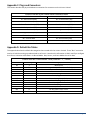
Appendix D. Default Bin Tables ........................................ 45
Appendix E. Road Tube Problems & Solutions ............... 47
Appendix E.1 Missed Axles .................................................. 47
Appendix E.2 Extra Axles ..................................................... 49
Appendix E.3 Bad Speed and/or Length ............................... 49
Appendix E.4 SnMis (Sensor Miss) for Entire Vehicle ........ 49
Appendix E.5 One Vehicle Shown as Two ........................... 50
Appendix E.6 Road Tube Setup ............................................ 50
Page 3
1. Introduction
Thank you for purchasing the Unicorn Limited Field Unit. You have purchased one of the finest traffic classification
counters available today. This manual describes the operation and programming of the Unicorn Limited Field Unit.
Please read this manual before attempting data collection.
What is a “Unicorn Limited Field Unit”?
The Unicorn Limited is a traffic data-gathering instrument for use in the field. Speed, Length, and Number of Axles are
a few types of data that can be gathered with this instrument.
The cast aluminum case is durable, light weight, and weather resistant. The interior keypad & display are both sealed
to prevent moisture from damaging them. In addition, a rubber seal is installed around the lid to further protect the
unit from the weather.
The case also contains a lid securing mechanism and aluminum carrying handle. The outside rear of the case contains
two or four Air Switches. The battery charger and serial interface plug are on the face plate of the counter.
The electronic circuit board inside the case contains the microprocessor, backup battery, charging circuitry, memory,
and all other support circuitry for the unit.
Some tips to prolong the life of your Unicorn Limited
When collecting data avoid placing unit in drainage ditches or areas prone to flooding.
Always dry the unit out completely after removing from the field.
Always push the dust caps onto unused Air Switch nozzles.
Keeping the battery fully charged will prolong its service life. Recharge the battery every six weeks when not in
use.
Disconnect the serial interface plug if serial communication is not required. This will substantially reduce
power consumption and prolong battery life.
Do not attempt service without qualified personnel. The components of the Unicorn Limited are very static sensitive,
and improper handling can damage the components.
Page 4
Unicorn Limited User Manual
1.1 How to use the Manual
This manual completely describes the use of the Unicorn Limited. The only thing not covered in this manual is
programming and retrieving data from the serial port with a PC. This is covered in the Centurion Windows Software
Manual.
Do I have to read the whole manual?
Anybody using a Unicorn Limited should read all of Section 1, 2, and 3 of this manual. This will familiarize you with the
basic equipment provided and what types of data you can collect. From that point there are three methods of
operation:
Method 1 -
To operate the Unicorn Limited entirely from it’s built in keypad. All setup and configuration can be
done from here. Data may be retrieved by a Data Hog or a computer running Centurion Software. If
this is the method you want to use, first read sections 4.1 and 4.2, then read section 5 for an example
which matches your application.
Method 2 -
To operate the Unicorn Limited only from a computer using Centurion software. All setup and
configuration can be done from a computer, in addition to retrieving the collected data. If this is the
method you want to use, simply refer to the Centurion Users Manual for more information. Use this
field unit manual for clarification and technical information on the Unicorn Limited.
Method 3 -
To operate the Unicorn Limited using both a computer and its built in keypad. This is the most
common method since you might not always have a computer with you, and becoming familiar with
the keypad operation is always useful. We suggest that you first attempt to run the counter using the
built in keypad (first read section 4.1 and 4.2 then follow the examples in section 5). After collecting
some data with the Unicorn Limited, move on to using the software to setup for data collection. From
that point, read through the rest of the software manual for more information on controlling the
counter through a computer.
1.2 Communication with the Unicorn Limited
Communicating with the Unicorn Limited is done through the built in Keypad/Display, or through the serial port to a PC
or laptop. Our Centurion software package allows such advanced features as:
“Pop-up windows and “User-Friendly” menus.
Complete Database functions with viewing and editing of all collected data.
XModem transfers for data file retrieval, with later file format conversion utilities & detailed printouts with
analysis (Hourly and daily summaries).
Complete monitoring and configuration.
To learn more about using this program, refer to the Centurion Users Manual. Note that Unicorn Limited’s serial
access is not restricted to use with any particular type of computer. Any computer that supports a standard serial
communications (RS232) will suffice. With the advent of USB to Serial controllers, even those newer computers are
able to communicate with Legacy hardware.
Unicorn Limited User Manual
Page 5
1.3 System Components
You must have the following equipment in order to use the Unicorn Limited. All of this equipment can be purchased
from Diamond Traffic Products.
Unicorn Limited Field Unit Instruction Manual.
Centurion City/County Software.
A Battery Charger or counter fitted with a solar panel on the lid.
A Serial Interface Cable between the counter and a computer.
Road tube sensors and assorted hardware for securing to the road. (i.e. nails, road tube grips, hammer and
tape measure).
Computer. Ideally, this would be a PC with the Centurion Software installed.
1.4 Features not available from the keypad
The Unicorn Limited has several features which are not available directly from the counter keypad. Some features
require too much internal firmware to use from the keypad and therefore are only accessible through the serial port.
Also, some of these features only relate to serial port use, and therefore are not available via the keypad.
The following features are available from the serial port using Centurion software.
Page 6
Data Retrieval – The most important counter function is the retrieval of collected data.
Daylight Saving Time Adjust – You can manually or automatically have software set the Unicorn Limited to
handle Daylight Savings Time changes. The Unicorn Limited will change the time and adjust data appropriately
if you choose automatic.
SnMis #3 to Vehicle – This specialized function, not commonly used, is accessible from a special hidden menu
which is called up using the ALT+F10 key from the main counter link screen. The counter must not be
collecting data to set this function.
In-Day Times – In-Day times are specific time periods inside of a 24-hour period in which you want to collect
data, and all other times will be excluded. What this basically does is make the counter create a new data file
several times during the day. For example, if you selected two In-Day Times of 0600-1200 and 1600-1800,
then the counter would create two files per day, each containing data for the appropriate time period. See
section 6 for more information on In-Day Times.
Counter Serial Number – The counter contains a built in firmware serial number. This serial number, set at the
factory, is included with all data files so that the specific counter that collected the data can be easily
identified. You can optionally set your own serial number using the ALT+F10 function from the main counter
link screen in the software.
GPS Coordinates – The Unicorn Limited is equipped to read GPS coordinates from any NMEA compatible
receiver with a serial output. Connecting to the GPS receiver will allow the unit to download the coordinates
straight into the Unicorn Limiteds information line for later site identification.
Unicorn Limited User Manual
2. Modes, Sensors, and How to use them
This section of the manual discusses three methods the Unicorn Limited can be used to collect data.
2.1 The Three Basic Storage Modes
You should first become familiar with the three fundamental modes of operation. The mode that you select
determines the type of data that will be collected and whether the information will be combined with other entries or
stored individually.
Raw (per vehicle)
This mode will store each vehicle in memory as it passes by. The following information about
each vehicle can be stored in memory: time, speed, number of axles, spacing between each
axle, overall length, and bin classifications.
Binned
This mode is the conventional classifier storage mode. Each vehicle is given four (4) different
bin numbers. Each bin number represents a category the vehicle belongs to. The four (4) bins
are Axle Class, Speed Class, Gap Class, and Headway Class. The parameters for each bin can
be changed by the user. The most commonly used values are built into the Unicorn Limited, as
defaults. When bin-classifying, users specify a time interval, such as every 15 minutes. The
total number of vehicles for each bin will be stored in memory.
Count
The count mode is the simplest mode of operation; it is used when just a vehicle count is
desired. The Unicorn Limited provides the total number of axles detected, optionally divided
by two. Users specify a time interval, such as 15 minutes or every hour, in which these total
counts will be stored in memory.
The Unicorn Limited supports two (2) or four (4) Road Tube Air Switches. Road Tube Sensors are considered “Axle”
sensors; since individual vehicle axles are used activate them.
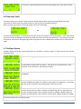
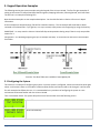
2.2 Raw Per Vehicle Storage and Specific Functions
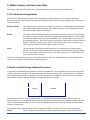
In this mode, an individual record is kept for each vehicle encountered. Any combination of one to two lanes can be
enabled. If any lane is configured for directional mode (the ability to classify traffic in either direction), an additional
lane of traffic data is created. For example, if lane #1 is enabled and is configured in directional mode, the counter
would create lane #3 for vehicles traveling in the opposite direction on lane #1.
Physical Lane
Opposite Direction Lane
Lane #1
Lane #3
Lane #2
Lane #4
The directional lane is not an actual separate lane – it is the same physical lane but simply traffic moving in the
opposite direction. It is recommended that the directional option be used whenever the possibility of two-way traffic
exists, such as a one-lane road or an area on a two-lane highway where there is passing of slower vehicles, thereby
using the oncoming lane.
Four separate data formats of Raw Per Vehicle storage are available. All lanes will be in the same data formats.
Normal
This is a straight raw vehicle format, which will store lane number, time, speed, number of
Unicorn Limited User Manual
Page 7
axles, and spacing between each axle.
Enhanced
This data is in the same format as Normal, with the exception that speed is now calculated to
tenths of a MPH or KPH and the overall vehicle axle length is added to the record.
Raw with Bins
The data is the same as normal except the Speed, Axle, Length, Gap, and Headway bin
numbers are stored with each record. This format does not store the data in binned format,
but will tell you which bin a vehicle would have gone into if you were binning.
Enhanced with Bins
This format is a combination (as the name implies) of Enhanced and Raw with Bins. The data
is now Enhanced and stored with the bin numbers.
There is some give and take with the data formats. Enhanced Raw will give a more precise record than Normal Raw;
however, more memory space is used. The same goes for Raw with Bins – more memory to keep track of which bin it
would have gone in. Appendix B gives an approximation of the number of vehicles that can be stored in memory
depending upon which data format you choose.
While in Raw Per Vehicle storage, the system will ask the user for Sensor Spacing. The maximum sensor spacing is 99.9
feet. We suggest 4 feet between sensor 1 & 2 and also between 3 & 4.
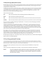
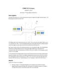
The Unicorn Limited Raw Storage mode supports “Lane Overlap”. If axle sensors are used to collect data from two
lanes of traffic, the lanes can be configured as shown in the figure below. Note that the shorter tube is in the near lane
(lane #1), and is activated first by oncoming traffic. This configuration will allow you to collect data from two lanes
using 4 road tubes where one set of tubes crosses both lanes. Note: that lane overlap can support lanes which vehicles
are going the same or opposite direction.
Important Note: You must make sure that for each road tube pair that the longer tube is always equal to or longer than
the shorter tube in the pair when measured from the edge of the pavement closest to the counter. For example, when
doing Same Direction road tube 3 (of pair 1 & 3) must be equal to or longer from the edge of the pavement to the
counter than road tube 1 is from the edge of the pavement to the counter. The same is true for pairs 2 & 4. In the
Opposite Direction, the pairs change to 1 & 4 and 2 & 3 where road tube 4 must be longer from the edge than road
tube 1 and road tube 3 must be longer than road tube 2.
Raw data is stored in a straight forward fashion. As vehicles are detected and the information (speed, length, etc.) is
gathered, the data is stored sequentially in memory in one long record. During collection, or during testing, the
Unicorn Limited will allow you to monitor any or all lanes.
Page 8
Unicorn Limited User Manual
2.3 Binned Storage and Specific Functions.
Binned storage is very similar to Raw Per Vehicle Storage in that you can have any combination of lanes and each lane
can be enabled for directional operation giving additional lanes of directional traffic. Binned storage uses the same
road tube layouts as Raw per Vehicle.
The difference in the modes is the method of storage. In Raw per Vehicle storage, the Unicorn Limited stores all data
in chronological order as the vehicles are detected and data is registered (speed, length, etc.). Binned Storage sorts
and classifies the data into separate categories or “bins”. The vehicle is then added to the correct Bin #. In this
fashion, you can retrieve totals for various types of vehicles.
There are four basic bin types:
Axle
Data is binned by Number of Axles and Spacing Classification FHWA (Scheme-F).
Speed
Data is binned by the individual vehicles speed.
Gap
Data is binned by the distance between vehicles, from the tail of the first to the nose of the second.
Headway
Data is binned by the distance between vehicles, from the nose of the first to the nose of the second.
Each lane can also be enabled to do binning of “Speed by Axle”. This mode can create a table giving you individual
speed bins for each vehicle type.
The bins are compiled over a user specified time length, or “record interval”. Up to five separate start times and
sampling lengths are available (within a 24 hour period) for use. This allows specific sample periods to be adjusted
according to the time of day. An example would be to select one hour intervals from 00:00 until 05:00, 15 minute
intervals from 05:00 to 10:00, one hour intervals from 10:00 to 15:00 (3pm), 15 minute intervals from 15:00 to 19:00
(3pm to 7pm), and 1 hour intervals for the remainder of the day ending at 23:59.
Each category or “Bin” has been pre-defined as to what it represents. For example, Axle Bin #1 is for motorcycles,
Speed Bin #1 is for vehicles traveling between 1 and 19.9 MPH. While these bins have been preset to be the most
common categories, you may change the type and number of bins for each binning mode. See the Centurion Users
Manual for more information on modifying these bin definitions to your own specific needs.
Binned Storage also supports the “Lane Overlap” function. Refer to the previous section, “Raw Per Vehicle Storage and
Specific Function” for detailed explanation.
2.4 Count Storage and Specific Functions
In Count Storage mode, the only information stored is the number of vehicles that have been detected in each lane.
Up to two lanes are supported in this mode. Normally, each lane will use only one sensor to collect the count. When a
Road Tube Sensor is used as a lane sensor, the count may be divided by two.
Storage of the counts is performed in the same manner as outlined above for Binned data (i.e. using “record
intervals”).
There are three sensor configurations for Count Data. They are Lane Normal, Subtraction and Directional.
Normal
This sensor configuration would be used when the counter can be located in a center median of a
roadway and road tube is counting traffic, on one side of the median while another road tube is
counting traffic on the other side. The data from each road tube is stored and in no way affects
data from the other road tube.
Unicorn Limited User Manual
Page 9
Lane Subtraction
This road tube configuration is used when you want to get individual lane count from two different
lanes of traffic from one side of the road. The road tube attached to Lane 1 (or any other ODD
numbered lane) is laid out across both lanes. The road tube attached to Lane 2 (or any other EVEN
numbered lane) is laid out across one lane. The Unicorn Limited will subtract the even lanes from
the odd lane’s count to obtain the proper directional count for the odd numbered lane.
Directional
This road tube configuration is used for counting two-way traffic on a narrow road. A road tube
pair (such as 1-2 or 3-4) is laid out across both lanes of a road one foot apart. The Unicorn Limited
will determine (from the order of actuation) the proper directional count for each lane.
You can monitor any or all lanes during collection or testing, with the system showing you the current activations as
they occur.
3. Hardware
This section describes the hardware components associated with the Unicorn Limited system.
3.1 Keypad
The Unicorn Limited contains a built in 16-key keypad. With this keypad and the four (4) line, twenty (20) character
per line LCD display (Section 3.2) you can completely program and operate the Unicorn Limited. When the ALT key is
held down while you are pressing another key, an alternate set of keys is available to the user. The table below shows
the alternate keys.
ALT
0
1
2
3
4
5
6
7
8
9
CLEAR
ABC
DEF
GHI
JKL
MNO
PQR
STU
VWX
YZ[
-./
ABORT
A…
Table 1 – Alternate Keypad Entry
Note that if the ALT key is continuously held and the number is pressed, again, the letter will scroll through the
following possibilities of letters:
ABCDEFGHIJKLMNOPQRSTUVWXYZ[]^abcdefghijklmnopqrstuvwxyz{|}!”#$%&’()*+-./0123456789:;?@
Page 10
Unicorn Limited User Manual
For example, if you wanted the letter “W” you would press and hold the “ALT” key and press the “7” key. Note that
“V” appears in the space, as shown in Table 1. While still holding the “ALT” key, press the “7” key again, and the letter
“W” will appear. Release the “ALT key and the letter remains. You can also press the right and left arrow keys (while
the ALT key is down) to scroll through the alphabet.
The rest of the keys are explained below:
Enter
Used as a means of indicating to the Unicorn Limited that an option is complete and ready to be acted
upon.
Clear
Used as a means of backing up one configuration option or menu item.
Space
The <Space> key inserts a space at the cursor location and will also allow scrolling through options in
ascending order.
Left Arrow
This key allows viewing/selecting of options in descending order. Also used as a non-destructive
backspace key when entering a line of data.
Right Arrow
one
This key allows viewing/selecting of options in ascending order. It is used to move non-destructively
position to the right when entering a line of data.
ALT
Used only in conjunction with other keys; ALT allows existing keys to perform alternate functions. Use
of the ALT key is similar to the SHIFT key on a keyboard, in that the ALT key must be pressed and
held for the duration of the associated key press.
3.2 LCD Display
The Unicorn Limited is equipped with a four-line Liquid Crystal Display (LCD). Each line displays up to 20 letters or
numbers. This display is used in conjunction with the keypad to program and operate the Unicorn Limited. You will
see various questions and information displayed at different times. Please refer to the appropriate section of this
manual for more information on specific questions and displays.
The LCD used in the Unicorn Limited consumes very little power, thereby minimizing battery drain during setup and
monitoring procedures. To further save battery power, the Unicorn Limited will turn off power to the display when
data collection is active and the display is not being used.
Road dust will inevitably cover the display from time to time, and the display will need to be cleaned off. When
cleaning the display, it is best to attempt blowing off as much dust as possible before wiping the surface with a soft
damp clean cloth. This method limits the chances of scratches being caused by the abrasive particles found in road
dust.
3.3 Serial Port
The serial port is used for the retrieval of traffic data that has been collected by the Unicorn Limited. All serial devices
are connected to the Unicorn Limited through the DB-9 Serial Port plug (located on the lower right side of the face
plate). Note that the Unicorn Limited can be completely programmed and operated from the serial port via Centurion
CC Software. Although lower versions of Centurion can communicate and program the Unicorn Limited, the use of
Centurion CC is required to process classification data.
The serial port supports Baud Rates from 300 baud to 115200 baud. The retrieval of data must be done through the
serial port. The method of transfer is XModem-1k with CRC error checking. An automatic switch to 128 Byte XModem
transfer occurs when the system gets 10 or more errors, indicating a noisy line. Data will transfer faster with larger
blocks.
Unicorn Limited User Manual
Page 11
You will need to connect the Unicorn Limited to a computer to retrieve your data. Note that any computer
with a standard RS232 serial port plug (DB-9) may be connected. Also most USB to Serial Devices have proven
to work as well.
3.4 Road Tubes
Road Tubes, or “Tubes”, refer to hollow rubber tubes usually ranging from 30 to 100 feet in length. These Tubes are
stretched across the roadway so that oncoming vehicle traffic drives over them. This generates a sound-wave (or an
“air pulse”), which travels down the tube and allows the electronics of the Unicorn Limited to determine that a vehicle
axle has passed. We recommend a spacing of 4 feet between Road Tubes used for data collection in the same lane.
Note: there will be some loss of count if road tubes longer than 60’ (20 meters) are used.
Tubes offer the advantage of being easily movable, quick to install, inexpensive, and capable of detecting individual
axles of a vehicle. Their disadvantages include rapid wear, hard to secure for long periods, and drivers notice the tubes
and possibly change speed, lanes, etc.
Follow these guidelines when using tubes with the Unicorn Limited:
The counter will work with road tubes between 30’ and 100’ long. (Note: tubes shorter than 30’ are NOT
recommended as they will damage the air switch over time).
If collecting Raw or Binned data, make sure each lane’s tubes (two per lane) are the SAME LENGTH. Also, try to
stretch the tubes the same amount when securing them to the roadway i.e. 10%.
Make sure the tubes are placed as squarely as possible to the oncoming traffic (so that both wheels of a
vehicle strike the tube simultaneously).
After each use, check the tubes for punctures or other damage.
Plug the far end of the tube with a suitable device to keep dirt and other debris out.
How to connect the tubes to a Unicorn Limited when collecting Raw Per Vehicle or Binned Data:
Get two equal lengths of road tube for each lane desired.
Install one road tube perpendicular to the direction of traffic across a single lane of traffic. You can string road
tubes across multiple lanes using the “Lane Overlap” function or the “Directional” mode. This is fully covered
under Section 2.2.
Install the second road tube perpendicular to the first tube. (We do NOT recommend spacing closer than 4
feet when classifying due to potential loss of speed accuracy). Connect the road tube, which will be hit first by
oncoming traffic into the 1st Input Nozzle for the particular lane you are using.
Connect another road tube, which will be hit second by oncoming traffic into the 2nd Input Nozzle for the
particular lane you are using.
How to connect tubes to a Unicorn Limited when collecting Count Data:
Install a road tube perpendicular to oncoming traffic across a single or dual lane of traffic.
Connect the road tube to the nozzle on the Unicorn Limited for the lane you are using.
If you are using at least two lanes and you want to use Lane Subtraction or Directional function, you may want
to read about these functions in Section 2.4 for more information on how to correctly install and connect
tubes.
For important information regarding tubes and potential errors, see Appendix E.
Page 12
Unicorn Limited User Manual
4. Keypad Operation
This section describes the full operation of the Unicorn Limited Field Unit using the built in keypad. For information on
operations using the Serial Port, please refer to the Centurion Users Manual.
Note: That virtually all features of the Unicorn Limited can be controlled with the keypad. The only exception is the
Data Retrieval, in which case you must use the Serial Port and a computer, or a data retriever such as Diamond Traffic
Products Data Hog.
4.1 How to use the Menus
The Unicorn Limited menu structure has been designed to take full advantage of the system’s capabilities with minimal
effort and confusion on the part of operator. The menu system has been designed so that only those options that may
be needed at any particular point are available. Selection of an option from within a menu is a simple matter of using
the arrow keys. Press the direction you wish to go (either right arrow for forward through the menus or left arrow for
backwards through the menus) and the press the ENTER key to activate that option. The menus will automatically rollover at the end, so by pressing one direction or the other the desired option will always appear.
An alternate method of selection is to type the number, which corresponds to the desired option. Each option has a
number to which it may be referenced directly. These numbers are located on the inside of the Unicorn Limited lid.
This method has the benefit of skipping all other options by proceeding immediately to the one specified. Press ENTER
to activate the option once it has been selected.
Pressing the CLEAR key will abort an option. This backs the Unicorn Limited up one question per key press until you
return to the main menu. If you press CLEAR at the menu when data collection has started, the Unicorn Limited will be
placed in to a special sleep mode and the LCD will go blank. At this point the Unicorn Limited will turn off the display
to save power. Note that the counter continues to collect data in this mode. Do NOT turn off the Units Power.
You can turn the display on the counter back on at anytime by pressing the ENTER key.
Serial Cable Connection:
If a serial cable is connected, the counter will instantly switch from the menu to a screen which shows “Serial Active”.
If you want to use the regular keypad menu after a serial cable is connected, simply press ENTER and you will be
returned to the menu and ALL SERIAL PORT INPUT IS IGNORED! Press the CLEAR key from the menu when you are
finished and the counter will return to the “Serial Active” state it is again ready for communication with a computer or
data retrieval device.
4.2 The Two Main Menus
The Unicorn Limited has two basic main menus that appear depending on whether you are collecting data or not.
4.2.1 Not Collecting Data menu
This menu appears when you first power up the counter and it is ready to be configured. It contains the following
options:
Start Collecting
The main option. It will ask a series of questions to determine your desired # of lanes and
format for data collection. Once completed, it allows you to test your configuration, and then
start collecting data. Once this option is finished, you will be in the Collecting Data mode (see
Section 4.2.2)
Show Status
Displays current memory usage and availability, number of files in memory, current time and
date, battery voltage and temperature inside the counter.
Unicorn Limited User Manual
Page 13
Delete Files
Used to delete any files currently in memory. If no files are in memory, the Unicorn Limited
will display “No Files in Memory” if selected.
View Lane Totals
This option displays the total number of vehicles (Raw Per Vehicle & Binned) or counts.
Configure System
This allows the user to configure such options as Storage Mode, Date and Time formats, File
Handling, Speed Formats, and Maximum Allowable Axle Spacing, etc.
Cold Restart
Cold Restart will completely restart the counter. All data files, configurations, and setups will
be erased. The option has a confirmation to avoid accidental data loss.
4.2.2 Collecting Data Menu
After the Unicorn Limited has been configured and data collection has started, the Collecting Data Menu is used. To
reach the Menu, press the ENTER key to wake the unit up from its sleep mode. To return the unit to sleep mode, press
the CLEAR key. The collecting data menu contains the following options:
Stop Collecting
Closes the current file and stops collection of data. This option has a confirmation to avoid
accidental file closure.
Show Status
Same option in Not Collecting Data Menu (see Section 4.2.1).
Delete Files
Same option in Not Collecting Data Menu (see Section 4.2.1).
View Lane Totals
Same option in Not Collecting Data Menu (see Section 4.2.1).
Monitor Lanes
Allows the monitoring of Traffic Data while collecting. As vehicles are detected, the data will
appear on the display, while concurrently being stored in the open file.
4.3 Start Collecting
The Start Collecting option asks many questions, depending on what type of Storage Mode you plan on using. Press
the”1” key from the menu and the display will show:
Press ENTER to begin the start collecting option.
Note that pressing the CLEAR key will back you up one question. Holding down the ALT key and pressing the ENTER
key will skip all questions and immediately begin Testing Lanes under the last used Start Collecting Options. This is
useful to collect data under previously entered setup conditions.
Before you use the Unicorn Limited to actually start collecting data, verify the following things:
Page 14
The battery is fully charged (or will last as long as you plan on collecting data).
You have enough free memory in the counter to hold all of the data you plan on collecting. Use the Show
Status option to verify the amount of free memory. Appendix B contains the tables that will give you an idea
of how much memory you need for different collection options and modes.
You have used the Configure System option to tell the counter what type of data you want to collect (Raw Per
Vehicle, Binned, Count). Note that if you have previously set the counter, you will not need to Configure
System again as long as you plan to collect the same type of data.
Unicorn Limited User Manual
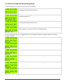
4.3.1 Questions asked with Any Storage Mode
Enter the current site name, up to 15 characters long. You should always enter a site to
help distinguish between different data collection sessions. Note that the full alphabet
plus numbers and punctuation can be used.
Enter in the first line of information, up to 15 characters long. This Info line is provided
in addition to the Site string and can be left blank if desired.
A second line of information is also optional.
Enter in the correct time, in military format. If the time shown is correct, simply press
the ENTER key to accept it and go to the next configuration option.
Enter in the correct date. If the date is correct, simply press Enter to continue. Note
that the format may also be DD-MM-YY or YY-MM-DD depending on the date format
you selected in the Configure System option.
Enter the correct day of the week by pressing the arrow keys and toggling through the
standard weekdays.
The choices are Sun, Mon, Tue, Wed, Thu, Fri, and Sat.
With Raw or Binned Storage.
With Count.
4.3.2 Lane Grouping Questions
The Unicorn Limited has the ability to group lanes together inside of the counter prior to storing them in memory. You
could, for example, group lanes 1 through 4 together and store only their summed values in memory. This has the
advantage of reducing the amount of memory that is being used, and the disadvantage of eliminating the individual
lane totals.
Lane Grouping Questions are only asked if you are in Binned or Count Mode and you have selected Yes for the “Ask For
Lane Groupings” question in the Configure System option.
Select from 0 to 4 groups. Selecting 0 disables lane grouping. Selecting 1 puts all lanes
into one group. Selecting 2 or more causes the counter to ask questions where you
specify which lanes go into which groups.
If you select 2 or more groups, the counter asks you the following question for each group:
Unicorn Limited User Manual
Page 15
Where Y is the Group number and (Lanes) is which lanes are currently assigned to this
group. To assign a lane to this group, simply press the number key corresponding to the
lane number. To un-assign a lane from this group, press the number key again. Note:
You must assign at least one lane to each group. You cannot assign lanes to the group,
which have already been assigned to another group.
Lane grouping is only visible when you retrieve the collected data. Monitoring the lanes and all other functions are not
affected by lane grouping.
Lane grouping does not affect the type of data collected (such as Axle Classification or Speed Classification) but simply
adds several lanes classification values together to look as if all vehicles were in a single lane.
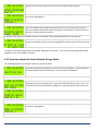
4.3.3 Questions asked with Raw Per Vehicle Storage
The following Questions are asked for each lane you have enabled:
Enter the appropriate information for this lane, up to 15 characters. This Information is
normally used to indicate lane direction. You may leave this field blank.
Used if Directional has been created. If Directional mode has not been enabled, this will
not be asked.
Enter the appropriate information for this lane, up to 15 characters. This Information is
normally used to indicate lane direction. You may leave this field blank. If directional
has been enabled, this is the passing lane of Lane 1 and Lane 4 is the passing lane of
Lane 2
Set this value to indicate the spacing in between your sensors. This can be set from 0.4
feet to 99.9 feet. See Section 3.4 Sensors for recommended spacing.
Use the arrow keys to select which type of Raw Per Vehicle Data you wish to collect
(Section 2). Choices are Normal Raw Data, Enhanced Raw, Raw with Bins, and Enhanced
& Bins.
Press ENTER to select.
The system will now go into a lane test and “Waiting for Any Vehicle…” will be displayed. Each lane may now be tested
with the data displayed on the LCD as vehicles pass over the Road Tubes.
From here, the system asks the final start questions, See Section 4.3.7.
Page 16
Unicorn Limited User Manual
4.3.4 Questions asked with Binned Storage Mode
The following questions are asked for each lane you have enabled.
Enter the appropriate information for this lane, up to 15 characters. This information is
normally used to indicate lane direction.
Use the arrow keys to toggle between Yes and No. If it is enabled, a directional lane is
created (see Section 2).
Enter the appropriate information for this lane up to 15 characters. This information is
normally used to indicate lane direction.
Set this value to indicate the spacing in between your sensors. This can be set from 0.4
feet to 99.9 feet. See Section 3.4 for recommended spacing.
The following questions ask which bins you want to enable for data collection. At least one bin must be enabled. All
bins may be enabled; however, it is suggested the user read Appendix B (Memory Usage) to determine if enough
memory is available.
Select Yes or No for this option to turn on or off this type of data collection.
Select Yes or No for this option to turn on or off this type of data collection.
Select Yes or No for this option to turn on or off this type of data collection.
Select Yes or No for this option to turn on or off this type of data collection.
Select Yes or No for this option to turn on or off this type of data collection.
Select Yes or No for this option to turn on or off this type of data collection.
Unicorn Limited User Manual
Page 17
Select Yes or No for this option to turn on or off this type of data collection.
Select how many different interval lengths (1-5) during the day the Unicorn Limited will
use when collecting data.
If only one different interval is selected, the Unicorn Limited asks:
Enter the Length of the record interval you want to use. You may enter any value of
hours or minutes, which divide evenly into 24 hours or 60 minutes. 01:00 (one hour) or
00:15 (15 minutes) are most common.
If more than one interval is selected, the Unicorn Limited will ask the following questions for each interval:
The first interval defaults to start at 00:00 (midnight) and cannot be changed. The
Unicorn Limited will ask for start time and Length of interval for each successive interval.
The Unicorn Limited will now display the message “Waiting for Any Vehicle”. Once a vehicle has passed and the data
viewed is correct, press ENTER to continue.
4.3.5 Questions asked with Count (Volume) Storage Mode
The following questions are asked for each lane you have enabled.
Enter the appropriate information for this lane, up to 15 characters. This information is
normally used to indicate lane direction. You may leave this field blank.
If you are setting an odd numbered lane, the counter asks:
Choices are Normal, Direction, or Subtract. Selecting anything other than Normal will
indicate that you are using this lane in conjunction with the next lane to get count. This
causes the counter to automatically configure the next lane to be the same as this lane.
Select Yes to automatically divide the total count by two.
After the lanes have been entered, the following question is asked:
Select how many different interval lengths (1-5) during the day the Unicorn Limited will
use when collecting data.
If only one different interval is selected, the Unicorn Limited Asks:
Page 18
Unicorn Limited User Manual
Enter the Length of the Record Interval you want to use. You may enter any value of
hours or minutes, which divide evenly into 24 hours or 60 minutes. 01:00 (one hour) or
00:15 (15 minutes) are most common.
If more than one interval is selected, the Unicorn Limited will ask the following questions for each interval:
The first interval defaults to start at 00:00 (midnight) and cannot be changed. The
Unicorn Limited will ask for the start time and length for each successive interval.
After entering the interval information, the Unicorn Limited will show a test sensor
screen. As data is collected, the count for each lane entered will be shown. Note that
the Unicorn Limited is NOT collecting or storing data at this point – it is testing the lanes
for proper setup. Press ENTER to continue.
4.3.6 Questions asked with Sensor Storage Mode
The following question is asked for each lane enabled:
Enter the appropriate information for this lane, up to 15 characters. This information is
normally used to indicate lane direction.
The screen will display “Waiting for Any Sensor…”. The system is not collecting or storing data. It is for the user to
confirm lane setup and configuration. Once several sensors have been activated and the data is satisfactory, press
ENTER to continue.
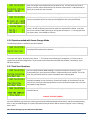
4.3.7 Final Start Questions
You can choose between NOW, Midnight, or Date/Time options of starting. If you
choose Date/Time, the system will request a Time and a Date to be entered. This is the
hour, day, and month that the Unicorn Limited will start collecting data.
You can choose between Never, 24 Hours, Date/Time. Never will continuously run until
manually shutdown (or out of memory); 24 hours will simply run for 24 hours from the
time of start; and if you select date/time the Unicorn Limited will request entry of a time
and a date to stop collection.
After you press ENTER the counter will start collecting and storing data at the next
selected interval.
<DO NOT TURN OFF POWER>
Once the ENTER key is pressed, the system goes into sleep mode (the display will be blank), and has started collecting
data. If you press ENTER again, the system will wake up and you will be able to choose any option in the “Collecting
Data” menu.
Note about selecting any start time other than Now:
Unicorn Limited User Manual
Page 19
The counter will go ahead and put you in the Collecting Data Menu, even though you may have selected to start
collecting at midnight or at some future time and date. This condition is called “Preset Active”, since the counter has
been preset to start collecting at a future time. While in Preset Active mode, no file is open and no data is being stored
in memory. However, you can still monitor collection, however, to verify the sensor configuration is working.
Note about collecting Binned or Count Data:
These two modes both use Record Intervals. The Unicorn Limited will NOT start collecting data until the beginning of
the next record interval. For example: The record interval is set to 15 minutes, you tell the counter to start Now when
it is 10:53:00. The counter will not start storing data until 11:00:00, because the counter is waiting for the start of a
new interval. This mode is called “Preset Active” (see above).
4.4 Show Status
The Show Status option allows display of the Unicorn Limited System Status. This should always be performed prior to
Starting Collection to ensure that there is enough memory free to collect files. From the menu press “2” and the
display will show:
Press ENTER to show system status.
First, the counter displays the amount of memory in the system:
Displays the total amount of memory in your counter and how much is left for use.
Next, how many files are in the counter’s memory are displayed:
“N” is the number of files currently in memory.
If there are no files, the screen displays:
Next the current time and date are shown:
The current time, date, battery voltage and counter internal temperature are displayed.
Note that the date will be displayed in the currently selected format. The time and date
can only be programmed from the Start Collecting sequence.
Page 20
Unicorn Limited User Manual
4.5 Delete Files
NOTE: Deleting Files from Memory Can NOT be undone!
The Delete Files option allows you to delete any or all files currently in memory. Press “3” from the menu and the
display will show:
Press ENTER to begin deleting files.
If there have been no files created in memory, the counter shows:
If files have been created, the display will show:
“N” is the number of files currently residing in memory. By pressing the arrow keys the
options of “All Files” or “All Retrieved Files” may be selected.
If “All Files” is selected, the display will show:
This message is the safety for deleting files. Use the arrow keys to toggle the answer to
Yes.
This is the safety for file deletion. If set to Yes, pressing ENTER will DELETE ALL FILES!
If “Retrieved Files” is selected, and no files have been retrieved, the display will show:
If files have NOT been retrieved, the display will show:
If retrieved file are in memory, the display shows:
Use the arrow keys to toggle to Yes to delete the files.
Once you press enter the following is displayed. Once this process is started, it can NOT be stopped.
Unicorn Limited User Manual
Page 21
The Unicorn Limited will go back to the main menu Delete Files screen when finished.
4.6 View Lane Totals
This option allows you to view the total amount of vehicles (Raw, Binned, and Count Storage Modes) that have
occurred from the last time you started collection to the last time you Stopped Collection.
When you select this option, a screen will appear similar to the following.
OR
A & B are the lane numbers of enabled lanes and X & Y are the total vehicles or sensor activations. If you used a preset
time (such as Start At Midnight) then these lane totals will reset at the end of the preset time. Also, using In-Day times
will reset the lane totals at the beginning of each In-Day period. Daily or Weekly files, however, do not reset the lane
totals.
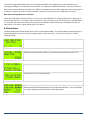
4.7 Configure System
Configure System will set the system configuration for installation. Press the number “5” from the main menu and the
display will show:
Press ENTER to begin system configuration.
This asks which storage mode you require. The choices are: Bin Classification, Count
(Volume), Sensor Activations, and Raw (each vehicle).
This asks which date format you require. Options are: MM/DD/YY, DD/MM/YY, and
YY/MM/DD.
This asks if you want to stop collecting data when the memory is full. Select Yes and the
counter will delete the oldest file in order to make space for new data files. If you select
No, the Unicorn Limited will stop collecting when the memory is full.
The user may select to create new files Manually, Daily, or Weekly. Manually means
that the counter will only create a file when you specifically tell it to. Daily means the
counter will automatically create a new file each day at midnight. Weekly means the
counter will automatically create a new file once per week, typically Sunday at midnight.
If you select Weekly files, you will be asked:
Page 22
Unicorn Limited User Manual
Select the day of the week that should become the FIRST day of your weekly file.
Your choices are Sun, Mon, Tue, Wed, Thu, Fri, Sat.
This option enables or disables the Lane Grouping Function. If you select No, then Lane
Grouping is disabled and the counter will not ask questions pertaining to it in the Start
Collecting option.
The following questions are only asked if either Binned or Raw Storage mode has been
selected:
Requests either U.S. (Feet and MPH), or Metric (Centimeters and KPH) format.
This option is used to select what the counter should do with sensor miss information.
Sensor misses occur when a vehicle does not cross both sensors (see lid instructions on
Unicorn Limited field Unit for a description of each Sensor Miss or SnMis Code). View
Only will display sensor misses on the screen when monitoring, but not store these
misses in memory. View & Store displays the misses and stores them into memory for
later retrieval. Note that storing sensor misses in memory does use up memory that
could be used for data. Disabled causes the counter to ignore sensor misses.
This option determines the longest spacing between any two axles to be allowed when
collecting Raw or Binned data using two axle sensors. The counter uses this length to
determine where the end of a vehicle is, and the start of a new vehicle begins. Most
trucks do not exceed 35’ between axles, and most vehicles do not travel closer than 35’
to each other. You should change this value if you have many tailgating vehicles, which
have short axle spacings (such as rush hour car traffic), or if you have trucks with very
long spacings between axles. Note that the longer the spacing, the greater chance two
vehicles close to each other will be counted as one vehicle or classified incorrectly.
Select at what voltage you want the counter to warn you about the battery being low.
Use the left arrow key to decrease the voltage and the right arrow key to increase the
voltage. Factory default is 6.0 with a .02 volt offset. We recommend you leave it at this.
4.8 Cold Restart
Cold Restart will perform the same function as removing backup power. The system will restart with all memory
cleared. Note that time and date, along with All Configuration parameters WILL BE LOST. Do not use this option if the
system contains any data that has NOT been retrieved for use. ALL DATA WILL BE LOST.
Note: We recommend you contact Diamond Traffic Products Support Desk BEFORE a Cold Restart is performed.
Doing a Cold Restart maybe useful if you notice the counter is not working correctly. There are about one million
possible configuration combinations that can be keyed into the counter. Some of these programs make no sense from
a data collection point (but we do not have programming space to prevent them from being entered). If you key one
of these in accidentally, the counter will not operate correctly until a cold restart is performed.
Note: We recommend you contact Diamond Traffic Products Support Desk BEFORE a Cold Restart is performed.
Press “6” from the menu and the screen will show:
Unicorn Limited User Manual
Page 23
Press ENTER to select the option.
If you are SURE you want to do this, use the arrow keys to toggle to Yes.
Press ENTER
The system has now been completely reset to the factory defaults.
4.9 Stop Collecting
Stop Data Collection is the one way to return to the Start Collecting Data menu. Press “1” from the menu and the
display will show:
Press ENTER to select the option.
Use the Arrow keys to toggle to Yes. Pressing ENTER will close the current file.
“N” is the file number. Pressing ENTER again will return the user to the Start Collecting
Data menu.
4.10 Monitor Lanes
Monitor Lanes allows the real-time monitoring of lanes. This option is intended for the user to monitor traffic to
ensure the installation is working properly. Press “4” from the menu and the display will show:
Press ENTER to select the option.
Page 24
Unicorn Limited User Manual
4.11 Monitoring Raw or Binned Data Collection
The counter displays this when first waiting for a vehicle:
As a vehicle crosses the installation site, the display will show the vehicle’s recorded information:
Indicates a vehicle passed in Lane 1 at 10:25am. It had 5 axles, was going 54 miles per
hour, and the spacing from the first to the second axle was 12.8 feet. If you are
collecting Binned data, the axle spacing will be replaced by one or more bin classification
numbers that the vehicle matched, based upon your selected bins.
While monitoring, you may press the following keys:
1 or 2 –Tells the counter to only display the lane number you press.
0 – tells the counter to display all lanes.
CLEAR – Aborts and returns to the menu.
SPACE – Freezes the display, this allows you to view a vehicle for a longer period of time. Press SPACE again to
un-freeze the display.
Left or Right Arrow keys – Allows you to see other spacings. Press either arrow key again and the screen will
return to the original display. These keys work even when the Freeze key (Space) has been pressed.
If an asterisk character appears before the lane number, this indicates that data storage has not actually started yet,
and the vehicles shown are not being stored in memory until the next selected interval begins. This mode is called
“Pre-Set Active”.
4.12 Monitoring Count Data Collection
The counter displays the first four count lanes you have enabled. Note the counter only displays the lanes you have
enabled.
An asterisk on the screen indicates that data storage has not started yet.
While monitoring data collection, the following keys can be used:
0 – If just Testing Lanes (i.e. from the Start Collecting option) this key “zeros” all totals.
CLEAR – Aborts and returns to the menu.
Unicorn Limited User Manual
Page 25
5. Keypad Operation Examples
The following section gives seven examples using the keypad of the Unicorn Limited. The first five give examples of
setting up the counter to collect Raw Data, Monitoring Data, Stopping Collection, Collecting Binned, and Count Data.
The last one is an example of Deleting Files.
Note that these examples are not complete descriptions. You should refer back to Section 4 for more in-depth
information.
As the examples are worked through, files will be created in memory. The last example will show how to delete
retrieved or all selected files. If you get lost, or a step is missed, simply return to the beginning by using the clear key.
IMPORTANT – In many cases the Unicorn Limited will skip certain questions during setup if there is only one possible
answer for it.
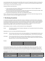
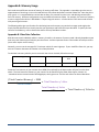
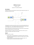
Example Site – The following Diagram gives you an example site setup. It will be used as reference in the examples
that follow.
Scenario: Two Road Tubes are installed on State Highway 58.
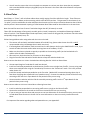
5.1 Configuring the System
This section is an example of configuring the system. Once the system is configured, it does not need to be done again
unless a cold restart is done or the mode of collection (Raw, Binned, and Count) needs to be changed. It will be used
for each example that follows this one. It is recommended to try variations of configuring the system in a test
environment to become familiar with the Unicorn Limited.
Turn on the Power Switch. The system will perform a self test and then show the following screen:
Press “5”.
Press the ENTER key.
Page 26
Unicorn Limited User Manual
Select the required mode (Raw, Binned, Count, or Sensor) by using the arrow keys; press
ENTER. Which mode you select depends on which of the following examples you are
following.
Select this format by pressing ENTER, or select a different format with the arrow keys
and then press ENTER.
The following questions are only asked if either Binned or Raw Storage mode has been
selected:
Requests either U.S. (Feet and MPH), or Metric (Centimeters and KPH) format.
Since we want the counter to stop when memory is full, press ENTER to keep the default
value of No.
To get the counter to STOP when the memory is full, Select No, otherwise, 1st in, 1st out and data collection will
continue.
Press ENTER to leave at Manually.
Press ENTER to leave at NO.
Press the ENTER key to see Sensor Misses on the screen, but not to store them in
memory.
Press ENTER to keep the default value.
Press ENTER to keep the default value.
The menu has rotated through the Configure System Option and returned to the Start
Collection Menu. Now that the system is configured, press “1”.
You are now ready to continue with one of the collecting data examples.
Unicorn Limited User Manual
Page 27
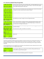
5.2 Collecting Raw Data
This section will give an example of collecting Raw Data. Use Example 5.1 first to configure the system to collect Raw
Data. After that example, the display should show:
Press ENTER.
Note the blinking cursor on the character line. Use the keypad (Section 3.1) to enter in a
Site ID; for example: HWY 58.
Press ENTER when done.
Enter in the first line of information, up to 15 characters long. This Info line is provided
in addition to the Site string and can be left blank if desired. For this example, we have
entered “System Test”
Optionally, you can enter a second line of Information. Press ENTER when done.
Note the position of the cursor in the first digit of the time. Start entering the time with
Hour, Minutes, and then Seconds, using Military Format. For example, 15:30:00 would
be 3:15pm and zero seconds. Press ENTER when done.
Note once again the position of the cursor & that the date is in the format set in
Configure System. Enter the date and press ENTER when done.
Use the arrow keys to toggle to the correct day. Press ENTER when done
Press the number on the keypad which corresponds to the lanes you want to enable.
For this example, press “1”.
Press ENTER.
Use the keypad to enter the direction or some other piece of information about the lane,
for example: “Westbound”.
Page 28
Unicorn Limited User Manual
Press ENTER when done.
Since it is a two lane highway with a good chance of vehicles passing, press the right
arrow key to toggle the option to Yes. Press ENTER when done.
Since we created a directional lane, we can now enter information about that lane. For
example: “Westbound Pass”. Press ENTER when done.
Since our example road tubes are at 4.0’, type 0, 4, 0 and press ENTER when done. This
setting must match the actual physical spacing on the road.
Press the arrow to change the option to Enhanced Raw (Section 2.2) and press ENTER
when done.
At this point, the next vehicles to cross over the Road Tubes will be shown as test
vehicles. The first vehicle to Cross in Lane #1 will show something like:
The asterisk (*) means no data is being stored yet. This mode is called “Pre-Set Active”.
Wait for vehicles in both lanes to pass, and if data is correct, press “ENTER”.
Since we want to start collection right now, press ENTER.
Since we are running a test file, press ENTER.
Press the ENTER key. The counter is now collecting data as vehicles pass. The display
will shut off. This is normal, intended to use less of the battery. Press ‘ENTER’ to reactivate the display, if needed.
Raw data collection has started. After a few vehicles have passed, you may want to try the Stop Collection example
(Section 5.6) and then retrieve the data following the instructions in the Centurion Users Manual.
Unicorn Limited User Manual
Page 29
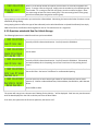
5.3
Collecting Binned Data
This section will give an example of collecting Binned Data. Use example 5.1 first to configure the system to collect
Binned Data. After that example, the display should show:
Press Enter.
Note the blinking Cursor on the character line. Use the keypad (Section 3.1) to enter in a
Site ID. For example: HWY 58.
Press ENTER when done.
Optionally, you can enter a line of information for example: System Test.
Press ENTER when done.
Optionally, you can enter a second line of information. Press ENTER when done.
Note the position of the cursor in the first digit of the Time. Start entering the time with
the Hour, Minute, and then Seconds using Military Format. For example 15:30:00 would
be 3:15pm and zero seconds. Press ENTER when done.
Note the position of the cursor, and that date is in the format set in the “Configure
System” option. Enter the current date, and press ENTER.
Use the arrow keys to toggle to the correct day. Press ENTER when done.
Press the number on the keypad that corresponds to the lane(s) you want to enable. For
example, press 1.
Press ENTER.
Page 30
Unicorn Limited User Manual
Use the keypad to enter the direction or some other piece of information about the
lane, for example: Westbound.
Press ENTER when done.
Since it is a two lane highway with a good chance of vehicles passing, press the right
arrow key to toggle the option to Yes. Press ENTER when done.
Since we created a directional lane, we can now enter information about that lane. For
example: Westbound Pass.
Press ENTER when done.
Since our example road tubes are at 4.0’, type 0, 4, 0 and press ENTER when done. This
setting must match the actual physical spacing on the road.
Change this to “Yes” by pressing arrow key and then press ENTER.
Press the arrow key to toggle to “Yes” and press ENTER when done.
Leave this at No by pressing ENTER.
Leave this at No by pressing ENTER.
Leave this at No by pressing ENTER.
Leave this at No by pressing ENTER.
Unicorn Limited User Manual
Page 31
Leave this at No by pressing ENTER.
For this example, two intervals will be set. The first from midnight to 05:00 for early
morning traffic, and the second from 05:00 to midnight for daytime traffic. You may
setup different intervals, just follow the same basic steps. Press “2” then press ENTER.
Note the cursor is positioned in the second line, showing 00:15. This is the length of the
interval starting at 00:00 (midnight). Change this interval length to 1 hour by pressing
0,1,0,0 then press ENTER when done.
Note that the cursor is blinking on the first line. Enter 05:00 for the time to start the
second time period. Press ENTER again to leave the intervals at 00:15. The final result is
that our time intervals for Binned data will be 1 hour from midnight to 5am, and 15
minutes for the rest of the day.
At this point, the next vehicle to cross the road tubes will show as a test vehicle. The
first vehicle to cross in Lane #1 will show something like the following:
The asterisk (*) means no data is being stored yet. Wait for vehicles in both lanes to
pass, and if data is correct, press ENTER.
Since we want to start collection right now, press ENTER.
Since we are running a test file, Press ENTER.
Press ANY key. The counter is now collecting data and the display will go blank. Note
that it will not start until the beginning of the next even interval (if past 05:00 AM, the
next even 15 minutes).
Binned data collection has started. After a few record intervals have passed you may want to try the Stop Collection
Example (Section 5.6) and then retrieve the data following the instruction in the Centurion Software manual.
Page 32
Unicorn Limited User Manual
5.4 Collecting Count Data
This section will give an example of collecting Count Data. Use Example 5.1 first to configure the system to collect
Count Data. After that example, the display should show:
Press Enter.
Note the blinking cursor on the character line. Use the keypad (Section 3.1) to enter a
Site ID. For example: HWY 58.
Press ENTER when done.
Optionally, you can enter a line of information. For example: System Test.
Press ENTER when done.
Note the position of the cursor in the first digit of the time. Start entering the Time with
Hour, Minute, and then Second using Military Format. For example, 15:30:00 would be
3:15pm and zero seconds. Press ENTER when done.
Note the position of the cursor; and that date is in the format set in “Configure System”
option. Enter the current date, and then press ENTER.
Use the arrow keys to toggle to the correct day. Press ENTER when done.
Press the number on the keypad which corresponds to the lanes you want to enable. For
this example, press “1” and “2.”
Press the ENTER key.
Use the keypad to enter the direction or some other piece of information about the lane.
For example: Westbound.
Unicorn Limited User Manual
Page 33
Press ENTER when done.
Since we have set our Road Tubes up for Lane Subtraction, change this to Subtract with
the arrow keys and press the ENTER key.
Press ENTER when done.
Use the keypad to enter the direction or some other piece of information about the lane.
For Example: Eastbound.
Press ENTER when done.
For this example, one interval length will be set. Press “1”, and then press ENTER.
Change this interval length to 1 hour by pressing 0,1,0,0. Press ENTER when done.
The asterisk (*) indicate that the counter is not recording data into memory yet. If “n” is
incrementing correctly for all lanes enabled the press ENTER.
The asterisk (*) means no data is being stored yet. Wait for vehicles in both lanes to
pass, and if count is correct, press ENTER.
Since we want to start collection right now, press ENTER.
Since we are running a test file, press ENTER.
Press the ENTER key. The counter is now collecting data.
Count data collection has started. Note that the counter will not actually begin recording intervals until the beginning
of the next interval period, in this example the next even hour (11:00:00). After a few record intervals have passed you
may want to try the Stop Collection example (Section 5.6) and the Retrieve the data following the Instructions in the
Centurion Users Manual.
Page 34
Unicorn Limited User Manual
5.5 Monitoring Traffic & Viewing Status
This section gives an example of monitoring traffic while the Unicorn Limited is collecting data. This does not affect
data collection – it allows the user to monitor the Unicorn Limited to ensure that the system is functioning properly as
the user has set it up.
To start, you will need a Unicorn Limited, which has been installed and is collecting data. If you have followed any of
the last 3 examples, it will work fine. If not, follow one of the examples for installation and return to this section.
While collecting, the screen is normally blank indicating the counter is in a special “Sleep” mode, press ENTER to wake
it up and the display will show:
Press “5” key, or use Arrow keys to scroll to this selection.
Press ENTER to select option.
The next screen depends on the type of data you are collecting. For Raw and Binned data you will see:
When the next vehicle data is collected, the display will show the vehicle’s information
on the screen.
If you are collecting Count Data, your screen will show something like:
The actual lane numbers and totals depend on your current setup. As each sensor is
activated, the new totals for that Lane are displayed.
When finished monitoring, press the ENTER or CLEAR key to return to the menu.
Use the arrow keys (or press “2”) to scroll to the “Show Status” option.
Press ENTER.
Note that the memory messages will depend upon how much memory is installed in
your system and how much has been used. Refer to Appendix B for memory usage
information. Press ENTER.
This shows that the file is open and collecting data. Press ENTER.
Unicorn Limited User Manual
Page 35
Show the current time and date and press ENTER.
You have stepped through the Show Status Option. Press CLEAR. The display will go
blank. The Unicorn Limited is still collecting data and is now in a low power sleep mode.
<DO NOT TURN OFF POWER>
5.6 Stop Collection
This section gives an example of Stopping Data Collection. For information on file retrieval, please read the Centurion
Users Manual. Note that the counter must be setup to start data collection before you can stop collecting.
While collecting, the screen is normally blank indicating the counter is in a special “Sleep” mode. Press ENTER to wake
it up and the display will show:
Press ENTER.
Press either arrow key to toggle to “Yes”. Press ENTER.
Note that the file # is the current open file. If you were using Raw Data and you have
gone through the examples in this manual, it should show File #1. If you have collected
other data files, the file # shown will vary depending upon how many times you have
started new files. Press ENTER.
Note that the Unicorn Limited has automatically returned to the Start Collecting Menu
from where you started the examples. However, if you select the “Show Status” option
and ENTER through the messages, you will note that there are now files recorded in
memory. These files can be retrieved by the Centurion Software. Power may now be
turned off to the unit without losing any data stored in the files.
5.7 File Deletion
If all the examples have been followed, several files will have been created in memory. To remove unwanted files, use
the Delete File Option, available from either While Collecting or Not Collecting menus. If the system is in sleep mode,
press ENTER to wake the counter up. The Display will show:
Press the Arrow keys (or press “3”) until the display shows:
Press ENTER to select the option.
Page 36
Unicorn Limited User Manual
This screen requests confirmation from the user before the Unicorn Limited will delete
ALL file. If you want to delete ALL files, press an arrow button one time.
By pressing ENTER you are instructing the Unicorn Limited that you want to delete ALL
files. This new version does not allow you to select which files to delete.
After pressing ENTER, the screen will change to the following with an increasing
percentage indicator.
This screen shows that the Delete Files Process was complete.
Should there be no files to delete the following screen appears:
No files in Flash Memory to delete.
5.8 Collecting Data Using Lane Grouping
This section will show you how to enable the Lane Grouping function to collect Grouped Count Data on four lanes. To
collect grouped Binned Data, simply change the storage mode. First, follow example 5.1 to configure the system to
collect count data. Stop when you get the following question in the Configure System option.
Press the right arrow to select “Yes” then press ENTER to continue. Follow through the
remainder of 5.1 to finish the system configuration.
Now that Lane Grouping has been enabled, go to example 5.4 (Collecting Count Data) and follow all instructions until
you get to the following screen, then follow the below instructions:
Press the number on the keypad which corresponds to the lanes you want to enable.
For example, press 1, 2, 3, and 4.
Press ENTER.
This question allows you to select the number of groups, press “2”.
Unicorn Limited User Manual
Page 37
Press ENTER.
You will next need to assign the lanes you want to belong to each group.
Press 1 and 2 to assign lanes 1 and 2 to Group #1.
Press ENTER.
Press 3 and 4 to assign lanes 3 and 4 to Group #2.
Press ENTER to continue. Go back to the 5.4 to complete starting the counter to collect
count data.
That’s it! When data collection is finished and you retrieve the data from this counter, you will actually end up with
only two lanes of data (Lanes 1 & 2). Lane #1 (which is actually Group #1) will contain the combined total of physical
Lane #1 and Lane #2 data. Lane #2 (which is actually Group #2) will contain the combined totals of physical Lane #3
and #4 data.
6. In-Day Times
The Unicorn Limited has a special function called In-Day Times. In-Day Times are time periods in the day that you wish
to Start and Stop collecting data. This is similar to the Daily files function, except you can Start and Stop collection at
several different times during a 24 hour period. The basic purpose of this function is to handle very large data
collection requirements where you only have enough memory in the counter to store part of a day.
A day can have up to five (including zero) Start/Stop periods. You do not need to collect data during the entire day nor
do you need to make sure that these periods of collection follow each other exactly. For example, you could collect
data from 8am to noon, and then from 4pm to 8pm. The rest of the day no data would be collected and the counter is
considered to be in the Preset Active Mode (see Section 4.3.6).
In-Day times will work with any type of data collection (Raw, Binned, Count, or Sensor). If collecting Binned or Count
Data and you do not specify an In-Day Stop Time at the end of an interval, then you will lose the data of the current
interval unless the next In-Day Start time is the same as the Current In-Day Stop time.
For example, suppose you are collecting Binned data in 1 hour intervals and you have specified an In-Day period from
10:00 to 11:30 and a second In-Day Period from 11:30 to 14:00. The counter will close the current file at 11:30 and
then open a new file immediately because the next In-Day period starts at 11:30. The current Binned data interval
(which is from 11:00 to 11:59) will be preserved and will be written to a second file as its first interval even though the
file was opened at 11:30. This is identical to retrieving the open file data when it is in the middle of an interval.
On the other hand, had you specified the second period to start at 12:00, all of the data from the 11:00 to 11:59
interval will be lost and the first interval written to the new file will start at 12:00.
Page 38
Unicorn Limited User Manual
You should be aware that In-Day times do not take effect until the counter first begins data collection according to the
Start Mode (which can be Now, Midnight, or at Date & Time). Until the very first file is opened according to all other
counter settings, the In-Day Times will have no effect.
To Setup a Counter to use In-Day Times:
1. Link to the counter with Centurion software and go to the main link screen. Select the Configure System
option and setup all counter system parameters.
2. Select the In-Day Times function and select the number (0 to 4) and the times of all In-Day Time periods. Note
that you must enter the times in order from the earliest to the latest.
3. Select the Start Collecting function and setup, test, and begin data collection.
That’s it. After the very first file is opened, the counter will then begin to check the In-Day Time settings to see if any
specific time periods in the day have been tagged for data collection.
7. Site Naming Conventions
It is important to note that the Station ID referenced in Centurion’s Database is the Same Site ID that is referenced in
our counters and classifiers. Each location which you collect data from needs to have a unique name that CAN NOT be
used elsewhere for data collection purposes. If you have a site along a state route for example, make the assumption
that there WILL be multiple locations that COULD be used to collect data at. In doing this, you will minimize the
headache of trying to figure out why some sites will not import due to data overlays.
While setting up a counter or classifier, you will be asked to fill out the following field:
Site ID:
This field will provide the basis of how data is displayed once in imported into Centurion for processing
and reporting purposes.
Depending on your Unit, you may be asked the following questions:
Info Line #1:
This line can be used for either the first set of GPS coordinates or for larger geographical location such
as a town, county, parish, park, or some other identifiable grouping. This line is purely informational.
Info Line #2:
This line can be used for either the second set of GPS coordinates or for further identifying Info Line
#1. For example, if Line 1 was used to represent a town, Line #2 could be used to specify a county that
the town is a part of. This line is also purely informational.
Example:
Site ID
Info Line #1
Info Line #2
Hwy 58
Greenwaters
Eastbound
Site ID
Info Line #1
Info Line #2
Hwy 58
Diamond Peak
Westbound
This information looks good. However, there could be several additional data collection sites on Hwy 58. In fact, in
this example there will only be one site inside of the Centurion Database with the name of Hwy 58. Centurion will
show a data overlay error while attempting to import the second site stating that a site already exists with that name.
To remedy this problem before it starts, we need a more specific Site ID to start with. In the above examples this would work
more clearly:
Site ID
Info Line #1
Info Line #2
Greenwaters
Eastbound
Hwy 58
Unicorn Limited User Manual
Site ID
Info Line #1
Info Line #2
Diamond Peak
Westbound
Hwy 58
Site ID
Info Line #1
Info Line #2
Odell Entrance
Diamond Peak
Hwy 58
Page 39
This information is not trying to tell you how to name your sites. We are explaining how the naming convention works
inside of Centurion, the software program that most of our users use to retrieve data and process reports with.
We hope that this information is useful in reducing the confusion in how the Centurion Database uses Site ID’s.
Appendix A. Trouble Shooting
This section is intended as a guide towards installation troubleshooting. It is in no way intended for the service or
repair of any type of Unicorn Limited counter.
Some basic problems can occur during operation. Generally, they will be some small error in setup or sensor
installation. Listed are some basic problems and possible solutions. If you cannot solve an installation problem, or if
you find a new solution to an old problem, please call Diamond Traffic Products. We are glad to help solve any type of
installation problem or receive new installation information.
Problem
Tubes are installed to collect Raw or Binned Data, but errors keep occurring in data collection.
Solution
Are the tubes the same length? Is the physical spacing consistent and matching what you used during
configuration/setup? Are they stretched tight (both the same amount if using two per lane) across the road way? Are
there holes in the tubes (you can check this by plugging the tube and putting it underwater)? Is the end of the tube,
which is not being connected to a Unicorn Limited, plugged properly?
Problem
I’ve installed tubes to collect raw vehicle data, but I keep getting errors. I’ve checked the “Test Sensor” option, and the
tubes are functioning.
Solution
Are the tubes in the correct order? Remember, the tubes must be connected in sequence depending on your lane
assignment and configuration. Check the tables in Section 2.1 for confirmation. You may have a lane installed
backwards. Another possible problem is bidirectional traffic. Do you have the Directional Option enabled?
Problem
I have installed a Unicorn Limited in a busy roadway. The counter has stopped collecting data when I arrive.
Everything seems to be working.
Solution
Check the Show Status option. Is the memory full? You may need to retrieve the data from the counter more often.
Page 40
Unicorn Limited User Manual
Appendix B. Memory Usage
Each mode uses a different amount of memory for storing traffic data. This appendix is intended to give the user an
approximation of how long a Unicorn Limited field unit may collect data before retrieval of data files. Note that this is
only a guide. It is recommended to retrieve data as often as is practical from the units. and deleting retrieved files
from the memory. Different configurations may store different amounts of data. For example, the amount of memory
to store a single 2 axle vehicle in Raw Mode is 7 bytes using axle sensors. A 5 axle vehicle in the same mode will take
13 bytes using axle sensors.
The following tables give you formulas for calculating how much memory any particular storage mode might take.
Simply find the table that most closely matches your application and follow the steps described. To quickly find our
counters Total Memory, refer to Section 4.4 and use the top Total Mem number.
Appendix B.1 Raw Data Collection
Raw data stores each individual vehicle in memory; therefore, the amount of memory used is directly dependent upon
how many and of what type of vehicles pass the sensors. Another important factor is the number of axles per vehicle
(more axles require more memory).
Generally, you can use the average of 2.75 axles per vehicle for most highways. If your site differs from this, you may
wish to increase or decrease this number in the example below.
To calculate how many vehicles you can store with the Unicorn Limited, follow these steps:
Sensor Configuration
Normal Raw Data
Enhanced Raw Data
Raw Data with
Bins
Enhanced & Bins
Axle-Axle
8.5
12.5
13.5
17.5
Divide the Total memory of your counter minus 2000 (for overhead) by the base number of bytes from the chart
above. The total amount of memory in your counter can be found using the Show Status option, Section 4.4.
A standard Unicorn Limited contains 8.5 Megabytes, which gives over 1 million axle strikes for Normal Raw Data.
Unicorn Limited User Manual
Page 41
Appendix B.2 Binned Data Collection
Binned data stores data as the total number of vehicles in each bin category in every record interval. The three most
important factors are: which bin categories are enabled, what the record interval length is, and how many lanes are
enabled.
Follow the steps below to calculate how long your Unicorn Limited can collect data with any given setup.
Using the table below, calculate the base number of bytes in a single record period, for a single lane. This is done by
adding up all the different modes you have enabled (Axle, Speed, Length, etc...). The table gives two values. The first
is the default number (if you have not modified the bin table configuration). The second is a formula you can use to
calculate the number if you have put your own bin table specifications. Note that “SnMis Bins” are created if you
select “View & Store” from the “SnMis Storage Mode?” question in the Configuration System option.
Axle
Class
Speed
Class
Length
Class
Gap
Class
Headway
Class
Speed &
Length
Speed & Axle
SnMis
Bins
Default
26
32
26
16
16
416
416
8
User
Defined
2 x Bins
2 x Bins
2 x Bins
2 x Bins
2 x Bins
(2xSpd Bin) X
Length Bin
(2xSpd Bin) X
Axle Bin
For example, if you were collecting Axle & Speed classification, your base number of bytes would be 26 + 32
would equal 58 Bytes
Take your base number of bytes and multiply it by the number of enabled lanes (including directional lanes).
Thus, if you had Lane #1 enabled with directional, you would have two enabled lanes. This number is the base
number for ALL LANES.
Adjust the base number for all lanes by adding 1 for each type of classification you have enabled, except
SpeedxLength and SpeedxAxle. If you enabled SpeedxLength, add in the number of Length Bins. If you
enabled SpeedxAxle, add in the number of Axle Bins. For example, if you enabled Axle, Speed, and SpeedxAxle
classification, you would add 1 + 1 +13 + base number for all lanes. See Appendix D for bin definitions and
there defaults. This would be the Total Number of bytes per record interval.
The next step is to take the total number of bytes in your Unicorn Limited, subtract 2000 (overhead), and
divide it by the total number of bytes per record interval. This gives you the NUMBER OF RECORD INTERVALS
THE MEMORY WILL HOLD. The total number of bytes in your Unicorn Limited can be determined by using the
Show Status option, see Section 4.4.
Next, multiply the total number of record intervals the memory will hold by the record interval length (in
minutes). This gives you the total length of time in minutes the Unicorn Limited will record into memory.
You are basically done. You can calculate the number of hours by dividing the time in minutes by 60, or the
number of days by dividing the time in minutes by 1440.
The above system works only if you do not have different record interval lengths during the day.
Page 42
Unicorn Limited User Manual
1.
2.
3.
4.
5.
6.
Unicorn Limited User Manual
Page 43
Appendix B.3 Count Data Collection
Count data stores the total number of vehicles or the total number of axles that have crossed the sensors for a given
time period. The two factors to consider are: how many lanes are enabled, and what the record interval length is?
Follow the steps outlined below to calculate how long a Unicorn Limited will collect count data into memory:
Multiply the total number of enabled lanes by 2.
Add one to the number. This is the Total number of bytes per record interval.
The next step is to take the total number of bytes in your Unicorn Limited, subtracting 2000 (for overhead),
and divide it by the total number of bytes per record interval. This gives you the number of record intervals
the memory will hold. Total number of bytes in your Unicorn Limited can be determined by using the Show
Status option, Section 4.4.
Next, multiply the total number of record intervals the memory will hold by the record interval length (in
minutes). This gives you the total length of time, in minutes, the Unicorn Limited will record into memory.
You are basically done. You can calculate the number of hours by dividing the time in minutes by 60, or the
number of days by dividing the time in minutes by 1440.
The above system works only if you do not have different record interval lengths during the day.
If Interval Length is in minutes divide Total Record Time by 1440 this will give you the number of days the Unicorn
Limited can record, if necessary, divide this number by 365 to receive the total number of years.
Appendix B.4 Sensor Data Collection
Sensor data storage will store in memory each individual sensor activation. Therefore, the more sensor activations you
have, the quicker memory will run out.
Follow the steps below to calculate how many sensor activations can be stored in the memory of the Unicorn Limited.
Page 44
Find out the total amount of memory in the Unicorn Limited. This can be determined using the Show Status
option.
Subtract from the total amount of memory 2000 bytes (for overhead).
Divide by 8. This will be the amount of sensor activations which can be stored in memory.
Unicorn Limited User Manual
Appendix C. Plugs and Connectors
This section describes the physical hardware connections for connectors on the Unicorn Limited.
Unicorn Limited 9 pin Female Serial Interface Cable
Unicorn Limited 9 Pin Connector – Male
Unicorn Limited 9 Pin Connector – Female
#1 – Receive Data (RXD)
#3 – Transmit Data (TXD)
#2 – Carrier Detect (DCD)
#4 – Data Terminal Ready (DTR)
#3 – Data Terminal Ready (DTR)
#6 – Data Set Ready (DSR)
#4 – Ready to Send (RTS)
#8 – Clear to Send (CTS)
#5 – Serial Port Enable (ENA)
#5 – Signal Ground (GND)
#6 – Signal Ground (GND)
(Shield)
#7 – Not Connected
#8 – Transmit Data
#2 – Receive Data (RXD)
#9 – Clear To Send (CTS)
#7 – Ready to Send (RTS)
Appendix D. Default Bin Tables
This appendix describes the default bin categories that are used with the Unicorn Limited. These “Bins” are used to
total up all vehicles meeting a predetermined set of criteria. Note that this information is ONLY used if you configure
the Unicorn Limited to collect data in its Binned Mode. Raw, Sensor, and Count Modes do not bin data.
Default Axle Bin Classification Table (Scheme – ‘F’, FHWA)
Bin Number
#1
#2
#3
#4
#5
#6
#7
#8
#9
#10
#11
#12
#13
Unicorn Limited User Manual
Axle Range
2
2-4
2-5
2-3
2-5
3
4
3-4
5
6-10
5
6
7-13
Bin Category Name
Motorcycles
Passenger Cars (with or without Trailer)
Other two Axle, 4 tire Vehicles (with or without Trailer
Buses
Two Axle, Six tire, Single Trailer Trucks
Three Axle, Single Unit Trucks
Four axle, single Unit Trucks
Four or less axle, Single Trailer Trucks
Five Axle, single Trailer Trucks
Six or more Axles, Single Trailer Trucks
Five Axle, Multi-Trailer Trucks
Six Axle, Multi-Trailer Trucks
All Other Vehicles
Page 45
Default Speed & Length Bin Classification Table
Bin Number
#1
#2
#3
#4
#5
#6
#7
#8
#9
#10
#11
#12
#13
#14
#15
#16
Speed Range
0.0 – 19.9 MPH
20.0 – 24.9
25.0 – 29.9
30.0 – 34.9
35.0 – 39.9
40.0 – 44.9
45.0 – 49.9
50.0 – 54.9
55.0 – 59.9
60.0 – 64.9
65.0 – 69.9
70.0 – 74.9
75.0 – 79.9
80.0 – 84.9
85.0 – 89.9
All Other Speeds
Length Range
0.0 – 5.9 feet
6.0 – 10.0 Feet
10.1 – 14.9
15.0 – 19.9
20.0 – 24.9
25.0 – 29.9
30.0 – 39.9
40.0 – 49.9
50.0 – 59.9
60.0 – 69.9
70.0 – 79.9
80.0 – 89.9
All Other Lengths
Default Gap and Headway Bin Classification Table
Bin Number
#1
#2
#3
#4
#5
#6
#7
#8
Page 46
Gap Bin Time
00:00:03.00
00:00:10.00
00:00:15.00
00:00:20.00
00:00:30.00
00:01:00.00
00:02:00.00
All Other Gaps
Headway Bin Time
00:00:03.00
00:00:10.00
00:00:15.00
00:00:20.00
00:00:30.00
00:01:00.00
00:02:00.00
All Other Headways
Unicorn Limited User Manual
Appendix E. Road Tube Problems & Solutions
This appendix discusses the various problems that road tubes can cause. Road Tubes present their own unique set of
problems for automatic vehicle classifiers and counters. Being aware of these potential problems before installing
your road tubes can greatly reduced the frequency of these problems.
This appendix divides each problem (or “error”) into a separate section, and then lists the known causes of problems.
Appendix E.1 Missed Axles
Missed axles are the most frequent errors seen. They are caused, very simply, by the hardware (air switch) inside the
counter not reporting an actuation of the road tube when there is one. Some of these reasons for this are as follows:
Speed and Spacing – The Air Switch in the Unicorn Limited is undoubtedly the best in the business; however,
even it is limited to 30 activations per second, or about 33ms per activation. If a second strike of the road tube
occurs faster than 33ms, then the Air Switch will not report the second activation. Does this ever happen? Yes.
Take for example a car towing a 2 axle travel trailer at 65mph. A travel trailer typically has a spacing of 2.5 feet
between axles, and 65mph is about 95 feet per second. Therefore, how long does it take between the first
road tube hit by the travel trailer, and the second? This is (2.5ft/ (95ft/sec)) 26ms. The Air Switch would not
report the second axle of the travel trailer and this axle would be missed by the Unicorn Limited.
Lifted Wheels – Some trucks have an optional axle which may be raised slightly off the ground (to save on
tread ware). The Unicorn Limited will probably miss it, but sometimes it can show up as an error if human
observation data is being compared to the counter and the observer is not aware that the wheel is lifted.
Bouncing Vehicles – Although uncommon, roads with dips or other irregular surface features can cause some
truck axles to bounce slightly. This can occasionally lead to missed axles. Note that the Unicorn Limited looks
at both sets of road tube activations, so this problem is minimized.
Improper Road Tubes or Installation – The type, length, and method of installation of your road tubes can lead
to increasing the number of missed axles. Always plug the end of the tube with a suitable device (unless the
road tube is shorter than 25 feet, and then DON’T plug it); always plug the road tube onto the counter nozzle
all the way; always use an approved brand, size, and type of material for all of your road tubes; don’t over
stretch the road tubes because the diameter shrinks the more you stretch it.
Weak Signal with Longer Road Tubes – Very simply, the longer the road tube, the farther the “sound” of an
axle striking the road tube has to travel. Make sure you use road tube lengths as recommended in the next
section.
Sound Wave Interference – To understand why this is a problem, you should understand that the Unicorn
Limited Air Switch (like all air switches) uses a “sound wave” to detect an axle hit. This wave is very similar to a
water wave, in that it starts at a point and moves down the road tube to the round piezo disk sensor in the Air
Switch. It travels down the road tube at the speed of sound, which is about 767mph at 68 degree Fahrenheit,
or 1125 feet per second. The force of this “wave” of sound bends the piezo disk in the counter which causes a
voltage spike to be generated. It is this voltage spike which the Unicorn Limited detects as an axle strike on the
road tube.
The following example shows how very close axle hits (such as with tandem axles on a truck) can actually interfere with
each other and cause a missed axle.
1. Assume you have a 50’ road tube stretched across a single lane of traffic. The road tube has been
stretched 50” to make it tight. The end of the tube on the roadway is plugged and the other end is
secured to a Unicorn Limited.
2. A 5 axle single trailer truck traveling 55mph crosses the road tube.
3. The first axle is detected with no problem.
4. The second axle (the first axle of first tandem pair) hits the road tube. This causes FOUR sound waves
to be generated, TWO from each tire.
5. The left tire will send two sound waves from it (1 in each direction) and the right tire will send two
Unicorn Limited User Manual
Page 47
6.
7.
8.
9.
10.
11.
waves from it as well. The sound waves look something like the following: -------<< A - B >>------------------<< C - D >>---------(to Unicorn Limited) Each letter represents a sound wave and the arrow next to
the letter shows the direction that the sound wave is traveling.
At this point the following things will happen: Sound “A” will travel to the end of the road tube and be
absorbed by the plug. Sound “B” and “C” will travel towards each other, collide and be seriously
weakened. Sound “D”, however will be uninhibited and travel down the road tube towards the Air
Switch on the Unicorn Limited. Since all of the sound waves except “D” have been destroyed, we will
only talk about sound wave “D” for the rest of this section, and it will be called the Wave.
The road tube has been stretched about 50”, so it is now 54.16’ long, Presuming the truck is in the
center of the lane (lane being 12 feet wide) and the truck is 8 feet wide, the Wave should start at the
44’ mark.
The Wave will travel down the road tube towards the Unicorn Limited and contact the Air Switch in
about 39mn (ms stands for milliseconds, or thousandths of a second)
After the Wave hits the Air Switch, it will bounce back and return up the road tube towards the
vehicle. Thus, we have a weakened returning wave going back up the road tube.
The next axle on the truck hits the road tube about 56ms after the first 4.5ft spacing typical, on a
55mph vehicle. Once again, another Sound Wave “D” is generated and travels down the road tube
towards the Air Switch.
At this point we have the following: ----D2 >>----------<<D1---------Unicorn Limited
One wave traveling down and one weaker wave returning. They will, of course, collide into each other
at some point in the road tube, weakening both waves so that the second wave is too weak to register
as an axle strike.
The question then becomes, if this is causing missed axles, why does a shorter road tube work better? If you take a 30’
road tube, stretch it 50”. Sound wave “D” will start about the 24’ mark and therefore will take only 21ms to reach the
Air Switch. Similarly, Sound Wave “D” will only take 21ms to return to the starting point (at the 24’ mark). This makes
the total time only 42ms for the first Sound Wave “D” to strike the Air Switch and return to the starting point. This
time is BEFORE the 56ms time it takes for the next axle to hit. Therefore, the first Sound Wave “D” is past the point of
origin and cannot interfere with the next axle strike.
In summary, you are better off using shorter road tubes for faster speed vehicles. You are also better off using shorter
road tubes for vehicles which have closer axle spacings (such as truck tandem axles). To minimize missing axles and
maximize accuracy we suggest using the following road tube lengths:
Page 48
Speed
Road Tube Length
0 – 25 mph
26 – 35 mph
36 – 45 mph
46+ mph
30 Ft
40 Ft
50 Ft
60 Ft
Unicorn Limited User Manual
Appendix E.2 Extra Axles
This error, while not frequent, does happen. It is almost always a problem with the actual road tube installation, or
with the road surface. Causes of extra axles are listed below:
Road Tube Bounce (Slap) – Since the road tubes are made of flexible rubber, they move when they are hit.
Depending on how tightly they are stretched, how far apart the anchors to the roadway are, and how heavy
the vehicles crossing the tubes are, the road tube may move only slightly, or may move a lot. When a tire hits
the road tube normally, the Air Switch is activated by the sound of the tire. If the road tube is moved a lot, it
will return quickly enough to its original position and may “Slap” the road with enough force to actually
“sound” like another axle. This error is minimized by the fact that the Air Switch will not re-activate for at least
33ms, and the road tube should be stabilized by then (but not always). You can also help this problem by
taping the road tube to the road at short intervals along its length.
Rutted Pavement – Do not install road tubes over badly rutted pavement. This will cause the road tube to
bounce wildly when driven over by heavy vehicles. If you must install the road tubes in rutted pavement, tape
them down heavily.
Road Tube Not Perpendicular to Traffic – This error (usually only at slow speeds) is caused by a vehicle not
hitting the road tubes squarely. If the vehicle is going slow enough, the left tire (or tires) and the right tire (or
tires) will cause an individual activation. This problem is most commonly seen at intersections, where vehicles
are turning across the road tubes at slow speeds.
Appendix E.3 Bad Speed and/or Length
This problem is infrequent, but can occur sometimes when the counter misses axles. For example, assume a 2 axle
vehicle with an 8’ between axles is traveling @60mph, striking two road tubes spaced 8’ apart. The spacings and
timings occurred as below:
1. Road Tube #1 hit by first axle at 10:00:00.00000.
2. Road Tube #2 and #1 hit almost simultaneously by first and second axles at 10:00:00.09090. Counter missed
the Road Tube #2 hit (for whatever reason).
3. Road Tube #2 hit by second axle at 10:00:00.18181.
Since the counter waits for the first hit on #1, and the first hit on #2 to determine the speed, the speed will be
determined by the second road tube #2 hit. This gives (8ft/.18181sec) 44ft/sec, or 30 mph. This is only ½ the actual
vehicle speed! Since the speed is calculated wrong, the counter will also give an incorrect length value for the vehicle.
Note that this error is really caused by a missed axle; the only difference is that Unicorn Limited was still able to create
a vehicle from the data, so it gave the values it could.
Appendix E.4 SnMis (Sensor Miss) for Entire Vehicle
Like the previous error, this problem only occurs as a result of missed axles. “SnMis” (for Sensor Miss) is the Unicorn
Limited’s way of indicating that it did not have enough sensor data, or got sensor data not in the right order, to make a
vehicle. Once a sensor miss occurs, the Unicorn Limited blocks out all further sensor activations on that lane for 1
second.
SnMis #1 – the counter only got a road tube #1 strike, with no further road tube activations. This can happen if
a vehicle hits the first road tube, but misses the second, while changing lanes.
SnMis #2 – the counter only got a road tube #2 strike, without first getting a road tube #1 strike. This like
SnMis #1, can happen if a vehicle crosses into the lane but misses road tube #1.
SnMis #3 – is an over-speed or under-speed vehicle, and can optionally be used to indicate vehicles which only
hit road tube 1 and road tube #2 once, with no further activations. Note that the counter will normally turn
these types of activations into two axle vehicles with the axle length equal to the sensor spacing.
Unicorn Limited User Manual
Page 49
Appendix E.5 One Vehicle Shown as Two
This error is normally caused by a vehicle with axle spacing greater than the maximum axle spacing setting in the
Configure System option. The counter defaults to 35.0’. This value can be increased or decreased.
If you increase this value, you run the risk of counting vehicles traveling close together as one vehicle (two tailgating
cars become one vehicle, usually turned into a four axle, per Scheme – F Class #8).
This error can also be caused by missed axles. The Unicorn Limited only resets its time-out value after each axle hit. If
you miss some and the counter does not reset its value, then the vehicle will be ended prematurely.
*Contact DTP for assistance w/Tailgate Detect function in Firmware Ver. 1.xx & higher
Appendix E.6 Road Tube Setup
For Proper Road Tube Setup, please refer to our “Road Tube Installation Guide” located on our website.
http://support.diamondtraffic.com/knowledgemanager/
Page 50
Unicorn Limited User Manual