1
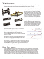
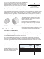
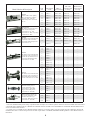
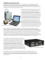
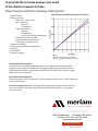
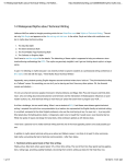
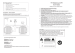
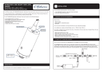
Technical &
Sizing Bulletin for
Meriam LFEs
Laminar
Flow
Elements
What they are...
Meriam Laminar Flow Elements are gas volume rate of flow differential producers operating on capillary flow principles.
They are available in a wide range of types and sizes and are ideally suited to many flow measurement and calibration
applications. NIST traceable certificates of calibration from Meriam’s ISO 17025 Flow Lab are standard.
LFEs are applicable over wider flow ranges than
conventional types of differential producers. The fact that
their flow versus differential pressure curve approaches
linearity makes this wider range possible. In many
applications one Meriam LFE can cover a range of flow
which would otherwise require several venturis, nozzles
or orifice plates. Their low range accuracy is limited only
by the flow stability and the readability of the differential
pressure sensing instrument. The selection of readout
or secondary instrumentation is most important in the
overall performance and installed accuracy of Meriam
LFEs.
Some typical applications of Meriam LFEs include:
combustion air flow to internal combustion engines, fan
and blower calibration, leak testing, cylinder head port
air flow, and testing of automobile components. LFE’s are
also used to calibrate other flow metering devices such
as variable area meter, thermal anemometers, orifices,
nozzles, etc. Contact us for application assistance.
Standard LFE calibration accuracy is ± 0.72% to ±0.86% of Reading
(not % of Full Scale; See Fig. 1) traceable to the National Institute of
Standards and Technology (NIST). Special calibration accuracy of ±
0.5% of Reading or better is optional. Rigid construction and lack
of any moving parts make the LFE calibration stable. Only physical
damage or particulate deposition in the element will cause a
calibration shift. Cleaning and recalibration is typically recommended
every 12 to 18 months.
The nearly linear relationship between produced differential pressure
(DP) and flow rate results in impressive turndown ratios of 20:1, 50:1 or
even greater depending largely on the accuracy and resolution of the
Fig. 1. Compare % FS to % Reading
Standard models are available to measure as little as 0.2 SCCM (5.9 E-06 SCFM) to as
much as 2250 SCFM of air flow at standard conditions. Custom models for as much
as 15,000 SCFM of air are available. Stainless steel or aluminum materials make
LFEs compatible with most gases. Flow rate of gas mixtures can also be measured
provided the percentages of component gases and mixture properties are known.
How they work...
Laminar Flow Elements are designed to take advantage of the Hagen-Poiseuille relationship for energy loss under
laminar flow conditions. In simplified terms, this relationship states that if a flow tube or capillary has small enough
diameter relative to its length, the difference in pressure between the tube’s inlet and outlet will be linearly proportional to the flow rate through the tube. Flow in the gas supply pipe may be turbulent, transitional, or laminar.
By using small capillaries, either individually or in a bundle (or matrix), the LFEs induce laminar flow through each
capillary. Combining this feature with a sufficient capillary length results in a nearly linear relationship between DP
and flow rate.
1
LFEs are viscosity dependent devices. When laminar flow exists, the fluid tends
DP
to behave as if it were divided into layers. Since viscosity is a measure of a
fluid’s resistance to change of shape, then as layers of fluid move over each
other, system energy is lost due to friction between the layers. The system
energy loss is observed as DP across the inlet and outlet of the LFEs matrix.
ID <<< LENGTH
Due to the dependence of the DP on viscosity (a function of temperature and
Application of Hagen-Poiseuille Law
gas media) and the velocity of the flowing gas, LFEs measure actual volumetric
Application of Hagen-Poiseuille Law
flow rate. This makes it necessary to measure gas temperature and inlet pressure in order to calculate mass or standard volumetric flow rates.
Laminar Flow Elements can be fabricated from several materials. Housings are typically stainless steel or aluminum and serve
to hold the matrix of capillaries together in a stable configuration. They also provide process and DP connections. Process
connections are available in tapered thread, straight thread with O-ring, VCO, hose or flange varieties. DP connections are
made via tapered thread, straight thread with O-ring or hose barbs. The LFE matrix can be made from individual stainless
steel tubes or windings of stainless steel foil. More exotic materials may be available when fluid compatibility is a concern.
The DP generated across the matrix responds quickly – within
16 milliseconds – to changes in flow velocity. Response time of
the meter (LFE and readout device) is generally limited to the
capabilities of the DP readout device.
The Meriam Matrix...
Permanent pressure loss is associated with LFE use. Since the
DP across the LFE matrix is a measure of system energy lost to
overcoming friction between laminar flow layers, all produced
DP is permanently lost pressure. This is usually not a problem,
however, due to the way LFEs are sized. Full scale flow rates are
limited so that 8 to 10 inches of water column is the maximum DP
produced. When even less permanent loss can be tolerated, an LFE
can be oversized to produce less DP at the required flow rate or the
correct size LFE can be made with a shortened matrix length.
the heart of the element
Meriam LFEs channel flow through a myriad of minute parallel capillary passages. Velocity is maintained at about the same
as in the supply pipe. The capillary dimension is reduced sufficiently to produce laminar flow from the normally occurring
turbulent gas stream. The drawings above represent end views of the “matrix” at the heart of Meriam LFEs. Each round
or triangular shaped passage measures only a few thousandths of an inch in effective diameter while measuring several
inches in length. They are therefore considered to be “capillary” passages.
As a gas flows through the matrix, friction created causes a pressure drop. The amount of this drop is determined by
measuring the pressure differential across the matrix. The stainless steel matrix is formed and fused into a mechanically
rigid unit. This geometric integrity provides permanent calibrations; there are no moving parts. Only deposition of particles
or physical damage to the matrix will cause calibration shift.
In some smaller sizes of Meriam LFEs, bundles of capillary tubes are used instead of a matrix.
Differential Pressure and Pressure Loss
Meriam LFEs are normally rated for maximum
flow at 4 or 8 inches of water differential. There
is no recovery of pressure differential from a
Laminar Flow Element matrix. Filters and inlet
and outlet configurations increase the total
pressure drop and must be considered when
pressure loss considerations are critical.
Model
Metering Pressure Drop
at Full Flow
(in inches of water)
Total Pressure Drop
at Full flow
(in inches of water)
50MK10 / 50MT10
4
4
50MJ10 / 50MT10
8
8
50MW20 / 50MT20
8
8
50MH10
8
8
50MY15
8
8
50MR2 or 50MC2
8
12
50MR2-F or 50MC2-F
8
12
2
How To Size Laminar
Flow Elements
To determine the proper size of a Laminar Flow Element
it is necessary to determine the flow range in equivalent
standard cubic feet per minute (SCFM*) of air. The range is
then compared to SCFM* ranges shown on Page 8. Follow
one of the four examples below.
I. AIR FLOW IN SCFM AT STANDARD
CONDITIONS OF 29.92” Hg. Abs. AND 70°F.
SCFM = Standard cubic feet per minute.
ACFM = Actual cubic feet per minute.
CFM = Cubic feet per minute.
When the flowing gas is air and the operating pressure
and temperature are at 29.92” Hg. Abs. and 70°F (standard
conditions), the Laminar Flow Element can be selected
directly from the capacity chart.
NOTE:
SCFM
=
at
29.92”
Hg. Abs.
70°F
II. AIR OR GAS FLOW IN SCFM AT OTHER THAN
29.92” Hg. Abs. AND 70°F.
SCFM* =
When the flow is given in another standard of SCFM of air or
some other gas, and the operating pressure and temperature
are not at 29.92” Hg. Abs. and 70°F, then the equivalent SCFM
air flow at 29.92” Hg. Abs. and 70°F must be computed as
though the laminar flow element were flowing air under
(Meriam) standard conditions. To do this, use the equation
below:
SCFM* = SCFM X
29.92
Tg
X
Pg
530
X
ACFM
=
at
29.92”
Hg. Abs.
70°F
CFM
at
29.92”
Hg. Abs.
70°F
The equivalent amount of air in SCFM, if the flowing
conditions were air, flowing through the Laminar
Flow Element under a pressure of 29.92” Hg. Abs.
and at 70°F (Meriam standard conditions).
SCFM = Standard Cubic Feet per Minute of gas referenced to
base conditions of 70°F and 29.92” Hg. Absolute.
Pg = Pressure of the flowing gas in inches Hg. Abs.
Tg = Temperature of the flowing gas in degrees Rankin (°R).
(°R = 460 + Temperature in °F)
µg = Viscosity of the gas at the flowing temperature, in micropoise
µg
181.87
III. AIR OR GAS FLOW IN ACFM OR CFM UNITS.
3. Standard Liters per Minute (SLPM)
SLPM
SCFM =
28.316
When the air or gas flow is given in other than SCFM*, then
the SCFM value must be computed from the equations below.
The sizing of a laminar flow element can then proceed as in
Example 2.
4. Pounds per Minute (PPM)
PPM
SCFM =
Density**
1. Cubic Feet per Minute (CFM)
(Pg)
SCFM = 17.714 * CFM
(Tg)
5. Pounds per Hour (PPH)
PPH
SCFM =
60 x Density **
or Actual Cubic Feet per Minute (ACFM)
(Pg)
(Tg)
2. Standard Cubic Centimeters per Minute (SCCM)
SCCM
SCFM =
28316
SCFM = 17.714 * ACFM
*17.714 =
530
T Std.
=
29.92
P Std.
** At standard conditions (29.92” Hg. Abs. & 70ºF)
228 Sg Pg Diff.
µg
RD = Reynoldʼs Number
Sg = Specific gravity of the flowing gas (based on air = 29)
Pg = Pressure of the flowing gas in inches Hg. Abs.
Diff = Differential pressure calculated for the laminar flow element
selected
µg = Viscosity of the gas at the flowing temperature, in micropoise
Calculation of RD for conditions as presented in example 2:
IV. OBSERVANCE OF REYNOLD’S NUMBER FOR
THE LAMINAR FLOW ELEMENT SELECTED.
RD =
To maintain laminar flow with linearity through the LFE,
consideration must be given to The Reynolds number for the
maximum flow condition. Meriam LFEs will produce linear
flow characteristics when the Reynolds number is 150 at 4”
differential and 300 at 8” differential.
It should be pointed out that true linearity will not be retained
at elevated Reynolds number. However, a calibration made at
the operating condition will be fully usable and repeatable.
To calculate the approximate Reynolds number for the
LFE selected, use the equation:
RD =
3
228 x 0.138 x 32.78 x 6.545
201.13
= 35.8
Basic Sizing
Equation
SCFM* = ACFM x
OR
SCFM* = SCFM x
µg
181.87
x
Diff. Pressure*
SCFM
* Catalog Rating for Laminar Flow Element Selected
Select a Laminar Flow Element for the following conditions:
The gas flowing is AIR at a flow rate of 15 SCFM.
The pressure of the flowing AIR is 29.92” Hg. Abs.
The temperature of the AIR is 70ºF.
Since this flow is at standard condition, the Laminar Flow Element
can be selected directly from the capacity chart .
The Laminar Flow Element selected in this example would be a
Model 50MW20-1½.
To compute the approximate differential pressure that this
selection would develop, use the equation:
SCFM (calculated) X
For the above example
Diff. Pressure =
8
15 x
= 5.454” H2O Differential
22
A check should be made for Laminar Flow by calculating the
Reynoldʼs Number. See section IV.
Upon examining the ratings for the various Laminar Flow Elements
we can see that the Model 50MJ10-10 will handle this flow since it
is rated at 1.6 SCFM* @ 8” H2O differential pressure.
A check should be made for Laminar Flow by calculating the
Reynoldʼs Number. See Section IV.
EXAMPLE 2:
Select a Laminar Flow Element for the following conditions:
The gas flowing is HELIUM at a flow rate of 1.25 SCFM.
The pressure of the HELIUM gas is 1.4 PSIG (=32.781” Hg. Abs.)
The temperature of the HELIUM is 90°F (=550°R)
The viscosity of HELIUM @ 90°F is 201.13 micropoise.
From the Basic Sizing Equation, calculate the equivalent SCFM*
air flow as:
29.92
550
201.13
x
x
=1.309
32.78
530
181.88
Gas Properties at standard conditions of
29.92” Hg. Abs. and 70ºF
Density
(lb/ft3)
µ Viscosity
Micropoises
Specific
Gravity
Air
0.0749
181.87
1.000
Argon
0.1034
225.95
1.380
Helium
0.0103
193.9
0.138
Hydrogen
0.0052
88.41
0.0695
Nitrogen
0.0725
175.85
0.968
Oxygen
0.0828
203.47
1.105
Carbon Dioxide
0.1143
146.87
1.526
Gas
EXAMPLE 3:
Select a Laminar Flow Element for the following conditions:
The gas flowing is HELIUM at a flow rate of 1.184 ACFM.
The pressure of the HELIUM gas is 1.4 PSIG (=32.781” Hg. Abs.)
The temperature of the HELIUM is 90°F. (=550°R)
The viscosity of HELIUM @ 90°F is 201.13 micropoise.
From the Basic Sizing Equation equation for actual cubic feet per
minute, calculate the equivalent SCFM* air flow as:
SCFM* = 1.184 x
29.9
Tg
x
Pg
530
Diff. Pressure =
EXAMPLE 1:
SCFM* = 1.25 x
µg
181.87
201.13
=1.309
181.87
NOTE: Ref. NBS Technical Note 564 for Gas Viscosity Data
Using this value, proceed to select and LFE as in Example 2.
The differential pressure expected would be equal to:
EXAMPLE 4:
Select a Laminar Flow Element for the following conditions:
The gas flowing is ARGON at a flow rate of 0.9 SCFM.
The pressure of the flowing ARGON is 20 psig (=70.64” Hg Abs.).
The temperature of the ARGON is 60ºF (=520°R).
The viscosity of ARGON at 60º F is 222.51 micropoise.
The specific gravity of ARGON at standard conditions is 1.380.
8
= 5.23” H2O
0.7
If we now compute the Reynold’s number for these conditions we
find that:
228 x 1.380 x 70.64 x 5.23
RD =
= 522
222.51
From our equivalent air flow equation (See Section II):
This Reynold’s Number is too high even though the flow rate
calculation gives us an acceptable differential pressure. Therefore,
we will have to size the LFE with a larger size, or the Model
50MJ10 Type 10. The same calculations will give us a differential
of approximately 2.29 and a Reynold’s Number of 228. This model
would be acceptable for the application.
Diff. pressure = .458 x
29.92 520 222.51
SCFM* = .09 x
x
x
=.458
70.64 530 181.87
This flow rate could be determined by Model 50MJ10-11 which
has a rating of 0.7 SCFM* @ 8” H2O.
4
Model Number & Description
50MK10
Utilizes stainless steel capillary
tubes cemented into a stainless
steel body. Inlet, outlet and
differential pressure connections
are 1/4”.
Model 50MJ10
All stainless steel unit with fused
matrix. Differential pressure
connections are 1/4”. Line
connections 1/2” NPT, except Type
9 which has 3/4” NPT.
50MW20
All stainless steel welded unit with
fused matrix. Line connections
are threaded. Differential pressure
connections are 1/4”.
50MH10
All stainless steel welded unit with
fused matrix. Line connections are
tapered ends (no threads) for hose
connection. Differential pressure
connections are 1/4” NPT.
50MY10
All stainless steel welded unit with
fused matrix. Line connections are
150 lb ANSI flanges. Differential
pressure connections are 1/4” NPT.
50MR2
Aluminum housing for low
pressure applications. Line
connections are 150 lb ANSI
flanges. Differential pressure
connections 1/4” hose barb.
50MC2 Aluminum housing for
low pressure applications. Inlet
and outlet are for hose type
connections. Differential pressure
connections 1/4” hose barb.
Line
Size
NPT tapered
thread
FISO 7/1
tapered thread
SAE J1926
straight thread
w/ O-ring
DIN3852 Part 2
straight thread
w/ O-ring
1/4”
50MK10-8
50MK10-8MT
50MK10-8S
50MK10-8MS
1/4”
50MK10-7
50MK10-7MT
50MK10-7S
50MK10-7MS
1/4”
50MK10-6
50MK10-6MT
50MK10-6S
50MK10-6MS
1/4”
50MK10-5
50MK10-5MT
50MK10-5S
50MK10-5MS
1/4”
50MK10-4
50MK10-4MT
50MK10-4S
50MK10-4MS
1/4”
50MK10-3
50MK10-3MT
50MK10-3S
50MK10-3MS
1/4”
50MK10-2
50MK10-2MT
50MK10-2S
50MK10-2MS
1/4”
50MK10-1
50MK10-1MT
50MK10-1S
50MK10-1MS
1/2”
50MJ10-14
50MJ10-14MT
50MJ10-14S
50MJ10-14MS
1/2”
50MJ10-13
50MJ10-13MT
50MJ10-13S
50MJ10-13MS
1/2”
50MJ10-12
50MJ10-12MT
50MJ10-12S
50MJ10-12MS
1/2”
50MJ10-11
50MJ10-11MT
50MJ10-11S
50MJ10-11MS
1/2”
50MJ10-10
50MJ10-10MT
50MJ10-10S
50MJ10-10MS
3/4”
50MJ10-9
50MJ10-9MT
50MJ10-9S
50MJ10-9MS
1”
50MW20-1
50MW20-1MT
50MW20-1S
50MW20-1MS
50MW20-1 1/2
50MW20-1 1/2MT
50MW20-1 1/2S
50MW20-1 1/2MS
2”
50MW20-2
50MW20-2MT
50MW20-2S
50MW20-2MS
1”
1 1/2”
50MH10-1
-----
-----
-----
1 1/4”
50MH10-1 1/4
-----
-----
-----
1 1/2”
50MH10-1 1/2
-----
-----
-----
2”
50MH10-2
-----
-----
-----
3”
50MH10-3
-----
-----
-----
4”
50MH10-4
-----
-----
-----
5”
50MH10-5
-----
-----
-----
6”
50MH10-6
-----
-----
-----
8”
50MH10-8 (x)
-----
-----
-----
10”
50MH10-10 (x)
-----
-----
-----
12”
50MH10-12 (x)
-----
-----
-----
16”
50MH10-16 (x)
-----
-----
-----
2 1/2”
50MY15-2 1/2
-----
-----
-----
3”
50MY15-3
-----
-----
-----
4”
50MY15-4
-----
-----
-----
5”
50MY15-5
-----
-----
-----
6”
50MY15-6
-----
-----
-----
8”
50MY15-8 (x)
-----
-----
-----
10”
50MY15-10 (x)
-----
-----
-----
12”
50MY15-12 (x)
-----
-----
-----
16”
50MY15-16 (x)
-----
-----
-----
2”
50MR2-2
-----
-----
-----
4”
50MR2-4
-----
-----
-----
6”
50MR2-6
-----
-----
-----
8”
50MR2-8
-----
-----
-----
2”I.D.
50MC2-2
-----
-----
-----
4”I.D.
50MC2-4
-----
-----
-----
6”I.D.
50MC2-6
-----
-----
-----
8”I.D.
50MC2-8
-----
-----
-----
NOTES:
1. The flows and differential pressure rating of production units are subject to a variation of plus or minus 10% from the nominal values listed above.
2. Each LFE unit is calibrated with air to Meriam flow standards which are traceable to the National Bureau of Standards. Meriam calibration flow
curves are furnished with each unit.
3. A special service is available for those Meriam LFE units which are governed by quality programs requiring periodic recalibration. The Special
Calibration Procedure A-33544 is designed to meet the basic requirements of 10CFR50, ANSI-Z540-I & ML-Q-9858A. Contact Meriam direct for
information.
5
Nominal Air Flow Range
(29.92” Hg. Abs. & 70ºF)
Nominal Air Flow Range
760 MM Hg. Abs. & 21.1ºC)
Max DP
MM H2O
SCFM*
PPM
Max. DP
In. H2O
Pipe Size
CC/MIN*
LPM*
Kg/M
0.00019
1.42 x 10⁻⁵
4”
1/4”
5.38
0.00538
6.44 x 10⁻⁶
0.00062
4.64 x 10⁻⁵
4”
1/4”
17.5
0.0175
2.10 x 10⁻⁵
101.6
0.000124
9.28 x 10⁻⁵
4”
1/4”
35.1
0.0351
4.21 x 10⁻⁵
101.6
0.0025
1.87 x 10⁻⁴
4”
1/4”
70.8
0.0708
8.48 x 10⁻⁵
101.6
0.0046
3.45 x 10⁻⁴
4”
1/4”
130
0.130
1.56 x 10⁻⁴
101.6
0.0081
6.07 x 10⁻⁴
4”
1/4”
229
.229
2.75 x 10⁻⁴
101.6
0.0149
0.00112
4”
1/4”
422
.422
5.06 x 10⁻⁴
101.6
0.046
0.00344
4”
1/4”
1300
1.30
0.00156
101.6
0.10
0.00749
8”
1/2”
2830
2.83
0.00339
203.2
0.18
0.0135
8”
1/2”
5100
5.10
0.0061
203.2
0.38
0.0285
8”
1/2”
10700
10.8
0.0129
203.2
0.70
0.0524
8”
1/2”
19800
19.8
0.0237
203.2
1.60
0.120
8”
1/2”
45300
45.3
0.0543
203.2
3.00
0.225
8”
3/4”
85000
85.0
0.102
203.2
7.5
0.562
8”
1”
2.12 x 10⁵
212
0.254
203.2
22
1.65
8”
1 1/2”
6.23 x 10⁵
623
0.746
203.2
40
3.00
8”
2”
1.13 x 10⁶
1130
1.357
203.2
5
2.12 x 10
212
0.254
203.2
4.53 x 10⁵
453
0.543
203.2
6.51 x 10⁵
651
.780
203.2
1.13 x 10⁶
1130
1.35
203.2
2.55 x 10⁶
2550
3.05
203.2
4.53 x 10⁶
4530
5.43
203.2
7.08 x 10⁶
7080
8.48
203.2
1.02 x 10⁷
10200
12.2
203.2
1.81 x 10⁷
18100
21.7
203.2
2.83 x 10⁷
28300
33.9
203.2
4.07 x 10⁷
40800
48.8
203.2
6.37 x 10⁷
63700
76.3
203.2
1.69 x 10⁶
1700
2.03
203.2
2.55 x 10⁶
2550
3.05
203.2
4.53 x 10⁶
4530
5.43
203.2
7.08 x 10⁶
7080
8.48
203.2
1.02 x 10⁷
10200
12.2
203.2
1.81 x 10⁷
18100
21.7
203.2
2.83 x 10⁷
28300
33.9
203.2
4.07 x 10⁷
40800
48.8
203.2
101.6
7.5
0.562
8”
1”
16
1.20
8”
1 1/4”
23
1.72
8”
1 1/2”
40
3.00
8”
2”
90
6.74
8”
3”
160
12.0
8”
4”
250
18.7
8”
5”
360
27.0
8”
6”
640
47.9
8”
8”
1000
74.9
8”
10”
1440
108
8”
12”
2250
168
8”
16”
60
4.50
8”
2 1/2”
90
6.74
8”
3”
160
12.0
8”
4”
250
18.7
8”
5”
360
27.0
8”
6”
640
47.9
8”
8”
1000
74.9
8”
10”
1440
108
8”
12”
2250
169
8”
16”
6.37 x 10⁷
63700
76.6
203.2
100
7.49
8”
2”
2.83 x 10⁶
2830
3.39
203.2
7
400
30.0
8”
4”
1.13 x 10
11300
13.6
203.2
1000
74.9
8”
6”
2.83 x 10⁷
28300
33.9
203.2
2250
168
8”
8”
6.37 x 10
63700
76.3
203.2
100
7.49
8”
2”I.D.
2.83 x 10⁶
7
2830
3.39
203.2
7
400
30.0
8”
4”I.D.
1.13 x 10
11300
13.6
203.2
1000
74.9
8”
6”I.D.
2.83 x 10⁷
28300
33.9
203.2
2250
168
8”
8”I.D.
6.37 x 10⁷
63700
76.3
203.2
4. The catalog capacities refer to the following base conditions:
Air, 29.92” Hg Abs., 70º F, 181.87 micropoise.
Base Reynoldʼs Number: 300 at 8” H2O, 150 at 4” H2O.
5. SCFM* - Equivalent air flow at base conditions listed above.
6. All units are offered with optional integral filter on inlet side except those marked (x). Removal or replacement of filter necessitates recalibration.
7. Rated flow pressure and temperature for standard units are 30 psig and 150ºF to maintain laminar flow, calibration, linearity and accuracy. For
higher pressure and temperature rating contact a Meriam Representative, or Meriam Process Technologies direct.
6
Model Number & Description
Coming Soon
Coming Soon
Model 50MT10
Utilizes stainless steel
capillary tubes cemented
into a stainless steel
body. Inlet and outlet
connections are VCO
type. Differential pressure
connections are 1⁄4” SAE
J1926 port, O-ring boss.
Tube
Size
UNF x VCO
process conn.,
¼” SAE J1926
port, O-ring
boss DP conn.
Nominal Air Flow
Range
(29.92” Hg. Abs. &
70ºF)
SCFM*
PPM
Max. DP
In. H2O
Nominal Air Flow Range
760 MM Hg. Abs. & 21.1ºC)
CC/MIN*
LPM*
Kg/M
Max DP
MM H2O
50MT10-8
4”
101.6
50MT10-7
4”
101.6
50MT10-6
4”
101.6
50MT10-5
4”
101.6
50MT10-4
4”
101.6
50MT10-3
4”
101.6
50MT10-2
4”
101.6
50MT10-1
4”
101.6
Model 50MT10
All stainless steel unit
with fused matrix. Inlet
and outlet connections are
VCO type. Differential
pressure connections are
1⁄4” SAE J1926 port, Oring boss.
50MT10-14
8”
203.2
50MT10-13
8”
203.2
50MT10-12
8”
203.2
50MT20
All stainless steel unit with
fused matrix. Inlet and outlet connections are VCO
type. Differential pressure
connections are 1⁄4” SAE
J1926 port, O-ring boss.
50MT10-11
8”
203.2
50MT10-10
8”
203.2
50MT10-9
8”
203.2
50MT20-1
8”
203.2
50MT20-1½
8”
203.2
50MT20-2
8”
203.2
NOTES:
1. The flows and differential pressure rating of production units are subject to a variation of plus or minus 10% from the nominal values listed above.
2. Each LFE unit is calibrated with air to Meriam flow standards which are traceable to the National Bureau of Standards. Meriam calibration flow
curves are furnished with each unit.
3. A special service is available for those Meriam LFE units which are governed by quality programs requiring periodic recalibration. The Special
Calibration Procedure A-33544 is designed to meet the basic requirements of 10CFR50, ANSI-Z540-I & ML-Q-9858A. Contact Meriam direct for
information.
4. The catalog capacities refer to the following base conditions:
Air, 29.92” Hg Abs., 70º F, 181.87 micropoise.
Base Reynoldʼs Number: 300 at 8” H2O, 150 at 4” H2O.
5. SCFM* - Equivalent air flow at base conditions listed above.
6. All units are offered with optional integral filter on inlet side except those marked (x). Removal or replacement of filter necessitates recalibration.
7. Rated flow pressure and temperature for standard units are 30 psig and 150ºF to maintain laminar flow, calibration, linearity and accuracy. For
higher pressure and temperature rating contact a Meriam Representative, or Meriam Process Technologies direct.
7
Installation and Secondary
Instrumentation
Install the laminar flow element in the line using hose connectors, flanges, tubing or pipe, as needed for the selected
model. Position is immaterial, but flow must be in the direction of the arrow on the element.
Disturbances upstream of the element are to be avoided. Good measurement practices dictate an adequate straight
run of pipe up and downstream of the element. In most installations, 10 diameters upstream and 5 diameters
downstream are adequate.
Where installation requirements limit the straight runs available, LFEs can be calibrated in piping configurations
duplicating the installation configuration. This assures “installed accuracy”. For these applications, consult Meriam
regarding calibration.
Connections to the differential pressure instrument should be made with equal lengths of 1/4” I.D. hose, tubing,
or pipe. All instrument connections must be leak free. The temperature sensor should be installed upstream of the
element to give a good indication of the temperature of the flowing gas at the element.
The metered gas must be clean and the use of filters is recommended. Five micron automotive filters are ideal for
intake air flow to an engine or other intake applications. For LFEs with direct coupled inlet filters, care must be taken to
insure accurate results. Due to asymmetry of filter elements, calibration accuracy of assembly cannot be guaranteed if
filter is removed for any reason. If filter is removed or replaced, the assembly should be recalibrated to ensure accurate
performance. When inline filters are used, be sure to locate them 10 diameters upstream of the LFE.
Typical Installation of Laminar
Flow Meter System. Manometers
can be replaced by indicators or
transducers.
8
LFE Measurement Systems
With the proper instrumentation, LFEs can measure mass, standard volumetric or actual volumetric flow rates. Three
measured flow parameters are required: differential pressure, absolute inlet pressure, and flowing temperature. A
fourth parameter, relative humidity, is often measured to correct for its affect on air viscosity and density. For manual
measurement systems, the DP is often measured using inclined tube or micro-manometers. These instruments are capable
of measuring to 0.01” and 0.001” of water column, respectively.
Mechanical gauges and electronic transducers can also be used.
The inlet pressure of the LFE is usually measured by a gauge
pressure manometer, indicator or electronic transducer. A
barometric pressure reading must be made and added to gauge
pressure readings to obtain absolute inlet pressure for use in
flow calculations. A temperature device is needed to measure
flow stream temperature, and a relative humidity device should
be used to measure air humidity when the most accurate results
are needed. When all parameters are known, the user can
manually calculate the flow rate or use calibration curves with
pressure, temperature and relative humidity correction curves.
Manual data collection and calculation methods tend to be a
low cost solution for LFE measurement, but they can also be
cumbersome and prone to error. Human factors such as the
correct observation of mechanical indicators, transcription of the
data and application of the data in the correct flow equations can
all be sources of unwanted error. Automated LFE systems address
these problems with speed, a variety of control features, and a
host of data processing, archiving and presentation options.
LFS-3 Flopac System for LFEs
Automated LFE systems measure the needed parameters automatically and then process the data using a central
processing unit (CPU). DP and absolute pressure transducers are used to measure the required pressures and convert
them to an equivalent analog signal. A thermocouple or RTD measures temperature. For the most demanding applications,
relative humidity transducers can be used to correct for its affect on gas density and viscosity. The CPU uses the transducer
signals to execute the LFE flow algorithm and make real time corrections for variations in flowing pressure, temperature
and humidity. Most automated LFE measurement packages come as plug-and-play systems with wiring and piping
complete. The user only needs to make the DP connections to the LFE and to connect the LFE to the flow line. CPU output
proportional to corrected flow rate and total flow are available in analog or digital formats. Typical accuracy of such systems
(including LFE accuracy) range from ± 0.8% to ± 2.0% of reading for flow turndown up to 20:1 using a single LFE.
The reliability, accuracy and flexibility of automated systems are real
pluses to LFE users. Not only are classic LFE equations and corrections
supported, but newer calculation models that provide accurate
flow rate when operating at high temperatures and pressures are
easily selected and applied. PC based systems with Windows
compatible software offer a wide range of set up, processing,
documentation, archiving and presentation options. Software
that is formatted with all of the coefficients and calculation options,
uses digital data collection, and that executes complex equations in
user preferred units make difficult flow measurement tasks easier. PLC’s
and microprocessor controlled flow computers also offer computation
speed and a variety of digital and analog outputs for a variety of control
and data transfer purposes.
LFS-1 19” Computer Rack System for LFEs
Meriam offers the LFS-1 computer flow system with state-of-the-art flow computer and transducers in a 19”
computer rack for plug and play convenience in the flow lab. Use the LFS-1 with any Meriam LFE. Meriam also
offers the LFS-3 transducer enclosure with SoftFlow PC software application. The LFS-3 provides DP, P, T and Rh
data via an RS-485 output to the users PC. SoftFlow software loads on the user’s PC to set up desired units and
calculate flow rate.
9
Flow Calculation Methods
Two methods are available for calculating the flow rate through an LFE. The Classical method provides flow rate
calculation to the stated accuracy for inlet pressures from 9.7 PSIA to 44.7 PSIA and flowing temperatures from
30ºF to 120ºF. The Universal Calibration Curve method is recommended for flowing conditions beyond the Classical method guidelines. Both methods require the measurement of inlet pressure, flow stream temperature and
differential pressure across the LFE ports. The measurement of humidity is also recommended when the best
possible calculation accuracy is required.
Classical Method: recommended for service from 9.7 PSIA to 44.7 PSIA and 30˚F to 120˚F
LFEs are normally shipped with calibration curves generated for Classical calculation of flow. The LFE User’s
Manual (F/N 501:440) provides instructions for determining actual flow volume or standard flow volume from
the curve. The curves have a horizontal axis for differential pressure measured across the LFE and a vertical axis
for flow rate. See the LFE User’s Manual for more details on calculating flow rate from the supplied calibration
curve.
Classical equations are shown below for dry gases. These equations can be used to manually calculate flow from
LFE measurements or they can be programmed into a PC or PLC for automatic calculation.
Actual Volumetric Flow = [(B • DP) + (C • DP2)] • μ@70 deg F / μ@ Flowing T
Standard Volumetric Flow = Actual Volumetric Flow • (Tstd / Tf ) • (Pf / Pstd)
Note:
If humid air is flowing, humidity correction factors for wet air viscosity and wet air
density should be made for optimum accuracy. Consult the LFE User’s Manual
(F/N 501:440) for more details.
Universal Method: recommended for service beyond the Classical Method suggested limits
The Universal Calibration Curve method is recommended for calculation of flow rate through an LFE in applications having pressures above 44.7 PSIA and / or temperatures above 120˚F. This method is not a flow versus
differential pressure curve. The x-axis of the Universal Curve is the factor: density times differential pressure
divided by viscosity squared [(ρ • DP) / μ2]. The y-axis is the factor: actual volumetric flow rate times viscosity of
the flowing gas divided by differential pressure [(q • μ) / DP].
1)
2)
3)
4)
5)
6)
Measure the LFE inlet pressure, flowing gas temperature and differential pressure across the LFE
Calculate the viscosity and density of the flowing gas at the measured conditions
Calculate the value of the x-axis: (ρ • DP) / μ2
Use A0 + A1[(ρ • DP) / (μ2)] + A2[(ρ • DP) / μ2]2 to calculate the value of the y-axis: (q • μ) / DP
To determine the Actual Volumetric Flow (q), multiply the y-axis value from #4 by (DP/μ)
To determine Standard Volumetric Flow (Q), multiply q by (ρf / ρstd) where ρf is the density of the
flowing gas at flowing conditions and ρstd is the density of the flowing gas at standard conditions
7) To determine Mass Flow (m), multiply q by ρf
Note: All curves and calculations are dependent on the units of each parameter. All temperature and pressure
values must be in absolute units (e.g. ˚K, or ˚R for temperature, PSIA or mm Hg Abs for pressure). The units for
flow rate, density, viscosity and differential pressure are provided on the Universal Calibration Curve provided
with the LFE. Be sure the values used in the equations above have the same units as called for by the Universal
Curve.
10
To provide the accurate answers you need
in the shortest amount of time...
Please Provide us With the Following Ordering Data:
1. Model number.
2. Flowing gas data;
a. Flow rate in desired units.
b. Base conditions.
i. Pressure
ii. Temperature
c. Flowing conditions
i. Pressure
ii. Temperature
iii. Viscosity at flowing temperature.
d. Differential at maximum flow.
e. Specific gravity, if other than air.
f. Flowing gas, if other than air.
3. Readout instrument.
4. Description of installation configuration.
5. Line size.
6. Line Material.
7. Accuracy required
Typical Laminar Flow Element DP vs. Flow Curve
KEY
Red line: Straight line for referance
Blue line: Typical LFE calibration curve
Special Calibration Procedure
A special service is available for those Meriam LFE units which are governed by quality
programs requiring periodic recalibration. The Special Calibration Procedure #A-33544 is
designed to meet the basic requirements of 10CFR50, ANSI-Z540-I & ML-Q-9858A. Contact
Meriam direct for information.
ISO 17025 Certified Flow Lab
Meriam maintains an LFE flow lab to ISO 17025 requirements. View our ISO 17025 Certification
at www.meriam.com
Meriam Field Representatives in principal cities throughout the country are ready to serve
you. Call on them for help when you have flow measurement problems. Or, if you prefer,
contact us direct.
10920 Madison Ave. Cleveland, OH 44102
216-281-1100 Fax: 216-281-0228
[email protected]
www.meriam.com
10-05
F/N. 501:215TECH-1