1
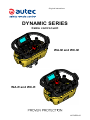
Original instructions
Dynamic Series
Cable control unit
WA-M and WC-M
WA-R and WC-R
LICCUE00-00
Warnings and caption for the documentation attached to the cable control unit
This manual is an integral part of the cable control unit and aims at providing all information
for its usage and maintenance.Always remember that:
-- photos and drawings are useful examples that help understand the instructions and
warnings of each cable control unit configuration
-- if necessary, contact Autec if any of the instructions and/or warnings are not clear.
No part of the documentation may be reproduced, in any form or by any means, without
written permission of Autec (including recording and photocopying).
If documentation is lost or damaged, ask Autec for a copy. Please specify the serial number
of the cable control unit.
This manual must be kept for the whole life of the cable control unit: after reading it, keep it
on file for future reference.
Information contained in the documentation related to the cable control unit adds to and
completes the information provided by the manufacturer of the cable controlled machine
and/or by those who install the cable control unit on the machine.
All installation, usage and maintenance operations must be carried out by qualified technicians
who are suitably trained with respect to the relevant norms and laws.
Therefore, this manual must be read and understood in all its parts by the user and by:
-- the owner and/or installer of the cable control unit
-- the person responsible for and in charge of maintenance and/or safety in the workplace
where the cable control unit is used.
As for instructions and warnings regarding the machine where the cable control unit is installed,
follow the instructions provided by the manufacturer in the machine's manual.
Three symbols are employed in the user manual, which are used to highlight specific safetyrelated issues. They are classified according to the hazardous situation that may arise and
on the possible consequences:
Symbol
If the highlighted instructions are not respected ...
... a dangerous situation
will occur…
...consequences for
people may be…
...consequences for
property may be…
…highly probable.
… critical (death or
physical damage).
… critical.
… probable.
… critical (death or
physical damage).
… critical.
… probable.
… moderate (non-severe
physical damage).
… moderate.
This symbol is also used, and it identifies texts to be read carefully.
AUTEC
LICCUE00-00
Index
1
Description of the cable control unit .................................................................... 6
1.1 Units WC-M and WC-R ..................................................................................... 9
1.2 Units WA-M and WA-R ..................................................................................... 9
2
Conformity .............................................................................................................. 9
3
Technical data ...................................................................................................... 10
3.1 WA-R and WA-M ............................................................................................ 10
3.2 WC-R and WC-M ............................................................................................ 10
4
Technical data sheet ............................................................................................ 10
5Plates .................................................................................................................... 11
6Applications ......................................................................................................... 11
7
Classification of commands ................................................................................ 12
7.1 Command type: analogue, digital or direction command ................................. 12
7.2 Name of commands ........................................................................................ 12
8
Mushroom pushbutton ........................................................................................ 12
8.1 Stop function ................................................................................................... 12
8.2 Emergency stop .............................................................................................. 12
9Risk assessment .................................................................................................. 13
9.1 Risk assessment for machines controlled by the unit ...................................... 13
9.2 Staff training ................................................................................................... 14
9.3 Working conditions ......................................................................................... 14
10 Warnings for use .................................................................................................. 15
10.1Before starting to work .................................................................................... 15
10.2During normal operation ................................................................................. 16
10.3After using the unit .......................................................................................... 17
11 Unit's life cycle ..................................................................................................... 17
11.1Transportation and storage ............................................................................. 17
11.2Installation ...................................................................................................... 18
11.3Use ................................................................................................................. 18
11.4Maintenance of the unit ................................................................................... 19
11.5Machine maintenance ..................................................................................... 23
11.6Disposal .......................................................................................................... 23
12 Light signals ......................................................................................................... 24
13 General operating instructions ........................................................................... 25
13.1Unit's power on ............................................................................................... 25
13.2Enabling the unit ............................................................................................. 25
13.3Command activation ....................................................................................... 25
13.4Data Feedback Function ................................................................................. 25
13.5Automatic unit disabling .................................................................................. 26
13.6Switching off the unit ....................................................................................... 26
14 Operation .............................................................................................................. 27
14.1Starting keyswitch ........................................................................................... 27
14.2START pushbutton ......................................................................................... 27
14.3Mushroom pushbutton .................................................................................... 28
14.4Command meaning ......................................................................................... 28
LICCUE00-00
AUTEC
15
16
Values of proportional outputs ...........................................................................
15.1Light signals during the REMOTE SETUP procedure ......................................
15.2Calibrating maximum and minimum values of proportional outputs .................
15.3Calibrating values related to the rest position of proportional outputs (offset) ..
15.4Inverting the direction of the joystick's axis .....................................................
15.5Restoring factory settings ...............................................................................
Troubleshooting ...................................................................................................
16.1Unit with Data Feedback function ....................................................................
16.2Solutions in case of malfunction ......................................................................
AUTEC
32
33
33
34
35
35
35
35
36
LICCUE00-00
6
1
Description of the cable control unit
Description of the cable control unit
The Dynamic series cable control unit (from now on referred to as "unit") is a command and
control system which is electrically connected to a machine and enables its control.
The user controls the machine by acting on the actuators on the unit.
Depending on the application, the unit is available in two different sizes. The bigger units,
WA-M and WC-M, enable the use of more actuators than the two smaller units, WA-R and
WC-R, to meet the needs of complex applications requiring a more functions.
LICCUE00-00
A
Machine
B
Cable
C
Unit
AUTEC - Dynamic Series
Description of the cable control unit
7
WA-M and WC-M
A
Display or LED (if present)
G
Technical data plate
B
LED
H
Identification plate
C
Actuators (joysticks, selectors,
pushbuttons)
J
Plug or cable gland
Mushroom pushbutton
K
Starting keyswitch
D
W-TEACH pushbutton
L
START pushbutton
E
F
Output protection fuse
AUTEC - Dynamic Series
LICCUE00-00
8
Description of the cable control unit
WA-R and WC-R
A
Display or LED (if present)
G
Technical data plate
B
LED
H
Identification plate
C
Actuators (joysticks, selectors,
pushbuttons)
K
Starting keyswitch
Mushroom pushbutton
L
START pushbutton
D
W-TEACH pushbutton
M
Cable gland
E
F
Output protection fuse
LICCUE00-00
AUTEC - Dynamic Series
Conformity
1.1
9
Units WC-M and WC-R
Units WC-M and WC-R interface with the machine through a CAN network (of which they
are slave nodes) and through some digital outputs.
1.2
Units WA-M and WA-R
Units WA-M and WA-R interface with the machine through proportional and digital outputs
and through a CAN network (of which they are slave nodes).
2
Conformity
Units WA-M, WA-R, WC-M and WC-R comply with the EMC Directive (2004/108/EC) and
the LVD Directive (2006/95/EC).
Units WA-M, WA-R, WC-M and WC-R also comply with the standards provided in the EC
Declaration of Conformity that is enclosed with this manual.
AUTEC - Dynamic Series
LICCUE00-00
10
3
Technical data
Technical data
Power supply ......................................................................................................... 8-30V
Protection of power supply (resettable fuse) ................................................................ 1.3A
Rated current of the contacts of the mushroom pushbutton .............................. 3A (30V )
Rated current of SO_1 and SO_2 outputs ......................................................... 2A (30V )
Protection of outputs (fuse F1) ........................................................ 10A (32V , autofuse)
Housing material ........................................................................................... PA6 (20% fg)
Protection degree ........................................................................................ IP65 (NEMA 4)
Dimensions of WA-M and WC-M ................................... 310x210x190mm (12.2x8.3x7.5In)
Dimensions of WA-R and WC-R .................................... 260x200x190mm (10.2x7.9x7.5In)
Weight of WA-M and WC-M ............................................................................ 2.5kg (5.5Lb)
Weight of WA-R and WC-R ............................................................................ 2.0kg (4.4Lb)
Performance Level of safety functions according to EN ISO 13849-1 / EN IEC 62061:
STOP protection ............................................................................. up to PL d cat.3 / SIL 2
3.1
WA-R and WA-M
Number of analogue outputs (PWM) ............................................................................... 12
Number of analogue outputs (voltage) .............................................................................. 6
Number of digital outputs ................................................................................................. 4
Rated current of analogue outputs (PWM) ........................................................ 2A (30V )
Rated current of analogue outputs (voltage) ................................................ 10mA (28V )
Rated current of digital outputs ......................................................................... 2A (30V )
3.2
WC-R and WC-M
Number of digital outputs ................................................................................................. 4
Rated current of digital outputs ......................................................................... 2A (30V )
4
Technical data sheet
The technical data sheet contains the configuration of the unit and shows the relation between
commands sent and the machine's movements and functions. It also contains the wiring
diagram showing the connection between the unit and the machine.
The technical data sheet must be filled in, checked and signed by the installer, who is
responsible for a correct wiring.
The technical data sheet must always be kept toghether with this manual (always keep a
copy of the technical data sheet when it is used for administrative purposes).
The wiring of the unit outputs must always reflect the wiring indicated in
the technical data sheet.
LICCUE00-00
AUTEC - Dynamic Series
Plates
11
5Plates
The unit has the following plates:
Plate
Content
identification plate
Unit's serial number (TU ID), bar code and manufacturing
year.
technical data plate
Name, main technical data and the unit's mark.
A serial number (TU ID) univocally identifies the unit.
The TU ID is on the unit's identification plate.
This is the only reference to be used both for maintenance operations and for declarations
to competent bodies.
Plates on the unit must not be:
-- removed from their position (removal will invalidate the guarantee)
-- altered or damaged (contact Autec for replacement)
6Applications
The unit can be installed on hoisting and material handling machines and on machines
for moving, raising and transporting people (e.g. hydraulic cranes, aerial work platforms,
telehandlers, concrete pumps).
The unit must not be installed:
-- on machines working in zones with risk of explosion
-- on machines where the unit's power supply does not come from a battery
or from a power supply unit with safety isolating transformer
-- on machines that control loads that are not isolated from AC power
supply (if that is the case)
-- on machines for which a risk assessment (see chapter 9) is not possible
or gave negative results.
Autec cannot be held responsible if the unit is installed on forbidden applications.
AUTEC - Dynamic Series
LICCUE00-00
12
Classification of commands
7
Classification of commands
7.1
Command type: analogue, digital or direction command
Commands activated by the unit are classified according to their type: they can be either
analogue or digital commands.
Analogue commands generate proportional outputs as a function of the position of the
corresponding actuator.
Digital commands switch the status of their corresponding output, according to the position
of the related actuator. This status can either be on or off.
Direction commands are digital commands paired with analogue commands, and are used
to specify the movement direction.
7.2
Name of commands
All commands activated by the unit are identified by abbreviations, which are provided in
the technical data sheet to show the relation between the activated commands and the
machine's functions.
The names of the unit outputs are not the names of commands. Check the technical data
sheet to know which name they were given.
8
Mushroom pushbutton
The unit has a mushroom pushbutton that complies with standard IEC 60947-5-5 (see
paragraph 14.3).
Such pushbutton can perform the stop function or act as an emergency stop.
The machine manufacturer or those who install the unit on the machine determine whether
the mushroom pushbutton performs the stop function or the emergency stop.
8.1
Stop function
When the mushroom pushbutton is used to perform the machine's stop, it is marked with
the “STOP” lettering.
The stop function brings the machine to a safe state every time it is necessary to stop it due
to a potentially hazardous situation. This function is deliberately activated by the user by
pressing this pushbutton.
8.2
Emergency stop
When the mushroom pushbutton is used as an emergency stop device, it is red on a yellow
background, and it is marked with the “E-STOP” or “EMERGENCY STOP” lettering.
The emergency stop device complies with standard ISO 13850 and it must be included in an
emergency stop circuit that complies with the same standard.
Emergency stops must meet the requirements provided in the Machinery Directive 2006/42/EC.
LICCUE00-00
AUTEC - Dynamic Series
Risk assessment
13
9Risk assessment
As required by standards ISO 12100 and ISO 14121, all machines must undergo risk
assessment and related analysis.
The unit can only be installed and used if this assessment gives positive results.
The machine manufacturer and/or the person who decides upon the
installation and use of the unit is responsible for this risk assessment.
Autec cannot be held responsible if this assessment has not been carried out correctly
or is incomplete.
If required by the risk assessment, implement protection measures to prevent, reduce and
report potential hazardous situations.
9.1
Risk assessment for machines controlled by the unit
When carrying out risk assessment for the machine or for the system where the unit is
installed, the following must be considered:
-- some machines cannot be controlled by the unit: check for forbidden applications (see
chapter 6)
-- dynamic laying wiring may be subject to crushing, abrasion, traction or shearing
-- the "independent actuators"(see paragraph 14.4.7) may activate the related functions
even when the unit is disabled or not powered
-- all warnings related to installation, use and maintenance provided by Autec must be
taken into account.
Please allow for installation of suitable cable hoses or carriers to enable the operator to
move safely.
Work organisation, machines' position, passages, etc. shall be planned so
as to avoid that the unit's wiring may be involuntarily and unintentionally
damaged by moving trolleys or by the ongoing operations.
AUTEC - Dynamic Series
LICCUE00-00
14
Risk assessment
9.1.1 Protection from unintended activation
The unit housing is manufactured in such a way that it protects the actuators from unintentional
activation, while meeting at the same time the operating needs, the comfort requirements
and law restrictions.
Assessment shall be made to establish possible additional protection measures for the
actuators (i.e. commands requiring two-hand operation, “dead-man” function) if particular
environments, equipment and working modes could cause accidental bumps to the actuators.
9.1.2 Command activation and loss of command
Please consider that it is possible to unintentionally activate a command and/or involuntarily
lose the selection of a command. Such anomalous events may be caused by electro-mechanical
or mechanical damages in the system "machine+unit".
Carefully evaluate the possible consequences of such malfunction.
If required by the risk assessment, implement protection measures to prevent, reduce and
report potential hazardous situations.
9.2
Staff training
All installation, usage and maintenance operations must be carried out by qualified technicians
who are suitably trained with respect to:
-- warnings resulting from risk assessment
-- regulations and reference laws
-- instructions and warnings provided in the documents related to the unit and to the machine
-- Independent actuators on the unit
-- instructions provided by those who install the unit on the machine and by the person in
charge for safety in the workplace where the system "machine + unit" is used.
9.3
Working conditions
To guarantee correct use of the unit, all current regulations regarding safety at work and
accident prevention must be respected. All applicable standards and regulations valid in the
user country, regarding the use of both the machine and the unit, must always be respected.
Autec cannot be held responsible if the unit is used in unlawful working conditions.
LICCUE00-00
AUTEC - Dynamic Series
Warnings for use
10
15
Warnings for use
In addition to all instructions provided by the machine manufacturer, by the installer of the
unit and by the person responsible for the safety of the work area, users shall always respect
the following warnings.
10.1 Before starting to work
Stand in a position that allows the direct supervision of the machine and of
the load's movements, and stay in a place that preserves the user's safety
conditions in respect of other operations and/or activities and/or processes
carried out in the workplace.
Always check the correct mechanical operation of the mushroom pushbutton.
If it is impossible or difficult to press this pushbutton, do not use the unit.
The use of the unit entails risk of electric shock when working near overhead
or underground power line's cables.
If the unit is connected with the machine through dynamic laying wiring, do
not pull the cables to pick up the unit..
Never enable or use the unit if the working conditions present the risk of
losing balance or tripping.
Only enable or operate the unit when starting work: improper use may cause
hazardous situations.
Get familiar with the relation between the actuators and the machine's
movements (this is indicated in the attached technical data sheet) and
learn symbols on the unit's panel (symbols are defined by the machine
manufacturer and/or installer depending on the machine's operation and
functions).
AUTEC - Dynamic Series
LICCUE00-00
16
Warnings for use
10.2 During normal operation
Pay attention to the entire work area. Immediately press the mushroom
pushbutton when a hazardous situation occurs.
Directly watch and check all machine's and load's movements.
Be particularly careful when releasing the joysticks: do not release them
too quickly and do not disable or switch off the unit when a movement is
being performed, because the load and the machine may be subject to
dangerous swings.
If the unit is connected with the machine through dynamic laying wiring, lay
the cables in such a way to prevent them from being crushed or strained
by people or objects. Avoid contact with sharp or cutting objects that can
cut the cables' protective sheath.
Use the unit in a simple and comfortable way, avoiding accidental falls.
The waist belt and the shoulder harness provided with the unit are used
for that purpose.
Pay particular attention to warnings and visual and acoustic signals, and
take all measurements and steps to avoid that movements of the machine
may lead to hazardous situations for people and/or property.
In case of malfunction, disable the system “machine+unit” until the problem
has been completely solved.
LICCUE00-00
AUTEC - Dynamic Series
Unit's life cycle
17
10.3 After using the unit
Switch off the unit when work is stopped or temporarily interrupted. Do not
leave the load hanging.
If possible, disconnect the unit and the wiring and store them in a safe place
(e.g. the vehicle's cab).
Never leave the unit unguarded when the starting keyswitch is inserted.
11
Unit's life cycle
To ensure safe and long-lasting operation of the unit, carefully follow the instructions provided
for each stage of the product life cycle.
11.1 Transportation and storage
The unit must always be transported and stored inside its packing until it is
installed on the machine.
Environmental transportation and storage conditions are given in the following table.
Temperature
Relative Humidity
Air Pressure
Transportation
Class 2K4
-40°C to +70°C
(-40°F to +158°F)
Class 2K4
95% at 45°C (113°F)
Class 2K4
70kPa to 106kPa
Storage
Class 1K5
-40°C to +85°C
(-40°F to +185°F)
Class 1K3
5% to 95%
Class 1K5
70kPa to 106kPa
AUTEC - Dynamic Series
LICCUE00-00
18
Unit's life cycle
11.2 Installation
Always follow the instructions provided in the technical data sheet to carry
out correct installation.
Please contact the machine manufacturer or the person who decided upon the
installation of the unit for instructions and warnings regarding installation.
The unit can only be installed and tested by competent staff that masters the
technical knowledge required to carry out these procedures and is qualified
according to the regulation of the country where the unit is mounted.
Only if the unit is installed correctly can it be used safely.
11.3 Use
The unit must be used only by skilled and properly trained personnel.
When the unit is installed on board vehicles, switch off the unit while the
vehicle is moving.
All warnings for correct use are given in chapter 10.
All instructions for correct use are given in chapters 13 and 14.
Environmental working conditions are given in the following table.
Use
LICCUE00-00
Temperature
Relative Humidity
Air Pressure
Class 5K4H
-25°C to +55°C
(-13°F to +131°F)
Class 5K2
5% to 95%
Class 5K2
70kPa to 106kPa
AUTEC - Dynamic Series
Unit's life cycle
19
11.4 Maintenance of the unit
The following instructions provide information to safely carry out routine and special
maintenance operations for the unit.
They shall be completed by:
-- instructions provided by the machine manufacturer
-- directions provided by the installer of the unit on the machine
-- regulations regarding safety at work and accident prevention in force in the country
where the unit is used.
All fine-tuning, checking and maintenance actions carried out on the unit shall be verified and
recorded by the person in charge of carrying out maintenance on the machine.
Before any maintenance operation, disconnect power supply from the unit.
If independent actuators are present, disconnect all electrical connections
in the unit.
After each maintenance action, always make sure that all commands sent
by the unit only activate the corresponding expected operations.
In case of malfunction or damaged parts, disable the system “machine+unit”
until the problem has been completely solved.
After each maintenance operation, if the unit has been opened, close it
correctly in order not to endanger its protection degree from dust and water:
check that the gasket is intact, correctly overlay the two parts of the housing
and tighten all the screws using a 70Ncm (6.2lbfin) tightening torque.
AUTEC - Dynamic Series
LICCUE00-00
20
Unit's life cycle
11.4.1 Routine maintenance
Routine maintenance consists of operations needed to preserve the unit's normal usage
conditions, thus implementing fine-tuning, checks, planned replacement actions that necessarily
arise from the normal use of the product.
All given instructions must be followed correctly at each commissioning, that is:
-- whenever the unit and/or the machine is installed or assembled
-- whenever the machine location/position changes
-- after special maintenance.
Routine maintenance carried out as described in this manual is fundamental to safely use
the unit.
Special applications may need more specific routine maintenance actions to be carried out
at different periods (i.e. if the working environment is particularly dirty, in case of heavy
applications or if the system is used very frequently, some maintenance actions may be
required more frequently, depending on the decision of the person in charge for safety in
the work site).
11.4.2 Daily routine maintenance
Before starting to work:
-- make sure that the gaskets, bellows and caps of the joysticks, selectors and pushbuttons
are intact, soft and elastic
-- make sure that the unit's panel symbols can be easily recognised and replace the panel
if necessary
-- check that the two plates on the unit are readable and intact
-- If the unit is connected with the machine through dynamic laying wiring, make sure that
the cables are intact along their whole length.Cables' sheaths must not be damaged,
especially at the cable glands. Make sure that the connecting plugs and sockets are
intact and plugged.
-- check the correct mechanical operation of the mushroom pushbutton.
During normal operation:
-- check structural integrity of the unit
-- make sure that materials that could endanger the unit usage and safety (such as concrete,
sand, lime, dust) do not deposit on it.
After using the unit:
-- clean the unit: never use solvents or flammable/corrosive materials and do not use highpressure water cleaners or steam cleaners
-- if possible, store the unit and its wiring in a clean and dry place, far from heat sources.
LICCUE00-00
AUTEC - Dynamic Series
Unit's life cycle
21
11.4.3 Three-month routine maintenance
Every three months:
-- check that wiring is intact along its whole length.Sheaths of the connecting cables must
not be damaged, especially at the cable glands. Make sure that the connecting plugs
and sockets are intact and plugged.
-- check that when the mushroom pushbutton is activated, the machine is taken to a safe
state and the engine switches off, if expected
-- make sure that the unit does not enable when a movement command is activated (try to
enable the unit after moving the joysticks out of their rest position for each semi-axis).
11.4.4 Special maintenance
Special maintenance consists of repairs needed due to failure, damage, malfunction of the unit,
and they are carried out with the aim of restoring the original usage and working conditions.
Prior to contacting the support service technicians:
-- read and understand all documents related to the unit, and make sure
that all the instructions they contain have been accomplished correctly
-- follow the instructions to detect possible malfunctions and their origins.
Any fault should be repaired by authorised personnel only (contact the
support service of the machine's manufacturer), using original Autec spare
parts only.
For faster and more effective service please report the following data:
-- serial number
-- purchase date (given on the certificate of guarantee)
-- description of the problem found
-- address and telephone number of the place where the device is being used (with the
name of the person to contact)
-- local supplier.
AUTEC - Dynamic Series
LICCUE00-00
22
Unit's life cycle
11.4.5 Preventive replacement of actuators (joysticks, pushbuttons and selectors)
Each actuator on the unit can be used for a defined maximum number of operations.
Replace joysticks, pushbuttons and selectors on the unit before they reach
the maximum number of operations, even though they are still working.
Replacement prevents possible failures that may lead to loss of safety.
Actuator
Max. operations
Actuator
Max. operations
5x10⁶
5x10⁶
5x10⁶
106
3x10⁶
6x10⁶
105
106
105
LICCUE00-00
AUTEC - Dynamic Series
Unit's life cycle
23
11.5 Machine maintenance
Follow instructions provided by the machine manufacturer and by the installer of the unit, in
order to carry out machine maintenance.
When carrying out maintenance on the machine, always disconnect power
supply from the unit.
Disconnect all unit's electrical connections whenever machine maintenance
is carried out (i.e. when soldering).
11.6 Disposal
When disposing of the unit, give it to the waste separate collecting services in the user's country.
AUTEC - Dynamic Series
LICCUE00-00
24
Light signals
12
Light signals
The unit may have two or four LEDs.
A
Red LED
B
Green LED
C
Red LEDs for Data
Feedback function
In both cases, a green LED [B] and a red LED [A] are always available, and they provide
information regarding the unit.
If the unit has 4 LEDs, the side LEDs [C] are red and provide information coming from the
machine (Data Feedback function).
The green LED [B] …
…is off.
The unit is not powered.
… blinks fast
The unit is powered.
… blinks slowly
The unit is enabled.
The red LED [A]…
... is illuminated for 2 secondsa
Meaning
The unit does not work correctly.
... blinks oncea
At enabling, the unit detects that the mushroom
pushbutton is activated or damaged.
... blinks twicea
At enabling, the unit detects that one of the commands
D2-D20 or SAFETY is activated or damaged (see
technical data sheet).
... blinks four timesa
At enabling, the unit detects that one of the commands
A1-A8, L1-L8 and H1-H8 is activated or damaged (see
technical data sheet).
... is steady on.
a.
Meaning
The REMOTE SETUP procedure is being performed (see
chapter 15.).
An acoustic signal is also heard when the red LED [A] is illuminated.After this signal, the unit is
disabled.
LICCUE00-00
AUTEC - Dynamic Series
General operating instructions
13
25
General operating instructions
13.1 Unit's power on
To power on the unit, do the following:
1. power the unit respecting the voltage limits provided in the technical data.
2. insert the starting keyswitch in the unit and turn it (see paragraph 14.1.1).
13.2 Enabling the unit
To enable the unit to send commands to the machine, press the START pushbutton when
the unit is powered on, and do not release it until the green LED [B] starts blinking slowly.
13.3 Command activation
When the unit is enabled it is possible to move the joysticks, pushbuttons and switches
corresponding to the command you want to perform.
The user must be properly trained about the symbols on the unit's panel, to be aware of the
relation between actuators and movements on the machine (symbols used are defined by
the machine manufacturer according to the functions of the machine).
Some specific commands may be present on the unit (see paragraph 14.4).
13.4 Data Feedback Function
The user receives information and/or signals concerning the controlled machine by means
of the Data Feedback function.
During normal operation of the unit, pay particular attention to the indications displayed
and signalled by the display or by the LEDs: they can be helpful to evaluate the machine
working status.
Any information shown and signalled on the display or through the LEDs
can never be considered or used as a safety signal or for legal metrology.
When operating and moving the machine, remember that the unit does not
intervene autonomously when potential hazardous situations are displayed
and signalled.
AUTEC - Dynamic Series
LICCUE00-00
26
General operating instructions
13.4.1 Operation with display
If the unit has a display, it is possible to show signal icons, measurements collected from
the machine and their description.
The machine manufacturer chooses which information are displayed and the way they are
displayed (icons and/or measurements and/or descriptions).
13.4.2 Operation with LED
If the unit has an LED array, specific machine conditions are signalled through their illumination
(i.e. load limits, limit switch, …).
The signalled conditions depend on the settings chosen by the machine manufacturer.
13.5 Automatic unit disabling
The unit automatically disables if it remains enabled for a time equal to the “disabling time”
while none of these commands is activated: SAFETY, D2-D10, H1-H8 and L1-L8.
The activation of this function and its cut-in time are decided by the machine manufacturer
(see technical data sheet).
The independent actuators may activate the corresponding functions/
commands even when the unit is disabled
13.6 Switching off the unit
The unit shall be switched off each time work is stopped: remove the starting keyswitch (see
paragraph 14.1.2) and always store it in a safe place.
If possible, also store the unit in a safe place.
When the unit is installed on board vehicles, switch off the unit while the
vehicle is moving.
The independent actuators may activate the corresponding functions/
commands even when the unit is disabled
LICCUE00-00
AUTEC - Dynamic Series
Operation
14
27
Operation
14.1 Starting keyswitch
The unit has a starting keyswitch from which it is powered.
14.1.1 Inserting the starting keyswitch
Do the following to insert the starting keyswitch:
1. push the starting keyswitch into its receptacle
2. turn the starting keyswitch clockwise.
14.1.2 Removing the starting keyswitch
Do the following to remove the starting keyswitch:
3. turn the starting keyswitch anticlockwise
4. pull the starting keyswitch to remove it from its receptacle.
14.2 START pushbutton
The START pushbutton is used to:
-- enable the unit (see paragraph 13.2 and 13.5).
-- activate the horn when the unit is enabled.
AUTEC - Dynamic Series
LICCUE00-00
28
Operation
14.3 Mushroom pushbutton
The mushroom pushbutton should be pressed when it is necessary to
immediately stop the machine when a dangerous condition occurs.
When the mushroom pushbutton is pressed, the machine
stops and the unit is disabled (the green LED [B] blinks fast).
To start working again after the mushroom pushbutton has
been pressed do the following:
1. make sure that the working and usage conditions are safe
2. turn the mushroom pushbutton in the arrow direction
to unlock it
3. enable the unit (see paragraph 13.2).
14.4 Command meaning
Commands on the unit are specified according to the machine's operations and functions.
They are specified by the machine manufacturer, who also chooses the symbols used.
Some of the commands available on the unit are described in the following paragraphs
(symbols provided here are generally used).
14.4.1 RPM+/- switch (during normal operation)
This switch increases (rpm +) or decreases (rpm -) the engine
revolutions of the machine.
Symbol
Meaning
This symbol indicates the increase of the machine's engine revolutions.
This symbol indicates the decrease of the machine's engine revolutions.
LICCUE00-00
AUTEC - Dynamic Series
Operation
29
14.4.2 TEACH switch (during REMOTE SETUP)
This switch is used to calibrate minimum and maximum values
of proportional outputs and to invert the movement direction
of the joystick's axis.
Symbol
Meaning
This symbol identifies the TEACH+ command.
This symbol identifies the TEACH- command.
14.4.3 W-TEACH pushbutton
This pushbutton is used to:
-- enter the REMOTE SETUP procedure.
-- quit the REMOTE SETUP procedure.
-- restore factory settings for the proportional outputs.
Symbol
Meaning
This symbol identifies the W-TEACH pushbutton.
AUTEC - Dynamic Series
LICCUE00-00
30
Operation
14.4.4 MOVEMENT SPEED SELECTOR
This switch is used to modify the movement speed
Depending on the configuration:
-- it sets two or three speed levels
-- it increases and/or decreases speed.
Symbol
Meaning
This symbol indicates the normal machine's speed.
This symbol indicates a reduction in the machine's speed (the reduction is set by
the manufacturer).
This symbol, if present, indicates a further reduction in the machine's speed (the
reduction is set by the manufacturer).
14.4.5 Engine on/off switch
This switch is used to switch on and off the engine of the
machine.
Symbol
Meaning
This symbol indicates that the engine is powered on.
This symbol indicates that the engine is switched off.
LICCUE00-00
AUTEC - Dynamic Series
Operation
31
14.4.6 DISPLAY pushbutton (if the unit has a display)
This pushbutton is used to:
-- activate the display lighting, if it is off
-- cyclically scroll the information on the display in two
different modes:
-- manual: the lines scroll up each time the pushbutton
is pressed
-- automatic: when the DISPLAY pushbutton is pressed
for 3 seconds, the lines scroll automatically. If the
DISPLAY pushbutton is pressed again, it switches
back to manual mode.
It is not possible to scroll the lines if icons only are displayed.
The display lighting stays on for a time set by the machine
manufacturer.
Symbol
Meaning
This symbol identifies the DISPLAY pushbutton.
14.4.7 Independent actuators
The functions related to the independent actuators may remain active even
if the mushroom pushbutton is pressed or the unit is switched off.
Some actuators on the unit may be directly connected with
the machine's control board.
It may be possible to activate functions related to these
actuators, even when the unit is disabled or switched off.
Symbol
Meaning
This symbol identifies independent actuators.
AUTEC - Dynamic Series
LICCUE00-00
32
15
Values of proportional outputs
Values of proportional outputs
Proportional outputs in the WA-M and WA-R unit are factory set: values are given in the
technical data sheet.
When testing the unit, these values must be checked and, if necessary, modified according
to the machine working mode.
The REMOTE SETUP procedure is used to modify:
-- maximum and minimum values of proportional outputs (see paragraph 15.2)
-- rest position values related to the proportional outputs (offset) (see paragraph 15.3)
-- movement direction of the joystick's axis (see paragraph 15.4)
The REMOTE SETUP procedure can only be performed by skilled and
properly trained personnel.
During the REMOTE SETUP procedure, pay particular attention to the machine
behaviour, as it moves as a response to acting on the actuators.
All values modified by performing the REMOTE SETUP are saved in the memory
card on the unit.
The REMOTE SETUP procedure is used to modify one proportional output at a
time. The procedure will not be performed if the actuators corresponding to the
other proportional outputs are not in the rest position.
If necessary, it is possible to restore factory settings at any time (see paragraph 15.5).
LICCUE00-00
AUTEC - Dynamic Series
Values of proportional outputs
33
15.1 Light signals during the REMOTE SETUP procedure
The following table shows possible light signals appearing during the REMOTE SETUP
procedure.
The red LED
[A]...
... is steady on.
The green LED
[B]...
Meaning
... is steady on.
Calibration of maximum and minimum values of
proportional outputs is being performed (see paragraph
15.2).
... repeats the
sequence: three
blinks and a
pause.
Calibration of the values for the proportional outputs'
rest position is being performed (see paragraph 15.3).
... repeats the
sequence: four
blinks and a
pause.
Inversion of movement direction of the joystick's axis is
being performed (see paragraph 15.4)
... blinks fast.
Two or more analogue commands are activated
simultaneously or restoration of factory settings is being
performed (see paragraph 15.5)
15.2 Calibrating maximum and minimum values of proportional outputs
1. Enable the unit.
2. Press the W-TEACH pushbutton and do not release it until the red LED [A] and the green
LED [B] are steady on.
3. Set the desired values as follows:
-- For the maximum value, move the joystick to the full extension of the semi-axis
corresponding to the output you want to calibrate. Maintain this position and act on
the TEACH selector to set the desired value.
-- For the minimum value, move the joystick slightly out of the rest position of the semiaxis corresponding to the output you want to calibrate. Maintain this position and act
on the TEACH selector to set the desired value.
-- Press the mushroom pushbutton to save the calibration.
-- Unlock the mushroom pushbutton, press and release the START pushbutton.
4. Repeat the previous step to calibrate other values.
5. To quit the procedure, press the W-TEACH pushbutton and do not release it until the red
LED [A] switches off and the green LED [B] blinks slowly.
AUTEC - Dynamic Series
LICCUE00-00
34
Values of proportional outputs
If the proportional outputs are activated by actuators other than joysticks (i.e.
potentiometer, switch), calibrate maximum and minimum values according to the
above mentioned procedure.
If a speed selector is present on the unit, minimum and maximum values have to
be calibrated for each of this selector's positions.
15.3 Calibrating values related to the rest position of proportional outputs
(offset)
1. Enable the unit.
2. Press the W-TEACH pushbutton and do not release it until the red LED [A] and the green
LED [B] are steady on.
3. Activate and release the TEACH+ command and press and release the START pushbutton
within one second.
4. Repeat the previous point until the green LED [B] repeats the sequence: three blinks
and a pause.
5. Set the desired values as follows:
-- Move the joystick slightly out of the rest position on the axis corresponding to the output
to calibrate. Maintain this position and act on the TEACH selector to set the desired value.
-- Press the mushroom pushbutton to save the calibration.
-- Unlock the mushroom pushbutton, press and release the START pushbutton.
6. Repeat the previous step to calibrate other values.
7. To quit the procedure, press the W-TEACH pushbutton and do not release it until the red
LED [A] switches off and the green LED [B] blinks slowly.
If the proportional outputs are activated by actuators other than joysticks (i.e.
potentiometer, switch), calibrate values related to the rest position according to
the above mentioned procedure.
LICCUE00-00
AUTEC - Dynamic Series
Troubleshooting
35
15.4 Inverting the direction of the joystick's axis
1. Enable the unit.
2. Press the W-TEACH pushbutton and do not release it until the red LED [A] and the green
LED [B] are steady on.
3. Activate and release the TEACH+ command and press and release the START pushbutton
within one second.
4. Repeat the previous point until the green LED [B] repeats the sequence: four blinks and
a pause.
5. Do the following to invert the movement direction:
-- Move the joystick out of the rest position on the axis to be inverted. Maintain this
position and activate once the TEACH+ command.
-- Press the mushroom pushbutton to save inversion.
-- Unlock the mushroom pushbutton, press and release the START pushbutton.
6. Repeat the previous step to invert other directions.
7. To quit the procedure, press the W-TEACH pushbutton and do not release it until the red
LED [A] switches off and the green LED [B] blinks slowly.
15.5 Restoring factory settings
This procedure is used to restore factory settings for the proportional outputs.
1. Enable the unit.
2. Press the W-TEACH pushbutton and do not release it until the red LED [A] and the green
LED [B] are steady on.
3. Press the W-TEACH pushbutton three times and do not release it at last pressure; the
green LED [B] blinks fast: this indicates that factory settings are being restored.
4. Release the W-TEACH pushbutton when the green LED [B] is steady on again. If the
W-TEACH pushbutton is released before the green LED [B] is steady on, factory settings
of proportional outputs will not be restored.
5. To quit the procedure, press the W-TEACH pushbutton and do not release it until the red
LED [A] switches off and the green LED [B] blinks slowly.
16
Troubleshooting
When the unit does not work, check if the problem lies with the unit itself or with the machine.
Therefore, before any inspection, try to control the machine with a different control unit, if
applicable. If the problem persists, it lies with the machine. If not, the problem may lie with
the unit. In such case, please refer to paragraph 16.2.
16.1 Unit with Data Feedback function
It is still possible that the unit controls the machine even if the Data Feedback function does
not work properly, or if there is no information and/or signals coming from it.
Contact the support service of the machine manufacturer when the display
or the LEDs do not work properly.
AUTEC - Dynamic Series
LICCUE00-00
36
Troubleshooting
16.2 Solutions in case of malfunction
First make sure that the wiring is intact and correctly connected with both the machine and
the unit and replace it if needed.
Use the light signals on the unit to identify the malfunction and look it up in the following table.
If the problem persists after the suggested solution has been carried out, contact the support
service of the machine manufacturer.
Signals
Possible reason
Solutions
The green LED [B]
is off
The unit is not powered.
Disconnect the power supply and
restore it after 5 minutes: the
restorable thermal fuse may have
temporarily cut in.
The red LED [A] is
steady on and the
green LED [B] blinks
twice.
Error on the memory card.
Contact the support service of the
machine manufacturer.
The red LED [A] is
steady on and the
green LED [B] blinks
fast.
Two or more analogue
commands are being activated
simultaneously within the
REMOTE SETUP procedure.
Check actuators on the unit and
activate one single analogue
command.
The red LED [A]
illuminates steadily for
2 seconds and then the
unit is disabled b.
The unit does not work
correctly.
Contact the support service of the
machine manufacturer.
The red LED [A] blinks
once during the unit's
enabling b.
The mushroom pushbutton is
locked or damaged.
Unlock the mushroom pushbutton.
If this signal persists, contact the
support service of the machine
manufacturer.
The red LED [A] blinks
twice during the unit's
enabling b.
At least one of the actuators
corresponding to commands
D2-D20 and SAFETY is
activated or damaged.
Make sure that the actuators
are in the rest position. If this
signal persists, contact the
support service of the machine
manufacturer.
The red LED [A] blinks
four times during the
unit's enabling b.
At least one of the actuators
corresponding to commands
A1-A8, L1-L8, H1-H8 and
SAFETY is activated or
damaged.
Make sure that the actuators
are in the rest position. If this
signal persists, contact the
support service of the machine
manufacturer.
b.
An acoustic signal is also heard when the red LED [A] is illuminated.After this signal, the unit is
disabled.
LICCUE00-00
AUTEC - Dynamic Series
AUTEC
LICCUE00-00
LICCUE00-00
AUTEC
AUTEC
LICCUE00-00
AUTEC SRL via pomaroli 65 Caldogno (VI) Italy - phone: +39 0444 901000 - mail: [email protected] - www.autecsafety.com