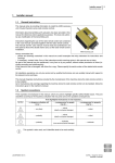
1
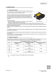
Dynamic series
user manual
Description, warnings and instructions
Conformity and frequencies (915 MHz)
Original instructions
The attached documentation is an integral part of the radio remote control and it aims at providing the instructions needed for using and maintaining the system, with an eye on its safety functions. Always remember that:
- photos and drawings are useful examples that help understand the instructions and warnings
of each radio remote control configuration
- if necessary, contact Autec if any of the instructions and/or warnings are not clear
No part of the documentation may be reproduced, in any form or by any means, without written
permission of Autec (including recording and photocopying).
If documentation is lost or damaged, ask Autec for a copy. Please specify the serial number of
the related radio remote control.
The documentation must be kept for the whole life of the radio remote control: after reading it,
keep it on hand for future reference.
Information contained in the documentation adds to and completes the information provided by
the manufacturer of the remote controlled and/or by those who install the radio remote control
on the machine.
All installation, usage and maintenance operations must be carried out by qualified technicians
who are suitably trained with respect to the relevant norms and laws.
Therefore, this documentation must be read and understood in all its parts by the user and by:
- the radio remote control owner and/or installer
- the person responsible for and in charge of maintenance and/or safety in the workplace
where the radio remote control is used.
As for instructions and warnings regarding the machine where the radio remote control is
installed, follow the instructions given in the machine's manual.
Three symbols are employed throughout documentation, which are used to highlight specific
safety-related issues. They are classified according to the hazardous situation that may arise
and on the possible consequences:
If the highlighted instructions are not respected this…
Symbol
... leads to a
dangerous situation …
... may lead to consequences for people …
... may lead to consequences for
property …
…highly probable.
… critical (death or
physical damage).
… critical.
… probable.
… critical (death or
physical damage).
… critical.
… probable.
… moderate (nonsevere physical damage).
… moderate.
This symbol is also used, and it identifies texts to be read carefully.
INDEX
Part A: Description, warnings and instructions
1 Dynamic Series description ............................................................................... A - 1
1.1 Technical data ................................................................................................. A - 1
1.2 Applications ..................................................................................................... A - 2
1.3 Radio link ........................................................................................................ A - 2
1.4 Classification of commands ............................................................................ A - 2
1.5 Safety functions .............................................................................................. A - 3
1.6 Identifying the radio remote control ................................................................. A - 4
2 Risk assessment ................................................................................................. A - 5
2.1 Risk assessment for radio remote controlled machines ................................. A - 5
2.2 Working conditions .......................................................................................... A - 6
3 Warnings .............................................................................................................. A - 7
3.1 Before starting to work .................................................................................... A - 7
3.2 During normal operation ................................................................................. A - 7
3.3 After using the radio remote control ................................................................ A - 8
4 Radio remote control lifecycle ........................................................................... A - 9
4.1 Transportation and storage ............................................................................. A - 9
4.2 Installation ....................................................................................................... A - 9
4.3 Use .................................................................................................................. A - 9
4.4 Radio remote control maintenance ............................................................... A - 10
4.5 Machine maintenance ................................................................................... A - 14
4.6 Disposal ........................................................................................................ A - 14
5 General operating instructions ........................................................................ A - 15
5.1 Starting up the radio remote control .............................................................. A - 15
5.2 Command activation ..................................................................................... A - 15
5.3 Data Feedback Function ............................................................................... A - 15
5.4 Radio link interruption ................................................................................... A - 16
5.5 Transmitting unit automatic switch off ........................................................... A - 16
5.6 Switching off the transmitting unit ................................................................. A - 17
5.7 Switching off the receiving unit ..................................................................... A - 17
6 Working .............................................................................................................. A - 18
6.1 BATTERY ..................................................................................................... A - 18
6.2 S-KEY ........................................................................................................... A - 18
6.3 START pushbutton ....................................................................................... A - 19
6.4 STOP ............................................................................................................ A - 19
6.5 Command meaning ....................................................................................... A - 19
6.6 Low Power function ....................................................................................... A - 21
6.7 Cable control ................................................................................................. A - 21
7 Troubleshooting ................................................................................................ A - 23
7.1 Radio remote controls with Data Feedback function .................................... A - 23
7.2 Radio remote controls with wire control ........................................................ A - 23
AUTEC
ENG
7.3 Solutions in case of malfunction ................................................................... A - 23
Part B: Conformity and frequencies
1 Conformity ........................................................................................................... B - 1
2 Frequencies ......................................................................................................... B - 1
2.1 Dynamic mode ................................................................................................ B - 2
2.2 Static mode ..................................................................................................... B - 2
3 Market ................................................................................................................... B - 2
Original instructions
Dynamic Series description
A-1
DYNAMIC SERIES
Part A: Description, warnings and instructions
1 Dynamic Series description
Autec Dynamic series industrial
radio remote controls are used to
control machines from a distance, without physical connections (i.e. wires or connecting
cables) between the user and the
machine.
Each of these industrial radio remote controls consists of a portable transmitting unit, from which
the user can remotely control the
machine, and a receiving unit installed on board the machine itself.
1.1 Technical data
Command response time ................................................................................. 80 - 130 ms
Active stop cut-in time (typical) ............................................................................. < 130 ms
Active stop cut-in time (maximum)........................................................................... 200 ms
Passive stop cut-in time1 ............................................................................... 0.5 / 1.2 / 2 s
Hamming distance ........................................................................................................ ≥ 15
Probability of undetected error.................................................................................. < 10-15
Typical working range ................................................................................... 100 m (330 ft)
Working range with Low Power function.......................................................... 30 m (100 ft)
Performance Level of safety functions according to EN ISO 13849-1 / EN IEC 62061:
STOP protection ....................................................................... PL e / SIL 3 (4-wire wiring)
STOP protection ....................................................................... PL d / SIL 2 (2-wire wiring)
Protection against unintended movements from the standstill position (UMFS) .................
........................................................................................................................... PL d / SIL 2
1. Passive stop cut-in time is set by the machine manufacturer (see technical data sheet)
AUTEC
LIDYNE00-02.fm
Dynamic Series
Part A: Description, warnings and instructions
ENG
A-2
Dynamic Series description
1.2 Applications
In compliance with the risk assessment (see chapter 2), this radio remote control
can be installed on hoisting and material handling machines and on machines for
moving, raising and transporting people (i.e. hydraulic cranes, aerial work platforms, telehandlers, concrete pumps).
This radio remote control cannot be installed:
- on machines installed in places where equipment with explosion-proof
characteristics is required
- on machines where the receiving unit power supply does not come from
a battery or from a power supply unit with safety isolating transformer
- to control loads that are not isolated from AC power supply (if that is the
case)
- on machines that may generate dangerous situations if they stop due to
the loss of radio link
- on machines for which a risk assessment (see chapter 2) is not possible
or gave negative results.
Autec cannot be held responsible if the radio remote control is installed on forbidden applications.
1.3 Radio link
The two units constantly communicate with one another through a radio link. This
is an essential requirement to ensure safety for the radio remote controlled machine.
Messages from the units are coded through an address stored in the S-KEY (see
paragraph 6.2). This address is unique (Autec produces it only once), univocal
(specific for each radio remote control) and not reproducible. Each unit can only
decode the messages coming from the unit with the same address. This prevents
messages from other radio equipment from activating any system function.
The units send coded messages to one another:
- messages sent by the transmitting unit contain operational commands to be
carried out by the machine
- messages sent by the receiving unit contain information useful for the automatic management of the working frequency and information about measurements collected from the machine (Data Feedback function).
1.4 Classification of commands
Commands sent by the transmitting unit are classified according to their type.
Dynamic Series
Part A: Description, warnings and instructions
Dynamic Series description
A-3
1.4.1 Command type: analogue, digital or direction command
Commands sent by the transmitting unit can either be analogue or digital.
Analogue commands generate proportional outputs as a function of the position
of the corresponding actuator.
Digital commands switch the status of their corresponding output, according to
the position of the related actuator. This status can either be on or off.
Direction commands are digital commands paired with analogue commands, and
are used to specify the movement direction.
1.4.2 Name of commands
All commands sent by the transmitting unit are identified by abbreviations, which
are also written in the technical data sheet to highlight the match between commands sent and machine functions.
The names of outputs in the receiving unit are not the names of commands.
Check the technical data sheet to know which name they were given.
1.5 Safety functions
Autec radio remote controls are equipped with some functions that provide high
safety levels, in order to safeguard the safety of people and property.
1.5.1 Stop function
The stop function brings the machine to a safe state every time it is necessary to
stop it due to a potentially hazardous situation. This function is either voluntarily
enabled by the user (active stop), as appropriate, or it cuts in automatically and
autonomously (passive stop).
Active stop
Active stop is a function enabled by the STOP pushbutton (see paragraph 6.4).
The transmitting unit sends to the receiving unit a command that immediately
stops the machine. When the STOP pushbutton is pressed, the machine stops in
shorter time than when passive stop cuts in.
Passive stop
Passive stop is a function that cuts in when a fault occurs during operation. When
the radio link is incorrect or interrupted, the receiving unit autonomously stops the
radio remote control. The cut-in time of this function (passive stop cut-in time) is
set by the machine manufacturer (see technical data sheet).
1.5.2 Protection against unintended movements from the standstill position (UMFS)
This safety function protects the system “machine+radio remote control” from unintended movements, namely machine movements not activated intentionally by
AUTEC
LIDYNE00-02.fm
Dynamic Series
Part A: Description, warnings and instructions
ENG
A-4
Dynamic Series description
the user, but resulting from possible electrical and mechanical failure of the radio
remote control.
Such safety function checks the neutral (rest) position of the actuators that control
the machine's movements. Each time one of those actuators is operated, the
transmitting unit sends both the movement command and the “SAFETY” command. Depending on the specific application, outputs related to these commands
are wired in series; alternatively the SAFETY command's outputs drive the safety
device provided on the machine.
1.6 Identifying the radio remote control
The serial number (S/N) is the only reference to be used to uniquely identify the
radio remote control, both if maintenance is needed and when providing statements to competent bodies.
The serial number (S/N) and other information regarding the radio remote control
are provided in some plates both on the transmitting and on the receiving unit.
These plates must not be:
- removed from their position (removal will invalidate the guarantee)
- altered or damaged (contact Autec for replacement).
Dynamic Series
Part A: Description, warnings and instructions
Risk assessment
A-5
2 Risk assessment
As required standards ISO 12100 and ISO 14121, all machines must undergo
risk assessment. It is therefore necessary to evaluate, within the limits of this assessment, if the machine can be radio remote controlled.
The radio remote control can only be used if this assessment gives positive results.
2.1 Risk assessment for radio remote controlled machines
All warnings listed in this manual must also be taken into account during risk assessment and when setting out protection measures for the controlled machine.
When carrying out risk assessment for the machine or for the system where the
radio remote control is installed, the following must be considered:
- some machines cannot be radio remote controlled by Dynamic series radio remote controls (see paragraph 1.1)
- the radio link between the two units may be interrupted due to persistent disturbance or interference.
Whenever the radio link is interrupted (i.e. due to active stop, passive stop, low
battery, automatic switch off, receiving unit not powered):
- all outputs in the receiving unit are disabled (if this generates a hazardous situation, it is necessary that the corresponding commands on the machine are
kept active)
- it is not possible to enable or disable the machine commands until the radio
remote control is started up again.
Due to the characteristics of radio propagation (i.e.: EM interference, near out-ofrange condition), a delay up to the "Passive stop time" (see paragraph 1.1) may
occasionally occur from the moment a command in the transmitting unit is released to the moment its corresponding output in the receiving unit is deactivated.
Those who decide upon the installation of the radio remote control must make
sure that this delay never leads to a dangerous situation in the specific uses.
The transmitting unit housing is manufactured so that it protects the actuators
from unintentional activation, while meeting at the same time the operating
needs, the comfort requirements and law limits.
Assessment shall be made to establish possible additional protection measures
for the actuators (i.e. commands requiring two-hand operation, “dead-man” function) if particular environments, equipment and working modes could cause accidental bumps to the actuators.
AUTEC
LIDYNE00-02.fm
Dynamic Series
Part A: Description, warnings and instructions
ENG
A-6
Risk assessment
The machine manufacturer and/or the person who decides upon radio remote
control use and installation is responsible for this risk assessment.
Autec cannot be held responsible if this assessment is not carried out correctly.
If required by the risk assessment, draw up protection measures to prevent, reduce and report potential hazard situations.
2.2 Working conditions
To guarantee correct radio remote control operation, all current regulations regarding safety at work and accident prevention should be respected. All applicable standards and regulations valid in the user country regarding the use of both
the machine and the radio remote control must always be respected.
Autec cannot be held responsible if the radio remote control is used in unlawful
working conditions.
Dynamic Series
Part A: Description, warnings and instructions
Warnings
A-7
3 Warnings
In addition to all instructions provided by the machine manufacturer, by the installer of the radio remote control and by the person responsible for the safety of the
work area, users shall always respect the following warnings.
3.1 Before starting to work
The transmitting unit shall be used in a simple and comfortable way, avoiding accidental falls. The harness provided with the radio remote control
serves as such.
Stand in a position that allows the direct supervision of the remote controlled machine and its load, and stay in a place ensuring safety conditions in
respect of other operations and/or activities and/or processes that are carried out in the working environment.
Never start up or use the transmitting unit if the working conditions present
the risk of losing balance or tripping.
Always check that the mechanical operation of the STOP pushbutton is correct. If it is impossible or difficult to press this pushbutton, do not use the
radio remote control.
Only start up the transmitting unit when starting work: improper use may
cause hazardous situations.
Never start up or use the transmitting unit in closed spaces, with the machine not in sight, or outside the radio remote control typical working
range: in such cases it is in fact still possible to build a radio link, thus
causing the risk that unwanted commands be carried out by the machine.
3.2 During normal operation
Visually and directly follow all movements of the machine and its load and
remain inside the radio remote control working range.
Pay particular attention to warnings and visual and acoustic signals, and
take all measurements and steps to avoid that movements of the remote
controlled machine may lead to hazardous situations for people and/or
property.
Pay attention to the entire work area. Immediately press the STOP pushbutton when a hazardous situation occurs.
AUTEC
LIDYNE00-02.fm
Dynamic Series
Part A: Description, warnings and instructions
ENG
A-8
Warnings
Do not touch the receiving unit’s metal parts as they may reach high, potentially dangerous temperatures.
In case of malfunction, disable the system “machine+radio remote control”
until the problem has been completely solved.
3.3 After using the radio remote control
Switch off the transmitting unit when work is stopped or temporarily interrupted. Do not leave the load hanging (even when changing the battery).
Never leave the transmitting unit unguarded when the S-KEY is inserted.
Always store the S-KEY in a safe place each time it is removed from the
transmitting unit. If this key is lost, the radio remote control cannot work,
since the transmitting unit needs the address stored in the key to work with
its receiving unit.
Dynamic Series
Part A: Description, warnings and instructions
Radio remote control lifecycle
A-9
4 Radio remote control lifecycle
To ensure a safe and long-lasting operation of Dynamic series industrial radio remote controls, carefully follow the instructions provided for each stage of the
product lifecycle.
4.1 Transportation and storage
Radio remote controls must always be transported and stored inside their original
packing until they are installed on the machine.
Environmental transportation and storage conditions are given in the following table.
Temperature
Relative Humidity
Air Pressure
Transportation
Class 2K3
-40°C to +70°C
(-40°F to +158°F)
Class 2K3
95%
Class 2K3
70 kPa to 106 kPa
Storage
Class 1K5
-40°C to +80°C
(-40°F to +176°F)
Class 1K3
5% to 95%
Class 1K5
70 kPa to 106 kPa
4.2 Installation
The radio remote control can only be installed and tested by competent staff that
masters the technical knowledge required to carry out these procedures and is
qualified according to the regulation of the country where the radio remote control
is mounted.
Only if the radio remote control is installed correctly can it be used safely.
Always follow the instructions provided in the technical data sheet to carry
out correct installation.
Please contact the machine manufacturer or the person who decided upon
the installation of the radio remote control for instructions and warnings regarding the installation.
4.3 Use
The use of industrial radio remote controls is strictly limited to skilled and properly
trained personnel.
When the radio remote control is installed on mobile machines, switch off
the receiving unit when the vehicle travels.
AUTEC
LIDYNE00-02.fm
Dynamic Series
Part A: Description, warnings and instructions
ENG
A - 10
Radio remote control lifecycle
All warnings for a correct use are given in chapter 3.
All instructions for a correct use are given in chapters 5 and 6.
Environmental working conditions are given in the following table.
Temperature
Transmitting unit
Receiving
unit
Class 5K4H
-25°C to +55°C
(-13°F to +130°F)
Class 5K2
Relative Humidity
Air Pressure
Class 5K2
5% to 95%
Class 5K2
70 kPa to 106 kPa
-25°C to +70°Ca
(-13°F to +158°F)
a. The receiving unit can work at 70°C (185°F) only if the sum of currents corresponding to the loads simultaneously activated by digital and analogue outputs does not exceed 10 A.
4.4 Radio remote control maintenance
The following instructions provide information to safely carry out routine and special maintenance operations for the radio remote control.
They shall be completed by:
- instructions provided by the machine manufacturer
- directions provided by the installer of the radio remote control on the machine
- regulations regarding safety at work and accident prevention in force in the
country where the radio remote control is used.
All fine-tuning, checking and maintenance actions carried out on the radio remote
control shall be verified and recorded by the person in charge of carrying out
maintenance on the machine.
In case of failure, emergencies or damaged parts, disable the system “radio
remote control+machine” until the problem has been completely solved.
Before any maintenance operation:
- remove the battery from the transmitting unit
- disconnect power from the receiving unit.
After any maintenance operation:
- always make sure that commands sent by the transmitting unit only activate the corresponding expected operations
- if a unit has been opened, close it correctly, in order not to endanger its
protection degree from dust and water: check that the gasket is intact,
correctly overlay the two parts of the housing and tighten the screws.
Dynamic Series
Part A: Description, warnings and instructions
Radio remote control lifecycle
A - 11
4.4.1 Routine maintenance
Routine maintenance consists of operations needed to preserve the radio remote
control normal usage conditions, thus implementing fine-tuning, checks, planned
replacement actions that necessarily arise from the normal use of the product.
All given instructions must be followed correctly at each commissioning, that is:
- whenever the radio remote control and/or the machine is installed or assembled
- whenever the machine location/position changes
- after special maintenance.
Routine maintenance carried out as described in this manual is fundamental for
using the radio remote control safely.
Special applications may need more specific routine maintenance actions to be
carried out at different periods (i.e. if the working environment is particularly dirt,
in case of heavy applications or if the system is used very frequently, some maintenance actions may be required more frequently, depending on the decision of
the person in charge for safety in the worksite).
4.4.2 Daily routine maintenance
Before starting to work:
- make sure that the battery housing and the battery contacts are always clean
- make sure that the gaskets, bellows and caps of the actuators (joysticks, selectors and pushbuttons) are intact, soft and elastic
- make sure that the transmitting unit panel symbols can be easily recognised
and replace the panel if necessary
- check that the three plates on the transmitting unit are readable and intact
- make sure that the mechanical operation of the STOP pushbutton is correct.
During normal operation:
- check structural integrity of the transmitting unit
- make sure that materials that could endanger the transmitting unit usage and
safety (such as concrete, sand, lime, dust) do not deposit on it.
After using the radio remote control:
- clean the transmitting unit: never use solvents or flammable/corrosive materials and do not use high-pressure water cleaners or steam cleaners
- store the transmitting unit in clean and dry areas.
AUTEC
LIDYNE00-02.fm
Dynamic Series
Part A: Description, warnings and instructions
ENG
A - 12
Radio remote control lifecycle
4.4.3 Three-month routine maintenance
Every three months:
- remove dust or deposit of material from the receiving unit: never use solvents
or flammable/corrosive materials to clean it, and do not use high-pressure water cleaners or steam cleaners
- check structural integrity of the receiving unit
- make sure that the wiring of the receiving unit is intact and connected
- make sure that the receiving unit panel symbols can be easily recognised and
replace the panel if necessary
- check that the plates on the receiving unit are readable and intact.
4.4.4 Special maintenance
Special maintenance consists of repairs needed due to radio remote control failure, damage or malfunction, carried out with the aim of restoring the original usage and working conditions.
Prior to contacting the support service technicians of the machine's manufacturer:
- read and understand all documents related to the radio remote control, and
make sure that all the instructions they contain have been accomplished correctly
- follow the instructions to detect possible malfunctions and their origins (see
chapter 7).
Any fault should be repaired by authorised personnel only (contact the support service of the machine's manufacturer), using original Autec spare
parts only.
The following radio remote control data must be reported in order to make interventions faster and more reliable:
- radio remote control serial number (S/N) and TU ID (transmitting unit identification number)
- purchase date (given on the certificate of guarantee)
- description of the problem found
- address and telephone number of the place where the device is being used
(with the name of the person to contact)
- local supplier.
Dynamic Series
Part A: Description, warnings and instructions
Radio remote control lifecycle
A - 13
4.4.5 Preventive replacement of actuators (joysticks, pushbuttons and selectors)
Each actuator on the transmitting units can be used for a maximum number of
operations.
Replace joysticks, pushbuttons and selectors on the transmitting unit before they reach the maximum number of operations, even though they are
still working.
Replacement prevents possible failures that may lead to loss of safety.
Actuator
Max.
operations
5x10⁶
Actuator
Max.
operations
joystick: 5x10⁶
bellows: 106
5x10⁶
106
3x10⁶
6x10⁶
5x10⁴
106
105
AUTEC
LIDYNE00-02.fm
Dynamic Series
Part A: Description, warnings and instructions
ENG
A - 14
Radio remote control lifecycle
4.5 Machine maintenance
Follow instructions provided by the machine manufacturer and by the installer of
the radio remote control, in order to carry out machine maintenance.
When carrying out maintenance operations on the machine:
- always remove the S-KEY from the transmitting unit
- disconnect power from the receiving unit
4.6 Disposal
When disposing of a radio remote control, give it to the waste separate collecting
services in the user's country.
Please pay particular attention when disposing of batteries: apply local rules. Do
not throw them away with domestic trash.
Dynamic Series
Part A: Description, warnings and instructions
General operating instructions
A - 15
5 General operating instructions
5.1 Starting up the radio remote control
Starting up the radio remote control consists in building a radio link between the
transmitting and the receiving unit. For this purpose, you need to:
1. power on the receiving unit respecting the voltage limits provided in the technical data. The POWER LED switches on
2. insert a charged battery in the transmitting unit (see paragraph 6.1)
3. insert the S-KEY in the transmitting unit
4. press the START pushbutton in the transmitting unit until the POWER LED in
the receiving unit and the green LED in the transmitting unit start blinking slowly.
5.2 Command activation
With the radio remote control started, act on the joysticks, pushbuttons and
switches corresponding to the command to be performed.
The user must be properly trained about the symbols on the transmitting unit panel, to be aware of the matching between actuators and movements on the machine (symbols used are defined by the machine manufacturer according to the
functions of the machine).
Some specific commands may be present on the transmitting unit: see
paragraph 6.5.
5.3 Data Feedback Function
The user receives information and/or signals concerning the controlled machine
by means of the Data Feedback function.
During normal radio remote control operation, pay particular attention to the indications displayed and signalled by the display or through the LEDs: they can be
helpful to evaluate the machine working status.
Any information shown and signalled on the display or through the LEDs
can never be considered or used as a safety signal or for legal metrology.
When operating and moving the machine, remember that the radio remote
control does not intervene autonomously when potential hazardous situations are displayed and signalled.
AUTEC
LIDYNE00-02.fm
Dynamic Series
Part A: Description, warnings and instructions
ENG
A - 16
General operating instructions
5.3.1 Operation with display
If the transmitting unit has a display, it is possible to visualise signal icons, measurements collected from the machine and their description.
Information displayed and how it is displayed (icons and/or measurements and/
or descriptions) depend on the settings chosen by the machine manufacturer.
In addition, two indicators are always present:
- battery charge level (at the bottom on the left)
- quality of radio link (at the bottom on the right).
5.3.2 Operation with LED
If the transmitting unit has an LED array, particular machine conditions are signalled if they are on (i.e. load limits, limit switch, …).
The signalled conditions depend on the settings chosen by the machine manufacturer.
5.4 Radio link interruption
When the radio link is incorrect or interrupted for a certain period of time, the passive stop function automatically cuts in (see paragraph 1.5.1).
The green LED on the transmitting unit switches from blinking slowly to fast blinking.
The POWER LED on the receiving unit switches from blinking to steady on.
Press the START pushbutton to start the radio remote control.
Please note that when the START pushbutton is pressed to start up the radio remote control after the radio link had been interrupted, commands that
were enabled before the interruption are immediately activated. If this may
lead to a dangerous situation, press and then unlock the STOP pushbutton.
Only then, press the START pushbutton.
5.5 Transmitting unit automatic switch off
The transmitting unit automatically switches off when:
- the battery is flat (see paragraph 5.5.1)
- the radio remote control is not used for a certain time (see paragraph 5.5.2)
- the transmitting unit is powered and never switched off for eight hours nonstop (see paragraph 5.5.3).
The green LED on the transmitting unit switches off.
The POWER LED on the receiving unit switches from blinking to steady on.
Press the START pushbutton to start the radio remote control.
Dynamic Series
Part A: Description, warnings and instructions
General operating instructions
A - 17
5.5.1 Low battery
The transmitting unit indicates if the battery is not sufficiently charged (the red
LED blinks and an acoustic signal sounds).
The transmitting unit automatically switches off after 3.5 minutes from the beginning of the signal.
The battery shall be replaced with a charged one (see paragraph 6.1).
5.5.2 When the transmitting unit is not used
If the transmitting unit remains started for a time equal to the “auto switch-off time”
while none of these commands is enabled: SAFETY, D2-D10, H1-H8 and L1-L8,
then
it automatically switches off.
The activation of this function and its cut-in time are set by the machine manufacturer (see technical data sheet).
5.5.3 Non-stop use
The transmitting unit indicates if it has been used for eight hours non-stop (the
red LED blinks and an acoustic signal sounds).
The transmitting unit automatically switches off after 3.5 minutes from the beginning of the signal.
5.6 Switching off the transmitting unit
The transmitting unit shall be switched off each time work is stopped: remove the
S-KEY (see paragraph 6.2) and always store it in a safe place.
5.7 Switching off the receiving unit
The receiving unit shall be switched off each time the radio remote control is not
used to control the machine. Remove power from the unit to switch it off.
When the radio remote control is installed on mobile machines, switch off
the receiving unit when the vehicle travels.
AUTEC
LIDYNE00-02.fm
Dynamic Series
Part A: Description, warnings and instructions
ENG
A - 18
Working
6 Working
6.1 BATTERY
The Dynamic series' transmitting units can only be powered through Autec rechargeable batteries.
See the battery charger manual enclosed in the packaging with the battery charger for any warnings and instructions regarding the batteries.
Batteries shall be inserted in their housing in the transmitting unit, with the technical data plate facing down and their contacts towards the contacts on the transmitting unit.
2
1
3
4
To insert a battery, proceed as follows:
1. push the battery towards the contacts on the transmitting unit
2. push the battery downwards.
To remove a battery, proceed as follows:
3. push the battery towards the contacts on the transmitting unit
4. lift the battery.
6.2 S-KEY
In the transmitting unit, the radio remote control address
is stored in the S-KEY. For this reason, the radio remote
control cannot work without this key.
The S-KEY can only be used in the transmitting unit
of the radio remote control where it belongs (main
transmitting unit).
Dynamic Series
Part A: Description, warnings and instructions
Working
A - 19
As the radio remote control address is stored in the S-KEY, use it with utmost care to reduce risks that may result from incorrect handling.
If the main transmitting unit cannot be used because it has been lost or
damaged, the back-up transmitting unit can be used instead. In this case,
insert the S-KEY in the back-up unit. The back-up unit is identical to the
main unit; the only difference is the presence of the plate “BACK-UP UNIT”
on the battery housing.
6.3 START pushbutton
The START pushbutton is used to:
- start up the radio remote control (see paragraphs 5.1,
5.4 and 5.5)
- activate the horn when the radio remote control is started.
6.4 STOP
The STOP pushbutton should be pressed when it is necessary to stop the
machine immediately when a dangerous condition should occur.
When the STOP pushbutton is pressed, the machine stops
(active stop: see paragraph 1.5.1), and the transmitting unit
switches off.
To start working again after the STOP pushbutton has been
pressed:
1. make sure that the working and usage conditions are
safe
2. turn the STOP pushbutton in the arrow direction to unlock it
3. start up the radio remote control (see paragraph 5.1).
6.5 Command meaning
Commands on the transmitting unit are established according to the machine's
operations and functions. They are established by the machine manufacturer,
who also chooses the symbols used.
AUTEC
LIDYNE00-02.fm
Dynamic Series
Part A: Description, warnings and instructions
ENG
A - 20
Working
Some of the commands available on the transmitting unit may be those provided
below; in this case, symbols used are generally those given here:
RPM+/- (during normal operation)
This switch increases (rpm +) or decreases (rpm -) the engine
revolutions of the remote controlled machine.
TEACH (during REMOTE SETUP)
This switch is used to calibrate minimum and maximum values
of proportional outputs.
MOVEMENT SPEED SELECTOR
This switch is used to modify the movement speed. According
to the configuration:
- it sets two or three speed levels
- it increases and/or decreases speed.
These three symbols are used:
Symbol
Meaning
This symbol indicates the typical machine's speed.
This symbol indicates a reduction in the machine's speed
(the reduction is set by the manufacturer).
This symbol, if present, indicates a further reduction in
the machine's speed (the reduction is set by the manufacturer).
ENGINE
This switch is used to switch on and off the engine of the remote
controlled machine.
Symbol
Meaning
This symbol indicates that the engine is powered on.
This symbol indicates that the engine is switched off.
Dynamic Series
Part A: Description, warnings and instructions
Working
A - 21
DISPLAY pushbutton (if the transmitting unit has a display)
This pushbutton is used to:
- activate the display lighting, if it is off
- cyclically scroll the information on the display in two different
modes:
- manual: the lines scroll up each time the pushbutton is
pressed
- automatic: when the DISPLAY pushbutton is pressed for
3 seconds, the lines scroll automatically. If the DISPLAY
pushbutton is pressed another time, it switches back to
manual mode.
It is not possible to scroll the lines if icons only are displayed.
The display lighting stays on for a time set by the machine manufacturer.
6.6 Low Power function
The LOW POWER function allows transmission at a lower power than the nominal power (see paragraph 1.1) and reduces the radio remote control working
range.
This function aims at:
- making it easier to work with several systems in the same working environment (i.e.: many working machines in the same working area)
- extending the battery run-time.
This function is established by the machine manufacturer (see technical data
sheet).
6.7 Cable control
The wire control is used:
- in particular working conditions, established by the machine manufacturer
- when it is not possible to build a radio link between the radio remote control
units
- when working in environments where using radio frequencies is not allowed or
is dangerous
- when a fully charged battery is not available.
When using the wire control, it is not possible to eliminate the electric
shock hazard when working near in-ground or overhead high voltage electrical cables.
AUTEC
LIDYNE00-02.fm
Dynamic Series
Part A: Description, warnings and instructions
ENG
A - 22
Working
6.7.1 Description
The wire control connects the transmitting unit to the receiving unit through a cable that replaces the radio link. The cable shall be plugged in the suitable connectors, one on the transmitting unit and the other on the receiving unit (or placed
where established by the machine manufacturer).
When using the wire control, the working features do not change (i.e. the meaning of actuators and the Data Feedback function).
6.7.2 Operation
Before starting to work, make sure that the cable and the corresponding connectors are intact.
The wire control can only be connected and disconnected when the transmitting
unit is switched off.
After connecting or disconnecting the wire control, start up the radio remote control (see paragraph 5.1) to control the machine.
During operation with wire control:
- radio link is off
- leave the battery inside the transmitting unit, even though the power supply
comes from the receiving unit.
The battery is not, in any case, recharged through the wire control: it can only
be recharged through its appropriate battery charger provided together with
the system.
When you finish working with the wire control, disconnect the cable from the
transmitting unit and from the machine, and protect the connectors with their
caps.
Dynamic Series
Part A: Description, warnings and instructions
Troubleshooting
A - 23
7 Troubleshooting
When the radio remote control does not work:
- bring the transmitting unit close to the receiving unit to avoid radio interference
and disturbances
- establish whether the problem lies with the radio remote control or with the machine.
Therefore, before any inspection, try to control the machine from a control unit
different from the radio remote control, if present.
If the problem persists, it lies with the machine.
If not, the problem may lie with the radio remote control. In such case, please
refer to paragraph 7.3.
7.1 Radio remote controls with Data Feedback function
It is still possible that the transmitting unit sends commands to control the machine even though the Data Feedback function does not work properly, or if there
is no information and/or signals coming from it.
To check that the radio remote control works properly, please refer to
paragraph 7.3.
When the display or the LED array does not work, please contact the support
service of the machine manufacturer, even if no one of the problems indicated in
paragraph 7.3 has been detected.
7.2 Radio remote controls with wire control
Please refer to paragraph 7.3 to check that the radio remote control works properly.
Possibly use the wire control to check if radio interference occurs.
On the contrary, if you want to check that the wire control works properly:
- connect the cable to the transmitting unit and to the machine
- check that the manoeuvres carried out by the machine correspond to the commands sent by the transmitting unit.
7.3 Solutions in case of malfunction
Look up in “Part C” and/or in “Part D” to identify the radio remote control malfunction signalled by light signals on the units.
If the problem persists after the suggested solution has been carried out, contact
the support service of the machine manufacturer.
AUTEC
LIDYNE00-02.fm
Dynamic Series
Part A: Description, warnings and instructions
ENG
A - 24
Troubleshooting
Dynamic Series
Part A: Description, warnings and instructions
Original instructions
Conformity
B-1
DYNAMIC SERIES
Part B: Conformity and frequencies
1 Conformity
Each of these radio remote controls complies with the following requirements:
- FCC (Federal Communication Commission) Part 15
- IC (Industry Canada) RSS-102
Unit
FCC ID
IC number
FJS
OQA-FJSNF022
9061A-FJSNF022
FJL
OQA-FJLNF022
9061A-FJLNF022
FJM
OQA-FJMNF022
9061A-FJMNF022
FJR
OQA-FJRNF022
9061A-FJRNF022
CRS
OQA-CRSNA022
9061A-CRSNA022
ARM
OQA-ARMNB022
OQA-ARMNC022
9061A-ARMNB022
9061A-ARMNC022
ARS
OQA-ARSND022
9061A-ARSND022
Operation is subject to the following two conditions:
(1) this device may not cause harmful interference, and
(2) this device must accept any interference received, including interference that
may cause undesired operation.
Changes or modifications not expressly approved by the party responsible for
compliance could void the user’s authority to operate the equipment.
2 Frequencies
The radio link between the units of Autec Dynamic series radio remote controls
is built at one of the frequencies permitted by the US, Canadian and Australian
standards in force when the system is put on the market.
Frequency band in dynamic mode ............................................................... 915 - 928 MHz
Frequency band in static mode .................................................................... 915 - 928 MHz
Transmitting power .............................. meets the requirements for free-license apparatus
AUTEC
LIDY2E00-02.fm
Dynamic Series
Part B: Conformity and frequencies
ENG
B-2
Market
Available radio channels................................................................................................ 260
Available radio channels with static mode .................................................................... 260
Channel spacing ....................................................................................................... 50 kHz
Dynamic series industrial radio remote controls communicate either in dynamic
or static mode. Mode is set by the machine manufacturer.
2.1 Dynamic mode
A radio remote control communicating in dynamic mode:
- uses a working frequency in the band 915 - 928 MHz
- checks that the frequency is free before using it
- continually changes the working frequency to maintain the radio link even
when interference occurs.
2.2 Static mode
A radio remote control communicating in static mode:
- uses a working frequency in the band 915 - 928 MHz
- checks that the frequency is free before using it
- always works at the same frequency until the stop function is activated.
3 Market
Dynamic series radio remote controls working within the frequency band 915 928 MHz are allowed to be used in the US, Canadian and Australian market.
Dynamic Series
Part B: Conformity and frequencies
AUTEC SRL via pomaroli, 65 Caldogno (VI) Italy - phone: +39.0444.901000 - mail: [email protected] - www.autecsafety.com