1
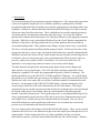
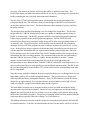
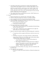
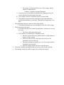
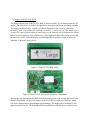
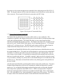
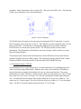
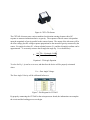
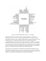
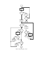
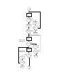
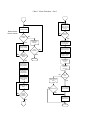
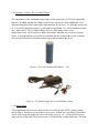
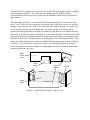
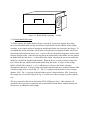
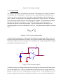
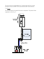
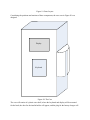
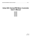
Design Team 2 Automated Syringe
Loading Device
Alternative Design Report #3
Client Contact:
Dr. John Enderle
Biomedical Engineering, University of Connecticut
Email: [email protected]
Phone: (860) 486-5521
Daniel Littleton, Scott Relation, and Kathryn Tempe
11/3/2007
1.1 Introduction
This is the third proposal for an automated syringe loading device. The automated syringe loader
is a device designed to simplify the lives of diabetes patients by enabling them to fill their
prescriptions without the help of another person, thereby supplying them with independence and
confidence. Diabetes is a disease that affects the body and its blood sugar level, and it currently
affects more than 20 million Americans. Those with diabetes have trouble naturally producing
or utilizing insulin, a hormone that transforms sugar into energy. To correct this, diabetes
patients need to monitor their blood sugar levels, and inject themselves with appropriate amounts
of insulin. While this is not a particularly difficult task in and of itself, diabetes compounds the
difficulty of this task by affecting patients with a list of other problems that can include low
vision and trembling hands. These problems make filling a syringe with accuracy very difficult.
The device will assist patients by filling insulin syringes for them. All the user has to do is load
syringes into the device, one at a time, and load an insulin bottle into a specially designed holder.
With these materials, the loader will take insulin dosage amounts from the user that range from 0
to 100 units, increase in increments of 0.1 units, and automatically fill the syringe for the user
precisely, with accuracy within 1/1000th of a milliliter. For ease of use, this device will
implement a voice output, large character controls, and a clearly visible display.
The third alternative design for the automated syringe loader features many changes and
improvements over previous designs. First of all, the display and input controls have been
changed to a graphical LCD, and a 4x4 programmable keypad by Comfile Technology. The
display intended for use is the GLK12232-25-WBL graphical LCD display. It is a small display
but with the use of available font types and sizes, the characters will be maximized on the screen.
With the use of the voice output, the user will have a different method of communication with
the device. An advantage to the GLK12232-25-WBL display is that the dimensions of the
overall casing of the device will not be influenced by the size of the display. This design
communicates by an external microprocessor that also directly communicates to the user through
the keypad, unlike the previous designs where the communication is dependent upon the
monitor’s specified microprocessor. The keypad being used is a 4x4 programmable keypad. By
using a programmable keypad, the team will be able to specify the communication between the
user and the device, similar to the previous intended touch screen keypad. However, this is
much different than previous keypads being used because it is an external one, whereas the
previous were all contained in the touch screen monitor.
The voice output used for this design is the DoubleTalk RC8660 chipset. This is a text-to-speech
synthesizer that will receive text from the microprocessor and output speech through the use of a
simple speaker. Earlier designs called for voice input capabilities, but this was deemed
unnecessarily expensive, given that many diabetes patients may have trouble using it. Diabetes
can cause voice tremors in patients, and lower their ability to speak loud and clear. The
DoubleTalk chipset will make interaction with the device easy by converting text to speech, and
loudly presenting the user with clear instructions and information.
The use of the CXTA02 tilt orientation sensor will determine the proper positioning of the
syringe-loading device. The difference from previous designs is that this is a self-contained
device that connects to the circuit. The sensor determines the magnitude of gravity parallel to
the sensor element.
The microprocessor and the programming were also changed for design three. The previous
design utilized a CUBLOC microprocessor that was capable of running programs written in
BASIC or Ladder Logic. The BASIC programs utilized a serial processing method while the
Ladder Logic programs used a parallel processing approach. The PIC24FJ128GA006
microprocessor that is being considered in this design will be able to run programs written in C
or assembly code. The processing flow will be mainly serial in natural; the use of hardware
interrupts however will allow programs to react to changes in sensors, key presses, etc. as they
occur. In the previous design a separate clock/calendar chip was needed to provide the device
with the date/time information that was required when storing syringe dosage data. Since the
PIC24 microprocessor has a built in Real Time Clock/Calendar module which can provide this
information, this chip is no longer needed. The current microprocessor has less total memory
than the CUBLOC processor (128Kb vs. 200Kb), but that shouldn’t be an issue. Unused
memory on the DoubleTalk sound synthesizer chip can be accessed and used by the
microprocessor to store additional data. Both the CUBLOC and the PIC24 microprocessors can
interact with external devices using parallel port and serial port communication. The PIC24 also
has two Inter-Integrated Circuit modules (I2C) which can be used for communicating with other
device components.
Since the energy needs have changed, the power supply for the device was changed from several
large battery packs to a few small rechargeable batteries. The previous device’s design used
relatively bulky and heavy rechargeable batteries. The Li-Fe-PO4 batteries used in the current
design take up approximately 40% less space than the previous batteries and weigh 30% less,
while providing the syringe loader with the same amount of power.
The bottle holder assembly was re-designed to make it more accessible and make the bottle
insertion/removal process more intuitive. Instead of a top case approach, in which the bottle is
dropped into and lifted out of the case, a hinge cover is now being used to provide access to the
inside of the bottle holder assembly. The process of changing bottles has been modeled after the
same steps that are typically followed to change C or D size batteries.
This holding unit needs to interact with the syringe, by having the needle puncture the bottle lid
for insulin extraction. To do this, the insulin holder has been set onto tracks, which it will move
along to reach the syringe needle. A small servo moves the bottle and holder as a unit towards
the needle a short distance, which varies depending upon the size of the needle.
Probably the biggest improvement to the syringe loader implemented in this third design is the
syringe cartridge. This is an internal extruded pentagon that holds up to five syringes in place for
the user. The cartridge holds one of five syringes to the motor for filling, and then rotates to
present the filled syringe to the user at a window on the side of the device. Each syringe is held
in place by a simple clip and two stabilizing prongs, in one of five positions along the cartridge
sides called bays.
Since the cartridge has to turn to move syringes from the user to the insulin bottle, the motor had
to be disengaged from the syringe bay during movement. This was accomplished by housing the
motor in a casing along with a potentiometer that is used to monitor its movement. These
enclosed parts move along tracks by way of a servo, to and from the syringe for loading. The
motor and potentiometer work together the same way they did in the previous design, and the
plunger grip still works by being pulled along a screw.
1.2 Subunits
All of the parts in this design work together to carry out the actions outlined here. These are the
action steps of the syringe loading device.
1) Load Syringes
a. The user can go to the main menu of the device, and select “Load Syringes”
b. The user selects “Load New Syringes” or “Replace Syringes”
i. “Load Syringes” moves to step 1e
ii. “Replace Syringes” tells the device to move the cartridge to an empty bay
so a larger syringe can be placed
1. The syringe size is detected by an extra sensor on the syringe bay
2. If no bay is empty, the device moves to syringe bay 1, and the user
replaces the syringe with a larger one
3. After the syringe is replaced, the user presses “OK” and the device
proceeds with the next step
c. If the user continues with the loading process without inserting syringes, and
when filling is about to begin, the device realizes the syringe cartridge is empty, it
will go to the load syringes screen, and follow the same steps as the “Load
Syringes” selection
d. All syringe bays on the cartridge will have sensors to detect the presence of
syringes.
e. The device will check the sensors, and any bay that does not have a syringe will
rotate to the user window, starting with a default bay ( called “syringe bay 1”) and
progressing in one direction from this initial bay to syringe bays 2 thru 5
f. After lining up the plunger grip of the device with the plunger handle of the
syringe and the syringe supports of the device with the syringe handle, the user
pushes the syringe into the bay, until the grips “snap” onto the cylinder of the
syringe. Once the user has placed a syringe into a previously empty bay, they
press the OK button on the screen (or any equivalent button to be later selected),
and the cartridge turns to the next empty bay
g. This continues until all bays are full OR the user presses “finish” button (or any
equivalent button to be selected later)
2) To load
a. The user turns the device on, and selects the “Load Syringe” option
b. The device checks the syringe bays to make sure a syringe is available
c. User is prompted by the device to input the desired amount of insulin
d. The device displays, and speaks, the volume selected by the user, and prompts the
user to decide if the amount displayed is correct
i. If yes, the device proceeds to step 2e
ii. If no, the device returns to step 2c
e. The current insulin bottle is checked for volume
i. If the volume of insulin in the bottle can accommodate the desired dosage,
the device proceeds to step 2f
ii. If the volume is insufficient, the device prompts the user to replace the
bottle with a new one, then returns to step 2d
f. The device rotates the syringe cartridge to the default starting point, “syringe bay
1”
i. If syringe bay one has a syringe of sufficient size, the device moves on to
step 2g
ii. If a syringe is not present, or the syringe in that bay is smaller than the
dosage requested by the user, the cartridge rotates to the next bay with an
available syringe, and then moves on to step 2g
1. If every bay in the cartridge is checked, and no syringes are
present, the device returns to step 1
2. If no syringes of adequate size are detected, the device displays a
message “The syringes are too small. Please replace one with a
syringe of adequate size, or split your dosage into smaller
amounts.” The device then returns to step 1b(ii)
g. A servo moves the motor assembly to the syringe, so the motor can interact with
the plunger grip
h. The comparator circuit is prepared
i. The device calculates the amount of insulin as a distance the plunger must
travel
i.
j.
k.
l.
1. The distance is determined by the size of the syringe, and the
volume of insulin desired
(volume) = π(radius of syringe)2(distance)
ii. The device uses a calculation to determine the voltage put out by the
resistor when the desired length as been met
iii. This voltage is sent to a comparator circuit, to be used later
iv. The number of steps the motor must make to move the plunger the
predetermined distance is estimated. This number of steps is the cut to
80%.
The insulin bottle drawer is moved to the syringe needle
i. The distance the bottle moves is determined by the size of the syringe
The device powers the motor
i. The motor turns the screw and the potentiometer, which moves a nut on
the screw
1. This screw pulls on the plunger grip
ii. The resistance is sent through a comparator circuit
1. The device powers the screw until for the 80% of the estimated
number of steps required
2. After these steps are taken, the motor slows down, so the
comparator circuit can keep up
3. The motor continues to turn the screw at a slower pace until the
comparator circuits match
4. Once the voltages match, the device stops the motor
The motor assembly and insulin bottle are moved away from the cartridge
The cartridge rotates the loaded syringe to the window for removal
1.2.1 Display: GLK12232-25-WBL
The display chosen is the GLK12232-25-WBL by Matrix Orbital. It is a simple graphical LCD
display. The GLK12232-25-WBL is designed to be the display unit for an associated controller.
The microcontroller will have control over what is displayed on the screen by connection
through I2C port. The module size is 98 mm x 60 mm x 13.5 mm (l x w x t). The display size is
76 mm x 25.2 mm, which is relatively small, however, the font size will be maximized to fill out
the screen and to appeal to users of the device. The background color of the screen is white and
the text color is blue. Since the display is a bit mapped device, graphics would be able to be
displayed, if the team chose to do so.
Figure 1: GLK12232-25-WBL (front)
Figure 2: GLK12232-25-WBL (back: Electrical Components)
Through the use of programming, different text fonts and graphics can be used and stored in the
display’s flash ROM. In power-off modes, the device is able to retain such selections, which
will not be changed unless done through reprogramming. The display has a backlight for lowlight areas that it is used. The backlight will be on indefinitely while the device is powered on.
Adjusting the contrast of the screen can be used to determine the best seeing capabilities for the
users of the device. To maximize the display features of the GLK12232-25-WBL, Matrix
Orbital offers an interface program that is used to manage font and graphics downloads. This
program, “mogd.exe” is provided by CD and a PC can be used to select these features, which are
incorporated into the programmed microprocessor.
The GLK12232-25 receives characters and positions them one after the other, as they are
received. The feature “auto scroll” will be used to shift the display’s contents up to make room
for a new line of text when the text reaches the scroll position set by the “Set font metrics” in the
display memory. The “Set font metrics” command is used to determine where on the display the
characters will begin to be displayed.
The display also allows the programmer to test the display by connecting directly to a PC. To do
so, a PC cable along with the required 5 V power supply is required. To successfully test the
display, characters on the keyboard typed should appear on the display of the GLK12232-25.
However, keys such as backspace, delete, and clear will not have an effect on the input to the
display during testing. The screen displays characters by wrapping the text around to the next
line when the end of the line has been reached, which is dependent on the font size being used.
This feature can be used to select the appropriate font style and size that will work best for
patients with visual disabilities.
1.2.2 Data Input: 4x4 Programmable Keypad
The keypad chosen to communicate between user and the syringe-loading device is a 4x4
programmable keypad by Comfile Technology. The size of the keypad is 76.3 mm x 68.8 mm.
If desirable, extensions can be made off of the keys to enlarge them, making it more accessible to
users with disabilities that may inhibit the correct selection. The team will program the device
with numbers 0 through 9, “.”, “YES”, “NO”, “ENTER” and “CLEAR”. The keys will be
appropriately labeled in English letters as well as Braille.
Figure 3: 4 x 4 Programmable Keypad
Keystrokes are first routed through the microcontroller before displaying on the GLK12232-25WBL. The keypad connector will be wired with columns on one side and rows on the other side
of the connector. They keypad will be directly connected to the PIC24 chip.
Figure 4: Pin Layout of Customizable Keys
1.2.3 Text-to-Speech Output: DoubleTalk
The DoubleTalk chip RC8660 by RC Systems will be used as a voice synthesizer. This
component is required by the design because the device must be able to read input prompts, input
values and verification prompts. The DoubleTalk chip is a text-to-speech processor that
translates pain English into speech in real time. The chip does not require a PC or high-powered
processor to work. DoubleTalk RC8660 requires 4 mA of operating current at 3.7 V to run and
as little as 0.7 μA when not in use. The RC8660’s audio output would be in analog format for
simple instructions and questions for the user of the device to answer by keypad.
Commands for the DoubleTalk RC8660 will be selected based on user disabilities that are using
the syringe-loading device. The speech rate will be adjusted to a rate between slow and medium,
most likely 2 or 3S where 0S is the slowest rate,13S the fastest, and 5S being default. The one
voice chosen, of the available 11, to speak the text instructed by the microprocessor will be one
that has a favorable pitch and tone. An audible “reminder” option can also be selected to sound
every ten minutes, resetting every time the device has finished being used, to remind the user that
the device is on. This feature can benefit the total device by allowing power-saving abilities on
the user’s behalf.
All of the data for the RC8660 is sent through the built-in serial and/or parallel ports. The chip’s
Peripheral Input/Output Bus will be used to communicate with the microprocessor’s parallel
master port. It is an eight-bit bidirectional peripheral bus that sends text, data and commands.
Data is input from a peripheral when PRD# is active. PRD# is an output called “Peripheral
Read” that controls the transfer of data from a peripheral to the RC8660. Data is read from the
PI00 – PI07 when PRD# is low. Status information is output when STS# us active. The STS# is
an output “Status” that controls the transfer of status information from the RC8660 to a
peripheral. Status information is driven on the PI00 – PI07 pins when STS# is low. This function
is only active when there is new status information.
Figure 5: RS-232 Interface
The RC8660 chip will connect to the microprocessor through a RS-232 connection. A typical
RS-232 interface can be seen above in Fig. 5. The CRS# pin is used to control the flow of serial
data to the RC8660. All of the data is sent through a high-speed 16-byte buffer within the
RC8660 before it is stored in the primary buffer. The TXD pin provides real-time status
information. The information is transmitted as one-byte messages, which correlate to a status
flag in the Status Register.
The microprocessor controls all of the interactions with the RC8660 over the system data bus
using the read (RD) and write (WR#) signals. RD controls the reading of the RC8660’s Status
Register and WR# controls the transfer of data into the RC8660 DoubleTalk chip.
1.2.4 Orientation Sensor: CXTA02
An orientation sensor is required by the device to assure that the device is standing properly in
order to load the syringes with insulin. Without such a sensor, the possibilities of loading air
instead of insulin are possible if the insulin vial is not in a downward direction. The sensor
intended for use is the CXTA02 by Crossbow and is a dual axis analog tilt sensor. The CXTA02
has a small size of 24.1 mm x 50.8 mm x 30.5 mm and is packaged in a lightweight aluminum
case. It can be affixed to the inside of the syringe-loading device by screws or adhesive. The
sensor uses a 5 V power supply. The device has great accuracy to within ± 0.5° over the angular
range. The device can make angle measurements up to 75° in tilt range.
Figure 6: CXTA Tilt Sensor
The CXTA02 tilt sensor uses a micro-machined acceleration-sensing element with a DC
response to measure inclination relative to gravity. The response of the tilt sensor is dependent
upon the magnitude of gravity parallel to the sensor element. The output of the tilt sensor will be
an offset voltage plus the voltage response proportional to the amount of gravity measured by the
sensor. For angles less than 20°, a linear relation between Vout and the tilt angle in radians can be
approximated. To accurately measure the tilt angle the angle Eq. 1 is evaluated for φ.
φ=
)⎤⎥
180 ⎡(Vout − ZeroAngle Voltag
⋅⎢
π ⎢⎣
Sensitivity
⎥⎦
Equation 1: Tilt Angle Equation
To solve for Eq. 1, φ can be set to zero, and therefore the device will be properly orientated
when:
Vout = Zero Angle Voltage.
The Zero Angle Velocity will be calibrated before use.
Figure 7: Pin Diagram for CXTA02
By properly connecting the CXTA02 to the microprocessor board, the information can complete
the circuit and the loading process can begin.
1.2.4 Microprocessor: Microchip’s PIC24FJ128GA006
Microchip’s PIC24FJ128GA006 was selected as the microprocessor to use for the current design
of the syringe loading device. Below is a list of the microprocessor’s main features, (see Table
1). Following the table is a diagram of the microprocessor’s pin layout, (see Fig. 8).
Speed
Up to 16 MIPS at 32
MHz
Memory
200 Kb
Flash Program Memory Retention
20 years
Programming Languages
Assembly Code and C
Pins
64
Parallel Master/Slave Port
8 or 16 bit data
Serial Port Interface Modules
2
UART Modules
2
Inter-Integrated Circuit Modules
2
10 bit Analog-to-Digital Converter
16 Channels
16 bit Timers/Counters
5
Comparator Modules
2
16 bit Capture Inputs
5
16 bit Compare Outputs
5
External Interrupt Sources
5
Input Change Notification
Real-Time Clock/Calendar Module
Table 1: PIC24FJ128GA006 Microprocessor Features
Figure 8: PIC24FJ128GA006 Microprocessor - Pin Diagram
The PIC24 will interface with all of the device’s electrical components. It will receive
information from the various sensors and the keypad through use of its Capture Input ports.
Input Change Notification will be configured for these ports to allow the microprocessor to react
to changes in status. Communication with the GLK12232-25 graphic display will be
accomplished through the use of one the built-in Inter-Integrated Circuit modules. Commands
and data will be sent to the DoubleTalk sound synthesizer chip via the PIC24’s Parallel Master
Port. Status messages from the sound chip can also be received through this port. If additional
memory is needed for storing dosage information, available memory space on the DoubleTalk
chip can be accessed and written to using the PIC24’s Parallel Master Port.
The microprocessor will also be able to communicate with a computer through the use of its
Serial Port Interface module (SPI). An R-232 port will be linked to pins for one of the PIC24’s
SPI modules. A standard serial cable will be able to connect the syringe loader’s R-232 port to a
computer’s serial port; this will enable data to be transferred between them.
The servos and motors of the syringe loader device will be able to be controlled using the
PIC24’s Output ports. These ports are capable of generating both single and continuous output
pulses. Since the motors require 6 volts to operate them they will not be able to be directly
powered by the microprocessor (its normal operating voltage is between 2 and 3.6 volts).
Instead the outputs will trigger transistors to “open” and to allow the necessary current/voltage to
be sent to the motors.
The microprocessor will perform several functions during the operating of the syringe loader’s
plunger motor:
•
•
•
•
•
•
It will first need to use the syringe’s size and the user’s requested dosage amount to calculate
what voltage the mechanical potentiometer (which is attached to the plunger arm) should be
generating when the correct amount of insulin is withdrawn.
The PIC24 will then compute the number of steps the plunger’s stepping motor will need to
complete until 80% of the voltage/distance is reached.
The microprocessor will then operate the motor in “quick” mode for the number of turns it
takes to reach 80% of the voltage.
At that point the PIC24 will send commands to a digital potentiometer, causing it to generate
the “target” voltage of the mechanical potentiometer.
The voltage from the digital potentiometer will be compared to the mechanical potentiometer
using the one of the microprocessor’s comparator modules. If the “target” voltage has not
been reached, the plunger motor will be powered for one turn, and the processing will pause
briefly before evaluating the comparing the voltages again.
Once the “target” voltage is reached, the digital potentiometer’s resistance/voltage is returned
to zero and program processing resumes.
The PIC24 microprocessor can run programs compiled for it by Microchip's Application Maestro
software. This software can incorporate assembly language or C programming files, and can
include references to functions in pre-compiled code modules/libraries. Several pre-built code
modules can be directly downloaded from Microchip’s website. These code modules greatly
reduce the amount of effort needed developing programs for the microprocessor. Serial and
parallel port communication can be accomplished through the use of functions at high level; as
opposed to having to read and set pin data values individually, and needing to trigger transfer
signal pluses directly. One a program is written and compiled in Application Maestro it can be
downloaded to the microprocessor using its In-Circuit Serial Programming module. Below is a
flowchart that outlines the major processing steps for the syringe loading device’s program.
Main Menu
No
Display Last Dose
Information
No
No
View Next
Dose
Information
View Previous
Dose
Information
Yes
Proceed to
Prepare
Dosage
Yes
Get Data from
Bottle Touch
Sensor
Insulin Bottle
Loaded
No
Prompt for Bottle
Yes
Display Prior Dose
Information
Dose
Cancelled
Yes
Display Next Dose
Information
Display Bottle
Amount
Remaining,
Ask if Correct
Bottle Amount
Correct
No
Yes
No
Yes
Store Bottle
Amount
Get Data from the
Syringe Rear
Touch Sensor
Prompt for Bottle
Amount
Get Bottle Amount
from User
Display Bottle
Amount Entered,
Ask if Correct
Dose
Cancelled
Yes
Chart 1: Menu Flowchart – Part 1
No
Get Data from the
Syringe Rear
Touch Sensor
Syringe
Present
No
Prompt for Syringe
Yes
Dose
Cancelled
Display Last Dose
Amount, Ask if
Correct
No
Yes
Main Menu
Dose Amount
Correct
Yes
Yes
Get Data from the
Syringe Front
Touch Sensor
No
Prompt for Dose
Amount
Dose > 50
Units
No
Dose
Cancelled
Yes
No
Dose Amount
Exceeds Syringe
Capacity, Re-enter
Display Dose
Amount Entered,
Ask if Correct
Yes
Dose Amount
Exceeds Available
Insulin, Re-enter
Get Dose Amount
from User
Main Menu
100 Unit
Syringe
Present
Yes
No
Dose > Bottle
Amount
No
Chart 2: Menu Flowchart – Part 2
Get Data from
Orientation Sensor
Device is
Vertical
No
Prompt User to
Orient Device
Vertically
Yes
Ready to Load
Syringe, Ask to
Confirm Load
Dose
Cancelled
Load Syringe
Confirmed
No
No
Yes
Main Menu
Yes
Get Data from
Bottle Touch
Sensor
Double-Check
Bottle Present
Bottle Present
No
Prompt for Bottle
Double-Check
Syringe Present
No
Get Data from the
Syringe Rear
Touch Sensor
Dose
Cancelled
Syringe
Present
Prompt for Syringe
Yes
No
Dose
Cancelled
Yes
Main Menu
Yes
Main Menu
No
Chart 3: Menu Flowchart – Part 3
Operate Syringe
Motor to Remove
Syringe from the
Bottle and Present
it to User
Get Data from
Orientation Sensor
Double-Check
Device Vertical
No
Device is
Vertical
Yes
No
Yes
Prompt User to
Orient Device
Vertically
Operate Servo to
Remove Bottle from
Syringe Needle
Operate Syringe
Motor to Insert
Syringe in Bottle
Dose
Cancelled
No
Syringe
Inserted in
Bottle
Yes
Syringe Ready
for User
Operate Servo to
Remove Plunger Motor
Claw from Syringe
No
Rotate the Syringe
Cartridge to Present
Syringe to User
Yes
Main Menu
Prompt User to
Take Loaded
Syringe
Operate Servo to
Move the Bottle to
Syringe Needle
Ask if Load/
Dosage was
Successful
Operate Servo to
Grip Syringe
Plunger Head
No
Calculate Distance
to Move Syringe
Plunger
Operate Plunger
Motor
Ask if Insulin was
Drawn from the
Bottle
No
Insulin Drawn
No
Plunger
Distance
Reached
Yes
Syringe Load/
Dose
Complete
Yes
Store Dose
Amount and Date/
Time Information
Yes
Adjust Remaining
Bottle Amount
Main Menu
Chart 4: Menu Flowchart – Part 4
Chart 5: Menu Flowchart – Part 5
1.2.5 Batteries / Charger: The 32v Smart Charger
The components for the automated syringe loader will be powered by Li-Fe-PO4 rechargeable
batteries. In adding together the voltage needed for the various electrical components it was
determined that the device would require approximately 30v of power. To meet this energy need
10 Li-Fe-PO4 rechargeable batteries, (each capable of providing 3.2v), will be bundled together
into a battery pack. The 32v Smart Charger for Li-Fe-PO4 battery packs, (from
BatterySpace.com), will be used to re-charge the batteries when the user is near an electrical
outlet. A charging interface port will be incorporated into the syringe loader’s case so that the
user will not need to directly handle the battery pack when charging the device.
Figure 9: Li-Fe-PO4 Rechargeable Battery – 3.2v
Figure 10: 32v Smart Charger for Li-Fe-PO4 Battery Packs
1.2.6 Bottle Holder
This component needs to securely hold a bottle in a vertical position while a syringe extracts
insulin from it. In order to accommodate a wide variety of bottle sizes and shapes, foam rubber
will be used to grip and support the sides of the bottle, (see Fig. 11). A spring will be used to
apply pressure to the bottle’s bottom to ensure it is flush with the syringe needle port. The head
of the bottle will be supported by a neck cone, which will assist in centering the bottle’s opening
over the syringe needle port. The completed bottle holder assembly should be able to
accomidate bottles that are between 12 mm to 40 mm in diameter, and between 40 mm and 70
mm in height.
The bottle holder assembly is accessible to the user through a hinged cover on the back of the
device’s case. The cover can be opened by pressing in on the catch in the center of its side and
flipping it away from the case. As the cover opens, the foam rubber attached to the inside of the
lid will be lifted away to expose the bottle area. The bottle can then be slid backwards to
compress the spring and result in the head of the bottle clearing the neck cone support structure.
Once clear of the neck, the bottle can be lifted out of the holder assembly. Bottle insertion would
involve placing the bottle’s bottom against the spring and compressing it, positioning the bottle
head into the neck cone, releasing the bottle, and closing the cover to the holder assembly. This
approach to bottle insertion and removal was modeled after the process that’s typically followed
to replace C or D size batteries in most electrical devices. By basing the bottle replacement
process on steps that are fairly well-known it is hoped that most users will find the bottle holder
assembly simple and easy to use.
Bottle
Holder
Cover
Cover
Catch
Foam
Rubber
Neck
Cone
Insulin
Bottle
Figure 11: Bottle Holder Assembly – Interior View
Spring
Figure 12: Bottle Holder Assembly – Closed
1.2.6 Insulin Bottle Movement
To fill the syringe, the insulin bottle will move towards it. In previous designs, the syringe
moved to the insulin bottle, but this would have been difficult with the addition of the syringe
cartridge, so the simpler action of moving the small bottle holder was chosen for this design. To
accomplish this action, the holder will be made with small groves along the bottom, which will
slide along tracks laid in the device case. A servo will move the holder along these tracks to and
from the syringe needle. After the user has placed an insulin bottle in the holder, the user pushes
the holder back into the device. As the holder slides inside, a hook on the servo arm catches the
holder by a small loop attached to the bottom. When the device is ready to load a syringe, the
servo lowers the arm, and the bottle holder slides along the tracks. A sensor on the syringe
holder will tell if the syringe is ½ or 1cc, and the servo will move the holder a distance
determined by this size. A larger syringe will require that the bottle move a shorter distance than
a smaller syringe will, as seen in Fig. 13. The ½ cc syringe needs the bottle to move a longer
distance, ΔXa. The 1 cc syringe needs the bottle to move a shorter distance, ΔXb. Sensors on
the syringe bay, seen as blue squares in Fig. 13, tell the device that a syringe is present, and the
size.
The servo chosen for this task is the Futaba S9252 All-Purpose Servo. This selection will
provide the necessary power required to move and hold the insulin bottle, without drawing too
much power or adding too much weight.
ΔXb
ΔXa
Figure 13: Syringe and Bottle Action
1.2.7 Syringe Cartridge
The syringe cartridge is the biggest change seen in this design. It is an extruded pentagon, with
each side containing a syringe bay. Each of these bays has two sensors, a syringe clip, and two
syringe stabilizers (see Fig 14). The first sensor is used to detect the presence of a syringe. If the
sensor does not detect a syringe, the device knows that bay to be empty. When loading is about
to occur, the device will cycle through the syringe bays until a syringe is located for filling.
When the user wishes to add more syringes to the cartridge, the device will present the empty
bays to the user. The second sensor detects the size of the syringe. When a ½ cc syringe is in a
bay, it does not depress the second sensor. A 1cc syringe, however, will depress the second
sensor. This information is used to tell the servo that moves the insulin bottle how far to travel.
When the device is ready to load, it will move the syringe bay in position below the insulin
bottle, then lower the bottle the required distance. This information is also used when the user
inputs the dosage amount they require. If the syringe in the bay is too small to hold the requested
dosage, the device will search the bays for a larger syringe.
Syring Clip
Foam
Sensor 2
Sensor 1
Figure 14: The Syringe Bay
The cartridge was designed with a stepper motor located in the middle (see Fig. 15). This allows
the device to rotate without extra parts, and saves space in the case. This stepper motor is an
Applied Motion size 23 Stepper Motor (#4023-819). It will be able to rotate the cartridge to
precisely place the syringe bay in position, so that the syringe is below the insulin bottle and in
line with the plunger grip. The motor holds fast to the cartridge with a 5-point wheel that
attached to 5 spots on the cartridge. Using this many connection points prevents slipping, and
makes sure the device stays attached, in case one point of contact fails.
The syringe clip is an adjustable adhesive-backed wire clamp made by Micro Plastics, Inc (part #
22AAwC310400). Its design was modified for use. A ring of foam rubber was inserted into the
middle to grip the syringe tightly, without crushing it. The two stabilizers (seen in Fig. 15) work
to hold the syringe up when the plunger is being pulled down. These are simple two plastic rods
that have been inserted into the syringe cartridge.
Figure 15: The Syringe Cartridge
1.2.8 Syringe Loading
The syringe is loaded by a claw pulling on the plunger. This plunger claw operates in a manner
very similar to the second design. A motor turns a screw and a potentiometer simultaneously.
As the screw turns, a nut on the screw is forced up or down depending on the direction of the
screw’s rotation. As the nut moves, the plunger claw attached to it moves as well. This motion
moves the syringe plunger when the claw and plunger are together. The simultaneously rotation
potentiometer increases in resistance as it turns, which is used in a computer program to
determine the distance traveled by the plunger. First, the potentiometer is hooked up to an
inverting amplifier, like the one shown below, in Fig 16. Using the equation of gain for inverting
amps,
Equation 2: Gain of an Inverting Amplifier
and by locating a potentiometer at the position Rf changes the output voltage of the circuit. As
the motor turns, the potentiometer’s resistance value increases, and the output voltage increases.
This output voltage is sent to the computer to be compared to the voltage coming from the digital
potentiometer, described in section 1.2.4.
Ri
2
-
V-
11
Rf
Vin
+
Vout
4
3
1
V+
OUT
0
0
Figure 16: The Inverting Amplifier
To load the syringe, the cartridge rotates the selected syringe bay below the insulin bottle, and in
line with the plunger claw. After the insulin bottle has been lowered to the syringe needle, the
plunger claw then moves to the syringe plunger, and pulls it down. To get the plunger claw, and
the motor and potentiometer that are attached to it in place, a servo moves them along tracks in
the case. The set-up is seen in Figures 17 and 18. The servo is the same Futaba All-Purpose
Servo as the one used to move the insulin bottle.
Figure 17: The Motor, Potentiometer, and Plunger Grip
Figure 18: The Plunger Motor on Tracks
The motor selected is the Applied Motion size 23 Stepper Motor (#4023-819), and the
potentiometer chosen is the MW 22 Wirewound Precision Multi-Turn Potentiometer.
1.2.9 The Case
The case was designed to fit around all of the devices components. The positions of these
components are seen in Fig. 19.
Figure 19: Parts Layout
Considering the positions and motions of these components, the case seen in Figure 20 was
designed.
Display
Keyboard
Figure 20: The Case
The case will consist of a plastic outer shell, where the keyboard and display will be mounted.
On the back, the door for the insulin holder will appear, and the plug for the battery charger will
be at the bottom of the rear side. The hump on the right side of the case encloses the syringe
cartridge. Under the hump, there is a hole for the extended syringe handle. The slit that extends
the length of the bump is the window through which the syringe can be inserted or removed. A
clear plastic window will be present over this bump, to ensure nothing falls out of the device
while it is being carried, and that no dust or other foreign particles get in.
2. Realistic Constraints
The intended design to satisfy the problem faced by many diabetic patients with a variety of
conditions causes factors, based on limitations, to be followed when considering not only the
pure design of the device but the user’s capabilities. For the automated syringe-loading device,
health and safety of the user are important to keep in mind when proposing a design. The device
should be able to impact their lives in a positive way and not compromise what has already been
by their disability.
A constraint that is proposed by this design is the interaction between the user and device input
selection. A significant problem may arise if the buttons on the device require too much force
for the patient. It is therefore important that all user inputs be tested for ease of use. While voice
input is still being investigated, it seems a high cost to risk its effectiveness.
The visual display and audio output may also be difficult for the user to interact with. The
device must be tested on a number of patients to determine their comfort level with the size and
clarity of the characters. It will also be necessary for the audio output to be tested and
reprogrammed as necessary. Different voices may carry through more clearly, making it easier
for the patient to understand what is being said.
The device is intended to be portable. This requires a minimum battery life to be implemented
so the user does not come into a dilemma that may cause their health to be in jeopardy. The
device must therefore have rechargeable, or easy replaceable, batteries that allow a longer life of
the device and an increase of portability.
The size of the device is a consideration for reasons pertaining to portability and to ensure that
the user will not feel the device is a nuisance. The self-contained device should be as lightweight
as possible since some of the users do not have great strength. For active users, the device
should not hinder other aspects of life such as carrying young children and objects. By putting
the device, intended to be the size of a briefcase, in a bag that can be worn on the shoulder,
across the chest, or even in a backpack fashion, the user will be able to select their choice of style
and what is most comfortable to them.
The device should be protected in the case, in the event that the device drops to the ground or is
shaken around. The layout of the internal casing will be designed in such a way that every
component is affixed to the case and protected. The layout will also be maximized so the case is
not larger then it absolutely must be.
3. Safety Issues
Accuracy and durability of sensors is a main safety issue for the automated syringe-loading
device. Without accurate sensors, incorrect doses of insulin will most likely be drawn. Such
errors may result in too much insulin or not enough. Air bubbles will also be a product of the
errors, which will give the user false confirmation of the intended dosing. These errors can
become significant to a person who must have the correct amount of insulin.
The device should have no exposed electrical wires. The patient can be harmed in the occasion
that it produces an electrical shock. The device must also be contained in such a way that if a
spill accidentally occurred, there would not be any risk to the user. To assure that there is no
additional hazards to the user, a clear shielding made out of lightweight plastic can be used to
cover the mechanical components.
An additional safety issue is malfunction within the mechanical components. Failure in the
syringe guides could lead to miss-positioning or jamming of the syringe during loading. In
addition, failure in the bottle holding assembly could lead to misalignment of the bottle, which
could result in syringe needle damage or breakage. All have the possibility of injuring the user
of the device.
Sterilization of all syringes is an important safety consideration. Each syringe comes
individually packaged for sterilization reasons so it is therefore necessary to maintain an
environment in which the patient will know they are being protected from harmful conditions. It
may become necessary to ensure that all components will stand up to sterilization techniques,
such as chemical washing or autoclaving.
4. Impact of Engineering Solutions
As a growing number of diabetic cases occur due to various factors, such as obesity and low
physical activity on an individual’s behalf, a better design for syringe-loading devices is vital.
As a growing population ages, an additional increased risk of diabetes is present. With the
growing numbers of diabetes cases, comes an increasing number of people with disabilities.
These disabilities can greatly inhibit a person’s ability to properly inject themselves with the
correct amount of insulin. Without the correct amounts, a person’s health deteriorates and can
lead to greater risks and dangers.
There are many great consequences if a diabetes patient does not properly take care of their
condition. Strokes, blindness, heart disease, kidney failure, amputation, and nerve damage are
all possible effects caused by diabetes if untreated or not treated properly. With the use of the
syringe-loading device, diabetes patients will find their condition more easily controlled with a
device contributes to great accuracy and simplicity.
By incorporating various languages into the device, it will be able to be used on a global level.
The simple-to-use design will appeal to large numbers of people from different backgrounds.
The same features intended for users with disabilities can also be utilized by patients who may be
unfamiliar with technology or who have other lifestyles.
It is important that devices intended for all different people in different income brackets be able
to afford these essential devices. By building an affordable and simple device, many people will
benefit for the attainability of it. Widespread distribution of the device is also an important
factor. An economical device within typical syringe-loading devices is necessary because
normal insulin pumps can cost well over $5,000 not including monthly supplies and increased
doctor visits to maintain the device. By designing and building within a budget of $2,000 future
designs will be able to properly mimic while cutting down on individual components and
therefore reducing the overall price. With increased distribution of the components being used,
the device will benefit from lowered manufacturing costs.
The portability of the intended syringe-loading device allows diabetes patients to explore other
opportunities and will give them the confidence that they lacked before regaining such
independence. Allowing the user to bring the device on day trips and vacations will give them
the freedom they may have thought was gone. Such a design of portability will appeal to more
patients and help give them the confidence of receiving an accurate amount of insulin.
The accuracy of the device will allow insulin users to receive the maximum benefits from a
precise amount of required insulin. This precision can improve their everyday activities and
allow the user to receive the benefits intended by the design.
The design of the project is meant to appeal to everyone regardless of their familiarly of
technology. The intended design will allow various patients with disabilities to use the device in
a similar fashion as any other non-disabled diabetes user. The simple user instructions will
deliver an accurate dosing of insulin to all users.
5. Life-Long Learning
With greater knowledge of components that can be used to assist the designing of the syringeloading device, the team is able to explore greater opportunities to further assist diabetes patients
with disabilities. Devices that currently also help with disabilities can be modified to fit this
application appropriately by using the lessons taught in the designing of the device.
Through researching the different components for the device, many new techniques in designing
abilities were encountered. By using a different display that does not contain an incorporated
microprocessor, the team was able to explore greater programming languages and to learn and
understand how to use the current design to implement the correct steps into the program.
By using a programmable keypad, different opportunities can be explored to decide on what is
the best method to go by for appealing to an overall population. The text-to-speech synthesizer
has been able to teach the team members a new way of communicating to the user by use of the
microprocessor. The different selections incorporated into the speech output will continue aid
the team in learning about the various disabilities diabetes patients encounter and a way to assist
them in greater places than just the syringe-loading device.
6. References
[1] “GLK12232-25-WBL: Technical Manual.” Matrix Orbital.
<http://beta.octopart.com/Matrix_Orbital__GLK12232-25-WBL.pdf >.
[2] “4x4 KEYPAD.” COMFILE Technology. <http://cubloc.com/product/04_03keypad4x4.php
>.
[3] “DoubleTalk RC8660: Voice Synthesizer Chipset.” RC Systems.
<http://www.rcsys.com/Downloads/rc8660.pdf >.
[4] “Tilt Sensors: Solid State, Analog Series.” Xbow.com.
<http://www.xbow.com/Products/Product_pdf_files/Tilt_pdf/CXTA_Datasheet.pdf>.
[5] “PIC24FJ128GA010 Family Data Sheet”, Microchip Technology Inc.
<ww1.microchip.com/downloads/en/DeviceDoc/39747d.pdf>.
[6] “Section 12. I/O Ports with Peripheral Pin Select”, Microchip Technology Inc.
<ww1.microchip.com/downloads/en/DeviceDoc/39711b.pdf>.
[7] “Section 23. Serial Peripheral Interface”, Microchip Technology Inc.
<ww1.microchip.com/downloads/en/DeviceDoc/39699b.pdf>.
[8] “Section 24. Inter-Integrated Circuit”, Microchip Technology Inc.
<ww1.microchip.com/downloads/en/DeviceDoc/39702a.pdf>.
[9] “Microchip Application Maestro Software User’s Guide”, Microchip Technology
Inc.<ww1.microchip.com/downloads/en/DeviceDoc/51328a.pdf>.
[10] “DoubleTalk RC8660 User’s Manual”, RC Systems
<www.rcsys.com/Downloads/rc8660.pdf >.
[11] “GLK12232-25-WBL Technical Manual”, Matrix Orbital
<beta.octopart.com/Matrix_Orbital__GLK12232-25-WBL.pdf>.
[12] “PLC / Embedded computer - CUBLOC - User Manual Version 2.5”, Comfile Technology
Inc. <http://cubloc.com/download/CUBLOC253a.pdf>.
[13] “Precision Multi-Turn Rotary Potentiometer - MW22 Wirewound”, ETI Systems Inc.
<http://www.etisystems.com/mw22.asp.>
[14] “Applied Motion Products: Motors, Motion Control Products, Drives and Controls”,
Applied Motion Inc. <http://www.applied-motion.com/products/stepper/motors/size23.php>