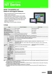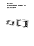
1
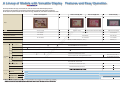
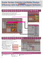
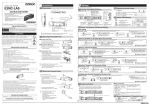
NT20
NT31/ 31C-V3
NT631C-V3
Series
on
l
in
ec
om
po
ne
nt
s.
co
m
Better SYSMAC Compatibility and
Easier-to-use Support Software
Providing What's Needed in
Programmable Terminals
on
l
in
ec
om
po
ne
nt
s.
co
m
The Simple Design and Easy
Operation That Users Need.
Reduced TCO* throughout Onsite System Construction and
Maintenance.
2
To keep in pace with the progress of information technology
on production sites, more advanced and more diversified
functions are continuously required from operator interfaces.
OMRON continuously researches the use of operator interfaces at all stages of application. OMRON scrutinizes system
compatibility, design efficiency, operability, and maintenance, and helps reduce the TCO for the introduction, maintenance, and management of systems.
The NT Series of Programmable Terminals ever continues to
improve functionality from the users' perspective.
*TCO (total cost of ownership)
Improved SYSMAC Compatibility
Device monitoring and I/O comment loading functions facilitate
system construction.
Easier Screen Creation and Better
Design Efficiency
Greatly enhanced NT Support Software with reusable screen data
and powerful simulation on editing screens.
Easier On-site Maintenance
Transfer the system program and screen data to ensure smooth
on-site system maintenance and improve the efficiency of onsite work.
Wide Range of Communications
Interfaces
3
A Lineup of Models with Versatile Display Features and Easy Operation
The lineup includes one large, two medium-size, and one small PT with different display devices.
The functions and operability of all models are unified, making replacement with another model easy.
Screen data from previous models can be used for all large, medium-size, and small PT models in the series.
NT31C-ST143(B) -EV3
NT631C-ST153(B)-EV3
NT31-ST123(B) -EV3
NT20-ST121(B)
211 x 158 mm
Number of dots (resolution)
640 x 480 dots
Max. number of touch switches
32 x 24 switches
po
External interface
in
ec
CJ1 , CS1H, CS1G, C200HX(-Z), C200HG(-Z), C200HE(-Z), and SRM1-EV2
Host Link
Mitsubishi FX Series
CJ1 (-H), CS1 (-H), C200HX(-Z), C200HG(-Z), C200HE(-Z),
C200HS-CPU2 , C200HS-CPU3 and CS1Communications Units
on
l
From OMRON
(See note 1.)
C200HX(-Z), C200HG(-Z), C200HE(-Z), C200HS-CPU2 , and C200HS-CPU3
High-speed NT Link
Memory Link
From
Mitsubishi
Connectable
hosts
1-to-N NT Link
om
Applicable standards
1-to-1 NT Link
STN monochrome monochrome display
Mitsubishi A-Series
(Computer Link Unit)
STN monochrome display
118 x 89 mm
111.5 x 57.6 mm
320 x 240 dots
256 x 128 dots
16 x 12 switches
12 x 6 switches
nt
Effective display area
STN color display
s.
TFT color display
ne
Display
co
m
Model
RS-232C, RS-422A, RS-485, and printer port
2 RS-232C ports
cULus standards, EC Directives, and C-Tick
CQM1-CPU4 , CPM1A, CPM2A/C, SRM1, CVM1/CV Series (EV1 or EV2),
and C200HX/HG/HE Communications Boards
CS1 Communications Unit and CQM1H Communications Board
CJ1 , CS1H and CS1G
CQM1-CPU4 , CQM1-CPU2 , CPM1A, CPM2A, CPM1C, SRM1, CVM1, CV series (EV1 or EV2),
C-series/CV-series/CVM1 Host Link Unit
Personal Computer, SBC, and Programmable Controller
Personal computer, SBC, or
PLC (RS-232C) (See note 5.)
MELSEC FX1, FX2, FX2C, FXO, and FXON
AOJ2-C214S1, A1SJ71UC24-R2,
A1SJ71UC24-R4, and AJ71UC24
Allen Bradley (DE1)
SLC 5/02, 03, 04, and 05 (See note 2.)
GE-Fanuc (SNP-X)
90-20 and 90-30 Series (See note 2.)
Siemens (Via HMI Adapter)
Japanese
Language
English
Simplified Chinese
(See notes 3, 4, and 5.)
Traditional Chinese
(See note 3.)
Note
2: The English version of the NT Support Tool must be used.
4
4: Purchase the NT20-ST121(B)-EC to display simplified Chinese on the NT20.
5: A separate system program must be installed in the NT20 to use RS-232C memory links with the NT20. Simplified Chinese is not supported.
5
Improved SYSMAC Compatibility for
Easier System Construction
Programming Console and Device Monitor Functions
Registration
monitor
[Device Monitor]
s.
co
m
The device monitor function makes it possible to read and
write I/O memory data and display consecutive sections of
PLC data areas. This function greatly improves the efficiency
of PLC setup work, including set value input into the Special
I/O Units and checks on the settings. Data can be read from
I/O memory from a user-created screen to enable application
on maintenance screens for monitoring.
nt
SYSMAC
[Programming Console Functions]
po
C-series and CS/CJ-series ladder programs can be written
and read in mnemonic form through the NT631/NT31
screens for easy on-site system maintenance.
ne
PT
in
ec
om
Error log
Continuous
monitor
on
l
I/O Comments Can Now Be Imported
I/O comments can now be imported from ladder program
files, such as CX-Programmer files. Imported I/O comments
can be used as labels to eliminate the bother of entering
comments. This also prevents I/O allocation mistakes between the PT and PLC, and reduces the time required to correct such mistakes.
CX-Programmer
PT
Import I/O Comment Dialog Box
6
Full-area Access to SYSMAC CS1/CJ1-series PLCs over High-speed NT Link
OMRON Data Comparison
Response Speed for Communications with
Single PT Connected
Host Link
co
The industry's highest serial communications speed.
Up to eight NT631/NT31/NT20 Units can be connected to a
single port.
Extends to a maximum of 500 m.
Essentially the same performance is achieved for NT Links with
eight PTs as for an NT Link with a single PT (for refreshing
numeric displays).
m
Connect to SYSMAC CS1/CJ1-series PLC
over High-speed NT Link
NT Link
s.
High-speed
NT Link
nt
SYSMAC CS1/CJ1-series (-V1) PLC
0.0
0.5
1.0
1.5
2.0
2.5
3.0
in
ec
NT31C-V3
NT631C-V3
NT Link
High-speed
NT Link
Three times
as fast
0.0
0.5
1.0
1.5
2.0
2.5
3.0
All data was measured at the RS-232C port of the CPU Unit with the
response speed for a single NT Unit connected taken as 1.
on
l
NT20
om
po
ne
Response Speed for Communications with
Eight PTs Connected
7
Easier Screen Creation and Better Design
Efficiency with Improved Support Software
Unified Screen Creation Environment with the NTST NT Support Software
co
m
Windows Look and Feel environment ensures easy operation,
allowing anyone to create screens quickly and easily.
The enhanced ON/OFF simulation function of the
NT631/NT31/NT20 and easy application of existing screen data
accelerate product development and designing.
Edit screen
om
po
ne
nt
s.
The arrow keys on the keyboard are used to move objects dot by dot.
Displays object and cursor coordinates.
The window being manipulated can be displayed or not displayed.
Zooms up to 800%.
in
ec
Application Manager
(The NT631, NT31, and NT20 are supported by NTST-V4.)
on
l
Symbol Manager
Easier Application of Existing Screen Data
It is possible to load screens and tables independently from different screen data files.
The NT631/NT31/NT20 can now use existing screen
data efficiently.
Improved Compatibility with NT30 and
NT620 Series
Image and library data coding.
Image and library data insertion into character strings.
The word configuration and
functions for the
NT631/NT31/NT20 status control area and notification area.
System Requirements
CPU: Pentium 100 MHz min.
RAM: 32 MB min.
8
Hard disk
Software capacity: 17 MB
Installer: 3 MB
Sample objects: 32 MB
OS: Windows 95, 98, 2000, NT 4.0, Me, or XP
Media: CD-ROM
Complete Functions in NT Support Software
I/O Comment Table
Double-click the error message to track down the error
on the screen.
All PLC addresses and I/O comments can be managed together.
Addresses that have been allocated are automatically registered
in the I/O comment table.
ne
nt
s.
co
m
Error Log Viewer
I/O Comment Table
Objects can be top-, bottom-, left-, right-, or center-aligned
automatically.
on
l
Online Help
in
ec
om
The filter function makes editing easier by displaying
only the objects you select for modification.
po
Object Alignment
Filter
Search Function
Click the Help icon
whenever you are not sure how
to proceed. The information you need will appear by
touching the objects on the screen.
Help
It is possible to jump from an I/O
comment table address to the screen
where the object is located.
9
Easier, More Efficient On-site
Maintenance.
Increased Backlight Life for Maintenance-free Operation
The Backlight Module has been redesigned to eliminate the need to replace the Backlight and enable
maintenance-free operation for up to 50,000 hours.
m
System Program Transfer
co
By transferring a new system program, functions
and performance can be updated without changing
hardware.
om
po
ne
nt
s.
The following system programs are provided.
OMRON (Memory Link) and Mitsubishi versions
for NT31/631
OMRON, Mitsubishi, and Memory Link versions
for NT30/620
OMRON, Mitsubishi, and Memory Link (RS-232C)
versions for NT20
in
ec
System installer
1) The compatible combinations of NT31/631 models
and system program versions are shown in the
table.
on
l
: Indicates the preinstalled default combination of
versions (recommended).
: Indicates combinations of versions that can be
transferred for operation.
: Indicates combinations of versions that can be
transferred but for which some functions are
restricted during operation (e.g., high-quality
character display).
: Indicates combinations of versions that cannot be
transferred.
2) NT31/631 system program version 4.x can be
transferred only with System Installer V2, which is
available on the CD for NT Series Support
Software version 4.08 or higher. Only system
programs up to version 3.x can be transferred with
older versions of the System Installer.
3) The NT20 system program can be transferred
only with System Installer V2.1, which is available
on the CD for NT Series Support Software version
4.8 or higher. It cannot be transferred with lower
versions of the System Installer.
10
System (See note.)
PT
Pre-V1
-V1
-V2
-V3
Ver. 1.x
Ver. 2.x
Ver. 3.x
Ver. 4.x
Note: The system version is shown in the System Installer program under "Ver." (circled in red in
the above diagram).
Special Utility to Transfer Screen Data
nt
Supports Wide Variety of Language Input
s.
co
m
It is possible for anyone to easily transfer screens
by using a special software application instead of
the NT Support Software. The software application
can be set up separately.
The NT20 system program can be transferred
using the transfer utility provided with NT Support
Software version 4.8 or higher. Change the setting
to "NT20S" if using the transfer utility provided with
Support Software version 4.0 or lower.
ne
European and English languages are supported. (The English version of the NT Support Software is used.)
Furthermore, Simplified and Traditional Chinese are supported. (The NT Support Software uses
specifications for all languages.) Contact your OMRON sales representative for details.
po
Note: Traditional Chinese is supported only by NT31/631.
om
Memory Unit for Easy and Immediate Screen Data Transfer
on
l
in
ec
Simply attach the Memory Unit to the back of the
NT631/NT31/NT20 to easily transfer screens. Up
to two banks can be registered and both system
programs and screen data can be transferred.
Check Screen Data without Programmable Controller
The NT631/NT31 displays screens, such as lamps, touch switches,
and memory table numbers, without the PLC connected, to enable efficient debugging.
Connect as a DeviceNet Slave
Connections
NT-DRT21
PLC
Interface Unit
DeviceNet compatibility means even greater
standardization.
Both I/O allocations and message communications
are supported. With a DeviceNet Interface Unit
mounted, version 1 or older versions of the
NT631/31 can also be connected to a DeviceNet
network.
Remote I/O communications
DeviceNet network
DeviceNet master
Explicit
messages
NT-DRT21
DeviceNet
Interface Unit
Connected to
Expansion I/O
Connector
NT31/631C
Programmable Terminal
DeviceNet slave
11
Wide Range of Communications
Interfaces
NT631 Series
Flat, Thin-profile Model Only
54 mm Thick
Expansion interface connector
All models have flat, smooth surfaces and are only 54
mm thick, which is ideal for space-saving designs built
into equipment.
m
Equivalent to the IP65 Oil-proof
Standard Ensures a High Degree
of Resistance to the Environment.
co
The NT631/NT31 has a flush-surface construction and
is highly resistive to severe operating environments.
The front panel conforms to IP65F oil-proof type.
RS-422A Port
Printer Port
Ensures 1-to-N RS-422A or RS485 communications, as well as
long-distance communications.
RS-232C Port
ne
nt
s.
IP: International Protection
6 : Resistant to dust (protected from solid objects)
5 : Resistant to water spray from any direction (protect
ed from water immersion)
Oil-proof type: Resistant to oil drops or sprayed oil
The NT631/NT31 cannot be used in locations where it will be subjected to oil spray
over a long period of time.
Expansion interface connector
on
l
in
ec
NT31 Series
om
po
The NT631 has two RS-232C ports that can be connected directly to bar-code readers for POP system
construction. These two ports can be used simultaneously for the Support Software and host, to greatly improve debugging and maintenance efficiency.
Printer Port
Conformity to Standards Ensures
Suitability for Exports
The NT631/NT31 conforms to UL/CSA standards and
EC Directives.
C-Tick
Protective Cover Added to
Maintenance Parts
RS-232C Port
RS-232C/RS-422A Port
(RS-232C selectable by memory switch setting.)
NT20 Series
Expansion Interface Connector
RS-232C port
RS-232C port
(used for both Support Software and host)
(host communications only)
Debugging and maintenance is more efficient using two ports.
12
Material
Polyester film
Mounting method
Double-sided tape
The Protective Cover protects the surface of the Display from oil, dust, or fingerprints.
Specifications
NT631C
Display Specifications
General Specifications
Model
Item
Rated power supply voltage
NT631C-ST153(B)-EV3
24 VDC
NT631C-ST153(B)-EV3
Model
Item
Allowable power supply voltage range
20.4 to 26.4 VDC (24 VDC –15%/+10%)
Character displays
(fixed display)
Power consumption
18 W max.
Graphic displays
65,535 per screen (including marks)
Character string displays
Up to 256 per screen (40 bytes (40 characters) per string)
Numerical displays
256 per screen, max. 10-digit display (2 words)
35% to 85% (with no condensation)
Bar graph displays
Up to 50 per screen, percentage display and sign display are possible
Ambient operating environment
No corrosive gases
Analogue meter
Up to 50 per screen, percentage display and sign display are possible.
Noise immunity
Conforms to IEC 61000-4-4 at 2 kV (power supply line).
Trend graphs
One frame per screen, 50 graphs per frame
(only 8 graphs per frame with data logging)
Broken line graphs
One frame per screen, 256 graphs per frame, 512 points per graph
Lamps
Up to 256 per screen
Image library displays
Up to 256 per screen
Up to 256 per screen, Max. overlap: 256 mesh
Ambient operating temperature
°
–
Ambient operating humidity
°C
5 to 9 Hz, single amplitude: 3.5 mm
Vibration resistance
(during operation)
2
10 times (1 octave/min) each in X, Y, and Z directions
Display elements
Storage temperature
Shock resistance (during operation)
147 m/s2, 3 times each in X, Y, and Z directions
Weight
2.5 kg max.
Touch switches
Degree of protection (front panel)
Equivalent to IP65 oil-proof type and NEMA4 (See note.)
Numeral inputs
Up to 256 per screen
Thumbwheel switches
Note: The equipment cannot be used for long periods of time in locations which expose the panel to spills of oil.
Character string inputs
Display/Panel Specifications
Effective display area
211 x 158 mm
(10.4 inches)
Automatic turn-OFF
1 to 255 minutes/None
Service life when
brightness is set to
high)
50,000 hours min. (See note.)
POWER
Green
Lit while power is being supplied.
Green
Lit during operation
Orange
Lit when the battery voltage is low (when operating)
Red
Lit when the battery voltage is low (when stopped)
RUN
Operation Specifications
Model
Item
NT631C-ST153(B)-EV3
Number of switches
768 (32 x 24)
Input
Pressure sensitive
Operating force
1 N max.
Service life
1,000,000 operations min.
on
l
Touch panel
in
ec
Note
External I/F Specifications
Item
Model
Serial port A
Serial
communications
Serial port B
Display history screens
nt
50,000 hours
(until contrast is reduced by 50%)
NT631C-ST153(B)-EV3
Conforms to EIA RS-232C.
D-sub 9-pin connector (female)
+5 V (250 mA max.) output at pin No. 6
Max. number of
registered screens
Conforms to Centronics specifications,
20-pin half-pitch connector
Expansion I/F
Dedicated connector
Order of occurrence (max. 1,024 screens), order of
frequency (max. 255 times)
Buzzer, display history, background color, backlight,
keyboard screen number
3,999 screens
0: No display
1 to 3999: User-registered screens
9000: "Initializing system" screen
9001: Display history (occurrence order) screen
9002: Display history (frequency order) screen
9020: Programming Console function screen
9999: Return to the previous screen
9021 to 9023: Device monitor
Screen No.
Screen registration method
By transmitting screen data created using the Support Tool
to the NT631C
By transmitting screen data stored in a memory unit to the
NT631C
Screen saving method
Flash memory (screen data memory in the PT)
Model
Item
NT631C-ST153(B)-EV3
Display characters
Half-size characters (8 x 8 dots): Alphanumerics and symbols
Normal-size characters (8 x 16 dots): Alphanumerics and symbols
Mark data (16 x 16 dots): User defined picture characters
Enlargement function
Normal size, double width, double height, and magnifications of
4X, 9X, 16X, 64X
Smoothing processing
Available for enlarged characters with magnification of 4X or
greater (excluding marks)
Character display attribute
Normal, reverse, flashing, reverse and flashing, transparent
Image data
Variable-size pictograph
Size: Min. 8 x 8 dots, Max. 640 x 480 dots
The size can be set in 8-dot units.
It is not possible to set enlarged display, smoothing processing,
or display attributes such as reverse/flashing.
Library data
Combination of any characters and graphics
Size: Min. 1 x 1 dots, Max. 640 x 480 dots
Any size can be set.
Enlarged display, smoothing processing, and display attributes such
as reverse/flashing are displayed according to the setting registered.
Graphics
Polyline, circle, arc, fan, square, polygon
Line type
Solid line, dotted line, alternate long and short dash, long and two
short dashes (only polylines for other than solid lines)
EIA RS-232C, (RS-422A/485 selectable by memory
switch setting)
RS-232C: D-sub 9-pin connector (female)
RS-422A/485: Terminal block (6 terminals)
Parallel I/F
Up to 3 screens (2 local windows and 1 global window) can
be displayed at the same time.
Window screens
ne
Service life
A maximum of 8 registered screens can be displayed
overlapped with each other.
Screen attributes
Number of screens
8 colors
(intermediate colors can be displayed in tiling patterns)
po
LED
Display color
om
Backlight
(cold
cathode
tube)
°
Left: 60°
Right: 60°
The normal screen display
Overlapping screens
co
640 dots (horizontal) x 480 dots (vertical)
Screen types
Color TFT LCD
Number of dots (resolution)
View angle
m
Normal screen
Display device
Up: 35°
Display
Up to 4 groups per screen
Alarm histories
NT631C-ST153(B)-EV3
s.
Model
Item
Up to 256 per screen
Alarm lists
Tilling
10 types
Graphic display attribute
Normal, flashing, reverse, reverse flashing
Display colors
8 colors (black/blue/red/purple/green/light blue/yellow/white)
Data Capacities
Item
NT631C-ST153(B)-EV3
Model
Screen data capacity
1 MB
Numeric memory table
2 words x up to 2,000 (1,000 tables can be backed up with battery)
Character string
memory table
40 normal-size characters x up to 2,000 (Data can be written to
and read from 500 tables)
Bit memory table
1 bit x 1,000
Mark data
224 (16-by-16-dot basis)
Image data
4,095 items
Library data
12,288 items
13
NT31/NT31C
Display Specifications
General Specifications
Model
Item
Rated power supply voltage
NT31-ST123(B)-EV3/NT31C-ST143(B)-EV3
NT31-ST123(B)-EV3/NT31C-ST143(B)-EV3
Model
Item
24 VDC
Allowable power supply voltage range
20.4 to 26.4 VDC (24 VDC –15%/+10%)
(fixed display)
Power consumption
15 W max.
Graphic displays
65,535 per screen (including marks)
Character string displays
Up to 256 per screen (40 bytes (40 characters) per string)
Numerical displays
256 per screen, max. 10-digit display (2 words)
35% to 85% (with no condensation)
Bar graph displays
Up to 50 per screen, percentage display and sign display are possible
Ambient operating environment
No corrosive gases
Analogue meter
Up to 50 per screen, percentage display and sign display are possible.
Noise immunity
Conforms to IEC 61000-4-4 at 2 kV (power supply line).
Trend graphs
5 to 9 Hz, single amplitude: 3.5 mm
9 to 150 Hz, 9.8 m/s2
10 times (1 octave/min) each in X, Y, and Z directions
One frame per screen, 50 graphs per frame
(only 8 graphs per frame with data logging)
Vibration resistance
(during operation)
Broken line graphs
One frame per screen, 256 graphs per frame, 320 points per graph
Lamps
Up to 256 per screen
Image library displays
Up to 256 per screen
Up to 256 per screen, Max. overlap: 256 mesh
Ambient operating temperature
°
Storage temperature
–
Ambient operating humidity
°C
2
, 3 times each in X, Y, and Z directions
Weight
1 kg max.
Touch switches
Degree of protection (front panel)
Equivalent to IP65 oil-proof type and NEMA4 (See note.)
Numeral inputs
Up to 256 per screen
Thumbwheel switches
Note: The equipment cannot be used for long periods of time in locations which expose the panel to spills of oil.
Character string inputs
Up to 256 per screen
Alarm lists
320 dots (horizontal) x 240 dots (vertical)
45°
Display color
Black/White (2 colors)
Screen attributes
50,000 hours (until contrast is reduced by 50%)
Automatic turn-OFF
1 to 255 minutes/None
Contrast adjustment
100 levels of adjustment possible using the front touch panel
Service life (when
brightness is set to high)
50,000 hours min. (See note.)
3 levels of adjustment possible using the front
touch panel
POWER
RUN
Green
Lit while power is being supplied
Green
Lit during operation
Orange
Lit when the battery voltage is low (when operating)
Red
Lit when the battery voltage is low (when stopped)
Note: The time until brightness is reduced by half, under normal temperature and normal humidity.
Model
NT31-ST123(B)-EV3/NT31C-ST143(B)-EV3
Number of switches
192 (16 x 12)
Input
Pressure sensitive
Operating force
1 N max.
Service life
1,000,000 operations min.
on
l
Touch panel
in
ec
Operation Specifications
Item
External I/F Specifications
Item
Model
Serial port A
Serial
communications
Serial port B
Up to 3 screens (2 local windows and 1 global window) can
be displayed at the same time.
8 colors (intermediate
colors can be displayed
in tiling patterns)
Service life
LED
Window screens
Up: 30°
Down: 50°
Left/Right: ±50°
om
Backlight
(cold
cathode
tube)
A maximum of 8 registered screens can be displayed
overlapped with each other.
NT31-ST123(B)-EV3/NT31C-ST143(B)-EV3
Conforms to EIA RS-232C
D-sub 9-pin connector (female)
+5 V (250 mA max.) output at pin No. 6
Display history screens
Conforms to Centronics specifications,
20-pin half-pitch connector
Expansion I/F
Dedicated connector
Buzzer, display history, background color, backlight,
keyboard screen number
Max. number of
registered screens
3,999 screens
0: No display
1 to 3999: User-registered screens
9000: "Initializing system" screen
9001: Display history (occurrence order) screen
9002: Display history (frequency order) screen
9020: Programming Console function screen
9999: Return to the previous screen
9021 to 9023: Device monitor
Screen No.
Screen registration method
By transmitting screen data created using the Support Tool
to the NT31/NT31C
By transmitting screen data stored in a memory unit to the
NT31/NT31C (automatic/manual)
Screen saving method
Flash memory (screen data memory in the PT)
Model
Item
Display characters
NT31-ST123( )-EV3
NT31C-ST143(B
V3
Normal-size characters (8 x 16 dots): Alphanumerics and symbols
Mark data (16 x 16 dots): User defined picture characters
Enlargement function
Normal size, double width, double height, and magnifications of
4X, 9X, 16X, 64X
Smoothing processing
Available for enlarged characters with magnification of 4X or
greater (excluding marks)
Character display attribute
Normal, reverse, flashing, reverse and flashing, transparent
Image data
Variable-size pictograph
Size: Min. 8 x 8 dots, Max. 320 x 240 dots
The size can be set in 8-dot units.
It is not possible to set enlarged display, smoothing processing,
or display attributes such as reverse/flashing.
Library data
Combination of any characters and graphics
Size: Min. 1 x 1 dots, Max. 320 x 240 dots
Any size can be set.
Enlarged display, smoothing processing, and display attributes such
as reverse/flashing are displayed according to the setting registered.
Graphics
Polyline, circle, arc, fan, square, polygon
Line type
Solid line, dotted line, alternate long and short dash, long and two
short dashes (only polylines for other than solid lines)
EIA RS-232C (RS-422A/485 selectable by memory
switch setting)
D-sub 25-pin connector (female)
Parallel I/F
Order of occurrence (max. 1,024 screens), order of
frequency (max. 255 times)
s.
°
Down: 40°
View angle
The normal screen display
Overlapping screens
po
Display
Normal screen
Screen types
Color STN LCD
Effective display area
m
Monochrome STN LCD
Number of dots (resolution)
co
Display device
Up to 4 groups per screen
Alarm histories
NT31C-ST143(B)-EV3
nt
NT31-ST123(B)-EV3
ne
Model
Number of screens
Item
Tilling
10 types
Graphic display attribute
Normal, flashing, reverse, reverse flashing
2 colors (black/white)
Display colors
8 colors (black/blue/red/purple/
green/light blue/yellow/white)
Data Capacities
Item
14
Model
NT31-ST123(B)-EV3/NT31C-ST143(B)-EV3
Screen data capacity
1 MB
Numeric memory table
2 words x up to 2,000 (1,000 tables can be backed up with battery)
Character string
memory table
40 normal-size characters x up to 2,000 (Data can be written to
and read from 500 tables)
Bit memory table
1 bit x 1,000
Mark data
224 (16-by-16-dot basis)
Image data
4,095 items
Library data
12,288 items
NT20
External I/F Specifications
General Specifications
Item
NT20-ST121(B)
Model
(B)
Model
Item
Rated power supply voltage
24 VDC
Allowable power supply voltage range
20.4 to 27.6 VDC (24 VDC –15%/+10%)
Allowable power interruption time
Not specified
Power consumption
10 W max.
Ambient operating temperature
0 to 50°C (See note 1.) (with no condensation)
Storage temperature
–20 to 70°C
NT20-ST121(B)
Conforms to EIA RS-232C.
D-sub 9-pin connector (female)
+5 V (150 mA max.) output at pin No. 6
The +5 V output, however, cannot be used simultaneously
at ports A and B.
Serial port A
Serial
communications
EIA RS-232C
D-sub 9-pin connector (female)
+5 V (150 mA max.) output at pin No. 6
The +5 V output, however, cannot be used simultaneously
at ports A and B.
Serial port B
Ambient operating humidity
Expansion I/F
35% to 85 % (–
Dedicated connector
Ambient storage humidity
Display Specifications
No corrosive gases
Noise immunity
Conforms to IEC 61000-4-4 at 2 kV (power supply line).
Vibration resistance
(during operation)
5 to 9 Hz, single amplitude: 3.5 mm
Shock resistance (during operation)
147 m/s2 , 3 times each in X, Y, and Z directions
Specifications
Item
10 times (1 octave/min) each in X, Y, and Z directions
Display characters
Weight
0.7 kg max.
Degree of protection
Front panel operating section: Equivalent to IP65
oil-proof type and NEMA 4. (See note 2.)
Graphic displays
Lamps
°C. At low temperatures,
Frontpanel
indicator
LED
66 (57.6) X 120 (115.2) mm (horizontal X vertical)
The effective display area that can be used with
NT20 system programs is indicated in parentheses.
Display mode
Blue mode
View angle
Left/right: ±35°, Up: 40°, Down: 50°
Service life
50,000 hours min.
Contrast adjustment
The contrast can be adjusted from the back of the PT.
Service life
om
Effective display area
256 max. per file
256 max. per file
Numeral setting display (8 digits), 50 per screen
The normal screen display
A maximum of 8 registered screens can be
displayed overlapped with each other.
Overlapping screens
Continuous screens
Screen attributes
Any position
72 per screen
nt
po
140 (128) X 260 (256) dots (horizontal X vertical)
Dot size: 0.42 mm
The number of dots that can be used in NT20 system
programs is indicated in parentheses.
in
ec
Backlight
(cold
cathode
tube)
Number of dots
(resolution)
(Use
Switch among up to 8 screens
and touch switch keys to switch screens.)
Buzzer, numeral settings,
backlight
Number of screens
Screen registration method
Screen saving method
(image data memory)
Buzzer, numeral settings,
backlight, bit inputs
495 screens max.
By transmitting screen data created using the Support Tool to the NT20
By transmitting screen data stored in a Memory Unit to the NT20
(automatic/manual)
Flash memory (specific NT20 format)
Note: No. of numeral table entries that can be used (No. of numeral displays used + No. of graphs used + No. of
numeral settings) 128
50,000 hours min. (See note 2.)
Display Element Specifications
Replacement
Cannot be replaced.
Item
Brightness adjustment
Cannot be set.
Automatic turn-OFF
Can be set to either 10 minutes, 1 hour, or lit.
Display characters
Normal-size characters (8 x 16 dots): Alphanumerics and symbols
RUN
Lit green: Normal operation with Memory Unit automatic
transfer completed.
Flashing green: Executing Memory Unit automatic
transfer or automatic transfer error.
Enlargement function
Double width, double height, and magnifications 4X, 9X, 16X
Smoothing processing
Available for enlarged characters with magnification of 4X or greater
Character display attribute
Normal, reverse, flashing, reverse and flashing
Graphics
Polylines, circles
on
l
Display
(See
note 1.)
Specifications
Monochrome STN LCD (with backlight)
50 per screen
128 per screen
Normal screen
ne
Display/Panel Specifications
Display device
Screen types
Numeral settings
2: The NT631/NT31/NT20 may not be able to be used in locations subject to long-term oil exposure.
Item
s.
Touch switches
128 per file, 32 per screen
50 per screen max., 8-digit display
Bar graph displays
(See note.)
Applicable standards
Note
32 per screen
Numeric displays
(See note.)
co
178.5 + 0.50 X 98.5 + 0.50 mm (horizontal X vertical)
Panel thickness: 1.6 to 4.8 mm
Memory Link (RS-232C)
Communications
Fixed displays (character strings registered for each screen)
Character string displays
Dimensions
Panel cutout dimensions
Host Link, NT Link, or C200H
Direct Communications
m
Ambient operating environment
Note 1: There are sometimes faulty in the touch panel, but this does not indicate an error as long as the number of
bright or dark pixels does not exceed the following limits.
4 total bright or dark defects maximum of the following size with no more than one per 20-mm
square: 0.2 mm < (short dia. + long dia.)/2 < 0.55 mm
2: This time is only a guide to the half-life of luminescence at room temperature and standard humidity.
The service life will be dramatically reduced in low-temperature environments. For example, the service
life at 0° or less is approximately 10,000 hours (reference value).
Specifications
Half-size characters (8 x 8 dots): Alphanumerics and symbols
Mark data (16 x 16 dots): User defined picture characters
Data Capacities
Specifications
Item
Operation Specifications
Item
Specifications
Number of switches: Up to 72 registered per screen
(12 x 6 (horizontal x vertical))
Touch panel
Switch size: 9.14 x 9.18 mm (horizontal x vertical)
Input: Pressure sensitive
Memory Link (RS-232C)
Communications
Host Link, NT Link, or C200H
Direct Communications
Character strings
32 characters x 128
Numeral data
8 digits x 128
Mark data
64
Touch switches
No limit
256 per file max.
Lamps
No limit
256 per file max.
Operating force: 1 N max.
Service life: 1,000,000 operations min.
15
Dimensions/Ordering Information
Ordering Information
(Unit: mm)
Item
NT631C
NT631C
Specification
TFT color
STN color
NT31/
NT31C
POWER
RU N
250
315
NT20
237.2
315
315
Cable
54
Recommended Panel Cutout Dimensions
NT31-ST123B-EV3
NT-ZJCMX1-V4
English
Windows 98, NT, 2000,
Me, or XP (provided on
CD-ROM)
Memory Unit for
Screen Transfer
NT631C/NT31 /NT20
(common)
NT-MF261
For screen
transfer
For IBM PC/AT or
compatible (2 m)
XW2Z-S002
Printer
For hardcopies of screens
NT30-KBA04
NT20 (5 sheets)
NT20-KBA04
co
NT631C (5 sheets)
NT631C-KBA05
NT31/31C (5 sheets)
NT31C-KBA05
NT20 (5 sheets)
NT20S-KBA05
NT30-KBA01
NT20
NT20-KBA01
NT631C/NT31 /NT20
(common)
C500-BAT08
Bar-code
Reader
Refer to the Catalog
for details.
V520-RH21-6
RS-422A
Converter
For NT20 ports A and B
CJ1W-CIF11
Interface
Attachment
For NT20
NT20-IF001
nt
on
l
131.0 +0.5
0
NT20
98
4.5
40.5
53.5
Recommended Panel Cutout Dimensions
178
98.5 +0.5
0
178.5 +0.5
0
16
NT31/31C (5 sheets)
NT625-KBA01
PT end
D-sub
9-pin
connector
184.0 +0.5
0
190
NT610C-KBA04
U, C
CU, NL, CE
Communications Cable between PT and PLC
Recommended Panel Cutout Dimensions
108
NT631C (5 sheets)
NT31/NT31C
ne
om
in
ec
5
54
183.5
NT-CNT121
NT-DRT21
130.5
315
195
CU, CE
NT-ZJCAT1-EV4
NT631C
Chemical
resistant cover
(silicon cover)
Standards
NT20-ST121B-E
s.
Option
po
142
315
NT31-ST123-EV3
NT31C-ST143B-EV3
NT20-ST121-E
Battery
RUN
Frame color: beige
Frame color: black
Protective
Cover
POWER
NT31C-ST143-EV3
Frame color: beige
Frame color: black
238.0 +0.5
0
NT31/NT31C
NT631C-ST153B-EV3
Frame color: beige
Frame color: black
DeviceNet Interface Unit
302.2
+0.5
0
Frame color: black
STN
monochrome
Anti-reflection
Sheets
(surface only)
303.0
NT631C-ST153-EV3
STN
monochrome
Support
Software
7.5
Model
Frame color: beige
m
Dimensions
D-sub
25-pin
connector
NT631C port
A or B
NT31/NT31C
port A
NT20 port
A or B
NT31/NT31C
port B
PLC end
Cable length
Cable model
D-sub
9-pin
connector
2m
XW2Z-200T
5m
XW2Z-500T
D-sub
25-pin
connector
2m
XW2Z-200S
5m
XW2Z-500S
D-sub
9-pin
connector
2m
XW2Z-200S
5m
XW2Z-500S
D-sub
25-pin
connector
2m
XW2Z-200P
5m
XW2Z-500P
Standards
Differences between the NT20, NT20S, and NT20M
NT20M-DT131
NT20S
NT20
A host interface unit is needed.
•NT20S-ST121-V3: Built-in Host Link/NT Link
•NT20S-ST122-V1: Built-in C200H Direct
Communications
•NT20S-ST128: Built-in Memory Link (RS-232C)
(Other host interface units cannot be connected.)
Communications connectors
Connector on front panel for connection to
Support Software (9-pin) and connector on rear
panel for connection to host
•NT20S-ST121-V3/ST128: Connector (9 pin) for
either Support Software or host
•NT20S-ST122-V1: Connectors on rear panel for
Support Software (9-pin) and host
Two communications connector ports (9-pin) on
rear panel
Port A: For either Support Software or host
communications
Port B: For host communications only
Host RUN input terminal/
Alarm output terminal
Yes
No
No
System keys
Yes
No
No
Contrast adjustment
Front panel
Rear panel
Rear panel
Expansion I/O Unit
Possible with DN type
Not possible
Not possible
Water resistance
Equivalent to IP54.
Equivalent to IP65.
Allowable power interruption time
5 ms
Not specified
System ROM
A system ROM compatible with the host
interface unit is required.
Built in (cannot be replaced)
Resume function
Yes
No
History holding function
Yes
No
Screen data compatibility
No
Yes (See note.)
Yes
PLC ladder program compatibility
No
Yes
Yes
LCD life
50, 000 hours min.
50, 000 hours min.
50, 000 hours min.
Backlight life
(luminescence half life)
10,000 hours (replaceable)
10,000 hours (replaceable)
50,000 hours (replacement not required)
Image data memory
Sold separately
(select EPROM, SRAM, or EEPROM)
Built in (flash memory)
Built in (flash memory)
Image data memory capacity
128 KB max.
96 KB
512 KB
Dimensions
220 x 110 x 82 mm
190 x 110 x 58 mm
190 x 108 x 53.5 mm
(with no host interface)
Panel cutout
209 x 98.5 mm
178.50 x 100.5 mm
178.5 x 98.5 mm
s.
co
Equivalent to IP65.
nt
po
om
in
ec
m
Communications
System programs can be downloaded using the
System Installer.
•Host Link, NT Link, C200H Direct, and Mitsubishi
Communications pre-installed: NT20-ST121
•Memory Link (RS-232C) is provided with a
different system program.
ne
Function
Not specified
Built in (cannot be replaced)
No
No
Note: If screens require continuous screens, numeral settings, buzzer stop, or other system key functions, touch switches with the system key functions must be set for each screen using the
on
l
Support Software. For details, refer to the NT20S Programmable Terminal User's Manuall (Cat. No. V020).
17
Read and Understand this Catalog
Please read and understand this catalog before purchasing the product. Please consult your OMRON representative
if you have any questions or comments.
Warranty and Limitations of Liability
WARRANTY
OMRON's exclusive warranty is that the products are free from defects in materials and workmanship for a period of
one year (or other period if specified) from date of sale by OMRON.
OMRON MAKES NO WARRANTY OR REPRESENTATION, EXPRESS OR IMPLIED, REGARDING NON-INFRINGEMENT,
MERCHANTABILITY, OR FITNESS FOR PARTICULAR PURPOSE OF THE PRODUCTS. ANY BUYER OR USER
ACKNOWLEDGES THAT THE BUYER OR USER ALONE HAS DETERMINED THAT THE PRODUCTS WILL SUITABLY
MEET THE REQUIREMENTS OF THEIR INTENDED USE. OMRON DISCLAIMS ALL OTHER WARRANTIES, EXPRESS
OR IMPLIED.
LIMITATIONS OF LIABILITY
co
m
OMRON SHALL NOT BE RESPONSIBLE FOR SPECIAL, INDIRECT, OR CONSEQUENTIAL DAMAGES, LOSS OF
PROFITS OR COMMERCIAL LOSS IN ANY WAY CONNECTED WITH THE PRODUCTS, WHETHER SUCH CLAIM IS
BASED ON CONTRACT, WARRANTY, NEGLIGENCE, OR STRICT LIABILITY.
In no event shall the responsibility of OMRON for any act exceed the individual price of the product on which liability
is asserted.
ne
nt
s.
IN NO EVENT SHALL OMRON BE RESPONSIBLE FOR WARRANTY, REPAIR, OR OTHER CLAIMS REGARDING THE
PRODUCTS UNLESS OMRON'S ANALYSIS CONFIRMS THAT THE PRODUCTS WERE PROPERLY HANDLED, STORED,
INSTALLED, AND MAINTAINED AND NOT SUBJECT TO CONTAMINATION, ABUSE, MISUSE, OR INAPPROPRIATE
MODIFICATION OR REPAIR.
po
Application Considerations
SUITABILITY FOR USE
om
OMRON shall not be responsible for conformity with any standards, codes, or regulations that apply to the
combination of the product in the customer's application or use of the product.
Take all necessary steps to determine the suitability of the product for the systems, machines, and equipment with
which it will be used.
in
ec
Know and observe all prohibitions of use applicable to this product.
on
l
NEVER USE THE PRODUCT FOR AN APPLICATION INVOLVING SERIOUS RISK TO LIFE OR PROPERTY WITHOUT
ENSURING THAT THE SYSTEM AS A WHOLE HAS BEEN DESIGNED TO ADDRESS THE RISKS, AND THAT THE
OMRON PRODUCT IS PROPERLY RATED AND INSTALLED FOR THE INTENDED USE WITHIN THE OVERALL
EQUIPMENT OR SYSTEM.
PROGRAMMABLE PRODUCTS
OMRON shall not be responsible for the user's programming of a programmable product, or any consequence
thereof.
Disclaimers
CHANGE IN SPECIFICATIONS
Product specifications and accessories may be changed at any time based on improvements and other reasons.
Consult with your OMRON representative at any time to confirm actual specifications of purchased product.
DIMENSIONS AND WEIGHTS
Dimensions and weights are nominal and are not to be used for manufacturing purposes, even when tolerances are
shown.
PERFORMANCE DATA
Performance data given in this catalog is provided as a guide for the user in determining suitability and does not
constitute a warranty. It may represent the result of OMRON's test conditions, and the users must correlate it to
actual application requirements. Actual performance is subject to the OMRON Warranty and Limitations of Liability.
m
co
s.
nt
ne
po
om
in
ec
on
l
Windows is a registered trademark of Microsoft Corporation in the United States and/or other countries.
Note 1. Do not use this document to operate the Unit.
2. The names of companies and products appearing in this document are registered trademarks of the respective companies.
Authorized Distributor:
Note: Specifications subject to change without notice.
Cat. No. V052-E1-08
Printed in Japan
1107
m
co
s.
nt
ne
po
om
in
ec
on
l
Cat. No. V052-E1-08
OMRON Corporation
2007. 12
In the interest of product improvement, specifications are subject to change without notice.
Industrial Automation Company
http://www.ia.omron.com/
(c)Copyright OMRON Corporation 2007 All Rights Reserved.