1
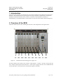
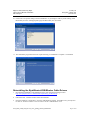
23-May-08
Physics and Astronomy Dept.
University of British Columbia
MCE Project
SC2_ELE_S580_520
Version 2.4
Getting Started with MCE
With Trouble-Shooting and Maintenance Guides
Revision History
Rev
.
1.0
1.1
2005
2006
EL
BB
Initial release
Added a section on how to trigger the MCE with Data Valid pulses. (Committed to
CVS, the equivalent version on the Physics server is v1.3. )
1.2
1.3
2006
2006
MA
BB
1.4
2006
BB
Added section 5.2, updated section 5.1 and 8.2.
Added a note about un-mating the MDM connectors, to prevent the mating screw
from seizing.
Moved all the non-hardware related topics to “MCE User’s Guide” and renamed
this file “MCE Hardware Manual.”
2.0
20070627
MA
Taken from MCE Hardware Manual 1.4. (This document was originally released as
MCE-Users’s Manual and then MCE Hardware Manual.)
added header and footer
updated table 2.1 and corrected heater/tes bias
updated power consumption in section 4.1
updated section 4.2 by mce_check script
2.1
20070629
TF
Deleted PSC references and converted to PSU with ACDCU. Updated pictures.
2.2
20071010
BB
Added a section on using Quartus to reprogram the MCE with new firmware.
2.3
20080110
MA
Updated TOC, header date and minor changes to section 4.2
2.4
20080522
MA
Updated fiber connection, cheater plug, section 3.2, 3.3, 4.2
Date
Who
Description of change
Table of Contents
GETTING STARTED WITH MCE ............................................................................................................. 1
REVISION HISTORY ................................................................................................................................. 1
TABLE OF CONTENTS ............................................................................................................................. 1
1.
INTRODUCTION .......................................................................................................................... 3
2.
OVERVIEW OF THE MCE ......................................................................................................... 3
3.
INSTALLING THE MCE ............................................................................................................. 6
4.
3.1
MOUNTING THE MCE ON THE CRYOSTAT ......................................................................................... 6
3.2
CONNECTING THE MCE TO THE RTL AND THE WINDOWS PCS ........................................................ 7
3.3
CONNECTING THE MCE TO THE AC-DC CONVERTER UNIT.............................................................. 8
3.4
CONNECTING THE MCE TO THE LINEAR POWER SUPPLY .................................................................. 9
VERIFYING THE MCE INSTALLATION ...............................................................................10
Physics and Astronomy Dept.
University of British Columbia
MCE Project
23-May-08
SC2_ELE_S580_520
Version 2.4
4.1
POWER-UP CHECK ...........................................................................................................................10
4.2
RUNNING SYSTEM-LEVEL TEST ON MCE ........................................................................................11
Starting the MCE Acquisition Software on PC ...............................................................................11
Issuing Commands to the MCE .......................................................................................................11
Running a Test Script ......................................................................................................................12
5
TROUBLESHOOTING THE MCE ............................................................................................14
5.1
LIST OF PROBABLE CAUSES OF ERROR ............................................................................................15
5.2
LIST OF KNOWN ISSUES ...................................................................................................................18
6
MAINTAINING THE MCE ........................................................................................................19
6.1
7
HARDWARE......................................................................................................................................19
6.1.1
Replacing a Backplane .....................................................................................................19
6.1.2
Replacing a Filter Box ......................................................................................................20
ADDITIONAL RESOURCES .....................................................................................................22
7.1
CONTACT INFORMATION ..................................................................................................................22
7.2
REFERENCES ....................................................................................................................................22
7.3
ACKNOWLEDGEMENTS.....................................................................................................................22
APPENDIX A: EXTERNAL LINEAR POWER SUPPLY MANUAL .................................................23
APPENDIX B: UPGRADING MCE FIRMWARE .................................................................................32
AUTOMATIC UPDATE USING A CDF FILE ...................................................................................................32
MANUAL UPDATE USING THE QUARTUS II PROGRAMMER .........................................................................34
UPDATING FIRMWARE USING THE RTL PC ................................................................................................38
APPENDIX C: INSTALLING QUARTUS SOFTWARE ......................................................................39
INSTALLING THE QUARTUS II PROGRAMMER .............................................................................................39
REINSTALLING THE BYTEBLASTER/USB-BLASTER CABLE DRIVERS .........................................................43
APPENDIX D: LIST OF ACRONYMS ...................................................................................................49
SC2_ELE_S580_520_Rev2.4_mce_getting_started_manual.doc
Page 2 of 49
23-May-08
Physics and Astronomy Dept.
University of British Columbia
MCE Project
SC2_ELE_S580_520
Version 2.4
1. Introduction
The purpose of this manual is to familiarize the user with the installation of the Multi-Channel Electronics
hardware. This manual presents a logical progression of steps required to setup the MCE, starting from
installation of the MCE subrack on the cryostat, to verification of the installation, and finally to
troubleshooting. The intended audience of this manual is an operator with minimal technical background.
2. Overview of the MCE
Each MCE subrack has ten slots containing the electronics cards designated as in the figure below.
AC
Figure 2.1
BC1
BC2
BC3
RC1
RC2
RC3
RC4
CC
PSU
MCE subrack with switching power supply card.
The Power Supply Unit connects to the ACDCU which supplies +/-150DC. The PSU converts this into
lower voltages required by the MCE electronics. A linear power supply feed card is also available but this
card only provides a connection for the external linear supplies to the MCE.
SC2_ELE_S580_520_Rev2.4_mce_getting_started_manual.doc
Page 3 of 49
23-May-08
Physics and Astronomy Dept.
University of British Columbia
MCE Project
AC
Figure 2.2
BC1
BC2
SC2_ELE_S580_520
Version 2.4
BC3
RC1
RC2
RC3
RC4
CC
PSU
MCE subrack with external-linear power supply card.
The address card, bias cards and readout cards process the signals to/from the cryogenic imaging subarrays. The clock card coordinates the signal-processing cards and provides the interface to the RTL PC.
SC2_ELE_S580_520_Rev2.4_mce_getting_started_manual.doc
Page 4 of 49
23-May-08
Physics and Astronomy Dept.
University of British Columbia
MCE Project
MDM 5
Figure 2.3
MDM 4
SC2_ELE_S580_520
Version 2.4
MDM 3
MDM 2
MDM 1
MCE subrack, rear view with MDM connector numbering indicated.
Connections from the signal-processing cards to the cryogenic arrays are accomplished through five MDM
connectors as designated in the Figure 2.3 above.
The signal-processing cards are connected to the MDM connectors as follows:
MDM 5
RC4 S1_FB[31:24]
SSA_SIG[31:24]
BC1 SSA_FB[31:24]
MDM 4
RC3 S1_FB[23:16]
SSA_SIG[23:16]
BC1 SSA_FB[23:16]
BC2 S2_FB[31:24]
BC2 S2_FB[23:16]
BC3 S2_Bias[31:24]
BC3 S2_Bias[23:16]
Table 2.1
MDM 3
RC2 S1_FB[15:8]
SSA_SIG[15:8]
BC1 SSA_FB[15:8]
BC2 Detector Bias
BC2 S2_FB[15:8]
MDM 2
RC1 S1_FB[7:0]
SSA_SIG[7:0]
BC1 SSA_FB[7:0]
BC3 S2_Bias[15:8]
BC1 Heater
BC3 S2_Bias[7:0]
BC2 S2_FB[7:0]
MDM 1
AC all signals
S1_Bias [41:0]
MDM connector signals
Production subracks will have no screens on the top and bottom, while prototype subracks will have a top
cover equipped with three fans and four support legs to facilitate airflow.
SC2_ELE_S580_520_Rev2.4_mce_getting_started_manual.doc
Page 5 of 49
Physics and Astronomy Dept.
University of British Columbia
MCE Project
23-May-08
SC2_ELE_S580_520
Version 2.4
The operation of the MCE is coordinated by the RTL PC. The RTL PC software will refer to the cards by
their designations from Figure 2.1. Please refer to the RTL PC software documentation for its features, setup, and operation [1].
3. Installing the MCE
This section describes how to complete the mechanical and electrical installation of the MCE.
3.1
Mounting the MCE on the Cryostat
Parts and Tools Required:
• 8 x M6x16 mm hex head cap screws
• 1 x 5mm ball driver
• 1 x Torque wrench
• 1 x 3mm hex driver bit for torque wrench
Instructions:
1. Prior to mounting the subrack check that the five 100-pin MDM connectors are retracted so there
is no interference when the subrack is mounted. The no interference position of these five
connectors is when the connector is not extended past the mounting surface of the subrack. We
also recommend that you test the connections to the MDM connectors on the cryostat wall before
mounting the MCE.
2.
Have the M6 screws within easy reach. Align the subrack locator pins with the corresponding
holes on the cryostat wall. Gently press the subrack into position. Install M6x16mm screws (8
pieces) and tighten. Figure 3.1 shows the locations of the mounting holes. Note that the other
four mounting holes are located on the opposite side.
Figure 3.1
3.
Fully-populated subrack with mounting holes highlighted.
Mate the cryostat connectors by turning the mating screws clockwise. The mating screws are
located on the front of the MCE, near the top edge. Use the torque wrench to torque the screws to
5 inch-pounds (56.49 Newton-centimetres). *Important: when dismounting the subrack, be sure
to retract the MDM connectors first. Four counter-clockwise turns of the mating screws are
sufficient to un-mate the MDM connectors entirely. If you do more than 4 turns, the mating screw
may bottom out and seize in the MDM-connector box’s tapped bore.
SC2_ELE_S580_520_Rev2.4_mce_getting_started_manual.doc
Page 6 of 49
Physics and Astronomy Dept.
University of British Columbia
MCE Project
3.2
23-May-08
SC2_ELE_S580_520
Version 2.4
Connecting the MCE to the PCs
Parts and Tools Required:
• 1 x duplex fibre-optic cable for connecting the MCE to the data-acquisition PC.
• A PC with a PCI Arc-64 card that has data-acquisition software installed.
• (optional) 1x duplex fibre optic cable for connecting the MCE to the Sync box
• (optional) 1 x Altera ByteBlasterMV or USB-Blaster cable
• (optional) 1 x parallel port or USB extension cable (if needed)
• (optional) A Windows PC with Altera Quartus Software installed.
Instructions:
1. Inspect the fibre-optic cable for any damage such as kinks in the fibre, loose connectors, or
damage in the cable jacket. If there appears to be any damage, replace the cable. Note that as an
industry standard, fibres are marked with “A” at one end and “B” at the other end , e.g. RX at one
end and TX at the other end. Sometimes they may be color coded.
2.
Connect the PC and the MCE with a pair of fibres. On the PC side, the fibre is connect to the
connectors on the PCI card in the back of the PC. On the MCE side, the fibre is connected to the
connectors labelled as RX-in and TX-out.
The red LED being “ON” on the clock card of the MCE indicates lack of signal either due to
cables being swapped or PC being off.
The red LED being “ON” on the back of the PC indicates lack of signal either due to cables being
swapped or the MCE being off.
Note that the connectors are keyed. If it does not fit, rotate the connector until it mates. Also note
that the connectors are spring-loaded and must be stretched and rotated clockwise in order to lock
the connector. Repeat process to connect the other end of the fibre to the SDSU card.
3.
Connect the MCE to the Sync Box (not shown in Figure 3.2). Connect one end of the fibre to one
of the connectors labelled as mce0 to mce7 in the back of the Sync box. Connect the other end to
the connector labelled as Sync-in on the MCE. When the Sync box is connected and on, the
yellow LED on the MCE goes off.
4.
Connect the 2x5-pin female header on the ByteBlasterMV or USB-Blaster cable to the 2x5-pin
male header on the clock card.
Note: The connector is keyed. If it does not fit, do not force it! Calmly rotate the connector π
radians and try again.
5.
If you are using a ByteBlasterMV cable, connect the 25-pin male connector to the parallel port of
the Windows PC. Use the parallel port extension cable if necessary. If you are using a USBBlaster cable, connect the A (rectangular) end of the USB cable to the PC and the B (square) end
to the receptacle on the USB-Blaster.
SC2_ELE_S580_520_Rev2.4_mce_getting_started_manual.doc
Page 7 of 49
23-May-08
Physics and Astronomy Dept.
University of British Columbia
MCE Project
SC2_ELE_S580_520
Version 2.4
3
2
4
Figure 3.2 Connections to the Data Acquisition and Windows PCs. (Note: Only one of ByteBlaster
or USB-Blaster should be used.)
3.3
Connecting the MCE to the AC-DC Converter Unit
Parts Required:
• 1 x ACDCCU power supply cable SC2-ELE-S580-170
• 1 x ACDCCU Cheater Plug SC2-ELE_S580-106 (replaces Sync Box) (Fig. 3.3)
• 1 x Synchronizer Box SC2-ELE-S589-101 (optional)
• 1 x Synchronizer Box Cable SC2-ELE-S580-171 (optional)
This method of powering the MCE uses the AC-DC Converter Unit. AC-DC Converter Units are designed
to provide power to a pair of MCE subracks using 1 cable for each MCE subrack. A single channel ACDC Converter Unit is also available for lab use to power a single MCE subrack. The AC-DC Converter
Unit must either be connected to a Synchronizer Box or have a dummy plug installed in the control input
connector.
Instructions:
1. Connect the power cable from the wall outlet to the ACDC Converter Unit.
2.
Connect the power supply cable between the MCE and the ACDCU. Note 2 pins are short and
mate last and disconnect first. This is a safety feature to ensure that there is no voltage on the
cable when the voltage pins are disconnected.
3.
Connect the “cheater plug” to the control input connector if you are going to turn the ACDCU on
and off manually.
If you want to remotely turn on/off the ACDCU through the Sync Box, then use the Sync-Box-toACDCU control cable to connect the ACDCU to one of the 8 ACDCU0 to ACDCU7 connectors
in the back of the Synchronizer Box.
4.
Connect the fan power supply cable from the external power supply to the fan power connector
located on the top panel of the MCE.
SC2_ELE_S580_520_Rev2.4_mce_getting_started_manual.doc
Page 8 of 49
23-May-08
Physics and Astronomy Dept.
University of British Columbia
MCE Project
SC2_ELE_S580_520
Version 2.4
Figure 3.3 Cheater Plug for ACDCU
3.4
Connecting the MCE to the Linear Power Supply
Parts Required:
• 2 x DC power supply cable
• 1 x fan power supply cable
• 1 x power cable
Instructions:
1. Connect the power cable from the wall outlet to the external power supply.
2.
Connect both DC power supply cables from the external power supply to the power supply card in
the MCE.
3.
Connect the fan power supply cable from the external power supply to the fan power connector
located on the top panel of the MCE.
3
1
2
Figure 3.4
Power connections to external linear power supply. (Note: PC connections not shown.)
SC2_ELE_S580_520_Rev2.4_mce_getting_started_manual.doc
Page 9 of 49
23-May-08
Physics and Astronomy Dept.
University of British Columbia
MCE Project
SC2_ELE_S580_520
Version 2.4
4. Verifying the MCE Installation
This section describes how to verify that the MCE has been set-up correctly, that the instrument firmware
has been automatically loaded, and that the MCE is functioning normally.
4.1
Power-Up Check
MCEs are fully tested at the factory before shipping. These tests include continuity checks of the MDM
connector signals, and functionality of all the cards with an RTL PC. We recommend that the connections
to the MDM connectors on the cryostat wall be pre-tested before installing the MCE.
Once the MCE is installed, follow this procedure to verify that the MCE was received and installed in good
order:
1.
If you are using the ACDCCU and PSU, turn on the ACDCCU and verify that the green LED on the
PSU is illuminated.
If you are using individual external linear power supplies, turn on the supplies in the following order:
+4.5VD, +5.0VD, +6.7VA, -6.7VA, +12.0VA, +2.7VD. The most important feature of this sequence
is that the +2.7VD (FPGA Core Voltage) is turned on last, otherwise the FPGAs may not configure
properly.
With a fully populated subrack (with all cards present), you can expect the following power
consumption:
Supply Voltage (V) Power Consumtion (Watts)
+5V
+2.7V
+4.5V
12.0VA
+6.7VA
-6.7VA
0
12.5
6.8
0.8
90
9
Table 4.1 MCE Power Consumption
2.
Immediately check to make sure that the fans on the top cover are running, if your MCE is soequipped. If not, turn off the power (ACDCCU, or the external power rack toggle switches in any
order although right to left is preferred) and check the fan-power connections.
3.
If you should see black smoke emanating from the MCE, immediately switch off the power supply.
This indicates that a component has shorted and the resulting high current has started to melt the IC
packaging. If, on the other hand, you see white smoke, do not be alarmed as this is usually dust
trapped in the MCE that was expelled by the fans.
4.
When you first power on the MCE, a series of red LEDs on each card are on, after a few seconds, the
red LEDs go off and green LEDs are turned on indicating that firmware is loaded to all FPGAs.
5.
The MCE may now be tested through the RTL PC. Or, it may be turned off by shutting off the
ACDCCU, or shutting down the external power rack toggle switches in any order, although a right-toleft shutdown sequence is preferred.
Should the mating of the MDM connectors be in question, the instrumentation bus tester may be used in
each signal-processing card slot to verify connectivity to the subarrays. Please take care and electrostatic
discharge precautions whilst handling the cards, and refer to the IBT manual for instructions [2].
SC2_ELE_S580_520_Rev2.4_mce_getting_started_manual.doc
Page 10 of 49
Physics and Astronomy Dept.
University of British Columbia
MCE Project
4.2
23-May-08
SC2_ELE_S580_520
Version 2.4
Running System-Level Test on MCE
Now you can control the MCE through the PC by issuing commands and running test scripts to evaluate the
health of your MCE.
Starting the MCE Acquisition Software on PC
Be sure that the MCE and the acquisition PC are linked with a duplex fibre-optic cable. Power on the MCE
and if needed configure the MCE with the correct firmware (see Appendix B: “Upgrading MCE
Firmware”).
The MCE is controlled via commands issued through the acquisition software running on the PC. Please
refer to [1] and [2] for detailed descriptions of the communications protocol and list of commands. The
following section assumes MAS acquisition software is installed on your PC:
Log on to the PC as “mce”
In order to create a data directory for today’s tests, in a terminal window type:
>set_directory
Now there is a directory in /data/cryo/current_data where the test results for today will be stored.
Issuing Commands to the MCE
The following section assumes MAS acquistion software is installed on your PC. For information about
MAS, see the wiki. For a list of MCE refer to “MCE Command Description” on MCE Command
Description.
You may read and write different parameters of the MCE. To read the offset value of a readout card, type:
>mce_cmd –x rb rc3 offset
where:
mce_cmd
-x
rb
rc3
offset
is the name of the software utility that executes the command
execute the remainder of the line as an MCE command.
stands for read
is the target card that the command is issued for
is the name of the parameter
You can find out more about mce_cmd by typing:
>mce_cmd –h
To modify the row length value:
>mce_cmd –x wb sys row_len 128
Another way to issue commands to MCE is to make a batch file and include a list of commands and then
execute the batch file by calling mcebatchgo. This batch file has to be under das/configfiles directory.
For example, you may create a batch file called “temp.bat” that contains the following commands:
rb rc3 offset
wb sys row_len 64
To run the batch file, type:
>mce_cmd –f temp.bat
Note: The collection of scripts located in $MAS_SCRIPT directory are designed to control the MCE and
facilitate the basic operations of MCE. A brief description for each script is also provided in the wiki.
SC2_ELE_S580_520_Rev2.4_mce_getting_started_manual.doc
Page 11 of 49
23-May-08
Physics and Astronomy Dept.
University of British Columbia
MCE Project
SC2_ELE_S580_520
Version 2.4
Running a Test Script
You may now proceed to verify the overall health of your MCE by running a test script. This test script
checks whether the communication link between the RTL PC and the MCE is reliable and that the MCE
firmware is operational. The test is interactive and goes through following steps:
•
•
•
•
•
•
toggles the faceplate LEDs.
Records firmware revisions of all cards
Records temperatures of all cards
Records electronic Ids of all cards
Records voltage/current draws
acquires several data frames and verifies them.
Run the test script by typing the following at the command prompt:
>mce_check
The results are saved in filename
/data/cryo/current_data
in $MAS_DATA directory which is typically set to
mandana@mce-act-a2:~/mce_script/trunk/test_suite$./mce_check
./mce_check run under MAS on Thu May 22 13:20:32 PDT 2008
watch the LEDs flash
ac fw_rev 0x2000005
bc1 fw_rev 0x1040001
bc2 fw_rev 0x1040001
bc3 fw_rev 0x1040001
rc1 fw_rev 0x4000006
rc2 fw_rev 0x4000006
rc3 fw_rev 0x4000006
rc4 fw_rev 0x4000006
cc fw_rev 0x4000009
ac fpga_temp 14
bc1 fpga_temp 25
bc2 fpga_temp 25
bc3 fpga_temp 28
rc1 fpga_temp 32
rc2 fpga_temp 34
rc3 fpga_temp 33
rc4 fpga_temp 33
cc fpga_temp 76
ac card_temp 24
bc1 card_temp 24
bc2 card_temp 24
bc3 card_temp 24
rc1 card_temp 28
rc2 card_temp 28
rc3 card_temp 28
rc4 card_temp 26
cc card_temp 24
ac card_id 12002161
bc1 card_id 17479857
bc2 card_id 17472657
bc3 card_id 17505530
SC2_ELE_S580_520_Rev2.4_mce_getting_started_manual.doc
Page 12 of 49
Physics and Astronomy Dept.
University of British Columbia
MCE Project
23-May-08
SC2_ELE_S580_520
Version 2.4
rc1 card_id 17497557
rc2 card_id 17499096
rc3 card_id 17496123
rc4 card_id 17512731
cc card_id 9664016
ac slot_id 0
bc1 slot_id 1
bc2 slot_id 2
bc3 slot_id 3
rc1 slot_id 4
rc2 slot_id 5
rc3 slot_id 6
rc4 slot_id 7
cc slot_id 8
**************************
ac card_type 0
bc1 card_type 1
bc2 card_type 1
bc3 card_type 1
rc1 card_type 2
rc2 card_type 2
rc3 card_type 2
rc4 card_type 2
cc card_type 3
**************************
card_id
00936433
PSUC firmware version
3.2
TEMP1 (PSUC)
32 C
TEMP2 (PSU)
32 C
TEMP3 (HS)
35 C
V_VCORE
3425 units
( 3.43V)
Nominal 3.00
V_VLVD
3196 units
( 4.81V)
Nominal 4.50
V_VAH
2997 units
(10.04V)
Nominal 10.00
V_VA+
3029 units
( 6.28V)
Nominal 6.20
V_VA3187 units
( 6.62V)
Nominal 6.20
I_VCORE
739 units
( 3.85A)
Nominal 13.00
I_VLVD
893 units
( 1.43A)
Nominal 4.00
I_VAH
1325 units
( 0.08A)
Nominal 0.15
I_VA+
2393 units
(14.38A)
Nominal 15.00
I_VA1576 units
( 1.26A)
Nominal 2.00
This is mce_cmd version MAS/act/218M
Line
0 : ok
Processed 0 lines, exiting.
RUNFILE_NAME=/data/cryo/current_data//.tmp.data.run
FRAME_BASENAME=/data/cryo/current_data//.tmp.data
MCE information collected and simple data acquisition test Passed!
SC2_ELE_S580_520_Rev2.4_mce_getting_started_manual.doc
Page 13 of 49
SC2_ELE_S580_520_Rev2.4_mce_getting_started_manual.doc
Page 14 of 49
“Error – MCE is still in an application”
10 11 12 13 14 15 16 17 18 19 20 21 22 23 24 25 26 27 28
“Error parsing XML file…failed to call mcexml_readXML”
9
“Failed to locate parameter…failed to call mcexml_translate”
8
“Timeout waiting for MCE/SDSU…”
“Device chain in chain descriptor file does not match
physical device chain…”
RTL Error Messages
“Programming hardware cable not detected.”
“Can’t configure device. Expected JTAG ID code…but
found JTAG ID code…”
“Can’t access JTAG chain.”
7
“Conf_done failed to go high.”
6
“Unable to scan device chain.”
Quartus Error Messages
MCE does not mate easily to cryostat mounting plate.
Card cannot be fully inserted.
5
Data file contains unexpected or invalid data.
4
Data file is empty.
3
MCE appears to execute a command, RTL reports timeout.
2
Power supply makes a hissing noise.
The cards’ green and yellow LEDs do not all illuminate on
power-up.
MCE front panels are hot to the touch.
1
Probable Cause of Error (see below)
5
The PSU front panel LED is not on.
Symptom
Physics and Astronomy Dept.
University of British Columbia
MCE Project
23-May-08
SC2_ELE_S580_520
Version 2.4
Troubleshooting the MCE
Physics and Astronomy Dept.
University of British Columbia
MCE Project
5.1
List of Probable Causes of Error
1
Filter boxes not fully retracted
23-May-08
SC2_ELE_S580_520
Version 2.4
The brass RF filter boxes must be fully retracted using the hex-socket drives on the front panel of the
subrack before mating to the cryostat mounting plate. Failure to do so will make it almost impossible to
mate the subrack to the cryostat, or even cause severe damage to the MDM connectors.
2
Cryostat mounting plate is faulty
The tolerance for the mounting plate to subrack mechanics is about 0.25mm. If the mating parts have
incurred any damage or distortion, mating will be difficult and potentially damaging to the MDM
connectors. Carefully inspect the mechanics and contact the UBC Physics and Astronomy SCUBA-2 team
if you have any doubts about the integrity of these parts.
3
Card has fallen off the guide rails
The subrack has been fitted with card-guide stiffening bars to reduce the chances of a card slipping out of
the guide rails; however, it can still happen. Under no circumstances force the card if it does not slide
smoothly into the card slot. It may be interfering with chassis structures or with the adjacent card.
Carefully remove the card and inspect the card guides and backplane connectors for the card slot before
reattempting to insert the card. See also probable cause #4, below.
4
Ejector latches closed while inserting card
During the final 5mm of card insertion, the open ejector latches will normally engage the subrack.
However, if the latches have been closed prior to engaging, they will bind against the subrack and prevent
final mating of the card. Retract the card slightly and ensure the latches are open, then the card should slide
smoothly until the latches engage--then close the latches to mate the backplane connectors. If there is any
resistance, do not force the card, as doing so could cause severe damage to the MCE. See also probable
cause #3, above.
5
MCE not powered on
Check that either a cheater plug is installed at the Control Input Connector of the ACDCCU or a
Synchronizer Box is connected and powered on.
6
The power supply is not plugged in
Check to ensure that all the switches of the linear power rack are in the “on” position. If you are using the
ACDCCU and PSU ensure that the power cable is fully mated. Check that the Cable OK and High Voltage
On LED are illuminated on the ACDCCU.
7
The linear power supply or power supply unit is faulty
If the MCE does not receive power despite the cables being attached and the power supply being switched
on, there may be open fuses in the power supply. Refer to the power supply manual and check the fuses,
but do not replace the fuses until you have determined the cause for the overload. Under no circumstances
replace a fuse with one of a higher rating or slower response characteristic.
In the event that the fuses are alright, then the power supply may have failed internally. Contact the UBC
Physics and Astronomy SCUBA-2 team in this case.
8
Fan bearings are failing
Ventilation fans may begin to make hissing, groaning or grinding sounds as their bearings dry out and
begin to fail. Try to ascertain which fan is making the noise, but be careful when placing your ear close to
SC2_ELE_S580_520_Rev2.4_mce_getting_started_manual.doc
Page 15 of 49
Physics and Astronomy Dept.
University of British Columbia
MCE Project
23-May-08
SC2_ELE_S580_520
Version 2.4
it as the noise may really be from a snake (see probable cause #8, below). Power off the power supply, and
place a pen or pencil in the suspect fan to prevent it from turning, and then turn on the power supply
momentarily. If the noise is no longer present, the stopped fan requires servicing or replacement. Do not
leave the power supply on for more than 30 seconds with a fan stopped. If a fan has failed entirely (i.e. it
does not turn at all) then continuing to operate the power supply could result in catastrophic failure due to
overheating – do not run a power supply under such a condition.
9
Removed
10
Power supply turned on in wrong sequence
The cards' FPGAs will automatically configure only if the LOGIC voltage (+4V5d) is switched on before
the CORE voltage (+2V5d). Make sure you activate the linear power rack's toggle switches in the correct
sequence, as indicated on its front panel. If you are using the PSC and 24V power unit, the sequencing is
automatic and this diagnosis does not apply to your problem; in this case, see probable cause #11, below.
11
Instrumentation firmware not loaded into cards
The MCE cards were pre-loaded with instrumentation firmware and should automatically configure and
illuminate their red, yellow and green front-panel lamps a few seconds after power-up. Should this not
occur, the affected card(s) may have been reprogrammed with different firmware. Follow the instructions
in this manual for programming the configuration devices to restore the instrumentation firmware.
12
Subrack fans are not powered
The prototype subrack is fitted with six ventilation fans, and these are essential for the proper operation and
survival of the MCE. Check that these fans are powered through the grey cable (see the Installation
section) and that they are moving air. If not, immediately shut off the power supply to the MCE and
remedy the non-operational fan(s) before continuing to use the system. See also probable cause #13,
below.
13
Restricted airflow through subrack
The prototype subrack is fitted with legs to ensure adequate airflow in case it is placed on a flat surface. A
production subrack only has top and bottom screens, and no fans or legs. Adequate airflow must be
provided or the MCE will overheat and be severely damaged. If the MCE is hotter than usually, then check
the airflow immediately.
14
Readout cards normally generate large quantities of heat
The metal surfaces of the subrack will be warm under normal operation. The front panels of the readout
cards will be almost uncomfortable to touch for more than five seconds at a time – this is normal.
However, no part of the MCE should be hot enough to cause a reflex upon contact.
15
ByteBlaster/USB-Blaster is not connected
Ensure that both the computer end (parallel or USB cable) and subrack end (ribbon cable) end of the Altera
programming adapter (“ByteBlaster” or “USB-Blaster”) are connected. If in doubt, disconnect and
reconnect the cables.
16
Incorrect parallel or USB port settings
The PC you are using may have parameters in its BIOS or operating system that enable or disable, or set
special modes, for the parallel or USB port. Check these parameters for inappropriate values.
17
MCE JTAG chain has encountered an error
Occasionally, a bit error may occur in the JTAG chain. When this occurs, the MCE and/or Quartus
Programmer software may be left in a bad state, causing any or all of the error messages you are seeing. To
SC2_ELE_S580_520_Rev2.4_mce_getting_started_manual.doc
Page 16 of 49
Physics and Astronomy Dept.
University of British Columbia
MCE Project
23-May-08
SC2_ELE_S580_520
Version 2.4
clear this condition, shut off the MCE's power supply, disconnect the Altera programming adapter
(“ByteBlaster” or “USB-Blaster”), and close Quartus. Then, turn on the power supply, reconnect the
programming adapter and re-launch Quartus. Note that leaving the programming adapter connected could
prevent the error condition from being cleared, despite power-cycling the subrack and restarting Quartus.
18
Fibre-optic cable is disconnected or broken
Check to ensure that both fibre-optic cables are connected to the correct connectors and that they have not
been damaged. Note that a functional RTL-PC-to-MCE cable with a non-functional MCE-to-RTL-PC
cable can cause timeout errors that mimic software errors in some situations. (The MCE receives and
executes commands, but the RTL PC does not receive the responses.)
19
SDSU card DSP software is corrupted
The SDSU fibre-optic card in the RTL PC contains and executes software in its on-board DSP chip. Bugs
may exist which cause this software to become corrupted or crash. Should you suspect this to be the case,
you must completely power down the RTL PC by following the standard Linux shutdown procedure. Only
if the SDSU card is powered cycled will this condition be cleared.
20
Wrong filename was specified
Make sure you have specified the correct script, configuration or log file name. Note that the RTL PC
scripts may locate files in directories that may not be obvious to you. Refer to the MCE Command Manual
for information about expected script and directory names.
21
Connection problems to cryostat
“Bad” collected data may be due to connection problems at the MDM connectors, cold (internal cryostat)
connections or internal MCE connections. We fully tested the MCE subrack connections and have found
them to be highly reliable. If data collection has been previously successful and has become bad, it is more
likely that a connection problem has developed in the cold connections and MDM connectors than in the
MCE.
22
Incorrect bias values specified
Since bias values are specified, in many cases, on RTL command lines, it is easy to type incorrect
parameter values resulting in bias currents that are out of range for your subarray. Check your scripts and
command lines for typographical errors.
23
Power supply has browned out
Excessive heat in the subrack can cause the on-card voltage regulators to shut down. Additionally,
excessive heat can cause the linear power rack to brown out. If you are experiencing “bad” data after
running for a long period of time on a hot day, try shutting down the system and blowing cool air through
the subrack and linear power rack with external fans for 15 to 20 minutes, and recapturing your data.
24
Faulty readout card ADCs
The AD6644 analogue-to-digital converters used in the readout cards are known to exhibit anomalous
behaviour that we have not been able to explain yet. NIST noticed this, too, and replaced some ADCs in
the past. An ADC problem will affect the same subarray column in all your data, and may appear as noise
or badly distorted waveforms. Should you suspect an ADC failure, please contact the UBC Physics and
Astronomy SCUBA-2 team.
25
One or more cards' FPGAs have become corrupted
FPGAs are RAM-based devices and are subject to corruption under certain, rare, circumstances. Should
one card in the subrack become unresponsive (as reported the RTL PC software), try reconfiguring that one
card's FPGA using Quartus Programmer. Alternately, resetting the subrack (via the reset button on the
SC2_ELE_S580_520_Rev2.4_mce_getting_started_manual.doc
Page 17 of 49
Physics and Astronomy Dept.
University of British Columbia
MCE Project
23-May-08
SC2_ELE_S580_520
Version 2.4
subrack or by power-cycling the power supply) will clear the problem. Please keep a record of such lossof-configuration occurrences and report them to the UBC Physics and Astronomy SCUBA-2 team.
26
Invalid command was specified
Your script or command-line referred to an MCE command that is not defined in the mce.xml file you had
in-place when you started the DASDRAMA system. Please refer to the MCE Command Manual for
information on MCE command definitions.
27
mce.xml is corrupted
The DASDRAMA system could not understand the contents of your mce.xml file. You may have edited
this file and made a typographical error. The error message will indicate which line of the mce.xml file the
error is on. Correct the error and restart DASDRAMA. Please refer to the DAS manual for instructions on
how to do this.
28
DASDRAMA is corrupted
A software bug prevents DASDRAMA from exiting gracefully when an impatient user aborts a data return
command by pressing Control-C. Shut down the DASDRAMA process then restart it. Please refer to the
DAS manual for instructions on how to do this.
5.2
List of Known Issues
1
JTAG programming failures
Mostly during programming of a full subrack, Quartus Programmer will report a wrong silicon ID for a
device in the JTAG chain and a programming failure. Quartus is now in a bad state, and must be closed
and re-launched; Auto-Detect will work but programming reports Device Chain Busy unless Quartus is
restarted. Sometimes, the subrack is also left in a bad state and will need to be power-cycled with the
ByteBlaster unplugged from the Clock Card's front panel connector.
SC2_ELE_S580_520_Rev2.4_mce_getting_started_manual.doc
Page 18 of 49
Physics and Astronomy Dept.
University of British Columbia
MCE Project
6
23-May-08
SC2_ELE_S580_520
Version 2.4
Maintaining the MCE
The MCE is shipped with spare backplanes and filter boxes which can be used if the original parts are
defective or broken. Also, it may become necessary to start with a clean re-install of the Windows software
if it becomes corrupt. The procedures described below outline how to perform basic maintenance of the
MCE.
6.1
Hardware
This section outlines how to replace the backplane and the filter boxes.
6.1.1 Replacing a Backplane
The procedure for replacing either the instrument backplane or the bus backplane is basically the same.
However, extra work is required with the IB due to the Delphi flex connections.
Parts and Tools Required:
• 1 x Backplane PCB (instrument backplane or bus backplane)
• 1 x Torque wrench
• 1 x 1mm spacer bar
• 2 x PCB alignment plug-in card
Instructions:
1. Be sure that all cards are removed from the subrack.
2. (Applies to IB only) Remove the filter boxes and Delphi flex circuits connected to the IB.
3. Remove the back panel of the subrack. Place the subrack with the front panel on the work bench.
4. Remove the M2.5 x 8mm screws holding the backplane to the rails. Also remove the screws
(highlighted in yellow, below) connecting the backplane to the grounding bracket at the right hand
side.
5. Carefully remove the backplane taking care not to bend any connector pins.
6. Place the new backplane into the subrack. Be sure that the 1mm thick spacer bar (in red, below)
goes between the backplane and the rail. This spacer bar moves the backplane 1mm away from
the plug-in cards.
SC2_ELE_S580_520_Rev2.4_mce_getting_started_manual.doc
Page 19 of 49
Physics and Astronomy Dept.
University of British Columbia
MCE Project
23-May-08
SC2_ELE_S580_520
Version 2.4
7.
Reinstall all M2.5 x 8mm screws finger tight.
8.
Insert the address card into the AC slot (slot 0) and the clock card into the CC slot (slot 8). This
will align the backplane to the cards.
9.
Using a torque wrench set to 3 lb-in, tighten all screws. Do not over-tighten the screws as the
tapped aluminium rails only have 2mm of tap and are easily stripped. Remove the AC and the CC
from the subrack.
10. (Applies to IB only) Install the 5 Delphi Flex circuits and torque mounting screws to 8 lb-in. See
Section 7.1.2 for instructions on how to install the filter boxes.
6.1.2 Replacing a Filter Box
Parts and Tools Required:
• 1 x Filter box assembly
• 1 x Delphi Flex and hardware
• 1 x Torque wrench
• 1 x 3/32” hex driver bit for torque wrench
Instructions:
1. Remove the subrack’s top fan cover and rear panel.
2.
The Delphi flex connection consists of the flex PCB with gold dots on each end. Each end has a
two piece mounting fixture held together with two 4-40 x 0.375” cap screws. To assemble the
connection be sure that the gold dots on the flex are mating with the gold pads on the PCB.
3.
Install the instrument bus mounted Delphi connection first. Torque the mounting hardware to 8
lb-in.
4.
Install the filter box Delphi connection last. Push the flex so gold dots go on the correct side of the
filter box PCB as shown below:
SC2_ELE_S580_520_Rev2.4_mce_getting_started_manual.doc
Page 20 of 49
Physics and Astronomy Dept.
University of British Columbia
MCE Project
23-May-08
SC2_ELE_S580_520
Version 2.4
5.
Grasp assembly as shown below. The Delphi black tapped strip can also be grasped at the same
time. Hand tighten the two 4-40 cap screws.
6.
Torque the two 4-40 cap screws to 8 lb-in as shown.
7.
Repeat steps for remaining filter boxes. Release torque setting on wrench when completed.
SC2_ELE_S580_520_Rev2.4_mce_getting_started_manual.doc
Page 21 of 49
23-May-08
Physics and Astronomy Dept.
University of British Columbia
MCE Project
7
SC2_ELE_S580_520
Version 2.4
Additional Resources
If you are encountering problems with the Multi-Channel Electronics that are not addressed in this manual,
additional help is available through our offices listed below. Related documents are also available and can
be downloaded from the SCUBA–2 web site.
7.1
Contact Information
MCE web site:
http://www.phas.ubc.ca/~mce
Hardware / Firmware Engineering Team:
Department of Physics and Astronomy
#204 – 6224 Agricultural Road
Vancouver, BC
V6T 1Z1
Canada
7.2
Software Engineering Team:
UK ATC, Royal Observatory of Edinburgh
Blackford Hill
Edinburgh, Scotland
EH9 3HJ
United Kingdom
References
[1] SCUBA2-das-engineer-user-manual-V2.0.doc
[2] IBT manual
[3] “MCE Command Description”, SC2_ELE_S580_515_mce_command_description.pdf
7.3
Acknowledgements
Thanks to everyone who contributed, edited, critiqued, and otherwise helped me put this document
together:
Mandana Amiri, Bryce Burger, Tom Felton, Gar Fisher, Mark Halpern, William Hue,
Anthony Ko, Janos Molnar, Marcel Veronesi, and finally Bridget in the Main Office for
allowing me to borrow the department’s digital camera for extended periods of time.
SC2_ELE_S580_520_Rev2.4_mce_getting_started_manual.doc
Page 22 of 49
Physics and Astronomy Dept.
University of British Columbia
MCE Project
23-May-08
SC2_ELE_S580_520
Version 2.4
Appendix A: External Linear Power Supply Manual
CAUTION
DO NOT OPEN THE CABINET OR TAMPER WITH THE LOCKING BARS THAT ARE ON THE
FRONT OF THE KEPCO SUPPLIES.
DO NOT USE ANY FRONT PANEL TIP JACKS TO SUPPLY POWER TO EXTERNAL CIRCUITRY.
HOOK UP THE EXTERNAL FANS CABLE PRIOR TO POWERING UP THE SUBRACK.
ENSURE THAT THE AC POWER CORDS FOR THE KEPCO SUPPLIES ARE BOTH PLUGGED
INTO THE REAR PANEL.
ENSURE THAT THE DC POWER CORDS FROM THE REAR PANEL ARE FASTENED TO THE
KEPCO SUPPLIES.
A.1
Overview
The schematics of the power supply can be found on the following pages, in figures A.1 to A.5.
The pin out of both DC output power cables is identical. This means that the cables can be swapped
without any concern. The pin out of the Amphenol connectors on the rear panel is listed in figure A.6.
The output voltages are as follows. +2V5d, +4V5d, +5V0d, +6V7a, -6V7a, +15Va.
There are aluminum bars that lock the voltage and current adjustment on the Kepco supplies found on the
lower portion of the 8U high cabinet. Do NOT remove the bars or adjust the knobs. The voltage and
current levels on the Kepco supplies have been pre-set.
There are tip jacks on the front panel that allow the user to read the output voltages and currents of the
supply. It is important to ensure that the tip jacks are not used to supply power to any external circuitry.
The +2V5d and +6V7a supplies have panel meters for current monitoring and tip jacks for voltage
monitoring on the front panel. The +4V5d, +5V0d, -6V7a, +15Va have jacks that the user can measure
both voltage and current. The “COMMON” black tip jacks refer to the current and voltage tip jacks above
them. They are not common to each other, or any tip jacks in other columns.
Voltage measurement is done using a DVM connected to the “VOLTAGE” and “COMMON” jacks and is
read directly with no conversion factor.
Current is measured as a voltage read across the appropriate shunt resistor for the circuit in question. The
+4V5d and -6V7a power supply circuits express measured current values as 10mV/A. The +5V0d and
+15Va power supply circuits express measured current values as 100mV/A.
SC2_ELE_S580_520_Rev2.4_mce_getting_started_manual.doc
Page 23 of 49
Physics and Astronomy Dept.
University of British Columbia
MCE Project
Figure A.1
23-May-08
SC2_ELE_S580_520
Version 2.4
Power supply schematics. (1 of 5)
SC2_ELE_S580_520_Rev2.4_mce_getting_started_manual.doc
Page 24 of 49
Physics and Astronomy Dept.
University of British Columbia
MCE Project
Figure A.2
23-May-08
SC2_ELE_S580_520
Version 2.4
Power supply schematics. (2 of 5)
SC2_ELE_S580_520_Rev2.4_mce_getting_started_manual.doc
Page 25 of 49
Physics and Astronomy Dept.
University of British Columbia
MCE Project
Figure A.3
23-May-08
SC2_ELE_S580_520
Version 2.4
Power supply schematics. (3 of 5)
SC2_ELE_S580_520_Rev2.4_mce_getting_started_manual.doc
Page 26 of 49
Physics and Astronomy Dept.
University of British Columbia
MCE Project
Figure A.4
23-May-08
SC2_ELE_S580_520
Version 2.4
Power supply schematics. (4 of 5)
SC2_ELE_S580_520_Rev2.4_mce_getting_started_manual.doc
Page 27 of 49
Physics and Astronomy Dept.
University of British Columbia
MCE Project
Figure A.5
23-May-08
SC2_ELE_S580_520
Version 2.4
Power supply schematics. (5 of 5)
SC2_ELE_S580_520_Rev2.4_mce_getting_started_manual.doc
Page 28 of 49
23-May-08
Physics and Astronomy Dept.
University of British Columbia
MCE Project
Figure A.6
SC2_ELE_S580_520
Version 2.4
Amphenol connector pinout.
The upper removable shelf of the power supply is populated with the following Power-One linear power
supplies:
Part Number
HC5-6/OVP
HA5-1.5/OVP-A
HB12-1.7-A
HAD15-0.4-A
HAD12-.4-A
Table A.1
Fuse
F1
F2
F3
F4
F5
F6
Table A.2
Function
4V5d power
5V0d power
–6V7a power
+15Va power
24V external fan
Output Current
6A
1.5A
1.7A
0.4A
N/A
Upper shelf components.
Type
10 A, SLO BLOW
1.0 A, SLO BLOW
0.5 A, SLO BLOW
0.5 A, SLO BLOW
0.5 A, SLO BLOW
0.5 A, SLO BLOW
Upper shelf fuse specifications.
SC2_ELE_S580_520_Rev2.4_mce_getting_started_manual.doc
Page 29 of 49
23-May-08
Physics and Astronomy Dept.
University of British Columbia
MCE Project
SC2_ELE_S580_520
Version 2.4
The lower deck of the power supply cabinet has two pre-set Kepco JQE series power supplies. The front
panel adjustments have been locked with aluminum bars. Do not remove these or unscrew the set screws.
Part Number
JQE6-22M
JQE15-25M
Table A.3
Function
+2V5d power
+6V7d power
Output Current
22A
25A
Lower deck components.
The listed current output values are from the manufacturer of the modules within the cabinet and do not
take into account parasitic losses from cables and interconnects.
For further details on the power supply modules that make up the power supply, refer to the manufacturer’s
websites, http://www.power-one.com and http://www.kepcopower.com.
For JQE6-22M see Kepco Instruction Manual Doc. # M576220 Rev. 19 (included).
For JQE15-25M see Kepco Instruction Manual Doc. # M607540 Rev. 24 (included).
A.2
Switch On & Switch Off Sequence
Switching sequence for ON:
Switching sequence for OFF:
A.3
MAIN, LOGIC, CORE, ANALOG
ANALOG, CORE, LOGIC, MAIN
(switch on from Left to Right)
(switch off from Right to Left).
Removing the Upper Shelf
1.
2.
3.
Turn off the power supply. See above for switch off sequence.
Remove all external connections to the power supply.
At the rear of the power supply:
a. Disconnect the DC power connections from the two Kepco’s
b. Unplug the AC line cords from the upper shelf rear panel
c. Remove the inner 4 x 10-32 PHI screws that hold the rear panel to the inverted U-shaped
aluminum keeper plate
4.
At the front of the power supply:
a. Remove 4 x 10-32 PHI screws that fasten the grill to the front panel to the mounting rails.
b. Remove the grill components.
c. Remove the outer 4 x 10-32 PHI screws that fasten the front panel to the mounting rails.
d. Slowly pull out the upper shelf. Ensure the DC power connectors at the rear do not snag
on the perforations of the Kepcos’ cabinets.
SC2_ELE_S580_520_Rev2.4_mce_getting_started_manual.doc
Page 30 of 49
23-May-08
Physics and Astronomy Dept.
University of British Columbia
MCE Project
A.4
SC2_ELE_S580_520
Version 2.4
Installing the Upper Shelf
Installation of upper shelf is the reverse of removal.
A.5
Dimensions
The overall mechanical dimensions of the power supply, (excluding foldable handles), is:
height = 16” (40.6 cm)
weight = 139.5 lbs
depth = 24.5” (62.2 cm)
width = 21” (53.3 cm)
SC2_ELE_S580_520_Rev2.4_mce_getting_started_manual.doc
Page 31 of 49
Physics and Astronomy Dept.
University of British Columbia
MCE Project
23-May-08
SC2_ELE_S580_520
Version 2.4
Appendix B: Upgrading MCE Firmware
This section describes how to load firmware into the MCE. We currently support two methods of updating
firmware; both involve using the Quartus II Programmer software. A third method of updating firmware,
using the RTL PC, is not currently supported. With the Quartus Programmer, one can use a CDF file that
automatically selects each card’s firmware (recommended), or one can load the firmware manually by
individually choosing what firmware goes into each card. CDF files can be obtained from the UBC
firmware engineering team.
Automatic Update Using a CDF File
Note: In order to use a CDF file, your MCE subrack must be fully populated (all cards must be plugged
in). Otherwise, the programmer will report an error.
1.
Start the Quartus Programmer by selecting Start Altera Quartus II 4.2sp1 Programmer. If you
did not install into the “Altera” program folder, substitute the correct folder name above.
Verify that the correct programming hardware is selected. If “No Hardware” is displayed in the top
left-hand corner, click on Hardware Setup. Otherwise, proceed to Step 3.
2.
Double-click on “ByteBlaster” or “USB-Blaster” under “Available hardware items” to select the
programming hardware. If no such device is available, verify that the Altera ByteBlaster or Altera
USB-Blaster driver has been installed on the system. Click Close. You should now see “ByteBlaster”
or “USB-Blaster” in the top left-hand corner.
SC2_ELE_S580_520_Rev2.4_mce_getting_started_manual.doc
Page 32 of 49
Physics and Astronomy Dept.
University of British Columbia
MCE Project
23-May-08
SC2_ELE_S580_520
Version 2.4
3.
Click on File Open… and browse to the directory containing the CDF file. Select the CDF file and
click Open.
4.
Click Start to begin the firmware update process.
5.
Upon successful completion, the status messages at the bottom will appear in green at the bottom of
the window. If there is a problem, error messages will be displayed in red. Refer to the
troubleshooting guide for assistance.
SC2_ELE_S580_520_Rev2.4_mce_getting_started_manual.doc
Page 33 of 49
Physics and Astronomy Dept.
University of British Columbia
MCE Project
23-May-08
SC2_ELE_S580_520
Version 2.4
Manual Update Using the Quartus II Programmer
Note: In order to program the clock card’s Factory configuration device, put the clock card on an extender
card and connect the programming cable to the JTAG header (header P2).
1.
Start the Quartus Programmer by selecting Start Altera Quartus II 4.2sp1 Programmer. If you
did not install into the “Altera” program folder, substitute the correct folder name above.
Verify that the correct programming hardware is selected. If “No Hardware” is displayed in the top
left-hand corner, click on Hardware Setup. Otherwise, proceed to Step 3.
SC2_ELE_S580_520_Rev2.4_mce_getting_started_manual.doc
Page 34 of 49
Physics and Astronomy Dept.
University of British Columbia
MCE Project
23-May-08
SC2_ELE_S580_520
Version 2.4
2.
Double-click on “ByteBlaster” or “USB-Blaster” under “Available hardware items” to select the
programming hardware. If no such device is available, verify that the Altera ByteBlaster or Altera
USB-Blaster driver has been installed on the system. Click Close. You should now see “ByteBlaster”
or “USB-Blaster” in the top left-hand corner.
3.
Click Auto Detect. In the list of devices that appears, each card in the MCE appears as a group of two
devices, consisting of one “EPC16/4/8” configuration device and one “EP1Sxx” FPGA device.
Furthermore, each card is listed in order from MCE slot 1 (address card) at the top of the list to MCE
slot 9 (clock card) at the bottom.
SC2_ELE_S580_520_Rev2.4_mce_getting_started_manual.doc
Page 35 of 49
Physics and Astronomy Dept.
University of British Columbia
MCE Project
4.
23-May-08
SC2_ELE_S580_520
Version 2.4
If you are programming the FPGAs, double click on the “<none>” beside each EP1Sxx device that you
wish to program and select the appropriate programming file. FPGA programming files have file
extension .sof.
If you are programming the configuration devices, double click on the “<none>” beside each
EPC16/4/8 device that you wish to program and select the appropriate programming file.
Configuration device programming files have file extension .pof
5.
Put a checkmark in each box under “Program/Configure” corresponding to the FPGA or configuration
device that you selected in Step 4.
SC2_ELE_S580_520_Rev2.4_mce_getting_started_manual.doc
Page 36 of 49
Physics and Astronomy Dept.
University of British Columbia
MCE Project
23-May-08
SC2_ELE_S580_520
Version 2.4
6.
If you are programming configuration devices, you will need to tell the Quartus Programmer to trigger
an automatic reconfiguration of the FPGAs after the configuration devices have been loaded. To
enable this, click on Options Initiate Configuration After Programming.
7.
Click Start to begin the firmware update process.
SC2_ELE_S580_520_Rev2.4_mce_getting_started_manual.doc
Page 37 of 49
Physics and Astronomy Dept.
University of British Columbia
MCE Project
8.
23-May-08
SC2_ELE_S580_520
Version 2.4
Upon successful completion, the status messages at the bottom will appear in green at the bottom of
the window. If there is a problem, error messages will be displayed in red. Refer to the
troubleshooting guide for assistance.
Updating Firmware Using the RTL PC
Updating the firmware using the RTL PC via the fibre-optic link is not supported as of yet. This document
will be updated when this functionality comes online.
SC2_ELE_S580_520_Rev2.4_mce_getting_started_manual.doc
Page 38 of 49
Physics and Astronomy Dept.
University of British Columbia
MCE Project
23-May-08
SC2_ELE_S580_520
Version 2.4
Appendix C: Installing Quartus Software
This section describes how to reinstall the software and drivers required for loading the MCE firmware.
Installing the Quartus II Programmer
1.
Uninstall the existing software by clicking on Start All Programs Altera Quartus II
Programmer and SignalTap Uninstall, Repair or Modify. Select Remove and click Next.
Note: If this does not work, try using the Add/Remove Programs wizard from the Windows Control
Panel. You can also attempt to reinstall the Programmer on top of the old installation without
removing it first.
2.
Click OK to remove the Quartus II Programmer from your system. When prompted, click Finish to
complete the uninstall.
3.
Download the Quartus II Programmer, version 4.2 SP1, from the following location:
http://www.physics.ubc.ca/~scuba2/sc2mce/system/sys_fw/quartus2programmer.exe
SC2_ELE_S580_520_Rev2.4_mce_getting_started_manual.doc
Page 39 of 49
Physics and Astronomy Dept.
University of British Columbia
MCE Project
23-May-08
SC2_ELE_S580_520
Version 2.4
4.
Double-click on the downloaded file to start the installation program. Click Next.
5.
Select “I accept the terms of the license agreement” then click Next.
SC2_ELE_S580_520_Rev2.4_mce_getting_started_manual.doc
Page 40 of 49
Physics and Astronomy Dept.
University of British Columbia
MCE Project
23-May-08
SC2_ELE_S580_520
Version 2.4
6.
Enter your information in the appropriate fields then click Next.
7.
Click Next if you agree to install the programmer in the indicated location. Otherwise, select a
different directory then click Next.
SC2_ELE_S580_520_Rev2.4_mce_getting_started_manual.doc
Page 41 of 49
Physics and Astronomy Dept.
University of British Columbia
MCE Project
23-May-08
SC2_ELE_S580_520
Version 2.4
8.
Click Next to install both the Programmer and SignalTap II.
9.
Click Next if you agree to the default program folder name. Otherwise, choose a different name then
click Next.
SC2_ELE_S580_520_Rev2.4_mce_getting_started_manual.doc
Page 42 of 49
Physics and Astronomy Dept.
University of British Columbia
MCE Project
23-May-08
SC2_ELE_S580_520
Version 2.4
10. Click Next to accept the settings and start installation. If you disagree with any of the settings, click
Back until you arrive at the appropriate page and then make your corrections.
11. The stand-alone programmer does not require licensing, so installation is complete. Click Finish.
Reinstalling the ByteBlaster/USB-Blaster Cable Drivers
1.
Download the ByteBlaster and USB-Blaster driver files from the following location:
http://www.physics.ubc.ca/~scuba2/sc2mce/system/sys_fw/drivers.zip
2.
Extract the files. Note the location of the extracted files.
3.
Open the Windows Control Panel. Open the Add Hardware Wizard. In Windows XP, you may have
to click on “Switch to Classic View” in order to see the “Add Hardware” icon.
SC2_ELE_S580_520_Rev2.4_mce_getting_started_manual.doc
Page 43 of 49
Physics and Astronomy Dept.
University of British Columbia
MCE Project
4.
23-May-08
SC2_ELE_S580_520
Version 2.4
Click Next.
SC2_ELE_S580_520_Rev2.4_mce_getting_started_manual.doc
Page 44 of 49
Physics and Astronomy Dept.
University of British Columbia
MCE Project
5.
Select “Yes, I have already connected the hardware” then click Next.
6.
Scroll down and select “Add a new hardware device” then click Next.
SC2_ELE_S580_520_Rev2.4_mce_getting_started_manual.doc
23-May-08
SC2_ELE_S580_520
Version 2.4
Page 45 of 49
Physics and Astronomy Dept.
University of British Columbia
MCE Project
23-May-08
SC2_ELE_S580_520
Version 2.4
7.
Select “Install the hardware that I manually select from a list (Advanced)” then click Next.
8.
Scroll down and select “Sound, video and game controllers” then click Next.
9.
Click on Have Disk.
SC2_ELE_S580_520_Rev2.4_mce_getting_started_manual.doc
Page 46 of 49
Physics and Astronomy Dept.
University of British Columbia
MCE Project
23-May-08
SC2_ELE_S580_520
Version 2.4
10. Browse to the folders in which you extracted the drivers. If you are installing a ByteBlasterMV,
browse to the /byteblaster subdirectory. Otherwise, browse to the /usbblaster subdirectory. Click OK.
If a warning appears, click Continue Anyway.
11. Select Altera ByteBlaster or Altera USB-Blaster (depending on which one you are installing) then
click Next.
SC2_ELE_S580_520_Rev2.4_mce_getting_started_manual.doc
Page 47 of 49
Physics and Astronomy Dept.
University of British Columbia
MCE Project
23-May-08
SC2_ELE_S580_520
Version 2.4
12. Click Next to begin installation. If a warning appears, click Continue Anyway.
13. Click Finish. Reboot the PC to complete the installation.
SC2_ELE_S580_520_Rev2.4_mce_getting_started_manual.doc
Page 48 of 49
Physics and Astronomy Dept.
University of British Columbia
MCE Project
23-May-08
SC2_ELE_S580_520
Version 2.4
Appendix D: List of Acronyms
AC
Address Card
BB
Bus Backplane
BC
Bias Card
CC
Clock Card
CDF
Chain Descriptor File
IB
Instrument Bus (backplane)
IBT
Instrument Bus Tester
MCE
Multi-Channel Electronics
MDM
Micro-D Metal
PC
Personal Computer
PCB
Printed Circuit Board
PSC
Power Supply Card
RC
Readout Card
RTL
Real-Time Linux
SDSU
San Diego State University (refers to a PCI card in the RTL PC)
SC2_ELE_S580_520_Rev2.4_mce_getting_started_manual.doc
Page 49 of 49