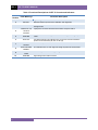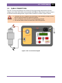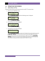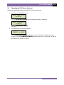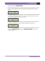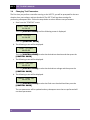
1
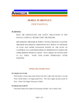
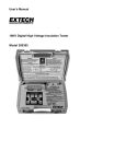
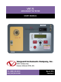
VBT-75
VACUUM BOTTLE TESTER
USER’S MANUAL
Vanguard Instruments Company, Inc.
1520 S. Hellman Ave.
Ontario, California 91761, USA
TEL: (909) 923-9390
FAX: (909) 923-9391
March 2015
Revision 1
VBT-75 USER’S MANUAL
REV 1
SAFETY SUMMARY
FOLLOW EXACT OPERATING PROCEDURES
Any deviation from the procedures described in this operator’s manual may create one or more safety hazards,
damage the VBT-75, or cause errors in the test results; Vanguard Instruments Co., Inc. assumes no liability for
unsafe or improper use of the VBT-75. The following safety precautions must be observed during all phases of test
set up, test hookups, testing, and test-lead disconnects.
SAFETY WARNINGS AND CAUTIONS
This device shall be used only by trained operators. All circuit breakers under test shall be off line and fully
isolated.
SERVICE AND REPAIR
• Do not install substitute parts or perform any unauthorized modification to any VBT-75 test unit.
• Repairs must be performed only by Vanguard Instruments Company factory personnel or by an authorized
repair service provider. Unauthorized modifications can cause safety hazards and will void the manufacturer’s
warranty.
EQUIPMENT RATINGS
IP Rating: The enclosure for the VBT-75 has an IP rating of 32.
Pollution Degree: The VBT-75 has a pollution rating of 2.
Operating Voltage: The VBT-75 is rated for use with an operating voltage of 120V or 240V, auto-ranging ±10% of
selected voltage.
Power Cord: The VBT-75 is supplied with a 16 AWG, 16A power cord with a NEMA 5-15P plug. Replacement cable
shall have the same or better rating and is available through the manufacturer.
VENTILATION REQUIREMENTS
The VBT-75 must be operated with the enclosure lid open.
SAFETY SYMBOLS
Indicates that caution should be exercised
OR
Indicates location of chassis ground terminal
CLEANING
To clean the VBT-75:
• Disconnect all cables and turn the unit off.
• Use a soft, lint-free cloth to wipe all surfaces clean.
• Avoid getting moisture in openings and connectors.
• Don't use any cleaning products or compressed air.
i
REV 1
VBT-75 USER’S MANUAL
TABLE OF CONTENTS
CONVENTIONS USED IN THIS DOCUMENT ..................................................................................... 1
1.0 INTRODUCTION .................................................................................................................... 2
1.1 General Description and Features ................................................................................... 2
1.2 Technical Specifications ................................................................................................... 3
1.3 VBT-75 Controls and Indicators ....................................................................................... 4
2.0 CABLE CONNECTIONS .......................................................................................................... 6
3.0 OPERATING PROCEDURES ................................................................................................... 7
3.1 Set the Date and Time ..................................................................................................... 7
3.2 Changing the LCD Screen Contrast .................................................................................. 8
3.3 Performing a Test ............................................................................................................. 9
3.4 Changing Test Parameters ............................................................................................. 11
LIST OF TABLES
Table 1. VBT-75 Technical Specifications ........................................................................................ 3
Table 2. Functional Descriptions of VBT-75 Controls and Indicators ............................................. 5
LIST OF FIGURES
Figure 1. VBT-75 Controls and Indicators ....................................................................................... 4
Figure 2. VBT-75 Connection Diagram ............................................................................................ 6
ii
REV 1
VBT-75 USER’S MANUAL
CONVENTIONS USED IN THIS DOCUMENT
This document uses the following conventions:
•
A key or switch on the VBT-75 is indicated as [KEY] and [SWITCH].
•
Screen and menu names are referenced as “SCREEN/MENU NAME”.
•
VBT-75 LCD screen output is shown as:
DISPLAY TEXT LINE 1
DISPLAY TEXT LINE 2
•
Warning messages are indicated as:
Warning message
WARNING
•
Important notes are indicated as:
Note details
NOTE
1
VBT-75 USER’S MANUAL
1.0
INTRODUCTION
1.1
General Description and Features
REV 1
The VBT-75 is a microprocessor-based, portable, 75kV dc vacuum bottle tester. This lightweight,
portable tester is designed for testing circuit-breaker vacuum bottles in the field and at the
shop.
Test voltages can be selected from 10 kV dc to 75 kV dc in 5 kV steps. The high-voltage test time
can be set from 5 seconds to 2 minutes. The test voltage is raised to the selected voltage and
held for the test time duration. After the test time duration has elapsed and the leakage current
did not pass the pre-set value of 100 µA, 200 µA, or 300 µA, the test voltage is returned to zero
and a "Pass" message is displayed. If a flash-over condition occurs, such as bottle failure, the
test voltage is immediately turned off, a “Failure” message is displayed on the LCD screen, and
the “TEST FAIL” LED light on the unit is also illuminated.
The presence of high voltage is indicated by an audible tone and an illuminated “HIGH
VOLTAGE” LED light. For additional operator safety, an “ARM” switch must be held down during
testing.
The VBT-75 features a back-lit LCD screen (16 characters by 2 lines) that is viewable in both
bright sunlight and low-light levels. A turn-and-press knob is used to control the unit. An RS232C interface port is provided for factory calibration and diagnostic testing.
The VBT-75 is furnished with a 10-foot test cable that is terminated with a quick-disconnect test
clip. A transportation case is also included.
2
REV 1
1.2
VBT-75 USER’S MANUAL
Technical Specifications
Table 1. VBT-75 Technical Specifications
TYPE
Portable 75 kV vacuum bottle tester
PHYSICAL SPECIFICATIONS Dimensions: 17”W x 10.5”H x 6.5” D (42.7 cm x 26.9 cm x 16.5 cm)
Weight: 10 lbs. (4.53 Kg)
INPUT POWER 2 amps, 90-240 Vac, 50/60 Hz
OUTPUT VOLTAGE
10 kV to 75 kV dc in 5,000 volt steps
OUTPUT RIPPLE VOLTAGE 3% max
DISCHARGE TIME Maximum discharge time for internal high voltage is 3 seconds
DISPLAY
CONTROL
COMPUTER INTERFACE
ENVIRONMENT
HUMIDITY (MAX)
Backlit LCD, 2-lines by 16 characters, visible in bright sunlight and low light
conditions
Single turn-and-press knob selector
One RS-232C port for factory calibration and diagnostics
Operating: -10˚ to 50˚ C (15˚ to +122˚ F);
Storage: -30˚ C to 70˚ C (-22˚ to +158˚ F)
90% RH @ 40˚ C (104˚ F) non-condensing
ALTITUDE (MAX) 2000m (6562 ft) to fully safety specifications
CABLES
One power cord, one ground cable, one 10' high-voltage cable, one 10' highvoltage return cable
SHIPPING CASE Shipping case is included
WARRANTY
One year on parts and labor
The above specifications are valid at nominal operating voltage and at a
temperature of 25°C (77°F). Specifications may change without prior notice.
NOTE
3
VBT-75 USER’S MANUAL
1.3
REV 1
VBT-75 Controls and Indicators
The VBT-75’s controls and indicators are shown in Figure 1 below. A leader line with an index
number points to each control and indicator, which is cross-referenced to a functional
description in Table 2. The table describes the function of each item on the control panel. The
purpose of the controls and indicators may seem obvious, but users should become familiar
with them before using the VBT-75. Accidental misuse of the controls will usually cause no
serious harm. Users should also be familiar with the safety summary found on the front page of
this User’s Manual.
Figure 1. VBT-75 Controls and Indicators
4
REV 1
VBT-75 USER’S MANUAL
Table 2. Functional Descriptions of VBT-75 Controls and Indicators
Item
Number
Panel Markings
1
HIGH VOLTAGE
2
RS-232C
High voltage cable connector
RS-232C interface port for factory calibration and diagnostics
Back-lit LCD screen (2 lines x 16 characters). Visible in bright sunlight and
low-light levels.
3
5
Functional Description
4
120/240 Vac, 2A,
50-60 Hz
F3A250V
Input power connector with built-in fuse holder and power switch
5
GROUND
VBT ground stud. Connect ground stud to substation ground using the provided
cable.
6
TEST FAIL
Test failure indicator. This indicator turns on if the test current exceeds the
present current threshold (100, 200, or 300 μA).
7
CHANGE
SELECT
8
HIGH VOLTAGE
ENABLE
9
PUSH TO
"ARM"
Arm switch; press and hold during testing.
10
GROUND
High voltage return cable connector
VBT turn-and-press control knob.
This indicator turns on when high test voltage is present at the test leads.
VBT-75 USER’S MANUAL
2.0
REV 1
CABLE CONNECTIONS
The VBT-75 comes furnished with one 10-foot (3.05m) high voltage cable and one 10-foot
voltage return cable. Both cables are terminated with alligator clamps that are used to connect
to the vacuum bottle being tested. A typical cable connection is shown in Figure 2 below.
• To protect the VBT-75 against static discharge in the substation, always connect
the unit's ground stud to the substation ground.
WARNING • The circuit breaker must be off-line and completely isolated.
• The vacuum bottle under test should be in the OPEN position.
Figure 2. VBT-75 Connection Diagram
6
REV 1
VBT-75 USER’S MANUAL
3.0
OPERATING PROCEDURES
3.1
Set the Date and Time
Follow the steps below to set the date and time for the VBT-75's internal clock:
a. Start from the "START-UP" menu:
MAIN: <RUN TEST>
14:16:15
Turn the [CONTROL KNOB] until the following screen is displayed:
MAIN: <UTIL>
14:16:18
Press the [CONTROL KNOB].
b. The following screen will be displayed:
UTIL: <SET TIME>
14:16:22
Press the [CONTROL KNOB].
c. The following screen will be displayed:
MM-DD-YY
_
HH:MM
Turn the [CONTROL KNOB] to select the first digit of the month and then press the
[CONTROL KNOB]. The cursor will move over to the second digit of the month.
Continue this process to enter the date and time. When you press the [CONTROL
KNOB] for the last time to set the second digit of the current minute, the date and
time will be set and you will be returned to the "START-UP" menu.
7
VBT-75 USER’S MANUAL
3.2
REV 1
Changing the LCD Screen Contrast
Follow the steps below to adjust the VBT-75's LCD screen contrast:
a. Start from the "START-UP" menu:
MAIN: <RUN TEST>
14:16:15
Turn the [CONTROL KNOB] until the following screen is displayed:
MAIN: <CONTRAST>
14:16:15
Press the [CONTROL KNOB].
b. The following screen will be displayed:
CONTRAST ADJUST
"PRESS" to EXIT
Turn the [CONTROL KNOB] clock-wise or counter-clockwise to adjust the screen
contrast. Press the [CONTROL KNOB] when the contrast is to your liking. You will be
returned to the "START-UP" menu.
8
REV 1
3.3
VBT-75 USER’S MANUAL
Performing a Test
Follow the steps below to perform a test:
NOTE
If you are performing a test for the first time since the unit has been turned on, you
will be prompted for the test duration time, test voltage, and test threshold. If you
have already performed a test since the unit has been turned on, the VBT-75 will use
the test parameters from the first test. To change the test parameters, see section
3.4.
a. Start from the “START-UP” menu:
MAIN: <RUN TEST>
14:16:15
Press the [CONTROL KNOB]
b. The following screen will be displayed:
TIME: <5 sec>
18:02:05
Turn the [CONTROL KNOB] to select the desired test duration and then press the
[CONTROL KNOB].
c. The following screen will be displayed:
VLTG: <10 KV>
18:02:15
Turn the [CONTROL KNOB] to select the desired test voltage and then press the
[CONTROL KNOB].
d. The following screen will be displayed:
THRES: <300 uA>
18:02:20
Turn the [CONTROL KNOB] to select the flash-over threshold and then press the
[CONTROL KNOB].
e. The following confirmation screen will be displayed:
"PRESS" IF OK
10KV 5sec 300uA
Press the [CONTROL KNOB] to confirm the test parameters.
f. The following screen will be displayed:
PRESS RED SWITCH
TO START TEST
9
VBT-75 USER’S MANUAL
REV 1
Press and hold the red [ARM SWITCH].
g. The VBT-75 will initiate the test and start the timer based on the test duration selected.
The screen will be updated with the test voltage and the leakage current as shown
below:
9.9KV
9.86uA
Time: 00:03
h. After the test time duration has elapsed, the test results will be displayed. If the leakage
current did not pass the preset value set in step d, the test voltage is returned to zero
and a "PASS" message is displayed as shown below:
10KV 5sec 300uA
>>PASS<<
However, if a flash-over condition occurred, such as bottle failure, the test voltage is
immediately turned off and a "FAIL" message is displayed as shown below:
10KV 5sec 300uA
>>FAIL<<
The "TEST FAIL" LED on the front panel will also be illuminated to indicate a test failure.
Release the [ARM SWITCH] and press the [CONTROL KNOB] to return to the
"START-UP" menu.
10
REV 1
3.4
VBT-75 USER’S MANUAL
Changing Test Parameters
The first time you perform a test after turning on the VBT-75, you will be prompted for the test
duration time, test voltage, and test threshold. The VBT-75 will use these settings for
performing subsequent tests. Follow the steps below to select different test parameters:
a. Start from the “START-UP” menu:
MAIN: <RUN TEST>
14:16:15
Turn the [CONTROL KNOB] until the following screen is displayed:
MAIN: <SETUP>
14:16:20
Press the [CONTROL KNOB].
b. The following screen will be displayed:
TIME: <5 sec>
18:02:05
Turn the [CONTROL KNOB] to select the desired test duration and then press the
[CONTROL KNOB].
c. The following screen will be displayed:
VLTG: <10 KV>
18:02:15
Turn the [CONTROL KNOB] to select the desired test voltage and then press the
[CONTROL KNOB].
d. The following screen will be displayed:
THRES: <300 uA>
18:02:20
Turn the [CONTROL KNOB] to select the flash-over threshold and then press the
[CONTROL KNOB].
The test parameters will be updated and any subsequent tests that are performed will
use these parameters.
11
1520 S. Hellman Ave • Ontario, CA 91761 • USA
Phone: 909-923-9390 • Fax: 909-923-9391
www.vanguard-instruments.com
Copyright © 2015 by Vanguard Instruments Company, Inc.
VBT-75 User’s Manual • Revision 1.0 • March 3, 2015 • TA