1
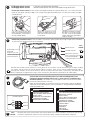
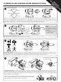
FO
LL IM
O P
W O
CA IN RT
RE ST AN
FU RU T!
LL CT
Y! IO
N
S
OUMAN EH-800 INSTALLATION INSTRUCTIONS
1
Valve opens clockwise
Closed
Open
Valve opens counterclockwise:
Open
Closed
Use the manual control knob to turn the valve all the way to the left, so the valve is either completely open or closed. If
the valve is completely open, the valve direction in the controller’s menu must be changed to open in the counterclockwise direction. (see section 14). Remove the manual control knob and detach the two cover screws from the valves. Note!
Esbe VRG and Belimo R4…D(K) valves have their own mounting kits as optional equipment.
2
installation
bracket
cover screws
Note!
Use the EH-80 installation bracket when changing EH-80 to the newer
EH-800.
The adapter (section 3)
must be changed.
Fasten the installation bracket to the valve using the cover screws as shown in the diagram. The installation bracket
has several holes. Use the ones that match the valve type.
3
Fasten the adapter to the axle of the valve using the tightening band so that the star-shaped piece is straight and the
adapter’s teeth are not in the same place as the tapered side of the axle. Place the manual control lever on the axle of
the adapter with the concave side toward the controller and pointing to the left (9 o’clock position).
4
The amount of space the EH-800
controller takes up
46
125
70
46
85
Fasten the controller so that the spring on the end of the adapter goes into the star-shaped hole on the bottom of the
controller and then line the axle of the adapter up to the pin of the installation bracket. Press the controller into place. If
you cannot install the controller ”right side up” because of a lack of space, you can install it upside down and turn the controller’s display
from the controller’s device settings.
User the manual control lever to check that the valve turns freely over
the full range of movement (90°). You must press the manual control
knob while you are turning the manual control lever.
5
H1 Supply water sensor is already attached to the controller.
H2 Supply water sensor connect the external unit to the controller using the RJ45-2
Fasten the surface sensor to the surface of the pipe entering the network about 0.5...1.5 m from the valve
either on the top or side of the pipe. The surface of the pipe should be clean, rust free and smooth; the pipe
can be painted.
Cut the corner of the bag
open and squeeze the grease
on the bottom surface of the
sensor (cooper plate) .
6
Wrap the fastening strap
around the pipe. Make sure
that that the surface sensor
is not loose.
Wrap the strap around the pipe again if it is long enough.
Cut the strap to the proper
length along the groove between the holes.
Detach the protective cover of the controller’s connection space (slides off at a right angle to the controller)
and connect the outdoor sensor to the controller.
Power source
GSM modem and
EXU-800
external unit connection (see separate instructions)
24 V
AC/DC
Outdoor sensor
Additional connections using the cord
and connecting box
(measurements 3 and 4)
Position the outdoor sensor (TMO) in a shady place on the northern side of the building at a height of about
2.5 meters. Do not install the sensor directly above a window, door, vent or sensor cable protection tube
coming from indoors, or next to an exhaust duct or any other source of heat. If necessary, the cable can be
either shortened or lengthened using a screw connector. (No special requirements for cable type).
Connect the cord and connecting box if you take something that is not
included in the basic package into use (e.g., room sensor or something else
mentioned below). The cord and connecting box can be used to connect 2 different things (measurements 3 and 4).
Open the connecting box and make the necessary connections (see the list below)
Select the use for measurements 3 and 4. (section 11) during controller initialization
(heating controller use).
7
Connecting box
Wh
Bl
Re
Meas. 3
Meas. 4
Measurement 3
Not in use
TMR Room measurement
TMR / SP Room measurement
Return water
Temperatur of accumulator
Temperature of boiler
Measurement 3 (labelled)
Measurement 4
Not in use
Home/Away -switch
8
24 V
AC/DC
TMR / SP Room temp.potentiometer
Return water
TMR / P Room compensation
Temperatur of accumulator
Temperature of boiler
Measurement 4 (labelled)
Pressure alarm
Burner alarm
Pump alarm
Boiler alarm
Alarm (labelled)
Plug one end of the cord into the wall and the other end into the controller. We recommend putting
the cord in a protective sleeve. Put the connection space’s protective cover back into place.
OK
CONTROLLER SETTINGS
9
Changing the language:
EH-800 setup
Kieli/Språk/Language
Suomi >
Press the control knob (=OK),
turn the control knob to change
the language and press OK.
Time and date setting >
Measur. channels settings >
Heating mode Radiator heating, normal >
Kieli/Språk/Language
Suomi
Svenska
English
10 Turn the control knob to go to time and date settings and press OK.
Time
EH-800 setup
Suomi >Give the hours;
Language/Kieli/Språk
Time and date setting >
Measur. channels settings >
Heating mode Radiator heating, normal >
Press OK. Select either a time or date and press OK.
ESC to exit from time and date settings
19:44
Date
Give the day:
Tu 29.10.2009
pp.kk.vvvv
hh:mm
Set the hours and press OK
to confirm. Set the minutes
and press OK to confirm.
First set the day, then the
month and then the year. Press
OK. (the name of the weekday
is automatically updated).
11 Taking additional connections (measurements 3 and 4) into use using the cord and
connecting box
If you do not take additional connections into use (see section 7), go to section 12.
EH-800 setup
Measurements
Language/Kieli/Språk
English>
Measurement 3
Not in use >
Time and date setting>
Measurement 4
Heating mode Radiator heating, normal >
Press OK. Select the measurement use (see alternatives, section 7).
TMR Room measurement >
Measurement 3 (4) or alarm can be freely labelled.
The uses for measurements 3 and 4 appear on the
display. Press ESC to exit.
Measur. channels settings>
Measurements
Measurement 3
Measurement 4
Not in use >
Not in use >
Labelling: Use the control knob to select a letter. Press OK to confirm. Press OK for a number of
seconds to confirm the name. Press ESC to delete the letter. Press ESC for a number of seconds to
delete the name. If you take a measurement into alarm use, you can select whether the controller
sounds an alarm when the switch opens or when it closes. The default is that the controller gives
an alarm when the switch opens. (see user manual p.24).
12
Heating mode selection
Heating mode
Using EH-800 as a heating controller
Measur. channels settings >
Floor heating, damp rooms
Direction on valve
Radiator heating, normal
Heating mode
Radiator heating, normal >
Open clockwise >
Start-up with new settings >
Floor heating, normal
Radiator heating, steep curve
Contant temperature controller
The controller has factory settings for normal ra Concrete floor drying
diator heating. Floor heating, normal: normal floor
heating Floor heating, damp rooms: select this when the controller only heats tiled floors (when you
want a comfortably warm floor and/or a dry floor in the summer). Radiator heating, steep curve: select
this when your house has poor insulation or the radiators do not give off enough heat. The constant
temperature controller and concrete floor drying are special applications of the controller. (additional
information about heating modes in the user manual on p. 27). After initialization, the heating mode
selection can be found from the controller at ”Device settings -> H1 Process settings”.
13 Setting the valve direction for the controller
Direction of valve
Using EH-800 as a heating controller
Measur. channels settings >
Heating mode
Direction on valve
Radiator heating, normal >
Open clockwise >
Open clockwise
Open counterclockwise
Start-up with new settings >
As a default the valve opens when it is turned clockwise. If the controller is installed for a valve that opens
when it turns counterclockwise, the valve direction in the controller’s menu must be changed to open in
the counterclockwise direction. (see section 1).
Additional information on page 27 of the user manual. Changing the direction of the valve, see “Device settings”.
Valve direction: The range of movement of boiler valves is mechanically limited to 90°. Therefore, it is easy
to find the limits by turning the valve to the extreme limits using the manual control knob or axle. Sometimes it may be difficult to determine the opening direction of a 3-way valve installed in the network, e.g., if
the manual control knob is missing or the scale plate of the valve is installed incorrectly. To make it easier to
determine the direction, a few hints are given below for the most common mixing valves on the market.
ESBE (3MG): The slide of the valve can be turned 360°. Turn the valve all the way to
the left (9 o’clock). The tapered side of the valve axle always faces toward the slide. (the
branch on the tapered side is closed).
Open clockwise
Open counterclockwise
Boiler
or
accumulator
Boiler
or
accumulator
TERMOMIX: The slide of the valve is always on the opposite
side of the taper at the end of the axle.
If you can’t get the valve turned so that the slide moves between
the hot water branch and circulating water branch, the position
of the valve cover must be changed. We recommend having
a plumber change the direction because of the risk of water damage and burns.
Measur. channels settings >
Heating mode
Direction on valve
Radiator heating, normal >
Open clockwise >
Start-up with new settings >
15 Taking the second control circuit into use
Device settings > H2 Process settings
H2 Process settings
Heating mode
Actuator selection
Actuator driving time
Heating curve type
Name of regul. circuit
In use >
Radiator heating, normal >
0-10V >
150 s >
3-point heating curve >
Radiator circuit >
Käynnistys uusilla asetuksilla >
The controller has now been taken into use as a
one circuit heating controller.
The EXU-800 external unit must be in use to take
the second control circuit into use. Connect the supply water sensor (strip connector 11 and ground) and
the actuator (strip connector 8 (24VDC OUT), 9 (Y)
and ground) of the second control circuit to the external unit. Connect EXU-800 to the controller using the
RJ45-2 connection.Take the H2 control circuit into use
through point H2 process settings in the controller’s
device settings (see user manual p. 32).
60
70 80
90
In floor heating solutions
In floor heating solutions it is important to make sure that exessively hot water which could damage structures or surfaces doesn´t ever get into the network. A mechanical thermostat should be installed on a supply water pipe
which stops the circulation pump in case of overheating. Ouman Oy has in
it`s product range a surface mounted thermostat C01A.
0
20 30 4
Using EH-800 as a heating controller
Press OK. The controller will take into use the new
settings which are determined by the heating mode.
The new settings can be found in the controller under
“Device settings”.
50
14 Start-up with new settings
The branch is completely open when it is in
the same direction as the tapered side.
AC 250V 15 (2,5) A
0
2 1 3
Pump
control
230 VAC
Pump
control
HINTS FOR FIRST-TIME USE
If room temperature measurement is not in use: At first the radiator thermostats should be turned fully open. Set the fine
adjustment so that the first time there is below freezing temperatures outdoors, the room temperature stays about 1 °C higher than what you want it to be. After that turn down the radiator thermostats just enough to obtain the desired room temperature. This prevents the room temperature from dropping on windy days, because the radiator thermostats will be able to
increase the heating level.
Room temperature measurement in use: Room control can, if necessary, raise or lower the temperature level of the whole
house and so the small temperature increase in the network mentioned before is not needed. Also you get more even temperature control in houses with floor heating when room temperature measurement is taken into use.
Warranty: Ouman Oy has given EH-800 a three year warranty for the device. The warranty covers repair of the device at Ouman Oy:s factory and includes necessary spare parts. The warranty is not in effect if the device has been installed incorrectly
or mechanically damaged. The warranty does not cover indirect or consequential loss or damages. It does not cover the cost
connected with finding a fault, detaching the device, or sending or installing the device.
OUMAN OY
www.ouman.fi
[email protected]
Factory and Oulu sales office:
Voimatie 6
Tel. 0424 8401
90440 Kempele
Fax. 08 815 5060
Espoo sales office:
Upseerinkatu 3 C
02600 Espoo
Tel. 0424 840 202
Fax. 09 4780 1030