1
®
EVOLUTION 4100
Thermal Imaging System
OPERATION AND INSTRUCTIONS
" WARNING
THIS MANUAL MUST BE READ
CAREFULLY BY ALL INDIVIDUALS
WHO HAVE OR WILL HAVE THE
RESPONSIBILITY FOR USING OR
SERVICING THE PRODUCT.
Lik e any piec e of c omplex
equipment, the unit will perform
as designed only if it is used and
maintained in accordance with
the manufacturer’s instructions.
OTHERWISE IT COULD FAIL TO
PERFORM AS DESIGNED AND
RESULT IN SEVERE PERSONAL
INJURY OR DEATH.
The warranties made by Mine
Safety Appliances Company with
respect to the product are voided
if the product is not used and
serviced in accordance with the
instructions in this manual.
Please protect yourself and
others by following them. We
encourage our customers to write
or call regarding this equipment
prior to use or for any additional
information relative to use or
repairs. During regular working
hours, call 1-877-MSA-FIRE.
By order of the US Department
of State, Office of Defense Trade
Controls, this Thermal Imaging
Came ra ma y not be res old,
re -e xport ed, transfe rred, or
otherwise disposed of outside of
the country named as the location
of foreign end use, either in its
original form or after being
incorporated into other end items,
without the prior written approval
of the Office of Defense Trade
Controls, U.S. Department of
State. Violation of this regulation
may result in fine or imprisonment
in accordance with 22 CFR, Parts
120-130.
Be Sure.
Choose MSA.
(L) Rev 1
MINE SAFETY APPLIANCES COMPANY
PITTSBURGH, PENNSYLVANIA, U.S.A. 15230
© MSA 2004
10054951
TABLE OF CONTENTS
BEFORE USE / DESCRIPTION . . . . . . . . . . . . . . . . . . .
INTRODUCTION . . . . . . . . . . . . . . . . . . . . . . . . . . . . . .
FEATURES AND BENEFITS . . . . . . . . . . . . . . . . . . . . .
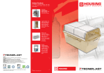
BEFORE USE / DESCRIPTION . . . . . . . . . . . . . . . . . .
ABOUT THE CAMERA . . . . . . . . . . . . . . . . . . . . . . . . .
Figure 1. The Evolution® 4100 TIC . . . . . . . . . . . . .
Figure 2. Entire Entry Team Can View . . . . . . . . . .
4
4
4
4
4
4
4
Large, High-Definition Display . . . . . . . . . . . . . . . . . . . . .
4
Specifications . . . . . . . . . . . . . . . . . . . . . . . . . . . . . . . . .
Figure 3. Ergonomic Balance . . . . . . . . . . . . . . . . . .
5
5
and Easy Hand-Off . . . . . . . . . . . . . . . . . . . . . . . . . . . . . .
5
Figure 4. Heat-Seeker Indicator System . . . . . . . . .
TIC ACCESSORIES . . . . . . . . . . . . . . . . . . . . . . . . . . . . .
5
6
TIC Configurations and Accessories . . . . . . . . . . . . . . . .
6
Evolution 4100 TIC Standard Components . . . . . . . . .
Other Options . . . . . . . . . . . . . . . . . . . . . . . . . . . . . . . . .
WARNINGS AND CAUTIONS . . . . . . . . . . . . . . . . . . . . .
" WARNING . . . . . . . . . . . . . . . . . . . . . . . . . . . . . . .
" CAUTION . . . . . . . . . . . . . . . . . . . . . . . . . . . . . . .
LIMITATIONS . . . . . . . . . . . . . . . . . . . . . . . . . . . . . . .
OPERATION . . . . . . . . . . . . . . . . . . . . . . . . . . . . . . . . . . .
OPERATION . . . . . . . . . . . . . . . . . . . . . . . . . . . . . . . . . .
Getting Started . . . . . . . . . . . . . . . . . . . . . . . . . . . . . . . .
TURNING THE CAMERA ON AND OFF . . . . . . . . . . .
Normal Mode . . . . . . . . . . . . . . . . . . . . . . . . . . . . . . . . .
Standby Mode . . . . . . . . . . . . . . . . . . . . . . . . . . . . . . . .
Turning the Camera OFF . . . . . . . . . . . . . . . . . . . . . . .
USER INTERFACE- INDICATORS AND WARNINGS .
On-Screen Indicators . . . . . . . . . . . . . . . . . . . . . . . . . . .
Available Display LED Indicators (FIGURE 6) . . . . . . .
LED Indicators . . . . . . . . . . . . . . . . . . . . . . . . . . . . . . . .
On-Screen Indicators . . . . . . . . . . . . . . . . . . . . . . . . . .
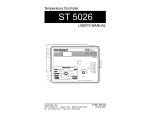
Figure 5. Camera Buttons . . . . . . . . . . . . . . . . . . . . .
LED Indicators . . . . . . . . . . . . . . . . . . . . . . . . . . . . . . .
" WARNING . . . . . . . . . . . . . . . . . . . . . . . . . . . . . . .
Figure 6. User Interface Display LED Indicators &
Warnings . . . . . . . . . . . . . . . . . . . . . . . . . . . . . . . . . .
Additional Indicators . . . . . . . . . . . . . . . . . . . . . . . . .
DIRECT VIDEO CONNECTION . . . . . . . . . . . . . . . . .
FACTORY UPGRADEABLE
FEATURES & ACCESSORIES . . . . . . . . . . . . . . . . . . .
Remote Wireless Video Transmission . . . . . . . . . . . . .
Introduction . . . . . . . . . . . . . . . . . . . . . . . . . . . . . . . . . .
Remote Wireless Video Transmitter System Specifications
Operation and Use
of the Remote Wireless Video Transmission System
" WARNING . . . . . . . . . . . . . . . . . . . . . . . . . . . . . .
Figure 7. Blue Transmitter Button Location . . . . . .
FCC REGISTRATION FORMS . . . . . . . . . . . . . . . . . . .
FCC REGISTRATION REQUIREMENTS . . . . . . . . . .
BATTERY CARE AND INSTALLATION . . . . . . . . . . . .
RECHARGEABLE NIMH BATTERIES . . . . . . . . . . . .
THEORY OF OPERATION . . . . . . . . . . . . . . . . . . . . .
BATTERY INSTALLATION AND CARE . . . . . . . . . . .
BATTERY MAINTENANCE . . . . . . . . . . . . . . . . . . . . .
EVOLUTION 4000 SERIES
TRUCK MOUNTED CHARGER . . . . . . . . . . . . . . . . . . .
6
6
7
7
7
7
8
8
8
8
8
8
8
8
8
8
8
8
8
9
9
9
10
10
11
11
11
11
11
11
11
12
12
13
13
13
13
13
14
ABOUT THE CHARGER . . . . . . . . . . . . . . . . . . . . . . .
Specifications . . . . . . . . . . . . . . . . . . . . . . . . . . . . . . . . .
TIC VEHICLE-MOUNTED CHARGING SYSTEM
COMPONENTS . . . . . . . . . . . . . . . . . . . . . . . . . . . . . . .
OPTIONAL COMPONENTS . . . . . . . . . . . . . . . . . . . . .
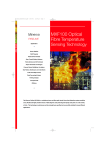
Figure 8. The Evolution® 4000 Series . . . . . . . . . . .
14
14
14
14
14
TIC Vehicle-Mounted Charging System . . . . . . . . . . . . . . 14
INSTALLATION . . . . . . . . . . . . . . . . . . . . . . . . . . . . . . . .
OPERATION . . . . . . . . . . . . . . . . . . . . . . . . . . . . . . . . . .
Getting Started . . . . . . . . . . . . . . . . . . . . . . . . . . . . . . . .
" WARNING . . . . . . . . . . . . . . . . . . . . . . . . . . . . . . .
What You will Need: . . . . . . . . . . . . . . . . . . . . . . . . . . .
INSTALLATION GUIDELINES . . . . . . . . . . . . . . . . . . . .
Mounting Hanging Channels . . . . . . . . . . . . . . . . . . . . .
Figure 9. Installation Hardware Kit (provided) . . . . .
Figure 10. Drill Holes in Cab Wall . . . . . . . . . . . . . .
Figure 11. Bolt Unistrut Channels in Place . . . . . . .
Mounting Evolution 4000 Series TIC Charger to
Channel Using Rear Panel . . . . . . . . . . . . . . . . . . . . . .
Mounting Evolution 4000 Series TIC Charger to
Channel Using Side Panel . . . . . . . . . . . . . . . . . . . . . .
Electrical Connections . . . . . . . . . . . . . . . . . . . . . . . . . .
Power Requirements . . . . . . . . . . . . . . . . . . . . . . . . . . .
Electrical Specifications . . . . . . . . . . . . . . . . . . . . . . . . .
Installation . . . . . . . . . . . . . . . . . . . . . . . . . . . . . . . . . . . .
Figure 12. Correct Hardware Placement . . . . . . . . .
15
15
15
15
15
15
15
15
15
15
16
16
16
16
16
16
16
for Rear Panel Mounting . . . . . . . . . . . . . . . . . . . . . . . . . 16
Figure 13. Connection of the Power Hookup Cable
Figure 14. Wiring Diagram . . . . . . . . . . . . . . . . . . . .
"! CAUTION/WARNING . . . . . . . . . . . . . . . . . . . . . .
Operation . . . . . . . . . . . . . . . . . . . . . . . . . . . . . . . . . .
Battery LED Indicators . . . . . . . . . . . . . . . . . . . . . . . . . .
Power Status LED Indicator . . . . . . . . . . . . . . . . . . . . .
MAINTENANCE, TROUBLESHOOTING, & SERVICE . .
Cleaning . . . . . . . . . . . . . . . . . . . . . . . . . . . . . . . . . . . . .
Cleaning the Charging Connector . . . . . . . . . . . . . . . . .
" WARNING/CAUTION . . . . . . . . . . . . . . . . . . . . . .
TROUBLESHOOTING . . . . . . . . . . . . . . . . . . . . . . . .
Troubleshooting Guidelines . . . . . . . . . . . . . . . . . . . . . .
" WARNING . . . . . . . . . . . . . . . . . . . . . . . . . . . . . . .
16
17
18
18
18
18
19
19
19
19
19
19
19
Field Repairs and Maintenance . . . . . . . . . . . . . . . . . . . . 20
Internal PCB Fuse Replacement . . . . . . . . . . . . . . . . . . 20
Figure 15. Location of Internal Fuse, Fuse Interface
20
Cable Connector and Main Power Phoenix Connector . 20
Interface Cable Replacement . . . . . . . . . . . . . . . . . . . .
WARRANTY AND SERVICE . . . . . . . . . . . . . . . . . . . . . .
MAINTENANCE AND ADJUSTMENTS . . . . . . . . . . . . .
General Maintenance . . . . . . . . . . . . . . . . . . . . . . . . . . .
Cleaning . . . . . . . . . . . . . . . . . . . . . . . . . . . . . . . . . . . . .
" WARNING/CAUTION . . . . . . . . . . . . . . . . . . . . . .
SERVICE . . . . . . . . . . . . . . . . . . . . . . . . . . . . . . . . . .
21
22
23
23
23
23
23
MSA FACTORY REPAIR & SERVICE POLICY CARD
24
EVOLUTION 4000 TIC VEHICLE-MOUNTED CHARGER
SPARE PARTS LIST. . . . . . . . . . . . . . . . . . . . . . . . . . . . . 25
EVOLUTION 4100 SPARE PARTS LIST . . . . . . . . . . . . 25
3
(L) Rev. 1 - 10054951
BEFORE USE / DESCRIPTION
• Preplanning/Fire code inspections
• Overhaul
• Assistance for law enforcement
INTRODUCTION
BEFORE USE / DESCRIPTION
The Evolution 4100 TIC is a highly sophisticated
piece of electronic equipment. The unit was
designed to withstand the firefighting conditions
of heat, driving spray, and frequent impact
normally seen by a firefighter. Extension of these
demands may damage the camera and render it
inoperable. It is not recommended that the
camera run for extended periods, particularly in
high-heat conditions.
The Evolution 4100 TIC is intended as an aid to
fire and rescue operations in conditions of poor
visibility created by smoke and darkness. It is not
a replacement for standard firefighting techniques
and precautions. Users must ensure that the fire
department’s standard operating procedures are
followed while using the camera.
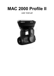
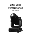
ABOUT THE CAMERA
Figure 1. The Evolution® 4100 TIC
Congratulations on the purchase of your new MSA
Evolution 4100 Thermal Imaging System! This
hand-held unit provides advanced thermal imaging
technology backed by years of MSA quality,
dedication, and service.
The Evolution 4100 TIC is:
• equipped with a state-of-the-art microbolometer
thermal detector to provide the clearest
high-definition images available in fire and
non-fire environments
• equipped with a large-screen, high definition
display to allow for all firefighters on the entry
team to view the action
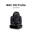
• designed with the most ergonomically correct
balance, with the center of gravity located in the
users hand
The Evolution 4100 Thermal Imaging Camera
(TIC) is designed to assist firefighters to see in
low visibility conditions of smoke and darkness.
This high definition thermal imaging camera
provides the latest in available thermal imaging
technology for the fire service.
FEATURES AND BENEFITS
The Evolution 4100 Thermal Imaging Camera
(TIC) can be used to aid firefighting in scenarios
such as:
•
•
•
•
•
•
•
•
•
Search and rescue missions
Initial size-up/Scene assessment
Locating the seat of the fire
Locating fire extension
Identifying potential flashover situations
Determining entry and ventilation points
Hazmat situations
Incident command "eye-in-the-sky"
Response vehicle navigation
(darkness or heavy smoke)
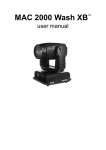
Figure 2. Entire Entry Team Can View
Large, High-Definition Display
4
(L) Rev. 1 - 10054951
• available with an optional remote wireless video
transmission system for seamless
communication with incident command
• patent pending.
This device complies with part 15 of the FCC
Rules. Operation is subject to the following two
conditions: (1) This device may not cause
harmful interference, and (2) this device must
accept any interference received, including
interference that may cause undesired operation.
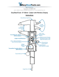
Specifications
Figure 3. Ergonomic Balance
and Easy Hand-Off
CASE
• completely usable with gloves, including
battery changes
• durable to withstand a 4.5-foot drop from any
plane onto a concrete surface up to three
consecutive times
• dust and water-resistant to withstand short-term
immersion in up to three feet of water
per IP67 specifications
• equipped with the Heat-Seeker Indicator System
which readily identifies the hottest point of the
fire with red highlights on an otherwise
black-and- white image
• available with an optional Quick-TempTM
Indicator that identifies the relative temperature
of surrounding objects
Flame retardant (material
passes simulated NFPA direct
CONSTRUCTION flame exposure test). IP67
[withstands immersion to
3 feet (1 meter)]
HEIGHT
APPROXIMATE
WIDTH
DIMENSIONS
LENGTH
8.5 inches (216 mm)
7.5 inches (191 mm)
15.0 inches (381 mm)
(includes visor)
SENSOR
Uncooled microbolometer
ARRAY SIZE
160 X 120
WEIGHT
5.3 lbs. (base TIC without
battery)
POWER
SOURCE
One or two 7.2V rechargeable
DR30 NiMH batteries
POWER
USAGE
AT 72oF (22oC)
10.8 W nominal
1 NiMH PACK
2.5 hours at nominal 72oF
(22oC)
2 NiMH PACKS
5.0 hours at nominal 72oF
(22oC)
OPERATING
TIME
FIELD OF
VIEW
54.4o diagonal
0.07oC Nominal
NETD
VIDEO
OUTPUT
Note:
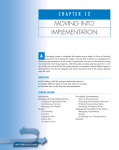
Figure 4. Heat-Seeker Indicator System
HIGH
SENSITIVITY
0.1o K maximum
LOW
SENSITIVITY
0.6o K maximum
RS-170A, 160 x 120 lines
The Evolution 4100 TIC detects thermal
energy radiated/generated from
surrounding objects and converts
this energy into a visual image.
• Hot objects appear white.
• Cold objects appear black.
5
(L) Rev. 1 - 10054951
TIC ACCESSORIES
TIC Configurations and
Accessories
The Evolution 4100 TIC can be purchased as a
complete kit with accessories or can be custom
configured to your requirements under the
Assemble to Order (ATO) System. There are
several part-numbered kits to choose from. Please
see the Evolution 4100 Brochure for complete
ordering information.
Evolution 4100 TIC Standard
Components
• Shoulder Strap - Attaches to the TIC to allow
for easy carriage of the camera while not in use.
FDNY strap available with seat belt style
disconnect.
• DC Cigarette Adapter - Allows battery to be
charged from a DC jack.
Display Sun Shroud
Display Shroud allows for crisp/clear viewing of
the LCD screen while in bright sunlight.
Reflective Trim Kit
All Evolution TICs come standard with the
following items:
• Thermal Imaging Camera
• Two Rechargeable NiMH Batteries
• Standard Universal Charger Kit with Cigarette
Lighter Adapter or Truck Mounted Charger
• BNC Video Out Connector
• Instruction Manual.
The Evolution 4100 TIC can be ordered as
standard kit part numbers or as Assemble to
Order. See ordering information.
Other Options
Carrying Attachments
The Evolution 4100 TIC comes standard with a
caribiner attachment. Additionally, users can
choose to purchase any one of three optional
carrying attachments:
• Wrist Strap/Bunker Clip - Attaches to the TIC
and includes a clip for securing the TIC to
bunker gear while not it use.
Reflective Trim allows the user to add additional
visibility for the Evolution 4100 TIC.
Disposable Display Covers
A package of three Disposable Display Covers
provides replaceable protection of the 3.5" LCD.
Custom Carrying Case
The durable Carrying Case allows for storage and
transport of the TIC, batteries, charger, and
carrying attachments.
Mounting Bracket
The non-charging Mounting Bracket enables
convenient storage of the Evolution 4100 TIC.
Tripod
The Tripod allows for stationary viewing of the
thermal imaging camera. The Tripod must be used
with the Tripod Adapter.
Transmitter/Receiver
Two channel analog Transmitter and two Receiver
options are available.
6
(L) Rev. 1 - 10054951
WARNINGS AND CAUTIONS
" WARNING
1. The user must be trained and thoroughly
familiar with the proper operation and
limitations of the thermal imaging system
prior to use. Use in controlled live-burn
exercises is suggested before using the
equipment in actual emergency situations.
Improper use of the equipment in a
hazardous atmosphere could result in
serious personal injury or death.
2. Do not rely on the thermal imaging system
as the sole means of navigation or deviate
from standard fire-fighting navigational
practices during use. Although the system
provides an image in dark and smoky
environments, the user may become
disoriented or lost in such environments if
the system becomes inoperative.
Most electronic devices will cease to operate at
certain high temperature extremes. Tests on
the Evolution 4100 TIC indicate that it will
provide an acceptable image when
subjected to an ambient temperature of
approximately 120°C (248°F) for about ten
minutes. Exposure to conditions exceeding
these will result in deterioration and loss of
image.
3. Thermal energy is not transmitted through glass
or underwater and may be reflected off of
smooth surfaces. Disorientation may occur if
the user is unaware of these properties.
4. This thermal imaging system is not rated as
"Intrinsically Safe." Do not use the system in
environments or atmospheres where static
or spark may cause an explosion.
5. Before entering a hostile environment, test the
thermal imaging system as specified in the
instructions to ensure that it is functional.
After each use, inspect the system to
determine if servicing is required.
6. Exposure to high temperature environments
for an extended period of time may cause
degradation or loss of thermal image. Avoid
heat saturation or over exposure of the
equipment. If degradation of the thermal
image is observed, remove the equipment
from the high heat environment and allow it
to cool until the thermal image returns to
normal; otherwise, the system may become
inoperative.
7. Replacement batteries must exactly match the
ratings and configuration of those supplied
with the equipment. Use of unapproved
batteries may render the system inoperative.
8. Do not remove the thermal imaging camera
cover or casing as the system operates on
high voltage. Only authorized personnel may
service the unit.
FAILURE TO FOLLOW THE ABOVE WARNINGS
CAN RESULT IN SERIOUS PERSONAL INJURY
OR DEATH.
" CAUTION
1. Ensure battery is fully charged before use. If
not fully charged, the system will not operate
for the specified amount of time. Monitor
battery level during use and exit the
hazardous area when a low battery warning
is observed.
2. Electromagnetic radiation (radio
transmissions) may cause interference.
Minimize nearby radio transmissions if
excessive interference occurs.
3. To avoid lens fogging, the user may coat
the lenses and view finder with anti-fog
material (MSA P/N 13016).
4. Do not point the thermal imaging camera
directly at the sun; otherwise, damage to the
detector may occur.
5. Do not drop the thermal imaging camera.
Although the camera is designed to
withstand normal impacts that occur in fire
service, such impacts may alter the focus or
damage the unit.
FAILURE TO FOLLOW THE ABOVE CAUTIONS
CAN RESULT IN PERSONAL INJURY OR
EQUIPMENT DAMAGE.
LIMITATIONS
1. Although the Evolution 4100 TIC is IP67
waterproof, the system does not provide
underwater thermal images.
2. The Evolution 4100 TIC does not provide
images through glass, water, or shiny
objects; these surfaces act like mirrors to the
system.
3. The Evolution 4100 TIC does not improve
impaired vision. Users with impaired vision
should continue to use ophthalmic devices
while using the system.
7
(L) Rev. 1 -10054951
OPERATION
OPERATION
Standby Mode
Getting Started
To conserve battery consumption, the camera is
equipped with a Standby Mode feature.
The rechargeable batteries supplied with the
Evolution 4100 TIC must be fully charged before
use. Also, periodically check and replace the
battery in an actively-used imager.
• See "Battery Care and Installation" later in this
manual.
TURNING THE CAMERA ON AND OFF
Normal Mode
1. To turn the
camera ON,
press the
POWER
(green)
button
directly under
the view
finder (see
FIGURE 5)
and hold for
approximately
one second.
3. To activate, press the POWER (green)
button until:
• The display shuts OFF.
• The flashing GREEN POWER LED
activates.
4. To return to Normal Mode from Standby Mode,
press the POWER (green) button until:
• The display immediately reactivates
without warm-up time.
• The flashing GREEN LED changes to
solid GREEN.
Turning the Camera OFF
5. To turn the camera OFF, press and hold the
green POWER button in for four seconds.
• As a safety feature to avoid inadvertent
power-offs, the green POWER button
must be held for four seconds to turn OFF
the camera.
• The green POWER LED flashes during
the power-off countdown to confirm
effective button press.
• When all LED indicators shut OFF,
the user may release the green
POWER button.
• The camera is now OFF.
USER INTERFACE- INDICATORS AND
WARNINGS
On-Screen Indicators
A Low sensitivity firefighting mode indicator
B Shutter indicator
Figure 5. Camera Buttons
2. Verify the camera is functioning by aiming at
an object or person until the thermal image
appears in the camera viewer.
• The thermal imaging camera is now ready
for use.
NOTE: The Evolution 4100 POWER button
has a momentary pushbutton switch
that requires deliberate, one-second
activation to operate. This is to
prevent accidental shut-OFF. Rapid
repeated depression of the POWER
button may cause the TIC start-up
software to lock, and a picture will
not display (LEDs may still activate).
If this condition occurs, simply turn
the TIC OFF and back ON using
slow, deliberate button presses.
C
Optional Quick - Temp Indicator/Digital
Temperature.
Available Display LED Indicators
(FIGURE 6)
LED Indicators
D Over - Temperature Warning
E System Status Indicator
F
Battery Status Indicators
G
Transmitter Indicator (optional).
On-Screen Indicators
A - Low Sensitivity Mode Indicator - An
on-screen sensitivity indicator ("L") informs the
user when the camera is in the low sensitivity
(Firefighting) mode.
8
(L) Rev. 1 - 10054951
Figure 6. User Interface Display LED Indicators
and Warnings
• This mode occurs when the thermal imager
LED Indicators
senses an environment above 150°C.
• Dynamic Range is extended while in this mode to
provide greater image details of the surroundings.
D - Over Temperature Warning - Warning
activates when the system electronics approach
maximum recommended operating temperature limits.
• Not lit indicates system is within
operational thermal limits
In high-heat conditions, the TIC will automatically
enter the Low Sensitivity (or Firefighting) mode.
While in Low Sensitivity mode, the TIC’s dynamic
range is extended, thereby allowing the user to
make better distinction of objects and people within
a higher temperature range. When the Evolution
4100 TIC is in Low Sensitivity mode, the letter "L"
appears in the lower left corner of the display.
B - Shutter Indicator - An on-screen indicator
that tells the user when the TIC is shuttering
appears as a green square in the upper left
corner of the display.
While the TIC is in operation, it is periodically
necessary for the TIC to refresh the focal plane in
order to operate properly. This occurs via an
internal shutter mechanism. When the TIC
shutters, the image on the display temporarily
freezes for about one second. Shuttering can
occur more frequently in higher heat conditions.
This is normal for all microbolometer - based TICs.
C - Optional Quick-Temp Indicator - On-screen
operating Quick Temp spotter and vertical bar
gauge spans temperatures from 32°F (0°C) to
300°F (150°C) in High Sensitivity mode and 32°F
(0°C) to 1000°F (500°C) in Low Sensitivity mode
for objects located in the spotter. The digital
temperature feature displays the approximate
number value of the temperature of objects
located in the spotter.
• Flashing Red indicates the TIC has
exceeded recommended operational
thermal limits.
" WARNING
Most electronic devices will cease to operate
at certain high temperature extremes. Tests
on the Evolution 4100 TIC indicate that it will
provide an acceptable image when subjected
to an ambient temperature of approximately
120°C (248° F) for about ten minutes.
Exposure to conditions exceeding these will
result in deterioration and loss of image.
E - System Status Indicator - A single LED
shows the operational status of the TIC.
• Green indicates the TIC is ON and fully operational
• Flashing Green indicates the TIC is ON and in
power-saving Standby mode.
F - Battery Status Indicator - Battery capacity is
shown by a row of three LEDs: one green, one
yellow, and one red. Only one of the three battery
status indicators will be illuminated at any one time.
• Green indicates full or nearly full battery capacity
• Yellow indicates marginal battery capacity
9
(L) Rev 1 - 10054951
• Red indicates battery warning and nominally 15
minutes of battery life remaining
• Flashing Red indicates battery shutdown is
imminent (about one minute of warning time).
Additional Indicators
Optional Heat Seeker Indicator - The optional
Heat Seeker indicator shows any portion of the
screen in red:
• When in high sensitivity mode (low
temperatures) any portion of the scene which is
above 288°F (142°C)
• When in low sensitivity mode (firefighting mode)
any portion of the scene which is above 887°F
(475°C)
• When in high sensitivity mode (low
temperatures) any portion of the scene which is
above 275°F (135°C)
• When in low sensitivity mode (firefighting mode) any
portion of the scene which is above 842°F (450°C).
• System Fault Indicator - All five LEDs will flash
if a system fault is detected. The TIC’s internal
computer runs a self-diagnostic program. If a
problem with the internal component is
detected, a Fault will be signaled and the LEDs
will flash.
DIRECT VIDEO CONNECTION
The Heat Seeker mode also indicates any portion
of the scene in yellow:
10
(L) Rev. 1 - 10054951
• The Evolution 4100 TIC is equipped with a
BNC connector fitting located next to the
POWER button for direct cable feed of
video signal to a remote television or
display monitor (FIGURE 1).
FACTORY UPGRADEABLE FEATURES & ACCESSORIES
Remote Wireless Video Transmission
Remote Wireless Video Transmission
Indicator at the lower left-hand corner of
the display screen.
2. TRANSMITTER CHANNEL SELECTION
Introduction
The Optional Remote Wireless Video Transmission
is completely integrated into the existing Evolution
4100 TIC and allows remote personnel to see
and video tape actual thermal video scenes of
the fire.
The Evolution 4100 Remote Wireless Video
Transmission System accessory can be added to
your thermal imaging camera. It is made up of:
• a transmitter unit
• a receiving unit.
The transmitter complies with the FCC Guidelines
and is approved under Part 90, Class B.
The transmitter operates at one of two
user-selectable frequencies:
• 2458 MHz or
• 2474 MHz.
Additional information on the optional Remote
Wireless Video Transmission System can be found
in the following documents:
• Deluxe Remote Wireless Video Transmission
System Receiving Kit User’s Manual (P/N 10048135)
• Remote Wireless Video Transmission System
Mini-receiver User’s Manual (P/N 10048134).
Figure 7. Blue Transmitter Button Location
Remote Wireless Video Transmitter System
Specifications
• Verify that the transmitter and receiver are
on the same channel.
WEIGHT
3.9 ounces
CHANNELS
Two (user-selectable)
TRANSMITTING FREQUENCY
2458 MHz, 2474 MHz
POWER OUTPUT
40 mW
• The transmitter’s FREQUENCY
SELECTION knob is designed to prevent
accidental frequency change during
normal operation.
• To change the channel, turn the knob in
the direction of least resistance (or until
the switch points to the other channel)
until the knob "clicks" into place, and the
Remote Wireless Video Transmission
Indicator changes to a different channel.
• Verify that the receiver display image
reflects the camera display image without
significant interference artifacts.
3. To power OFF the Remote Wireless Video
Transmitter, press the blue TRANSMITTER
button for one second.
Operation and Use
of the Remote Wireless Video Transmission
System
1. To power ON the Remote Wireless Video
Transmission System, press the blue
TRANSMITTER button for one second
(button is located next to the TRANSMITTER
CHANNEL SELECT knob; see FIGURE 7).
• When the transmitter is ON, the
transmitter channel is identified by the
• The Remote Wireless Video Transmission
Indicator also shuts OFF.
" WARNING
The Video Transmission System is not rated
as "Intrinsically Safe." Do not use the system
in environments or atmospheres where static
or spark may cause explosion. Failure to
follow this warning can result in serious
personal injury or death.
11
(L) Rev 1 - 10054951
FCC REGISTRATION FORMS
To ensure proper licensing with the FCC for units
equipped with Remote Wireless Video
Transmission, complete and forward the FCC
registration form to the appropriate agencies.
FCC REGISTRATION REQUIREMENTS
Contact your local frequency coordinator and/or
the FCC web site for complete information in
completing proper licensing. The FCC web site
address is:
• www.fcc.gov/formpage/html
The following information will assist with
completion of the documents.
FREQUENCY
(Mhz) 2458 2474 single
(Simplex) frequencies require wide
band video transmission
OUTPUT
40 MW
EMISSION
JRR2YTA-10C
ACTIVITY
Public Safety - thermal imaging for
monitoring fire fighting and other
emergency activity
RULE SECTIONS
90.20
NATURE OF SERVICE
Private mobile, internal users, not for
profit
RADIO SERVICE CODE PW
OPERATION CODE
12
(L) Rev. 1 - 10054951
N
BATTERY CARE AND INSTALLATION
RECHARGEABLE NIMH BATTERIES
BATTERY MAINTENANCE
The Evolution 4100 TIC is shipped with two Nickel
Metal Hydride (7.2-volt, 3.6 AH or greater) batteries.
After each use, inspect:
• battery contacts for damage
• batteries and battery adapters for damage
or leakage
• charger switches for proper indication that
systems are running correctly
• contact points for corrosion or damage to
ensure battery charger is charging by:
• placing a battery into the charger
• checking that the battery charger LCD
display reacts accordingly.
Note:
Batteries not meeting this inspection
must be removed from service until
the proper repairs are made.
THEORY OF OPERATION
The Evolution 4100 TIC utilizes a unique battery
management system. The Evolution 4100 TIC can
run from either one or two batteries. With one
battery, the TIC will run for 2.5 hours at 72oF
(22oC) while saving the weight expense of a
second battery. The battery can be placed in
either battery slot.
For applications requiring a longer run time, two
batteries can be installed, enabling the TIC to run
for five hours at 72oF (22oC). On power up, the
TIC will analyze the batteries and determine which
one has more capacity. The electronics will then
use that one first. When that battery is completely
discharged, the electronics will automatically switch
over to the second battery. Uninterrupted TIC
operation will continue until the second battery is
drained. The discharged battery’s corresponding
green LED will be dimmed to allow for quick
identification and replacement. Because the TIC
only drains one battery at a time, the discharged
battery can be removed without affecting camera
operation.
Note:
For optimal performance, the battery
charger should be operated at
temperatures between 50 to 70oF
(10 to 25oC). Charging batteries
outside this temperature range may
result in a charging error and/or
premature battery degradation.
Note:
Some Charger models have a calibrate
button on the top surface. The
"calibrate" function does not apply to
the DR30 NiMH batteries used by
the Evolution 4100 TIC and should
not be used during the charging
cycle.
Note:
All TIC NiMH batteries should be
periodically cycled and recharged to
help maintain good performance. It
is a good practice to fully discharge
the batteries in the thermal imager
and then fully recharge them twice a
month to help ensure better capacity
performance.
BATTERY INSTALLATION AND CARE
1. Place the unit on a clean,
non-abrasive surface.
2. Unhook the battery latch and open the
battery compartment.
3. Place the battery inside either battery
compartment with the battery logo and arrow
facing upward and the contacts facing in
toward the front of the camera.
4. Close and latch the battery compartment.
13
(L) Rev. 1 - 10054951
EVOLUTION 4000 SERIES TRUCK MOUNTED CHARGER
Specifications
HOUSING
CONSTRUCTION Powder-coated aluminum
STRAPS
MATERIAL
Polypropylene webbing
HEIGHT
5.25 inches (133 mm)
WIDTH
7.75 inches (197 mm)
LENGTH
18.50 inches (470 mm)
WEIGHT
LESS TIC
5 lbs.
POWER
SOURCE
VEHICLE
SOURCE
12.5 to 26.0 VDC
POWER
USAGE
AT 72oF (22oC)
12 W
1 NiMH PACK
4.5 hours at nominal 72oF
(23oC)
2 NiMH PACKS
9 hours at nominal 72oF
(23oC)
APPROXIMATE
DIMENSIONS
Figure 8. The Evolution® 4000 Series
TIC Vehicle-Mounted Charging System
CHARGE
TIME
ABOUT THE CHARGER
The Evolution 4000 Series TIC Vehicle-Mounted
Charging System is:
designed for use with the Evolution 4100 Thermal
Imaging Camera ("TIC"). The unit must have a
charging connector installed in the front handle of
the unit
low profile and streamlined to fit in tight quarters
and/or side cabinets
equipped with an advanced trickle charge system
for optimum charging performance and conditioning
designed to pass simulated NFPA rollover
requirements when installed correctly
TIC VEHICLE-MOUNTED CHARGING
SYSTEM COMPONENTS
• Charger with rollover strap
• Installation hardware
• Instruction manual
OPTIONAL COMPONENTS
designed for installation flexibility with three
different mounting positions
• Spare battery case
manufactured from high quality aluminum for
unsurpassed durability
• Locking cable
equipped with fabricated, anti-theft anchor points
for increased TIC security.
• Rechargeable NiMH batteries
14
(L) Rev. 1 - 10054951
INSTALLATION
OPERATION
Getting Started
The Evolution 4000 TIC Vehicle-Mounted Charging
System must be correctly installed before use.
Read all installation instructions thoroughly before
starting actual installation.
" WARNING
Carefully follow all instructions provided with
this charger. This charger will perform as
designed only if installed, used, and
maintained properly; otherwise, it may fail
to operate properly and result in serious
personal injury or death.
Wear eye or face protection to avoid eye
injury during installation; failure to do so may
result in serious personal injury.
What You will Need:
• Electric drill
• #7 (.201) drill bit
• 1/4-20 tap
• #2 Phillips head screwdriver with at least
7 inches shaft length
• Stainless steel 1/4-20 bolts (4)
• 5-amp in-line fuse
• master ON/OFF switch
• Strain relief bushing for power hookup cable
• Installation hardware kit (provided, FIGURE 9).
easy access of Evolution 4100 TIC for storage
and adequate cable length for electrical
connection(s). Take care to install charger in an
area protected from water spray and extreme
temperature conditions (see "Limitations").
Mounting Hanging Channels
1. Drill two holes in both Unistrut channels (A),
using a 9/32 (.281) drill.
• Drill mounting holes one inch in from the
edge of Unistrut channels.
2. Position top Unistrut channel on the cab wall
at least four inches away from overhead
obstructions.
3. Using a Unistrut channel as a template, drill
two holes into cab wall with a #7 (.201) drill
(FIGURE 10).
Figure 10. Drill Holes in Cab Wall
4. Tap both holes for 1/4-20 mounting bolts.
5. Position bottom Unistrut channel on the cab
wall 14-1/4 inches away from center of top
Unistrut channel.
6. Using a Unistrut channel as a template, drill
two holes into the cab wall with #7 (.201) drill.
7. Tap both holes for 1/4-20 mounting bolts.
8. Bolt the Unistrut channels in-place with
stainless steel 1/4-20 bolts (FIGURE 11).
Figure 9. Installation Hardware Kit
(provided)
INSTALLATION GUIDELINES
The charger has the flexibility to mount on the
back surface and both left or right sides. Select a
large flat surface area for mounting that will allow
Figure 11. Bolt Unistrut Channels in
15
(L) Rev. 1 - 10054951
Mounting Evolution 4000 Series TIC Charger to
Channel Using Rear Panel
1. Cut neoprene bumper rod (B) to appropriate
lengths.
• The bumpers should all be the same
thickness (approximately 3/8-inch thick).
2. Slide Unistrut spring nut into channels, two
per channel. Rotate nut 90° to seat nut in
V-groove on channel.
3. Place one-inch stainless steel bolt (C) with washer
through hole in rear panel (FIGURE 14).
stands unused for longer than a 12-hour period
without supplemental battery charging.
Therefore, it is recommended that the charger be
installed using any master ON/OFF switch where
power comes directly from the battery or
installed in a vehicle with a supplemental
charger, which is connected to AC power via a
shoreline when the vehicle is stored.
Electrical Specifications
INPUT VOLTAGE
RANGE
12.5 to 26.0 VDC (Fused at the
Source)
INPUT CURRENT
0.900 Amps DC
NOMINAL CHARGE
TIME PER BATTERY
4.5 hours
Installation
Figure 12. Correct Hardware Placement
for Rear Panel Mounting
4. Place rubber bumper over bolt, align bolt with
Unistrut spring nut, and tighten.
Mounting Evolution 4000 Series TIC Charger to
Channel Using Side Panel
1. Cut neoprene bumper rod to appropriate
lengths.
• Cut two pieces 3/8-inch thick and two
pieces 1-5/8 inches thick.
2. Slide Unistrut spring nut into channels, two
per channel. Rotate nut 90° to seat nut in
V-groove on channel
3. Place one-inch stainless steel bolt (C) with
washer through top hole in side panel.
4. Place 3/8-inch thick rubber bumper over bolt,
align bolt with Unistrut spring nut, and tighten.
• Access to tighten bolts through the holes
is on opposite side of charger.
5. Place two-inch stainless steel bolt (D) with
washer through bottom hole in side panel.
6. Place 1-5/8 inch thick rubber bumper over bolt,
align bolt with Unistrut spring nut, and tighten.
1. Connect the positive lead #1 (FIGURE 14) of
the prepared wires end of the power hookup
cable to a fused, in-line connection with a
master switch, to the switched side of
ignition, or power source of choice
(see "Power Requirements").
2. Connect the negative lead #2 (FIGURE 16)
ofthe power hookup cable to a confirmed
ground.
Note:
The vehicle-mounted charging system
is protected from reverse polarity. If
connected backwards, the unit will
not function.
3. Connect the green charger’s connector of the
power hookup cable to the plug-in receptacle
located (recessed) on the right side of the
LED panel cover (if unit is standing upright).
(See FIGURE 13.)
4. With power source ON, confirm that the center
power status LED lights in green. If any other
result occurs, see "Troubleshooting
Guidelines" in the "Maintenance,
Troubleshooting and Service," section of this
manual.
5. Place the Evolution 4100 TIC in the charger
and connect it to the charger by inserting the
interface cable male receptacle through the
top strap grommet and into the female
Electrical Connections
Note:
A non-charging Evolution 4100 TIC
Mounting Bracket is also available.
Electrical connections do not apply
to this unit.
Power Requirements
After a complete discharge, the vehicle-mounted
charging system will consume enough current to
eventually fully drain the battery if the vehicle
Figure 13. Connection of the Power
Hookup Cable
16
(L) Rev 1 - 10054951
Figure 14. Wiring Diagram
17
(L) Rev. 1 - 10054951
charging connector at the base of the
Evolution 4100 TIC’s front handle.
Battery LED Indicators
"!CAUTION
All customer-supplied wire that connects to
the positive battery terminal, must be sized
to supply at least 125% of the maximum
operating current, and fused AT THE
BATTERY to carry that load.
OFF
No battery present
RED
Charging
GREEN
Finished charging
BLINKING RED Charge mode pending
*Any LED indication other than that listed indicates faulty
operation and the unit must be returned for service.
" WARNING
This charger system is not rated as
"Intrinsically Safe." Do not use the system in
environments or atmospheres where static or
spark may cause an explosion.
The Charger must only be used for charging
Evolution rechargeable NiMH DR30 Battery
Packs.
Do not use damaged chargers.
Do not attempt to charge damaged packs.
Power Status LED Indicator
OFF
Power not ON; system not ready
GREEN
Power ON; system operational
RED
Error circuit fault
*Any LED indication other than that listed indicates faulty
operation and the unit must be returned for service.
Note:
FA ILUR E TO FOLLOW TH E ABOVE
WARNINGS CAN RESULT IN SERIOUS
PERSONAL INJURY OR DEATH.
Operation
Once the Evolution 4100 TIC VMCS is correctly
installed, the charger is ready for operation.
The VMCS is an automatic, sequential charger
(one battery charges at a time). Battery #2 (on the
bottom of the unit), if present and chargeable, will
be charged first, followed by Battery #1.
The power status LED indicator should always
remain green when the power source is on and
properly connected. If correctly installed and
connected to the Evolution 4100 TIC, the
charger’s status indicators will light as follows:
For optimal performance, the battery
charger should be operated at
temperatures between 50 to 78°F
(10 to 25°C). Charging batteries
outside this temperature range may
result in a charging error and/or
premature battery degradation.
Charging batteries in environments
greater than 100°F may result in
premature termination of charging
function.
If new batteries are being used, it is
recommended that the Evolution 4100 TIC be
completely charged, discharged, and charged
again prior to use.
The charging cycle takes approximately 4.5 hours
to completely charge a single battery, or
approximately nine hours for two batteries. Each
charging cycle begins with a diagnostic period;
therefore, charged batteries may show a charging
indication if the interface connector is removed
and reconnected, or the power source is
momentarily lost.
Note:
18
(L) Rev 1 - 10054951
If the same batteries are used
consistently in the Evolution 4100
TIC, it is recommended that they be
rotated monthly (battery 1 and
battery 2 switched).
MAINTENANCE, TROUBLESHOOTING, AND SERVICE
Cleaning
TROUBLESHOOTING
Should the VMCS become dirty, clean all surfaces
with a soft, lint-free cloth. Under no circumstances
should water or liquid cleaners be used on the
device. Failure to comply may result in permanent
electrical damage to the unit.
Cleaning the Charging Connector
Occasionally, the remote charging connector on
the Evolution 4100 TIC may become impacted
with dirt and debris. To clean the connector:
1. Gently dislodge and break up debris in the
connector using a small blunt tool, such as
an O-ring removal tool (P/N 636060) or
plastic stick (P/N 633411).
• Take care not to bend or break the
connector pins.
" WARNING
Wear eye or face protection when cleaning
connector to avoid eye injury. Failure to
observe this precaution may result in serious
personal injury.
2. Using a maximum 100 psi compressed air
source, blow debris pieces from the connector.
3. Repeat steps 1 and 2 until the majority of
debris is removed.
4. Stubborn particles or debris may be further
loosened by spraying a small amount of
contact cleaner, such as WD-40, into the
connector. Allow a 30-second penetration
period; then, repeat steps 1 through 4 until
the debris is completely removed.
Note:
Users may prevent dirt and debris
build-up in the Evolution 4100 TIC’s
charging connector by properly
sealing the rubber connector plug.
" CAUTION
Troubleshooting Guidelines
SYMPTOM
PROBLEM/SOLUTION
Check power connections. Is power
available?
NO LEDS LIT
Is the positive power lead connected to the
positive terminal?
External in-line fuse blown. Replace fuse.
Internal fuse #1 blown. Replace fuse #1.
BATTERY LED
ALWAYS
FLASHES RED;
NEVER
SWITCHES TO
SOLID RED
POWER STATUS
LED (CENTER
LED) IS RED
POWER LED
STATUS IS
GREEN AND NO
BATTERY LED
LIGHTS WHEN
CHARGER
CONNECTED TO
CAMERA
BATTERIES DO
NOT FULLY
CHARGE
Battery temperature is outside the
chargeable temperature range. Allow
battery to cool or warm.
Battery pack is bad or damaged. Replace
pack.
Internal PCB fuse #2 blown. Replace fuse
#2.
No batteries installed in the camera. Verify
that there are good batteries in the camera.
Bad connection to the camera. Verify that
there are no broken pins on the camera
connector. Reseat the connector firmly to
insure connection. Check interface cable for
wear/damage. Replace as necessary.
Out of operating temperature range. Check
that temperature of environment and /or
batteries is within recommended operating
range.
Power source is noisy. Ensure power
hookup cable is connected to a clean
source without voltage spikes.
" WARNING
It is possible that charge can be terminated
abnormally. While this condition is rare, it can
occur because of external in-band noise that
may reach the charger electronics. In the
unlikely event that charge is falsely terminated
because of noise, the battery may not fully
charge. Always use the camera battery gauge
as an indicator of battery condition.
Do not use solvents or paint thinners to clean
the TIC or VMCS; otherwise, the protective
case may become damaged.
19
(L) Rev. 1 - 10054951
Remove the fuse using plastic/
nonconductive tweezers and replace with a
new fuse (P/N 10036109).
Field Repairs and Maintenance
Note:
Only remove the VMCS’s LED panel
cover in an ESD-protected area with
personal grounding system
(e.g., grounded wrist strap).
Note:
Internal PCB Fuse Replacement
A.
4. Replace the LED cover panel, tighten the
retaining screw at top, and reconnect the
power hookup cable to confirm correct LED
function.
Power LED will not light and other
troubleshooting guidelines do not resolve the
problem.
1. Disconnect power hookup cable by
disconnecting Phoenix connector from
plug-in receptacle on the right side of the
LED panel.
One spare fuse is provided with each
truck charger unit and is stored
mid-center on the bottom of the
circuit board.
B.
Power Stats LED is red.
2. Remove the screw from the top of the LED
panel cover and remove cover.
1. Disconnect power hookup cable by
disconnecting Phoenix connector from
plug-in receptacle on the right side of the
LED panel.
3. Internal PCB fuse #1 is located next to the
Phoenix connector on the circuit board.
2. Remove the screw from the top of the LED
panel cover and remove cover.
Figure 15. Location of Internal Fuse, Fuse Interface
Cable Connector and Main Power Phoenix Connector
20
(L) Rev. 1 - 10054951
3. Internal PCB fuse #2 is located in the center of
the PCB. Remove the fuse using plastic,
nonconductive tweezers and replace with a
new fuse (P/N 10036109).
Note: One spare fuse is provided with each
truck charger unit and is stored
mid-center on the bottom of the
circuit board.
Interface Cable Replacement
1. Disconnect power hookup cable by
disconnecting Phoenix connector from
plug-in receptacle on the right side of the
LED panel.
2. Remove the screw from the top of the LED
panel cover and remove cover.
5. Remove the inoperative interface cable from
the unit.
6. Feed the new interface cable (JST connector
end) through top, center cut-out at back of
the shoulder strap compartment and connect
it to the open connector at the top left of the
circuit board.
7. Remove the cable clamps from the old
interface cable and position them along the
new interface cable.
8. Screw the interface cable clamps securely to
the housing, allowing approximately 14
inches of free wire between the last cable
clamp and the male camera interface
connector.
3. Disconnect the interface cable by
disconnecting the five-pin JST connector
from the top left of the circuit board.
9. Replace the LED cover panel, tighten the
retaining screw at top, and reconnect the
power hookup cable to confirm correct power
status LED function.
4. Remove the interface cable clamp screws
along the interface cable at the base of the
unit.
10. Insert the Evolution 4100 TIC and connect it
to the charger interface cable to confirm
correct battery status LED function.
21
(L) Rev. 1 - 10054951
WARRANTY AND SERVICE
MSA EVOLUTION 4000 SERIES TIC AND
VEHICLE-MOUNTED CHARGING
SYSTEM WARRANTY
1. Warranty - Seller warrants that this product
and its accessories will be free from
mechanical defect or faulty workmanship for
a period of one (1) year from date of
purchase, not to exceed eighteen (18)
months from date of manufacture, which
ever occurs first, provided it is maintained
and used in accordance with Seller’s
instructions and/or recommendations. The
Seller shall be released from all obligations
under this warranty in the event repairs or
modifications are made by persons other
than its own or authorized service personnel
or if the warranty claim results from physical
abuse or misuse of the product. No agent,
employee or representative of the Seller has
any authority to bind the Seller to any
affirmation, representation or warranty
concerning the goods sold under this
contract. THIS WARRANTY IS IN LIEU OF
ALL OTHER WARRANTIES, EXPRESSED,
IMPLIED OR STATUTORY, AND IS
STRICTLY LIMITED TO THE TERMS
HEREOF. SELLER SPECIFICALLY
DISCLAIMS ANY WARRANTY OF
MERCHANTABILITY OR OF FITNESS FOR
A PARTICULAR PURPOSE.
2. Exclusive Remedy - It is expressly agreed
that Purchaser’s sole and exclusive remedy
for breach of the above warranty, for any
tortious conduct of Seller, or for any other
cause of action, shall be the repair and/or
replacement at Seller’s option, of any
equipment or parts thereof, which after
examination by Seller is proven to be
defective. Replacement equipment and/or
parts will be provided at no cost to
Purchaser, F.O.B. Seller’s Plant. Failure of
Seller to successfully repair any
nonconforming product shall not cause the
remedy established hereby to fail of its
essential purpose.
3. Exclusion of Consequential Damage Purchaser specifically understands and
agrees that under no circumstances will
seller be liable to purchaser for economic,
special, incidental or consequential damages
or losses of any kind whatsoever, including
but not limited to, loss of anticipated profits
and any other loss caused by reason of
non-operation of the goods. This exclusion is
applicable to claims for breach of warranty,
tortious conduct or any other cause of action
against seller.
22
(L) Rev. 1 - 10054951
MAINTENANCE AND ADJUSTMENTS
" CAUTION
General Maintenance
After each use, inspect:
• the Evolution 4100 TIC for structural, heat
and/or chemical damage
• the mechanical hardware to ensure no screws
are loose and no O-rings or gaskets are loose
or misplaced
• all lenses for heat damage, chemical damage,
cracks and breaks
• to ensure that all warning labels are intact
• battery - see "Battery Care and Installation".
Note:
Thermal Imaging Cameras not meeting
the above inspection must be
removed from service until the
proper repairs are made.
Cleaning
After each use, clean all external surfaces (case,
base, visor, lens, window and straps) by wiping
with a solution of mild detergent and warm water.
Dry with a soft, lint-free cloth, to avoid scratching
the optical surfaces.
Periodically check connector terminals, video
socket, ON/OFF switch, locking latch and hinge for
contamination. Clean with a soft, lint-free cloth.
" WARNING
Do not remove the thermal imaging camera
cover or casing as the system operates on
high voltage. Only authorized personnel may
service the unit.
FA ILUR E TO FOLLOW TH E ABOVE
WAR NING CAN RESU LT IN SERIOUS
PERSONAL INJURY OR DEATH.
Do not use solvents or paint thinners to clean
the Thermal Imager; otherwise, the protective
case may become degraded.
SERVICE
If your Evolution 4100 Thermal Imaging Camera
(TIC) is in need of service or repair, please
contact the MSA Service Center at
1-877-MSA-FIRE.
Describe the problem to the Representative as
completely as possible.
1. Verify with your Representative that the
product should be returned to MSA.
2. Before returning the product, decontaminate
and clean your Thermal Imaging Camera to
remove any hazardous materials that may
have settled on the product during use.
• Laws and/or shipping regulations prohibit
the shipment of hazardous or
contaminated materials.
• Products suspected of contamination will be
professionally decontaminated at the customer’s
expense before servicing.
• Ship returned products (including those under
warranty) with pre-paid transportation charges;
MSA cannot accept returned goods on a
freight-collect basis.
23
(L) Rev. 1 - 10054951
MSA FACTORY REPAIR & SERVICE POLICY CARD
To help process your repair requests, please provide the following information:
Please complete this form in full. Thank you.
Customer’s Billing Address:
Customer’s Shipping Address:
Company Name:
Company Name:
Street/P.O. Box:
Street Address:
City/State/Zip:
City/State/Zip:
Contact Name:
Phone Number:
Product Name:
Fax Number:
Model Number:
Your PO
Number
To save time - please check ONE of these alternatives:
Description of problem/special instructions:
Repair and return (PO Number must be provided)
Estimate required before repair
Warranty Claim (Orig. MSA Invoice
No.__________________)
Medical RA
No.______________________________________
Authorized by:
Title:
Date:
-
-
FOR CALIBRATION OR REPAIR, PLEASE PROVIDE THE INFORMATION
REQUESTED ABOVE. PLEASE USE A SEPARATE SHEET FOR EACH
INSTRUMENT.
24
(L) Rev. 1 - 10054951
EVOLUTION 4000 TIC VEHICLE-MOUNTED CHARGER
SPARE PARTS LIST
PART NUMBER
SPARE PART
10036107
Interface Cable
10034906
Bottom Strap
10034907
Top Strap
10034910
Mounting Kit
10035819
15-foot Hook Up Cable Assembly With Phoenix Connector
10036106
6-inch Aluminum Channel and Nuts
10035088
Spacer Rod
10036105
Internal Fuse (bag of 10)
636060
O-ring Removal Tool
633411
Plastic Stick
EVOLUTION 4100 SPARE PARTS LIST
PART NUMBER
SPARE PART
10054951
Instruction Manual
10022538
Carrying Case
10016001
1.5 hour NiMH Battery Pack
10016300
2.5A 1-slot NiMH Battery Charger
10016301
2.5A 2-slot NiMH Battery Charger
10016302
110 VAC NiMH Battery Charger Power Cord
10016304
12VDC NiMH Battery Charger Cigarette Lighter Adapter
10022532
Shoulder Strap w/strap anchor
10028850
FDNY Shoulder Strap
10022505
Wrist Lanyard / Bunker Clip w/strap anchor
10018996
Tripod Kit
10020290
10 foot Auxiliary BNC video cable
10012458
Deluxe Remote Wireless Video Receiving Kit w/Display Module
10022129
Front Bumper
10022130
Bottom Bumper
10022131
LCD Surround Bumper
10022133
Battery Door
10022125
Battery Door Strap
13016
10032953
4 oz. Anti-Fog Spray
Disposable display Cover Protectors (Pkg. of 3)
25
(L) Rev. 1 - 10054951