1
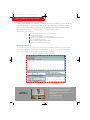
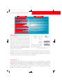
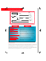
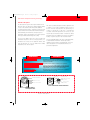
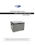
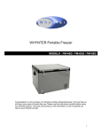
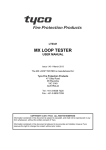
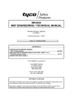
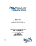
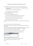
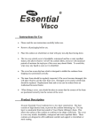
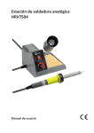
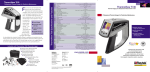
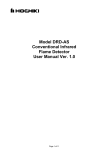
usethisnewPSF111U.QXD
28/3/02
11:08 pm
Page 3
Minerva
FIRELINE
Applications
•
MXF100 Optical
Fibre Temperature
Sensing Technology
Power Stations
MoD Property
Road and Rail Tunnels
Mass Transit Railway Systems
Petrochemical and Oil Terminals
Airport Terminals and Hangars
Process Plants, Distilleries, Escalators
Roof Tanks, Warehouses and Cold Stores
Cable and Utility Tunnels
Data Processing Centres
Parking Garages
Conveyer Belts
Offshore
•
The Minerva Fireline MFX100 is a revolutionary laser and fibre optic based Linear Heat Detection system providing
a fast, flexible and highly resilient means of detecting fires and protecting both people and plants in a wide variety
of risks. The technology is well proven and has already been specified and successfully installed in many different
applications.
usethisnewPSF111U.QXD
28/3/02
11:09 pm
Page 4
Optical Fibre Temperature Sensing Technology
Introduction
The Minerva Fireline MXF100 uses a combination of powerful laser technology and computer processing to provide fast
and accurate temperature measurement along a 2 Km loop of fibre optic cable. Precise fire and sensor cable break
detection can be determined within an accuracy of 1.25m. The MXF100 provides a flexible programmable platform to
suit many different risks and can be easily integrated into the overall fire protection systems.
The main features of the system are:
Automatic detection and full recovery from sensor cable break
Safe (Class 3A) laser operation
Continuous ‘live’ assessment of the development of fires
Wide range of programmable temperature operating modes and alarm thresholds
Up to 100 programmable alarm zones
Unaffected by Electromagnetic Interference (EMI)
Suitable for use in designated Hazardous Areas
MXF Manager Software
The MXF Manager (Windows) software is used as an interface to the MXF100 control unit. By using this software,
it is possible to configure the MXF100 unit to suit the particular fire risk. The system is password protected and
can be set up to provide a continuous display of system status on a dedicated PC.
Figure 1. Temperature Profile & Alarm Display
Figure 1 Illustrates the temperature profile display for the entire fibre length and also a numerical display for individual zonal temperatures.
Summary of
Cable Features
.
.
.
.
.
Low thermal mass for rapid response to temperature
Low smoke halogen free jacket, with excellent flame
retardancy. Suitable for all indoor applications
Stainless steel clad fibre optic cable suitable for all harsh
area applications
Strong, lightweight and flexible
Designed for ease of installation
usethisnewPSF111U.QXD
28/3/02
11:09 pm
Page 5
Optical Fibre Temperature Sensing Technology
BENEFITS
FEATURES
D IR E C T P C C O NN E C TI O N
This enables a user to view the temperature profile for the risk. It also provides an interface to allow adjustment of the alarm trip levels - this is access
level protected.
C O NT IN U O U S T E M P E R A T U RE
P R O F I LE S
By connecting a PC, it is possible to monitor the entire sensing cable length
to view the current stratus of the alarm system which assists in easily determining the proximity to an alarm state.
P R O G R A M M AB L E N U M B E R
A N D L E N G TH O F F I R E
D E T E CT I O N Z O N E S
A singe cable length can be divided into multiple fire detection zones thereby giving increased system flexibility whilst keeping cable lengths to a minimum.
V AR I A B L E R A T E O F R I S E A N D
F I X E D T E M P E R AT U R E F U N C T I O N
Variable rate of rise and fixed temperature alarm levels, ensure a flexible
heat detector sensitivity which can be tailor made to give an early warning
signal, dependant on the fire risk.
M U LT IP L E & P R O G R A M M A B L E
A L A R M L E V E L S PE R F I R E
D E T E C TI ON Z O N E
Pre- alarm warnings can be given, prior to a full alarm condition, thus helping to ensure minimal plant downtime.
U N R I V A LL E D R E S P O N S E T IM E
The sensing element is designed to respond very quickly to changes in
ambient temperature thus ensuring an early warning heat detection system.
MXF100 Control Unit
Alarm information is obtained quickly from the powerful and
Pulsed
Laser
intelligent MXF100 processor. The control unit uses a laser
light source to launch light signals into the optical fibre.
Please refer to fig.2 for Operating Principal diagram. As
pulses travel down the fibre , energy is lost t hrough
Signal
Processing
scattering. A fraction of the scattered signal is retained
within the fibre. A portion of this is directed back along the
fibre towards the laser source - this signal is called back-
Signal
Processing
Data
Acquisition
Optical
Receiver
scatter. Part of the back-scatter signal (Raman Scattering) is
used to provide accurate remote temperature measurements
Fig. 2 MXF100 Operating Principle
at hundreds of points along the fibre.
The MXF100 control unit is housed in a robust wall mounted cabinet with a style and livery matching that of the latest range of
Minerva MX control panels. it contains the MXF100 sensor cable analyser and provides local alarm and fault indications, a
PSM800 4A power supply module, field terminals for connection to signalling relays and a termination box for the fibre optic
splice joints to the sensing cable. It requires externally mounted standby batteries.
System Architecture
The MXF100 provides output options, which operate concurrently to provide system design flexibility. 22 programmable
relays can be used to map out alarm zones into a fire panel, either directly or via addressable interface modules such as the
MX CIM800. Protocol definition data is given to enable the MXF100 to be connected via a PLC to a centralised control and
monitor information centre, e.g. SCADA. Definition for a bespoke MXF protocol is also available to enable the development of
alternative graphics display interfaces. The full 200-zone capability of the system can be exploited using either the Modbus
and MXF protocols. Figure 3 shows typical system architecture.
usethisnewPSF111U.QXD
28/3/02
11:09 pm
Page 6
.
Optical Fibre Temperature Sensing Technology
USER
Sensor Cable
MXF100
MXF Protocol
~
PSU
24V
Remote PC
Modbus
PLC
SCADA
Relays
ADDRESSABLE
RELAY INTERFACES
FIRE ALARM
PANEL
Fig. 3 Minerva Fireline MXF100 Typical System Layout
BENEFITS
FEATURES
F I B R E O P T I C S E N S O R L O O P Very long distance (large areas) can be monitored using a single length of heat
sensing cable. The hot spot identification on a 2 Km length of fibre optic sensing
U P TO 2 K m
cable, is to within 1.25metres.
P ROG R AMM ABL E RE L AY
CO NT AC TS
22 zonal relays ensure that the system can provide sufficient alarm notifications –
typically directly to any Fire Alarm Control Panel. 2 relay contacts are reserved for
system and sensor fault.
MOD BU S O UTP UT PO RT
Permits connection of the system to any PLC (programmable logic controller) or DCS
(distributed control system) using industry standard communications, thereby
providing a very flexible system topology.
H I G H S Y S T E M I N T E G RI TY
The system can be set to operate in either single ended or loop mode without any
additional costly hardware. The system continuously monitors the integrity of the
loop and continues to operate in the event of a cable fault. The system is designed
with an automatic loop break recovery operation.
AUT O M ATIC FA ILUR E MO DE
A NA LY SI S
Cable faults are detected to an accuracy of ±1.25m. The control system is
continuously monitoring and a full syntax of fault information is provided with the
system.
S AFE L ASE R SO UR C E
In the event of a cable failure, where the laser light source may be exposed, the laser
light is determined a safe source in accordance with IEC825.
D I A GN O S T I C C A P A B I L I T Y
Enables interrogation of the system to determine system status.
M OD EM INT ER FA CE
By using a remote PC with a dial up connection to the host PC on site, it is
possible for system to be accessed from a remote location to help assist with
on-line technical support.
The Optical Fibre Sensor
The MXF100 uses standard communications grade optical fibre of the 62.5/125 graded index multimode type. The temperature range
is predominantly a function of the coating used to protect the optical fibre as the fibre itself is well behaved over a temperature range
from -50ºC to approximately 300ºC. Coatings have been tested down to -190ºC (acrylate) and up to 460ºC (metallic).
Optical fibre itself offers several advantages as a sensing medium. The signals are immune to electromagnetic interference thereby
ensuring integrity of readings from electrically noisy areas. As no electrical current is used in the sensing fibre and the fibre is a
relatively inert and dielectric (non-conducting) medium, it is safe technology to use in hazardous environments.
usethisnewPSF111U.QXD
28/3/02
11:08 pm
Page 1
Optical Fibre Temperature Sensing Technology
MXF100 Cable Options
The fibre used in this system is based upon standard 62.5/125
fibre optic cable. The cable has been further modified by adding
This cable is specifically designed for all indoor applications and
is suitable for some outdoor installations. When used out of
a choice of two external sheaths which provide additional
mechanical strength to the fibre. Gel filled loose tube technology
protects the fibre from mechanical and environmental damage,
doors it should be suspended above the ground using, for
example, a catenary wire or cable tray. It will withstand
occasional contacts with hydrocarbons such as kerosene, but
whilst maintaining a low thermal mass for rapid response to
temperature changes. This temperature sensor cable is jacketed
long term exposure should be avoided. It should not be directly
buried in the ground or installed in ducts that are susceptible to
with a special flame retardant halogen free coating.
flooding. Long term exposure to water should be avoided.
The Sensor Line MXF-SL fibre optic cable is designed for
distributed temperature and fire sensing applications, It is
intended for use in areas such as equipment cabinets, cable
trays, dry cable ducts etc, ie in any situation where a flexible
temperature sensor cable is required.
The SensorTube MXF-SS fibre optic cable, is particularly suitable
for harsh industrial environments. The fibre optic cable is
supplied encased in a stainless steel capillary tube. This sensor
cable is designed for use in heavy industrial, offshore and
petrochemical applications.
BENEFITS
FEATURES
I NS E N S I T I V E T O E M I
This allows the sensing cable to be installed in areas with high levels of
electrical and magnetic fields without any risk of unwanted alarms due
to interference from EMI.
I N T R I N S I C A L LY S A FE SE N SO R
The sensing element is suitable for hazardous area applications.
U S ES ST A N D AR D G RA D E
C O M M U N I C A T I O N F IB RE
Some application areas may require relatively long transit cable runs.
These transit cables can be any suitable and appropriate communications grad optical fibre (62.5/125). Additionally, existing fibres have
a quoted lifetime of 30 years, and no associated maintenance.
C H O I CE O F C A B L E
C O N ST R U C T I O N
The sensing cable comes in a variety of different forms to provide a
cost effective solution for the fire risk.
Stainless tube
PVC Sheath φ 0.25mm
Optical fibre in gel filled tube
Cladding of optical fibre
φ 0.125mm
Aramid fibres for strength
Outer jacket 3.6mm diameter
3.2mm
Optical
Fibre
Core of optical fibre
φ 0.0625mm
Sensor Tube MXF-SS Stainless Steel Cable
4.2mm
SensorLine MXF-SL
Thermoplastic Cable
Figure 4. Cable Options
usethisnewPSF111U.QXD
28/3/02
11:08 pm
Page 2
Optical Fibre Temperature Sensing Technology
Standards and Approvals
LPCB (submitted)
The MXF100 system complies with:
..
EMC Directive 89/336/EEC
Low Voltage Directive 72/2/EEC
The MXF100 contains a Class 3a Laser product
and complies with:
..
.
BS7192 (1989)
American National Standard Z136.2 (1988)
International Electrotechnical Commission
Standard 825 (1990)
Technical Information
Product Code
516.016.111
MXF100 Control Unit
Mechanical
Dimensions(mm)
Weight
Electrical
Supply Voltage
18-32 Vdc.
Power Consumption
25W max
Supply Current
<1A
Fuse Rating
<2A (anti-surge)
558.8 (W) x 587.4 (H) x 119.1(D)
28 Kg
Interface Options
2 off RS232 Ports
Port 1: Direct PC Connection for continuous
temperature profile displays (MXF protocol)
Port 2: Modbus master port or future
connection to FSI
Relay Outputs
22 Programmable outputs - SPDT 1A @24V dc
Environmental
Temperature
Operating:
Storage
Humidity
0˚C to 40˚C
(Note*)
-40˚C to 65˚C
0 to 95% RH (non condensing)
Electromagnetic Compatibility (EMC)
Assessed for Immunity to: EN 50082-1 and EN 50130-4
Assessed for Emissions to: EN 50081-1
For more information on this product
please refer to the following manuals:
User Manual 120-415-55
Engineering manual EM14
Fibre Optic Cable
Product Code
Operating Temperature
MXF-SL Thermoplastic
MXF- SS -Stainless Steel
516.016.112
516.016.113
-20°C to 70°C
-40°C to 90°C
Range of cable mounting accessories - see User Manual
* Note: Can be operated outside this temperature range using IP66
enclosure with thermal management unit.
The right is reserved to modify or withdraw any product or service without notice
Technical Information Sheet PSF111U Issue 2
www.tepg.com
©Thorn Security Ltd. 2000