1
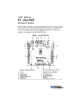
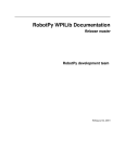
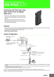
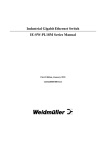
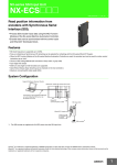
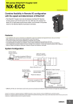
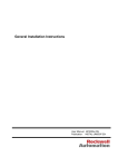
PDP User’s Guide
1/22/2015
Power Distribution Panel
User’s Guide
Rev 1.2
Cross The Road Electronics
www.crosstheroadelectronics.com
Cross The Road Electronics
Page 1
1/22/2015
PDP User’s Guide
1/22/2015
Table of Contents
1. Power Distribution Panel at a Glance ..................................................................................... 3
1.1. Connection Specifications ............................................................................................... 4
1.2. Electrical Specifications ................................................................................................... 5
1.3. Mechanical Specifications ............................................................................................... 5
1.4. Communication Specifications ......................................................................................... 5
2. Installing a PDP ..................................................................................................................... 6
2.1. Battery harness ............................................................................................................... 6
2.2. Breakers .......................................................................................................................... 7
2.2.1. Snap Action 40 Amp Breaker .................................................................................... 7
2.2.2. Snap Action 20/30 Amp Breaker ............................................................................... 8
2.3. Weidmuller Connectors ................................................................................................... 9
2.3.1. roboRIO, PCM, VRM ................................................................................................10
2.3.2. CAN bus ..................................................................................................................11
2.4. Blade Fuse Replacements ..............................................................................................12
3. LED States ............................................................................................................................13
4. Functional Limitations (software) ...........................................................................................14
4.1. Firmware <1.40: If Robot Is Enabled/Disabled/Enabled Quickly, FRC robot may
momentarily disable...............................................................................................................14
4.2. Firmware <1.40: Power and Energy ...............................................................................14
4.3. LabVIEW: Energy signal is not scaled to Joules. ............................................................14
4.4. C++/Java: Energy signal is in Millijoules. ........................................................................14
4.5. Firmware <1.37: Current may read ~2A when there is no current. ..................................14
5. Revision History ....................................................................................................................15
Cross The Road Electronics
Page 2
1/22/2015
PDP User’s Guide
1/22/2015
1. Power Distribution Panel at a Glance
Cross The Road Electronics
Page 3
1/22/2015
PDP User’s Guide
1/22/2015
1.1. Connection Specifications
● Battery
○ Bushings Lugs x 2
○ Thread M6x1 (10mm Length)
● Power Channels (All Channels provide battery power)
○ WAGO Connectors
■ 8 Red Channels 4-11
● 30 Amp
■ 8 Red Channels 0-3, 12-15
● 40 Amp
■ Black terminals are common
○ 6 Position Weidmuller Connector
■ PCM, VRM Supply
● 20 Amp fused (ATM blade mini fuse)
■ roboRIO Supply
● 10 Amp fused (ATM blade mini fuse)
■ Max: 16 AWG
■ Min: 24 AWG
See Section 2.3. Weidmuller Connectors for wire insert instructions.
● CAN
○ 4 Position Weidmueller Connector
■ Yellow CAN High x 2
■ Green CAN Low x 2
Cross The Road Electronics
Page 4
1/22/2015
PDP User’s Guide
1/22/2015
1.2. Electrical Specifications
Input Voltage (Vbat)
5.5-16 V
Absolute Max Input Voltage(1)
0 - 20 V
Output Voltage
●
Channels 0-3, 12-15
Vbat - 40 A
●
Channels 4-11
Vbat - 20 or 30 A
●
VRM, PCM Weidmuller
Vbat - 20 A fused
●
Controller Weidmuller
Vbat - 10 A fused
Note 1: Stresses above those listed under “Absolute Maximum Ratings” may cause permanent damage to the device. This is a
stress rating only and functional operation of the device at those or any other conditions above those indicated in the operation
listings of this specification is not implied. Exposure to maximum rating conditions for extended periods may affect device reliability.
1.3. Mechanical Specifications
Length
7.586 in.
Width
4.748 in.
Height
1.422 in.
Weight
1 lb. 5.3 oz.
1.4. Communication Specifications
Baud Rate
1 MB/s
CAN Termination
120 Ohm (jumper placed in the ON position).
None (jumper missing or placed in the OFF
position).
CAN High / Low
Cross The Road Electronics
2 Ports
Page 5
1/22/2015
PDP User’s Guide
1/22/2015
2. Installing a PDP
2.1. Battery harness
● Components
○ QTY 2 - M6x1 Bolts (10mm Length) Socket Head Cap Screws
○ QTY 2 - 6mm Split (Lock) Washers
○ Battery Cover
■ QTY 2 - 6-32 (1/2” Length) Battery Cover Flat-Head Socket Cap Screw
○ 12 Volt Supply (Battery, Power Supply, etc...)
Warning: Do not reverse the battery voltage as this can cause permanent damage to
current sense circuitry. Additionally the FRC Control System Components that draw
power from PDP may not have reverse battery protection, and can also be damaged in a
reverse battery event.
Cross The Road Electronics
Page 6
1/22/2015
PDP User’s Guide
1/22/2015
2.2. Breakers
2.2.1. Snap Action 40 Amp Breaker
● Channels 0-3, Channels 12-15
○ 40 Amp Breaker
○ Limits Closest Red WAGO
○ Supplies Battery Power
Warning: Inductive loads (motor, compressor) must have a power management device (motor
controller, PCM, spike) between itself and the PDP. No inductive loads (motor, compressor)
may be directly connected to the PDP channels as this can damage current sense circuitry.
Cross The Road Electronics
Page 7
1/22/2015
PDP User’s Guide
1/22/2015
2.2.2. Snap Action 20/30 Amp Breaker
● Channels 4-11
○ 30 or 20 Amp Breaker
○ Limits Closest Red WAGO
○ Supplies Battery Power
Warning: Inductive loads (motor, compressor) must have a power management device (motor
controller, PCM, spike) between itself and the PDP. No inductive loads (motor, compressor)
may be directly connected to the PDP channels as this can damage current sense circuitry.
Cross The Road Electronics
Page 8
1/22/2015
PDP User’s Guide
1/22/2015
2.3. Weidmuller Connectors
Wire Insertion
● Disconnect PDP from Battery before adding or modifying connections
● Strip wire back ~0.375” (3/8”)
● Press and hold down connector button. Though this isn’t necessary, it ensures the
stripped wire does not deform and split into “whiskers” after excessive use. A small
screwdriver can be used to easily hold down the connector button.
● Insert wire into connector opening
● Release connector button
● Pull wire to ensure wire is locked in connector
● Confirm wire strands are not extruded
Wire Inspection
● Verify that there are no “whiskers” outside of the connector that may cause a short.
● Verify that the stripped portion of the wire is not excessive enough to cause a short.
● Tug on the wire and verify wire does not pull out. If it does then recheck gauge and/or
strip the wire back further.
Wire Removal
● Press and hold down connector button immediately above connector opening
● Pull wire to remove from connector
Limitations
● Wire should not be frayed upon insertion. Extruded wire may short to adjacent
channels.
● Wire should be no larger than 16 AWG, larger gauges will not properly fit in connector
● Wire should be no smaller than 24 AWG, smaller gauges will not lock in connector
Cross The Road Electronics
Page 9
1/22/2015
PDP User’s Guide
1/22/2015
2.3.1. roboRIO, PCM, VRM
Weidmuller Connectors are used for connecting the roboRIO, PCM, and VRM modules to
power. See Section 2.3. Weidmuller Connectors for wire insertion and removal procedures.
See Section 2.4. Blade Fuse Replacements for fuse details.
Cross The Road Electronics
Page 10
1/22/2015
PDP User’s Guide
1/22/2015
2.3.2. CAN bus
Weidmuller Connectors are also used for CAN Communication. See Section 2.3. Weidmuller
Connectors for wire insertion and removal procedures. Smart Module provides termination
and may be placed at the end of CAN bus chain.
Termination Resistor Jumper
- Only place the jumper to the ON position when PDP is at the end of the CAN bus.
- ON State - Positioning the jumper closest to the inside of the PDP (shown above).
- OFF State - Positioning the jumper closest to the edge of the PDP or removing the jumper.
Cross The Road Electronics
Page 11
1/22/2015
PDP User’s Guide
1/22/2015
2.4. Blade Fuse Replacements
Both automotive fuses are type ATM automotive blade mini fuses. Spares can be purchased at
most hardware stores (Do not purchase ATC as they will not fit).
Example replacement purchase for 10A Controller fuse
Cross The Road Electronics
Page 12
1/22/2015
PDP User’s Guide
1/22/2015
3. LED States
The STAT and COMM LEDs are multi-color LEDs that can blink green, orange, or red.
The two LEDs are always the same color/blink pattern. The only exception to this is when the
device is in boot-loader.
Cross The Road Electronics
Page 13
1/22/2015
PDP User’s Guide
1/22/2015
4. Functional Limitations (software)
Functional Limitations describe behavior that deviates from what is documented. Feature
additions and improvements are always possible thanks to the field-upgrade features of the
PDP.
4.1. Firmware <1.40: If Robot Is Enabled/Disabled/Enabled Quickly, FRC
robot may momentarily disable.
When PDP is wired to roboRIO’s CAN bus and robot enters disabled state, roboRIO typically
begins extracting logged records from PDP. However if robot is immediately enabled after
initially entering disable, the roboRIO may very briefly disable as it finishes extracting PDP logs
despite being enabled in the Driver Station.
This occasionally causes motor-drive to briefly disable once after enabling robot. Additionally
the fault count will increment in the Driver Station (lightening tab).
Issue is fixed in PDP Firmware 1.40. When PDP detects roboRIO is enabled it will abort
extraction, therefore preventing the problem condition from occurring.
4.2. Firmware <1.40: Power and Energy
Power and energy signals were not computed correctly in firmware versions earlier than 1.40.
Updating to 1.40 will ensure Power and Energy signals are updated correctly.
4.3. LabVIEW: Energy signal is not scaled to Joules.
The Energy signal in LabVIEW is computed in engineering units where each unit is 0.020
Joules. Multiply the signal value by 0.020 to scale to Joules.
4.4. C++/Java: Energy signal is in Millijoules.
The Energy signal in C++/Java is computed in units where each unit is 0.001 Joules. Multiply
the signal value by 0.001 to scale to Joules. If using this signal for robot-processing, be sure to
check for the fix whenever updating C++/Java libraries.
4.5. Firmware <1.37: Current may read ~2A when there is no current.
The current sense circuitry has biasing (similar to a gyro). Firmware 1.37 and on will zero the
output so that 0A is read when there is no load.
Cross The Road Electronics
Page 14
1/22/2015
PDP User’s Guide
1/22/2015
5. Revision History
Rev
Date
Description
1.2
22-Jan-15
Moved Section 4 to Section 5.
Added Section 4 Functional Limitations.
1.1
19-Jan-15
Added Section 2.4 for fuse replacements
Added screw length details in Section 2.1
Warnings Added in Section 2.2 for inductive loads.
1.0
30-Dec-14
Initial Creation
Cross The Road Electronics
Page 15
1/22/2015