1
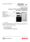
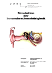
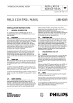
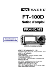
INSTALLATION
INSTRUCTIONS
DP 6000 DIGITAL PAGING SYSTEM
63
December 1997 Page 1 of 28
High Performance Control Desk
Medium Performance Control Desk
Medium Performance Control Desk
LBB 5800/00
LBB 5801/00
LBB 5802/00
1. GENERAL INFORMATION
2.1.
1.1.
Ensure that all packing debris has been removed from the desk and
that there is no sign of any obvious damage.
Description
NOTE: THIS INSTALLATION INSTRUCTION IS APPLICABLE TO
SOFTWARE VERSION 1.0, CHECKSUM
2 F 7 A AND SOFTWARE VERSION 2.0, CHECKSUM 13 4 B
The Philips DP 6000 Digital Paging System, when installed, will
provide an effective communication system between one or more
fixed control points and personnel on the move around the
customers premises.
Each participant has a personal pocket receiver which is tuned to
the operating frequency of the system. The receivers are individually
identified by the allocation of call numbers, which are programmed
into the receiver and each receiver will only respond to calls made
specifically to its own call numbers or to a group call (this is a single
call sent from the desk which can be received by more than one
receiver holder) in which the receiver is included.
Preparation
The desk should be set for three wire operation, to change to four
wire operation proceed as follows:
1. Locate and remove the four cross headed screws at the base of
the unit
2. Place the desk on a flat surface in the normal operating position
3. Open the desk as shown at operations 1, 2 and 3 of figure 1.
The High Performance Desk (LBB 5800) with software version 2.0
can also be used in PS 6000 Paging Systems, for information on this
refer to the User Manual and Installation Instruction for the LBB
6005.
The desk can be programmed to provide all the functions described,
however limitations can be imposed on these depending on the
receivers used in the system e.g. the LBB 6080 receiver will only
respond with bleeping signals and will not respond to any other
transmitted information including speech.
2. INSTALLATION
This Installation Instruction describes all the programmable
functions of the High Performance Control Desk (LBB 5800). The
Medium Performance Control Desks (LBB 5801 and LBB 5802) do
not have all of the features of the LBB 5800 but are installed in
exactly the same way. For details of the various features available on
each type of desk, refer to the third column of TABLE 2. (page 29).
3
Philips
Communication &
Security Systems
DP 6000 DIGITAL PAGING SYSTEM
INSTALLATION INSTRUCTION 63
December 1997
Page 2/28
2.2. Jumpers
2.4.1 Direct Coding
Figure 2 shows the location of the jumpers which are used to set
the desk for three or four wire operation.
This means that an external alarm call is made by connecting one of
pins 9 - 16 to earth (PIN 4). With LBB 5800 it is possible to connect
8 external alarm calls (pins 9 - 16 are connected to earth). With
LBB 5801 and LBB 5802, only four external alarm calls can be used
(pins 9 - 12 are connected to earth and pins 13 - 16 are not used).
In this mode, more than one call can be initiated simultaneously.
Ensure that the jumpers are set to the positions for the system to
be installed.(factory set for three wire system).
When this is complete, close the desk by carrying out the reverse
procedure at Figure 1.
2.3. Connection To The System
The desk is connected to the DP 6000 Paging System via a 16 pole
Hirschmann plug. For details of the system wiring, refer to Figure 3
and Table 1 (Page 19).
2.4. External Alarm Connections
Figure 3 shows the method of connecting the remote
alarm contacts. The number of calls that can be used
depends on the type of desk and the type of coding at the
input to the desk (16 pole Hirschmann plug). There are
two methods of coding these calls as follows:
2.4.2 Binary Coded Calls
If this facility is programmed, 15 external alarm calls can be
connected (this applies to all three desks). Connecting pins 9 - 12 to
earth are used together as binary coded inputs for an external alarm
call.This is achieved as follows: if pin 9 is connected to earth;
external alarm call No. 1 will be transmitted - if pin 10 is connected
to earth ; external alarm No. 2 will be transmited - if pins 9 and 10
are connected to earth; external alarm No. 3 will be transmitted
etc. If this facility is programmed, only one alarm call can be
transmitted at a time.
NOTE: The remote external alarm contacts must be VOLTAGE
FREE. Never use contacts on any piece of equipment which carries
or is likely to carry any voltages. Also keep them away from the
system wiring.
OVERVIEW OF ALL EXTERNAL ALARM CALL CONNECTIONS
NOTE: The resistance of the wiring for
each contact must not exceed 100 kΩ
Pin of Hirschmann plug
connected to earth
DIRECT CODED
910111213141516
Call 1
Call 2
Call 3
Call 4
Call 5(LBB 5800 only)
Call 6(LBB 5800 only)
Call 7(LBB 5800 only)
Call 8(LBB 5800 only)
X
BINARY CODED
910111213141516
X
X
X X
X
X
X
X X
X X X
X
X
X
X
X
X
X X
X
X X
X X X
X X X X
Call 1
Call 2
Call 3
Call 4
Call 5(LBB 5800 only)
Call 6(LBB 5800 only)
Call 7(LBB 5800 only)
Call 8(LBB 5800 only)
Call 9
Call 10
Call 11
Call 12
Call 13
Call 14
Call 15
X
X
X
X
X
X
X
INSTALLATION INSTRUCTION 63
DP 6000 DIGITAL PAGING SYSTEM
Page 3/28
2..5 Handset
A handset (LBB 5804), which can be connected to the LBB 5800 or
LBB 5801 desks, is available as an optional extra (see figs. 5 and 6).
The handset comes complete with cradle and mounting screws for
connection to the side of the desk (see Fig 6.). If the handset is to
be fitted, the use of it must be enabled in the Editor Mode(see para.
11.5)
Electrical connection to the desk is via the 7 pole DIN socket at the
rear of the desk.
When this handset is resting on the cradle, the desk microphone
and speaker will operate in the normal way. When the handset is
removed from the cradle,the desk microphone and speaker are
automatically inhibited.
2.6..
Controls And Indications
The +12V supply for the desk is taken from the system power
supply unit via pins 4 and 8 of the 16 pole Hirschmann socket and
the green LED of the desk will be illuminated as soon as the
connection is made. The remaining controls and indicators are
shown at Figure 5.
3. FUNCTIONAL DESCRIPTION
December 1997
iv) The Address, and 11 digit info - The 11 digits are transmitted as
two calls: five digits of info, then another 5 digits of info +
Codinf (Codinf used as info and call tone not selectable) The
Codinf can only be used once as an info digit.
The complete call comprising (a, b and c) can be transmitted
automatically or manually depending on how the desk is
programmed.
3.2.
Mode of Operation (see para. 8.1.)
As can be seen at para. 8. 1 the desk can be programmed in one of
four different modes of operation. The programming of the call
string variables will be determined by which mode of operation is
entered e.g. the codinf digit should not be assigned to a speech call if
it is used as an information digit.
3.3.
Receiver Address (see para. 8.2.)
The control desk can be programmed to cater for systems with a
capacity of 10, 100, 1000, or 10,000 receivers which can be
individually paged. The number of receivers in the system will
determine the number of call number digits to be keyed into the
desk (maximum 4 digits = 10,000 receivers and the available call
numbers will be 0000 - 9999).
The following paragraphs 3.1 to 5.10 describe the programmable
functions of the control desk. Details of the Menus, Commands and
variables and how to enter them are given seperately in paragraphs
6 to 17.3.
If the system has, say 100 receivers two digits need be used ( 00 99). The remaining 2 digits can be programmed into the desk leaving
the operator to enter the other 2. In systems with 10 receivers the
operator need only enter 1 digit (0 - 9) and the remaining 3 digits
are pre-programmed.
Bear in mind that the LBB 5801 and LBB 5802 desks do not have all
of the functions described in the following paragraphs and reference
should be made to TABLE 2. for this information. The desk
workmode is set using Menu Key “E” Command 7. (see Para.7)
There are other combinations that may be pre-programmed e.g. if
you want the call numbers in the system to be linked to internal
telephone numbers, then it is possible to use four digits in a system
of say 75 receivers.
3.1
Programming Call String Variables
(see para. 8.)
The Call String is the information sent by the desk to a particular
receiver or group of receivers. The complete Call String comprises
the following:
a) The call number of the receiver to be paged (first four
digits).
b) One of the audible call tones shown at Fig. 4 which can be
allocated meanings to indicate the urgency or the nature of the
call and following information. (fifth digit)
c) 5 digits of information, which can be used to convey
telephone numbers etc. to receivers fitted with
display heads. (last five digits )
The desk can be programmed to transmit 5, 6, 10 or 11 digits of
information as follows:
i)
The Address, the Codinf (call tone selectable) and 5digit info.
ii) The Address and 6 digit info (5 digit + Codinf displayed on
receiver as info digit, and call tones are not selectable)
iii) The Address, the Codinf (call tone selectable ) and 10 digit info.
This info is transmitted as two calls. The receiver stores the first
5 digits in memory and adds them to the second call.
3.4
Codinf (see para. 8.2.)
The codinf digit is the fifth digit in the call string and can be
programmed to be fixed or selectable. The value of the codeinf can
be programmed to transmit one of the call tones shown at figure 4.
The call tone is an audible bleep heard at the called receiver. Up to
14 different patterns of call can be used, these are shown at Figure
4. The single call tone digit can be chosen by the operator and
manually keyed in after the address, or automatically preprogrammed into the desk.
The call tones that are shown as “Cricketed sounding” in Figure 4
can be selected by the operator if required, however the Group
Calls that are programmed into your system
always use the
“Cricketed sounding” tone patterns irrespective of the call tone that
is entered.
Another important use of the call tone digit is to allow the operator
to follow up the paging call with speech (see para. 3.15).
DP 6000 DIGITAL PAGING SYSTEM
INSTALLATION INSTRUCTION 63
December 1997
3.5.
Display Information.
( See para. 8.2 and 8.3)
If the system is equiped with receivers with a display head fitted,
information can be transmitted and this information will be
displayed on the LCD head of the receiver, thus allowing greater
communication possibilities, such as specific coded instructions or
telephone numbers
The system may have two types of display receivers i.e. a 5
character display or a 6- character display ( call tone digit + 5
information digits).
With the 5 digit version, a message of up to 10 characters may be
sent to that receiver, five of which will be displayed and five held in
the receiver memory.
Receivers with 6 character displays can accept a message of max. 11
characters. The receiver will show the call tone digit + 5 characters
and retain another 5 characters in the memory.The call tone digit is
only displayed once.
The sequence and number of receiver display characters can be
arranged by programming fixed digits to suit the customers
particular requirements when the desk is programmed. If, for
example, you only require to transmit telephone numbers of not
more than 3 characters, then 2 digits can be pre-programmed and
only three need be entered via the desk keyboard.
3.6
Automatically Transmitted Codeinf +Display
Info. (see para. 8.4)
If codeinf and display information are selectable, after entering the
call number digits, the desk responds with the codeinf selection
tone(2sec. duration) and after that, a 2 sec. duration tone for the
selection of display information. If during these two periods, no
selection is made, the desk will transmit automatically, the
information programmed at para. 8.4.
If your only requirement is for the receiver holder to call the
operator, then the desk could be pre-programmed with the
operators telephone number.
3.7.
Automatic or Manual Transmission
(see para. 8.5 )
After all the digits needed to make up a call have been entered via
the keyboard, the call can be transmitted by pressing the CALL
TRANSMIT key or the desk can be programmed for automatic
transmission, then the call will be transmitted as soon as the last
digit of the call is entered.
Irrespective of how the call is first transmitted, the last call displayed
in the desk display window can be retransmitted each time the
CALL TRANSMIT key is pressed. This can be done until the RESET
key is pressed . When this is done the message will be cleared from
the display window and the real time will reappear in the display.
This applies to the LBB 5800 only if the clock has been enabled, the
LBB 5801 and LBB 5802 display will be blank.
3.8.
Sequencing (see para. 8.6 and 8.7 )
If sequencing is enabled, the call string must be transmitted twice
per transmitter, therefore the number of transmitters used in the
system is the number of call strings set at Command 7 divided by
Page 4/28
two. It is obvious therefore that the number of call strings
programmed must be even.
If sequencing plus 10 digit calls are both programmed, each call will
take two complete sequences. The first sequence will consist of a
silent call containing the last five digits of info which is stored in the
receiver memory.The second sequence will consist of the call tone
and the first five digits of the message which will be displayed on the
receiver display.
When sequencing is enabled, the desk will not interupt the line with
non-speech calls if the line is occupied on speech or priority level.
This also applies to alarm calls.
3.9.
Battery Saving (see paras. 8.8 to 8.12)
There are three types of battery saving modes mentioned in the
programming instructions, Dynamic, Static and Universal. The
Dynamic mode can be ignored as this is for future generation
receivers.
The type of receivers in the system determine which battery saving
mode can be programmed.
Universal battery saving supercedes the Static mode and is
applicable to the standard receivers types LBB 5880 and LBB 5886.
In the Universal mode of operation, the receiver takes a shorter
time in detecting the preamble string and therefore has a better
battery saving mode ratio.
The number of preambles programmed at Command “A” also
determines the length of the 5F string preamble at the universal
battery saving mode and this should normally be 9 or greater.
The codeinf of the battery saving preamble can be used if the Static
battery saving mode is programmed, to separate two neighbouring
systems which are using the same frequency.
Only receivers which are programmed to the same preamble
codeinf will respond to a call.
3.10
Out of Range Indication (see para. 8.13)
When this facility is programmed, the desk will generate and
transmit a call every 30 seconds. As long as the receiver detects
this signal, it is within transmitting range of the system. If the signal is
not detected twice, the receiver will give an indication that it is out
of range of the transmitter and can not receive calls. Refer to the
receiver installation instructions to determine if the receivers in the
system have this facility, what type of out of range indication they
will give and the action to be taken by the user.
If the system is using VHF receivers with software version 4 or UHF
receivers with software version 1, the battery saving will be active
when these receivers are out of range. This means that the desk will
transmit the number of battery saving preambles programmed with
the out of range call irrespective of whether battery saving has been
inhibited or enabled (in this case , the Static mode of operation
should be programmed)..
3.11
Time Call (see para. 8.14)
If the real time clock is enabled in the LBB 5800 desk, a time call can
also be enabled. If this facility is enabled, the desk will transmit a call
to all receivers with the first two info digits representing hours and
the last two digits minutes of the real time. This call will be repeated
every time the minute digit changes. If the receiver has been
programmed for a particular time call, then that receiver will
respond when the time transmitted from the desk coorresponds to
that in the receiver memory.
INSTALLATION INSTRUCTION 63
DP 6000 DIGITAL PAGING SYSTEM
Page 5/28
3.12.
Speech Processing (see paras. 9 and 10.)
There are 7 commands available to programm the speech functions
and 3 Commands to set speech and talk through priority.
3.13
Speech Mode (see para. 9.1)
There are several methods of transmitting speech, any one of which
can be pre-programmed into the desk. Speech calls described at a)
and b) can be transmitted either automatically or manually and may
be dependant on the call tone digit Speech calls c) and d) can only
be manually transmitted.
As long as the microphone is switched on, the desk will emit a
series of short ticks (programmable on or silent see para.9.7). At
about 5 seconds before the end of speech time the two short
bleeps will be emitted. When speech is ended at the end of the
speech time, a tone the same as the error bleep will sound.
a) Manual speech after a call - The call is entered in the normal
way and transmitted. A wobble tone will be heard at the desk
while the receiver is bleeping. When the wobble tone stops the
desk emits two short high tones to indicate that speech can
begin, the operator can speak to the receiver holder by pressing
the TALK key The microphone is activated by the TALK key.
The speech time can be extended by pressing the TALK key
again within 1 second after releasing it, if this facility is
programmed.
b) Auto speech after a call - After the last info. digit has been
entered the call can be transmitted and the desk will go into the
speech mode. The operator can then speak, after the two
tones, without pressing any keys. In this mode, if the TALK key
is pressed and held, the system will revert to manual speech and
the speech will end on releasing the TALK key. In auto speech
mode, the microphone is automatically activated at the end of
the start speech tones. If speech time extension is programmed,
then you can extend the speech time on this call by the pressing
the TALK key and holding it down and this will give another
predetermined speech time of the same duration, which is
programmed.If the TALK key is released during the speech
extension time, this will end the conversation.
c) Manual speech linked to the TALK KEY -This facility gives the
operator a choice of transmitting a speech or non-speech call
depending on which key is used to activate the “wobble tone”. If
a speech call is transmitted by the TALK key, and the desk is
programmed for manual speech transmission , the desk
operator must press the TALK key again after the wobble tone
to activate the desk microphone.
d) Auto speech linked to the TALK key - If this facility is
programmed the operator can chose to send a speech or nonspeech call, but in this case, after the wobble tone, the desk
microphone comes on automatically and the operator can speak
to the receiver holder without touching any keys. To finish the
conversation the RESET key is pressed. At the end of the
programmed speech time, the desk will reset automatically.
While the microphone is on, a call to a second receiver (e.g. for
talk through) should be transmitted by the CALL TRANSMIT
key.
e) Manual speech without a preceding call - If a receiver holder
calls the desk, the operator can speak back to the receiver
holder by pressing the TALK key only.
December 1997
3.14
Speech Time Limit (see para. 9.2)
This desk can be pre-programmed to allow a spoken message of
between 10 and 254 seconds (programmable), or an infinite speech
time which can be terminated by pressing the RESET KEY, to be
transmitted to receivers equipped to receive the audio signal.
3.15
Speech Linked To Codeinf (see para. 9.3)
Another important use of the codeinf digit is to allow the operator
to follow up the paging call with speech. Any one of the call tones
,shown at figure 4 , can be pre-programmed to enable the speech
mode and this digit when entered in the call either automatically or
manually (programmable) will enable the operator to transmit a
spoken message.
3.16
Reset Speech Calls (see para. 9.4)
When enabled in the editor mode, this call will be transmitted
automatically at the end of a speech call or when the operator
presses the reset key during a speech call. The call will be
transmitted with codeinf “F” and 5xF info.digits.This call will switch
the receiver off to stand-by mode.
3.17
Speech Extension Calls (see para. 9.5)
A “speech time extension” may be pre-programmed which allows
the operator to extend the programmed speech time by pressing
the TALK key whilst the desk is still in the speech mode.This will
give the operator another period of speech time of the same preprogrammed duration as the initial speech time.This action can only
be done once.
3.18
Timer Count Down (see para. 9.6)
The speech time can be programmed to be counted only when
speech is transmitted from the desk or when speech is transmitted
from the desk together with the time that speech is received from
the talk back line.
3.19
Priority (see para. 10.)
There are 4 Commands to set the priority status of the desk, three
for speech calls and one to set the priority for a desk that is waiting
for a free line, compared to other encoders in the system.
The first Command enables or disables the use of the priority key. If
this key is enabled, the operator can get an immediate connection
to the system in the event that a speech call has to be transmitted
and the line is busy, providing that the call that is occupying the line
is not of a higher priority.
The second Commmand sets the level of a normal speech call to priority level or normal level. If the line level is set to priority level,
all speech calls will be transmitted as priority calls without having to
press the priority key. In this event, the priority key has no function.
The third Command in this Menu sets the level of the talk through.
If talk through is set to priority level and the desk is set to
automatic talk back and talk through, each speech call that is
occupying the line will be interrupted at the moment a transceiver
holder starts transmitting a signal.
The last Command sets the priority status in the event that if more
than one desk is waiting for a free line, the desk that is programmed
with the highest priority will take over first.
3.20
Tone Volume (see para.11.1)
The volume of the indication tones in the desk can be set to off or
to a desired level in the range (0 = off) to (7 max level). However
this only applies to desks LBB 5800 and LBB 5801. The volume of
the tones can not be altered in the LBB 5802.
DP 6000 DIGITAL PAGING SYSTEM
INSTALLATION INSTRUCTION 63
December 1997
3.21
Talk Back (see para. 11.2)
Page 6/28
to 13.11), however in these software versions of the desk, these
functions can not be used.
If the system is equipped with receivers fitted with a talkback
transmitter (the combined unit is called a transceiver) a two way
conversation can be carried out between the desk and the called
person. The reply speech from the transceiver is heard over the
desk built in speaker.
3.25
The call can be initiated by the desk to the transceiver or vica versa.
If the call is initiated by the transceiver holder, the desk will respond
with two high frequency tones and the red LED will illuminate. The
desk operator then uses the TALK key to reply, or when the desk
is programmed for automatic speech, the operator can speak
without pressing any keys.
The alarm call can be programmed to call a single receiver, group of
receivers or all receivers and speech can be linked to follow the
call. The data for this call is programmed with the same Menu and
Command key as for the remote contact calls
With LBB 5800 transceiver holders can choose one of two desks
to call using the two way selector switch on the transceiver. If the
call is initiated by the desk operator, the transceiver holder will have
to be told which desk is making the call. (para. 11.3)
The volume of the audio can be set, whilst the desk is not in the
Editor mode, by holding down the MONITOR key and selecting
one of the keyboard keys between 0 and 7. The OFF position is 0
and the loudest volume is 7.
3.22
Manual or Automatic Switching Of The Talk
Back Monitor (see para. 11.4)
The desk can be programmed such that when a transceiver holder
calls the desk, the talk back audio will automatically be heard with
no action by the operator or manually. In the latter case, when the
transceiver holder calls the desk, a “call desk” tone will be emited
from the desk and the operator has to press the Monitor key to
receive the audio and the display will show “field call”. If the Reset
key is pressed, the “call desk” tone will stop and the monitor will
not be switched on. The Call Desk tone will be emitted for 30
seconds max.
3.23
Talk Through (see para. 12)
When a speech call is made to a particular transceiver, the desk
operator can connect this tranceiver with any other transceiver
holder in the system. This is done by selecting the number of the
second transceiver and pressing the TALK THROUGH key.
Pressing the MONITOR key will allow the operator to hear the
conversation. If the operator wishes to join in the conversation,
pressing the TALK key will activate the desk microphone (this is
not necessary if the desk is programmed for auto speech). If the
operator does not want to join in the conversation, the RESET key
should be pressed. When a call has been initiated by a receiver
holder to the desk, the desk operator only has to press the TALK
key to reply.
The desk RED LED will be illuminated during the conversation
between the two transceivers ; when the conversation is over,
pressing the TALK THROUGH key again will reset the desk. The
desk will also reset automatically 9 seconds after the end of the
conversation or if there is no speech on the talk back line for this
time.
Alarm Calls (see para. 13)
An alarm call can be programmed into the desk. This alarm call can
be transmitted with a single keystroke by pressing the red ALARM
key and holding it down for at least one second.
3.26
Remote Contact Calls (see para.13)
Up to 8 remote contacts (switches) may be connected to the LBB
5800 desk ( up to 4 in the LBB5801 and LBB 5802). These contacts
may be connected to any piece of equipment that requires
monitoring. When one of these contacts is activated, a paging call
will be generated in the desk. The different ways to connect the
switches and the mode of operation is described at para 2.4. The
alarm call data is also programmed in this Menu.
Each alarm call can be programmed to transmit 5 or10 digit
information independant of the mode in which normal key calls are
made.
The desk can be pre-programmed to call a particular receiver or
group of receivers without any action by the operator. The call will
be repeated (repeat time programmable) as long as the remote
contact is activated.
Each remote contact call can be programmed to be followed by a
speech message. In this case, the desk will activate the speech
program which has been set in the speech menu. Speech after a
remote contact call is not dependant on the codeinf, if this facility
has been programmed for normal key board calls.
Decimal group call conversion facilities are also available on these
remote contact calls. This means that if a remote contact call is
transmitted to a receiver which is absent, the call will automatically
be sent to a group of receivers. If say Alarm contact No.1 is
programmed to call receiver address 1234 which is found absent,
the desk will call receiver addresses 123 - , in other words receivers
1230 to 1239.
3.27
Direct Calls (see para. 14.)
Up to 16 direct calls can be programmed into the desk. These calls
do not have to be keyed in via the keyboard, but are automatically
transmitted by pressing the DIRECT CALL key followed by
selecting the keyboard key that is programmed to the call that you
desire. A direct call can be made to page a single receiver holder, a
group of receivers, or all receivers depending on the preprogrammed call number.
Each direct call can be set to transmit 5 or 10 digits of information
irrespective of the mode in which normal key calls are made.
Speech can also be pre-programmed to follow a direct call.
The desk can also be programmed for automatic talk through,
where a transceiver holder can speak to another via the desk with
no action by the desk operator. In this mode, the audio signal will be
automatically transmitted via the paging line.
3.24
FIAC Calls
The Editor has been prepared for the programming of FIAC
functions at Commands 8 to B of the Alarm Key menu (paras. 13.8
3.28
Group Calls
The system can be set up to send a call to a group of receivers in
two different ways. This facility is described in Receiver
Programming at Paragraph 18.
INSTALLATION INSTRUCTION 63
DP 6000 DIGITAL PAGING SYSTEM
Page 7/28
3. 29
Real Time Clock (see para. 15)
December 1997
The LBB 5800 has a real time clock which shows the time on the
desk display when the desk is in the stand-by mode and the jumpers
are set to the correct position (see Fig. 2)
The desk will not accept a closed loop, when programming
conversions e.g. it is not possible to convert receiver
address “A” to receiver address “B”and then convert “B”
back to “A” again etc.
The clock settings are carried out in the Editor mode at Menu “C”
(see para. 15)
4.
It is also possible to adjust the clock when the desk is in the normal
mode as follows:
DESK LED INDICATORS
(SEE FIG. 5)
4.1
Green LED (3)
a) Press the Progam key and key “C” simultaneously
b) The desk display will indicate whether the clock is
enabled or inhibited
c) To disable the clock press KEY “0”
d) To alter the time pressKEY “1”
e) The display will indicate “HH - MM =” (hours and
minutes)
f) Key in the current time
g) When the last digit has been entered, the desk will
return to the normal operating mode automatically
3.30
Absence Indication
If your system includes receiver storage racks (such as LBB 5850),
the receiver holder will place the receiver in the rack when leaving
the premises. If the desk operator tries to call a receiver which is in
the rack, a signal will be sent back from the rack and an absence
tone (a high pitched 3 second tone)will be emited by the desk and
the red LED will flash, or if an absence conversion has been
programmed, the call will be transmitted to a second receiver.
The green LED is illuminated when the desk is connected to a
power supply. There is no power ON/OFF switch on the desk.
4.2
4.3
5.
3.31
5.2
If the second receiver is found absent, no second conversion will be
made and the desk will generate the absence signal.
OPERATION TONES
The following paragraphs describe the various tones
emited from the desk and the volume of these tones is
programmable. (LBB 5800 and LBB 5801 only see
para.11.1).
5.1
Absence Conversion (see para.16)
Yellow LED (5)
When a function has been activated the yellow LED will light. When
the desk completes the transmission of the call, the LED will be
extinguished.
If a group call is transmitted to a group of receivers, one or more of
which are in the storage rack, no absence indication will be given
and the call will be received by all other receivers in the group.
This desk has the possibility of an absence conversion table facility.
When a transmitted call is found absent ( the receiver is in the
storage rack) and the desk has been programmed with absence
conversion, it will retransmit the call automatically to a second
receiver. In this case the desk will not generate the absence signal.
Red LED (4)
The red LED will be illuminated when the paging line is occupied by
this, or any other piece of equipment in the system capable of
sending a paging call. When the paging line is occupied only certain
calls can be transmitted. (see para. 3.19)
Key Confirmation Signal
When entering any valid digit from the keyboard a single short
confirmation bleep will be heard.
Error Signal
When an incorrect entry is attempted, the desk will emit a series of
rapid short bleeps.
5.3
Acceptance Signal
After entering a valid call, the call acceptance tones will be heard (2
bleeps of 0.5 seconds) during which time all keystrokes will be
ignored.
5.4
Transmission Signal
This is a useful facility where , for instance, a consultant is on holiday
and his receiver is left in the storage rack and all calls made to him
have to be automatically diverted to his deputy.
The transmission signal consists of a wobble tone and this will
continue until 4 seconds after the call has been transmitted. This
tone coincides with the bleep of the receiver.
It is possible to program a maximum of 512 conversions.
5.5
3.32
While the microphone is “ON” a soft tick will be heard every 2
seconds to indicate to the operator that the microphone is live. This
tick can be switched off if not required (see para. 9.7).
Permanent Conversion (see para. 16)
In para . 3.31. a receiver in the storage rack initiates the system. In
the permanent conversion facility, a receiver converted call number
is preprogrammed into the desk, so that if the operator keys in the
receiver call number, say 1234, the desk will always automatically
transmit the converted call number, say 3456.
A maximum of 512 such conversions are possible.
This is a useful facility where for instance, someones
receiver is out of order and he uses a spare receiver with a
different call number.
5.6
Microphone “ON”
Engaged Signal
This signal consists of a series of bleeps, similar to a normal
telephone engaged signal. This signal will be heard if a speech call is
attempted and the line is occupied by another desk or when a
speech call in progress is interrupted by a desk with a higher
priority.
DP 6000 DIGITAL PAGING SYSTEM
INSTALLATION INSTRUCTION 63
December 1997
5.7
Enter Call Tone Digit
When the receiver call number has been entered, the desk will emit
a low 2 second tone to indicate that the call tone digit may be
entered, if selectable. If during these 2 seconds no call tone is
entered, the desk will automatically add a preprogrammed call tone
number to the call.
5.8
Enter Display Information
After entering the call tone digit, a high 2 second tone will be heard
to indicate that the display information may be entered. If during
these 2 seconds no information is entered via the keyboard, the
desk will automatically transmit a preprogrammed display message
to the receiver e.g the operators’ telephone number
5.9
Absence Signal
The absence tone consists of a high frequency tone of 3 second
duration indicating that the receiver holder is absent and his
receiver is in the storage rack.
5.10
Call Desk Tone
If a call is initiated from the field and the monitor setting is manual,
the desk will emit a ringing tone similar to that of a telephone.
Page 8/28
6.
PROGRAMMING THE DESK
6.1
Editor
The Editor function is the means by which the system variables are
programmed into the desk.
When the Editor is opened, the program variables can be entered
via the keyboard and the desk bleeper gives an audible indication of
correct or incorrect entries.
The normal sequence of programming the desk is to first enter the
required MENU followed by the menu COMMAND DIGIT,
followed by the PROGRAM VARIABLE(S).
During programming, the desk display will show the program
information as it is entered.
Use the PROGRAM key to enter the selected data. This will enter
the data and scroll on to the next command.
The RESET key can also be used to enter data, however this is not
recommended as this could leave the data partially changed. e.g if an
inhibit or enable selection is made and entered by the RESET key,
the desk will revert to the “Menu:” status and the change will be
accepted . If a call string is selected and the RESET key is pressed,
this will allow you to edit the last digit entered, but if the RESET key
is again pressed, the desk will return to the “Menu:” mode and the
selected data will NOT be accepted.
Conversions can only be entered by the PROGRAM key.
6.2
Opening The Editor
To open the editor:
a) Press and hold PROGRAM key:
The display shows “PROGRAM”
b) Press keys A, B, C and D in sequence
The diplay shows “PROGRAM” and “A,B.C,D” as they
are entered. After the D is entered the display shows
“Menu:”
c) Release the PROGRAM key:
After the D is entered and the PROGRAM key is released, the
editor is open, the display shows “Menu :” and the Editor open tone
will sound.
Remark: Always enter the Edit mode from the Stand-By mode of
the desk
6.3
Closing The Editor
The Editor can be closed by pressing the RESET key when the
display shows MENU. If the RESET key is pressed whilst entering
data, then the last digit entered can be changed
If it is pressed whilst a Menu is open, the desk will revert to the
menu selection mode. .If pressed a second time, then the Editor
mode will close.
INSTALLATION INSTRUCTION 63
DP 6000 DIGITAL PAGING SYSTEM
Page 9/28
6.4
December 1997
Bleep Tones
6.6
The following bleep tones can be heard during programming and
these are refered to throughout the following text6.5
0.2 seconds
Default Values
To set the desk default values: press the “0” key whilst holding
down the PROGRAM key. This will set all the desk variables to the
values shown at TABLE 2.
(a) Key confirmation
The third column of the table shows which functions are available to
the particular desk type.
(b) Editior open
The “set value” column is provided for the installer to enter the
desk program parameters which have been entered during
installation.
(c) Menu open
The last column of the table shows the paragraph number of this
Installation Instruction which describes how to program each
variable.
Continuous
(d) Command open
NO AUDIO
6.7
Scrolling The Menus
Refer to TABLE 1:
(e) Input accepted
(f) Error
5 pulses
Menus
To enter a menu, OPEN THE EDITOR - SELECT and PRESS the
desired key as listed in the following table and observe the correct
display indication.
The following is a list of the available menus, the control desk keys
to access them and the desk display indication. The display
indication shows the function name followed by the number of
commands available.
MENU
KEY
DISPLAY
Conversion
PROGRAM
“CONVERSIONS A - C”
Code string
CALL TRANSMIT
“CODEFORM. 1 - E”
Talk process
TALK
“SPEECH 1 - 7”
Direct call
DIRECT CALL
“DIR. CALL 1 - 4”
Alarm call
ALARM
“ALCALLS 1 - B”
Talk back line
MONITOR
“MONITOR 1 - 5”
Talk-through
TALK THROUGH “TALKTHR. 1 - 3”
Priority
PRIORITY
“PRIORITY 1 - 4’
Open PS 6000
A
“PS MENU :”
menu (LBB 5800 only, desk must be set to PS6000)
MENU
KEY
DISPLAY
Real time clock
settings
Service tools
C
E
‘CLOCK 1 - 2”
“SERVICE :”
Press and hold
PROGRAM key
“Menu:”will be removed
display is blank
Press 0 key
“0” appears for a short
time then display goes
back to “MENU”.
Default values
A full description of these menus is given in the following
paragraphs.
When a MENU and COMMAND key have been selected, the desk
display will show the satus of this function. From this point each
keystroke of the PROGRAM key will scroll one step down the table
to the next command. The DIRECT CALL key will do the same in
the opposite direction. Pressing the RESET key during this operation
will return the desk to the “Menu” mode. Press the RESET key a
second time to quit programming.
7.
SETTING THE DESK WORK MODE
The desk work mode must be set before programming is carried
out. This is done by entering MENU key “E” followed by Command
key 7 then selecting one of the following keystrokes:
“0”
“1”
“2”
“3”
selects the LBB 5800 mode.
selects the LBB 5801 mode.
selects the LBB 5802 mode
selects the PS 6000 mode.
DP 6000 DIGITAL PAGING SYSTEM
INSTALLATION INSTRUCTION 63
December 1997
8.
Page 10/28
PROGRAMMING CALL STRING
VARIABLES (14 Commands - 1 to E)
Menu key Display:
“CODEFORM. 1 - - E”
Call String
The next 4 Commands are used to program the contents of the
complete call string, this includes the address, the codinf and 5 digit
information
8.1.
Mode Of Operation
Command digit
Key
1
2
3
4
Display
a + c + 5 info.
a + c + 10 info
a + 6 info.
a + 11 info.
Error signal:
8.2
1.
Display shows one of the 4
indications in the following table,
depending on the last mode
entered.
Mode of Opreation
Address-codinf +5 digit info.
Address-codinf +10 digit info.
Address and 6 digit information
Address and 11 digit info.
A key selection > 4 or a non hexadecimal
keystroke.
Extended Information
Command digit
3.
2.
First 4 dots
Fifth dot
Last 5 dots
= address location (1 - 4)
= codinf location (5)
= 5 digit information (6 - A)
Fixed digits may be programmed into the various locations to suit
different customers requirement, or left selectable by the operator
(see paras. 3.3. , 3,4 and 3.5 for further details).
The first keystroke entered after the Command digit will select the
location of the digit to be edited e.g if the Codinf were being
edited, then keystroke 5 would be the location key. This is followed
by the value to be entered in that location. This action is repeated if
more digits have to be fixed.
“EXTINF: - - - - -”
If a keystroke “E” is entered as a location digit, this will set all digits
selsctable
If keystroke “ - “ is entered as a location digit, then the desk will
revert to the MENU mode.
Key select
1 to 5
Description
Selects the location of the digit to be
changed and then enter the value of the
digit
Error signal;
Location digit selection > 5 or a non
hexadecimal keystroke
8.4
Automatically Transmitted Codinf + 10 Digit
Information
Command digit
4.
Key select
Description
Enter the codinf value and the information
to be automatically transmitted. The digits
are entere in sequence with no location
key selection
Display: “F: . . . . . . . . . .”
“Default value ”
The following Command digit 2 is used to enter the call string data.
When this Command is entered, the display will show “F;..........”
The dots show the location of each digit in the complete call string
i.e.
Display:
If 10 or 11 digit mode was selected additional 5 digits of Command
No. 2 can now be entered.
Fixed Address, Codinf and 5 Digit Info.
Command digit
a)
b)
c)
8.3.
Display: “AUTO: yxxxxxxxxxx “
y = Codinf value
x = 10 digit info.
Error signal: A non hexadecimal keystroke.
The last five digits will only be transmitted if 10 or 11 digit info. is
enabled at Command 1.
8.5
Auto/Manual Call Transmission
Command digit
5. Display:
Key select
1
Description
Auto call transmission after call accepted
signal.
No auto call transmission after call
accepted signal Call transmitted by CALL
TRANSMIT key.
0
“AUTTX enable” or
“AUTTX inhibit”
Error signal: Digit > 1 or non hexadecimal keystroke.
If a keystroke “E” is entered as a location digit, this will set all digits
selectable. If keystroke “ - “ is entered as a location digit, then the
desk will revert to the MENU mode.
Error signal:
A non existing location digit or a non
hexadecimal keystroke as value.
8.6
Sequencing
Command digit
6.
Display: “SEQUEinhibit” or
“SEQUEenable”
Key select
0
1
Description
Inhibit the sequencing format
Enable the sequencing format
Error signal: Selection > 1 or a non hexadecimal keystroke.
If sequencing is enabled, the No. of call blocks selected must be
even as the sequencing format divides the No. of call blocks by 2.
INSTALLATION INSTRUCTION 63
DP 6000 DIGITAL PAGING SYSTEM
Page 11/28
8.7
December 1997
Number of call strings to be transmitted
8.12
Universal Battery Saving
Command digit
Command digit
Key select
7.
Display: “CALL BLOCKS x”
x = No. of programmed
call blocks
Description
The next hexadecimal key selects the No.
of call blocks to be transmitted (key 0
selects one call block.) If sequencing is
enabled, the No. of call blocks selected
must be even as the sequencing format
divides the No. of call blocks by 2.
Error signal: A non hexadecimal keystroke.
8.8
Battery Saving
Command digit
8.
Display: “BATSAinhibit “ or
“BATSAenable”
Key select
0
1
Description
Inhibit battery saving
Enable battery saving
Error signal: Selection > 1 or a non hexadecimal keystroke.
8.9
Preamble Codinf Value
Command digit
Key select
9.
Display: “PREAMBLECDI y”
y = Codinf value
Description
Enter the value of the preamble codeinf to
be transmitted with battery saving
Error signal: A non hexadecimal keystroke.
8.10
Number Of Preamble Code Blocks
Command digit
Key select
A.
Display: “PREAMBLOCKS y”
y = No. of preamble
blocks
Description
The next keystroke selects the No. of
preambles to be transmitted
Error signal: A non hexadecimal keystroke.
8.11
Battery Saving Mode
Note: Refer to the Installation Instructions for the receivers in the
system to determine which battery saving mode to program i.e
Dynamic, Static or Universal.
Command digit
Key select
0
1 to E
“-“
B.
Display: “BATMODE INF y”
y = Third info digit
transmitted in the
preamble call string
Description
Switch off battery saving mode
Dynamic battery saving mode
Static battery saving mode
Error signal: A non hexadecimal keystroke.
Key select
0
1
C.
Display: “UNIBSinhibit”
“UNIBSenable”
Description
Inhibit Universal battery saving
Enable Universal battery saving
or
Error signal: Selection > 1 or a non hexadecimal keystroke.
8.13
Out Of Range Call
Command digit
D.
Display: “OORCLinhibit”
“OORCLenable”
Key select
0
1
Description
Inhibit the out of range call
Enable the out of range call
or
Error signal: Selection > 1 or a non hexadecimal keystroke.
8.14.
Time Calls
Command digit
E.
Display: “TIMCLinhibit”
“TIMCLenable”
Key select
0
1
Inhibit the time call
Enable the time call
or
NOTE: Time call will only be transmitted if the clock is enabled
with jumper J 201 (see Fig. 2)
Error signal: Selection > 1 or a non hexadecimal keystroke..
DP 6000 DIGITAL PAGING SYSTEM
INSTALLATION INSTRUCTION 63
December 1997
9.
SPEECH PROCESSING
(7 COMMANDS)
Menu key
9.1
Page 12/28
9.5.
Key select
0
1
Display: “SPEECH 1 - 7”
Select Speech Mode
Command digit
Key select
0
1
2
3
4
5
1.
9.6
Description
Display
Speech inhibited
SPEinhibit
Manual speech after a call
SPman+cal
Auto speech after a call
SPaut+cal
Manual speech, if call
SPman+tkcal
transmitted by TALK KEY
Auto speech, if call SPaut+tkcal
transmittedby TALK KEY
Manual speech, when the
SPtalkkey
TALK KEY is pressed
Speech Time Limit
Command digit
Key select
2.
Display: “SPE TIME : yyy”
y = Programmed time in
seconds
Description
Key in selected speech time in the allowed
range of 010 to 255
Key select
0
1
6.
Display: “SPESQinhibit”
or
“SPESQenable”
Description
Inhibit timer count down - when squelch active
Enable timer count down - Irrespective of
squelch line status
Error signal: Selection > 1 or a non hexadecimal keystroke.
9.7.
Speech Ticker
Command digit
Key select
0
1
7.
Display: “SPTICinhibit”
“SPTICenable”
Description
Inhibit speech ticker
Enable speech ticker
10.
PRIORITY (4 COMMANDS)
Display: :SPECDinhibit:”
or
“SPE ON CD : y”
y = Codinf value to
which speech is linked
Key select
Description
0
Speech not linked to a codeinf digit
1
Speech on codinf enabled - now enter a
single codinf value between 0 and E
If the command is closed before the new codinf value is entered, the
old value will be retained.
Display: “PRIORITY 1 - 4”
Priority Key Selection
Command digit
3.
Key select
0
1
1.
Display: “PRIOKenable”
“PRIOKinhibit”
Description
Inhibits the priority key
Enables the priority key
10.2.
Speech Mode Level
Command digit
Key select
0
1
2.
Display: “SPEECHnormal”
“SPEECHprio”
Description
Set speech to normal level
Set speech to priority level
Error signal: Selection > 1 or a non hexadecimal keystroke.
9.4.
Key select
0
1
4.
Display: “RESPEinhibit”
“RESPEenable”
Key select
0
1
Description
Inhibit reset speech call
Enable reset speech call
Error signal: Selection > 1 or a non hexadecimal keystroke.
or
or
Error signal: Selection > 1 or a non hexadecimal keystroke.
Error signal: Speech enable/inhibit selection > 1 or a non
hexadecimal keystroke. Selection of a speech codinf by
a non hexadecimal keystroke.
Reset Speech Calls
or
Error signal: Selection > 1 or a non hexadecimal keystroke.
Speech Linked to Codinf
Command digit
or
Timer Count Down - Squelch Line Active
Command digit
10.1.
Error signal: A non hexadecimal keystroke.
Command digit
Display: “SPEEXinhibit”
“SPEEXenable”
Description
Inhibit speech extension call
Enable speech extension call
Menu Key
255 - Infinite speech time
9.3.
5.
Error signal: Selection > 1 or a non hexadecimal keystroke.
Display: “SPman+cal “
(default value)
Error signal: Selection > 5 or a non hexadecimal keystroke.
9.2
Speech Extension Calls
Command digit
10.3.
or
Talk Through Mode Level
Command digit
3.
Display: “TALKTHnormal”
“TALKTH prio”
Description
Set talk through to normal level
Set talk through to priority level
Error signal: Selection > 1 or a non hexadecimal keystroke.
or
INSTALLATION INSTRUCTION 63
DP 6000 DIGITAL PAGING SYSTEM
Page 13/28
10.4.
December 1997
System Priority Time For Line Take Over
Command digit
Key select
Display: “SYSTEMprio y”
y = Delay time in
140 mSec. blocks
Description
Key in required No. of 140 mSec. blocks
11.4.
4.
Error signal: A non hexadecimal keystroke.
Manual/Auto Switching of the Talk Back
Monitor
Command digit
4.
Key select
0
1
Display: “TBMmanual”
“TBMauto”
or
Set manual mode
Set auto mode
Error signal: Selection > 1 or a non hexadecimal keystroke
11.
MONITOR MODE (5 COMMANDS)
Menu Key
11.1.
Handset.
Command digit
5.
Key select
0
1
Inhibits the use of the handset
Enables the use of the handset
Display: “MONITOR 1 - 5”
Tone Volume Setting
(LBB 5800 and LBB 5801 only)
Command digit
11.5.
1.
Display: “TONE VOL : y”
y = The level of the tone
volume
Description
Key in the level required 0 = OFF, 7 = Max.
Display: “HANDSinhibit “ or
“HANDSenable”
Error signal: Selection > 1 or a non hexadecimal keystroke.
12.
TALK THROUGH/FIAC
(3 COMMANDS)
Error signal: Volume setting > 7 or a non hexadecimal keystroke.
12.1.
Select Talk through Mode
11.2.
Menu Key
Command digit
1.
Key select
0
1
2
Display
Inhibit talk through
Enable talk through
Enable talk through during
Key select
Talkback Line Monitoring Mode
Command digit
Display: “TBMONspeech”
(Default value)
Key select Description
Display
0
Talkback inhibited
TBMONinhibit
1
Talkback enabled
TBMONenable
2
Talkback line monitoring
TBMONspeech
during speech calls from
the desk
Error Signal: Talkback mode selection > 2 or a non hexa- decimal
keystroke.
11.3.
2.
This command is used in conjunction with Command 2.
Command digit
3.
Display: “TBMno tones”
(Default value)
Key selections 1,2 and 3 are applicable to the LBB 5800 only.
NOTE: If in LBB 5801, talk back is enabled, this command should
be set to “No pilot tones” (0)
Key Select Display
0
No pilot tones
1
Low tone enabled
2
High tone enabled
3
Low or High tone present
Automatic /ManualTalk Through Mode
Command digit
2.
Key select
0
1
Manual talk through
Enables the automatic talk through
12.3.
or
FIAC Talk Through Mode
Key select
0
1
Error signal:
Display: “AUTTTinhibit”
“AUTTTenable”
Error signal: Selection > 1 or a non hexadecimal keystroke
Command digit
TBMno tones
TBMlowtone
TBMhightone
TBMand tone
TALTHinhibit
TALTHenable
TALTHspeech
speech
Error signal: Selection > 2 or a non hexadecimal keystroke.
12.2.
Pilot Tone
Display: “TALKTHR 1 - 3”
Display: “TALTHR speech”
(Default value)
Selection > 3 or a non hexadecimal
keystroke.
Error signal:
3.
Display: “FIACinhibit”
“FIACenable”
or
Inhibits the FIAC talk through
process
Enables the FIAC talk through
process
Selection > 1 or a non hexadecimal keystroke
DP 6000 DIGITAL PAGING SYSTEM
INSTALLATION INSTRUCTION 63
December 1997
13.
Page 14/28
ALARM CALLS/FIAC CALLS (11
COMMANDS)
Menu Key
Display: “AL . CALLS 1 - B”
NOTE: When in Commands 1 - 8 in this Menu, pressing the
PROGRAM key will scroll to the next Alarm Call and not to the
next Command.
13.1
Inhibit/Enable Alarm Call
Command digit
1.
Display: “AC e/i 0 - - F”:
Key in the No. of the alarm call
to be edited 1 to F. Key No. O is
the Alarm Call Key
Key select
0
1
Error signal:
13.2.
“AC Y inhibit” or
“AC Y enable
“
Y = selected alarm call
Inhibit alarm call to be transmitrted
Enable alarm call to be transmitted
Selection > 1 or a non hexadecimal keystroke.
Edit Call Data
Command digit
2.
Display: “ACdata 0 - - F”
Key in the No. of the remote
contact call to be edited 1 to F.
Key No. 0 is the Alarm call key
Key select
“AC yxxxxxxxxxx”
y = Call number
x = programmed call
string
Key in the 4 address digits, the codinf digit and
the 5-digit info. string to be transmitted.
When the 10-digit info has been enabled (Command 4), the
PROGRAM key will enable the programming for the last 5 digits.
13.4
Enable/Inhibit 10-digit info.
Command digit 4.
Display: “Aex 0..F”
Key in the No. of the alarm call
to be edited 1 to F.Key No. 0 is
the ALARM CALL KEY
Key select
0
1
“AexX enable”
“AexX inhibit”
X = call number
or
Set for 5-digit info.
Set for 10-digit info.
Error signal: Selection > 1 or a non-hexadecimal keystroke.
13.5.
Call Repeat Time
Command digit
5.
Display: “ACtime 0 - - F”
Key in the No. of the remote
“ACtime x yyy
contact call to be edited 1 to F.
x = Call number
y = Time value
Key select
000
Sets continuous call
001 - 254
Sets the time interval between call
transmissions in seconds
255
Inhibit call repeat
“
Error signal: Time setting > 255 or a non hexadecimal keystroke.
13.6.
Alarm Call To Group Call Conversion
Command digit
6.
Display: “Agr 0 - - F”
Key in No. of the alarm call
“Agr x inhibit” or
to be edited 1 - F
“Agr x enable”
x = Call number
Key select
0
Inhibit the alarm call to group conversion
1
Enable alarm call to group conversion
Error signal: A non hexadecimal keystroke.
13.3.
Error signal: Selection > 1 or a non hexadecimal keystroke.
Speech After Call
Command digit
3.
Display: “Asp 0 - F”
Key in the No. of the remote
contact call to be edited 1 to F.
Key No. 0 is the ALARM CALL
KEY
Key select
0
1
“Asp x inhibit” or
“Asp x enable”
x = Call number
Speech after call inhibited
Speech after call enabled
Error signal: Selection > 1 or a non hexadecimal keystroke
13.7.
Set alarm input decoding format
Command digit
7.
Display:
The next keystroke selects the
alarm call input decoding format
Key select
0
1
“Abcd inhibit “
“Abcd enable”
or
Direct decoding format
Binary decoding format
Error signal: Selection > 1or a non hexadecimal keystroke.
INSTALLATION INSTRUCTION 63
DP 6000 DIGITAL PAGING SYSTEM
Page 15/28
13.8
December 1997
Enable/Inhibit FIAC calls
Command digit 8.
Display: “FC e/i 1. .4”
The next keystroke selects the
“FC Y inhibit”
or
Fiac call to be changed.
“FC Y enable”
Y = FIAC call number
Key select
0
Inhibit the Fiac call to be transmitted
1
Enable the FIAC call to be transmitted
Error signal: Selection > 1 or a non-hexadecimal keystroke.
13.9.
Fiac Call String Data
Command digit
9.
Key in the No. of the FIAC
call to be edited 1 to 4.
Key select
Display: “FC data 1 - - 4”
“FC x yyyyyyyyyy”
x = FIAC call number
y = Call data
Key in the 4 address digits, the codinf digit and
the 5-digit info. string to be transmitted.
When 10-digit info has been selected at
command B of this menu, the PROGRAM key
will enable the display for the last 5 digits.
Error signal: FIAC call selection 0 or >4 or a non hexadecimal
keystroke.
13.10
Enable/Inhibit FIAC talk through
Command digirt
A.
Display: “Ftt 1- - 4”
The next keystroke selects the
:Ftt Yinhibit”
or
Fiac call to be changed.
“Ftt Yenable”
Y = FIAC call number
Key select
0
Inhibit the FIAC talk through mode
1
Enable the FIAC talkthrough mode
Error signal: Selection > 1 or a non-hexadecimal keystroke.
13.11
Enable/Inhibit 10- digit info.
Command digirt B.
Display: “Fex 1 - - 4”
The next keystroke selects the
“Fex Yinhibit”
or
FIAC call
“Fex Yenable”
Y = FIAC call number
Key select
0
Set for 5-digit info.
1
Set for 10-digit info.
Error signal: Selection > 1 or a non-hexadecimal keystroke.
14.
DIRECT CALLS (4 COMMANDS)
Menu key
14.1.
Display: “DIR. CALL 1 - 3”
Enable inhibit Direct Calls
Command digit
1.
Display
Key in No. of the direct call
to be edited 0 - F.
Key select
0
1
“DC e/i 0 - - F”
“DC x inhibit” or
“DC x enable”
x = Direct call number
Inhibit the direct call selected
Enable the direct call selected
Error signal: Selection > 1 or a non hexadecimal keystroke
14.2.
Enter Direct Call Data
Command digit
2.
The next keystroke selects
the direct call string.
Key select
Display: “DCdata 0 - - F”
“DC x yyyyyyyyyy”
x = call number
y = call data
Key in 4 address digits
Key in codinf digit
Key in 5 digit info.
When the 10-digit info. has ben selected at command 4 of this
menu, the PROGRAM keystroke will enable the display for the last
10-digits.
Error signal: A non-hexadecimal keystroke.
.
14.3.
Speech After Direct Call
Command digit
3.
Display: “Dsp e/i 0 - - F”
Key in No. of the direct call
“Dsp x inhibit” or
to be edited 0 - F.
“Dsp x enable”
x = direct call number
Key select
0
Inhibit speech after the direct call
1
Enable speech after the direct call
Error signal:
14.4.
Selection > 1 or a non hexadecimal keystroke.
Enable/Inhibit Direct Call 10 Digit Info.
Command digit
4.
Display: “Dex 0 - - F”
Key in No. of the direct call
“Dex X inhibit” or
to be edited 0 - F.
“Aex Xenable”
X = direct call number
Key select
0
Selects 5-digit info.
1
Selects 10-digit info.
Error signal: Selection > 1 or a non hexadecimal keystroke.
DP 6000 DIGITAL PAGING SYSTEM
INSTALLATION INSTRUCTION 63
December 1997
Page 16/28
15.
REAL TIME CLOCK
(2 COMMANDS)
15.1.
Inhibit/Enable Time Display
Menu key
Command digit
Key select
0
1
C
1.
Display: “CLOCK 1 - 2”
Display “CLKinhibit “ or
“CLKenable”
Display
Inhibit the display of the time CLKinhibit
Enable the display of the time HH - MM =
(now enter the time)
Error signal: Selection > 1 or a non hexadecimal keystroke.
15.2.
Clock Adjustment
To enter a new conversion:
Enter the “to be” address - the desk will search for this address - if
found, will display the exising coversion and the input accepted
bleeps will sound - if not found, the cursor will stop at the first
location at the “converted to” address and the input accepted
bleeps will sound. Now enter the “converted to address”.
16.4.
To edit an existing conversion:
Enter the “to be” address - The desk will display the existing
“converted to” address and the input accepted bleeps will sound Press the ALARM key to delete the existing “converted to” address
- or enter the new “converted to address, followed by the
PROGRAM key.
NOTE: In absence conversion a receiver address which has been
converted to another address can be converted, once more only,
from the converted address to second conversion.
Command digit
2.
Key select
Set the time required in hours and minutes
00-00 to 23-59 .
When the last digit is entered the new time is
set.
16.5
Error signal:
Erroneous time values or a nonhexadecimal
keystroke.
The Permanent Conversion programming is exactly the same as the
Absence conversion, however, a second conversion of the same
receiver address is not possible
16.
Display: “CONVERSIONS A - C”
Absence Conversion
Command digit
A.
Display: “AC . . . . - . . . .”
First 4 dots = “to be” converted address
Second 4 dots = “converted to” address
16.2.
Permanent Conversion
Command digit
C.
Display: “PC . . . . - . . . .”
First 4 dots = “to be” converted address
Second 4 dots = “converted to” address
CONVERSIONS
Menu key
16.1.
Display: “HH : MM”
16.3
Programming function keys:
ALARM KEY
RESET KEY
PROGRAM KEY
DIRECT CALL
ALARM KEY
- Press once - display shows “CLEAR ALL?”
- Press again- clears complete absence
conversion table of all previous conversions.
- Used to edit entries - Press once whilst
entering digits 1 to 7 and the last digit entered
can be edited.If the last digit has been
selected, the whole 8 digits will be deleted.If
editing an existing conversion, pressing this
key will delete the complete converted to”
address Press a second time to quit the
Command mode and return to the
Menu
mode. Press a third time to quit Programming
mode.
- Each keystroke will scroll one step forward to
the next conversion and enter a completed
conversion selection displayed.
- The same as the Program Key but in the
KEY opposite direction.
- Deletes the “Converted to” address in an
existing preprogrammed conversion.
17. SERVICE FACILITIES
A number of service facilities are available and a few of them are
useful tools for the installer. The following information in “Menu E”
shows how to program these facilities, however take note of the
following ; WARNING - In the service menu “E”, only the
commands that are contained in this Installation Instruction should
be used. Unauthorised use of any other commands in the menu may
result in damage to the software of the desk.
17.1
Continuous Call
A continuous call can be programmed in the desk which can be
used as a site test facility.
The data of the call string (address + codeinf + 5-digitinfo.) and the
repeat time should be programmed.
More calls can be transmitted as a continuous call simultaneously
and the exact number depends on the programmed repeat time
(max. 32). If a repeat time of 0 is programmed, a max. of 5 call
strings can be transmitted simultaneously.
To program a continuous call:
Menu Key
E
Display
“SERVICE:”
Command digit
“-“
Display
“CREP: inhibit”
“CREP: enable yyy”
yyy = repeat time
Key select
0
1
Switch OFF continuous call transmission
Switch ON continuous call transmission followed by the repeat time (between 000 and
254 seconds)
INSTALLATION INSTRUCTION 63
DP 6000 DIGITAL PAGING SYSTEM
Page 17/28
17.2
December 1997
Call Data
Command digit
C
Display
Key select
Key in the 10 digits of the call string
If transmission of the continuous call is inhibited at command “ - “,
the call entered at this command will be transmitted once
A continuous call transmission can be stopped by inhibiting it at
command “ - “
Read Out The Eprom Checksum
Command digit
6
Display
“CHECKSUM:xxxx”
x = value
The display will indicate the checksum of the Eprom which is fitted
to the dek.
18.
followed by the selectable address
digits
Group call
address 4A -
4
followed by the selectable address
digits
If the desk has been programmed for AUTO transmission (see para.
5.5) the address will be entered automatically into the receiver.
If AUTO transmission was inhibited then press the CALL
TRANSMIT key to enter each address.
18.2
The receiver programming mode is used to program the
“addresses” and operation codes of the microprocessor receivers.
Programming Receiver addresses (RAD)
To enter the RAD mode:
Key select
PROGRAM
0
Press once and release
Press once
Display
PROGRAM
RAD :
Enter the receiver address in sequence as follows.
Key select
Urgent call
address 0A -
0
followed by the selectable address
digits
Normal call
address1A -
1
followed by the selectable address
digits
Group call
address 2A -
2
followed by the selectable address
digits
Programming Receiver Opcodes (ROP)
To enter the ROP mode:
Key select
PROGRAM
Press once and release.
Enter the Opcode
number (see receiver
Installation Instructions)
Display
PROGRAM
ROP :x
Enter the 6 digit Opcode
ROPyyyyyy
x = Opcode number
y = Opcode
RECEIVER PROGRAMMING
For details of the receiver Opcodes refer to the Installation
Instructions for the receivers to be used in the system.
18.1
3
“CCALL:”
Note: more than one call string can be enterred, the number
depends on the repeat time.
17.3
Group call
address 3A -
If the desk has been programmed for AUTO transmission (see para.
5.5) the Opcode string will be entered automatically into the
receiver.
If AUTO transmission was inhibited then press the CALL
TRANSMIT key to enter each Opcode string..
The “Wobble tone” will be heard after entry of both address and
Opcode string.
18.3
Group Calls
Each receiver within the system can, if programmed respond to
group calls. This means that a specific group of receivers can be
called and respond to a single call . A group call is normally allocated
a different call tone to distinguish it from other calls.
The number of receivers in any one group is dependent on the
capacity of the system.
There are two methods available to call a group of receivers, these
are :
a)
b)
Group call to receivers with a pre-programmed group call
receiver call number
Group call using the “ - “ key
DP 6000 DIGITAL PAGING SYSTEM
INSTALLATION INSTRUCTION 63
December 1997
Page 18/28
18.3.1 Group Call Using The Pre-programmed
Receiver Call Number
Receivers can be pre-programmed with a number of group call
numbers and this should be noted when allocating receivers . For
instance, if you require to call a particular group of people
simultaneously, then all their receivers should be programmed so
that one of their call numbers is the same.
The operator will be aware of the group call numbers and the
groups of people that will respond when one of these numbers is
called.
18.3.2 Decimal Group Calls ( using the “ - “ key)
The “ - “ key can be used to call a group of receivers as follows:
replace all numbers 0 - 9 in that call number location.
The “ - “ can be entered in place of one or all of the last three digits
of the call number but not the first.
Assuming that no call number digits have been pre-programmed in
the desk and all 4 call number digits must be keyed in. A decimal
group call can therefore be transmitted as follows:
Key in 1 - - -calls receiver numbers
1000 to 1999
Key in 14 - -calls receiver numbers
1400 to 1499
Key in 159 -calls receiver numbers
1590 to 1599
Bearing in mind that all digits apart from the “ - “ are variable
between 0 and 9, you can see that any selected group of 10, 100 or
1000 receivers can be called as a decimal group call.
If the “ - “ key is entered in place of a call number digit , this will
31 2
J401
J402
J404
J403
Jumper settings
X4
31 2
J501
T501
X3
T401
G1
IC 201
J201
IC 204
IC 211
31 2
31 2
J201
J101
JUMPER SETTINGS FIG. 2.
Jumper J101
Used during servicing and should not be touched when installing the
desk
Jumper J201
Select power to clock circuit (LBB 5800 only)
(LBB 5800 and LBB 5801)
- Link Pin 1 to 2 = Battery connected to clock circuit
- Link Pin 1 to 3 = Battery disconnected from clock circuit
Jumper J401 and
Select encoder output impedance
- Link Pin 1 to 2 = Low impedance (3-wire system)
- Link Pin 1 to 3 = 600 Ω impedance (4-wire system)
Jumper J501
Talk-back - Select 3 or 4 wire system
(LBB 5800 and LBB 5801)
- Link Pin 1 to 2 = 3-wire system
- Link Pin 1 to 3 = 4-wire system
INSTALLATION INSTRUCTION 63
DP 6000 DIGITAL PAGING SYSTEM
Page 19/28
December 1997
System wiring
1
8
16-POLE HIRSCHMANN
System wiring
Antenna
Plug
Socket
1
Mains
suppy
T/X
Emergency
suppy
16
Antenna
1
CENTRAL
R/X
16
1
CONTROL DESK
4
16
External
alarm contacts
12 V
DIN-socket for external
microphone or headset
D-type socket for connection
to RS 232, RS 422 or FCP.
Refer to fig.3
2.5 m long cable for connection to the paging system- terminated in a 16pole Hirschmann plug.
PIN
1
2
3
4
5
6
7
8
9
10
11
12
13
14
15
16
FUNCTION
Data/audio output to transmitter
Data/audio output to transmitter
4-wire transmitter switching line
System earth
Audio/DP 6000 code input
Audio/DP 6000 code input
4-wire squelch line
+12 V power supply
External alarm contact No.1
External alarm contact No.2
External alarm contact No.3
External alarm contact No.4 (LBB 5800 only)
External alarm contact No.5 (LBB 5800 only)
External alarm contact No.6 (LBB 5800 only)
External alarm contact No.7 (LBB 5800 only)
External alarm contact No.8 (LBB 5800 only)
7-pole DIN-plug for connection of the handset or ext. microphone to the
desk. (not applicable to LBB 5802).
PIN
1
2
3
4
5
6
7
FUNCTION
Microphone audio
Microphone audio (earth)
Electret supply (via 12 kΩ) -12Volt
Handset hook switch
Handset hook switch (earth)
Monitor audio/system tones
Not connected
25-pole DIN-plug for connection to the RS 232, RS 422 of Field Control
Panel (LBB 5800 only)
PIN
1
2
3
4
5
6/8 /20
14
16
23/25
FUNCTION
Serial data earth
RS 232 serial data out
RS 232 serial data in (3k3Ω pull-down: -10V)
Request to send (RTS) out
Clear to send (CTS) in. (via 3k3Ω pull-down: -10V)
Pull up to +12V via 3k3 Ω
RS 422 serial extra impedance 220 Ω
RS 422 serial extra impedance 220 Ω
+12V supply for FCP (1AT fused).
DP 6000 DIGITAL PAGING SYSTEM
INSTALLATION INSTRUCTION 63
December 1997
Page 20/28
LBB 5800
LBB 5801
1
2
3
4
5
6
7
Handset
cradle
8
9
10
11
To 7-pole
DIN-socket
Key to symbols (fig.5)
1. Handset (LBB 5804 optional)
2. Display window
3. Power On indicator (LED)
4. Transmission On indicator (LED)
5. Desk-in-use indicator (LED)
6. Program key
7. Direct call key
8. Call transmit key
9. Monitoring key (LBB 5800 and LBB 5801)
10. Alarm call key (Red)
11. Reset key (Blue)
12. Talk-through key (LBB 5800 and LBB 5801)
13. Talk-key (not appl. to LBB 5802)
14. Microphone ( not appl. to LBB 5802)
15. Priority key (LBB 5800 and LBB 5801)
16. Keyboard
CODINF.
VALUE
16
15 14
13
12
: Can be use instead of the desk microphone and speaker (LBB 5800 and LBB 5801 only)
: LCD to display 16 digit information
: Green
: Red
: Yellow
: Used to program the desk and additional receiver into the system
: Used to send one of 16 possible preprogrammed messages to selected receivers
: Used to transmit a call
: Used to enable or disable the talk-back to the desk
: Priority key used to call a receiver in an emergency situation
: Used to reset the call desk
: allows the operator to connect a speech call between two transceivers
: Used to activate the speech mode of the desk.
: Located beneath the grille
: If the system is occupied with a speech call, the key gives the desk priority over this call
: Call selection keys (0 - 9) and (A, B,C, D, E and “-”)
BLEEP PATTERN
0
1
2
3
4
5
6
7
NO TONE
CRICKETED TONE
8
9
Remarks (fig.4 Bleep patterns)
All the latest issue receivers will respond to the calls as shown
in figure 4. However some reciver type which are still in use will
respond slightly differenct as follows:
A
B
C
D
- call tones 0 and 6 will be reproduced as 1 and 2 respectively
E
F
NO TONE
- call tones 8 and E will be reproduced as 9 and A respectively
9.2
9.3
Inhibit
-
30 seconds
Inhibit
Number of call strings
Batter saving
Preamble codeinf value
No. of preamble strings
Battery saving mode digit
Universal battery saving
Out-of-range call
Time call
Speech time limit
Speech on codeinf
* + =
* + =
* + =
* + =
* + =
* + =
* + =
* + =
* + =
* + =
* + =
*
* +
* +
* +
3
4
5
6
7
8
9
A
B
C
D
E
1
2
3
Speech mode
Sequencing
Auto call transmit
Auto codeinf + 10-digit info
9.1
8.14
Inhibit
Manual speech
8.13
Inhibit
8.12
8.11
Inhibit
8.10
8.9
8.8
8.7
8.6
8.5
8.4
8.3
8.2
8.1
9
1
Inhibit
Enable
All selectable
All selectable
All selectable
Fixed address codinf.
+ 5-digit info
* + =
2
Extended info.
a = c = 5 info
Mode of operation
* + =
7
1
PARAGRAPH
No.
Desk workmode
VALUE
PROGRAMMED
* + =
DEFAULT
VALUE
7
FUNCTION
E
*
+
=
COMMAND
KEY
MENU
KEY
DESK
LBB 5800
LBB 5801
LBB 5802
TABLE - 2 Applicable to software version 1.0, Checksum 2F7T and version 2.0 Checksum 134B
INSTALLATION INSTRUCTION 63
DP 6000 DIGITAL PAGING SYSTEM
Page 21/28
December 1997
MENU
KEY
Tone volume
Line monitoring mode
* +
* +
* +
* +
* + =
* +
* +
*
7
1
2
3
4
1
2
3
4
12.1
speech
Talk-through mode
* +
* +
*
* + =
1
2
3
1
Inhibit
All Inhibit
FIAC calls/talk through
Enable/inhibit alarm calls
13.1
12.3
12.2
11.5
Inhibit
Handset
* +
5
Auto inhibited
11.4
auto
Manual/auto switching
* +
Auto talk through
11.3
No tones
Pilot tone
11.2
11.1
4
In speech mode
10.4
Priority 2
System line take over priority
10.3
Normal level
Talk-through level
10.2
10.1
9.7
9.6
9.5
9.4
PARAGRAPH
No.
Normal level
Enable
VALUE
PROGRAMMED
Speech mode level
Priority key
Enable
Inhibit
Timer count down
* +
6
Speech sticker
Inhibit
Speech extension
* +
5
Inhibit
DEFAULT
VALUE
Reset speech call
FUNCTION
* +
*
+
=
4
COMMAND
KEY
DESK
LBB 5800
LBB 5801
LBB 5802
TABLE - 2 Applicable to software version 1.0, Checksum 2F7T and version 2.0 Checksum 134B
DP 6000 DIGITAL PAGING SYSTEM
INSTALLATION INSTRUCTION 63
December 1997
Page 22/28
MENU
KEY
Tone volume
Line monitoring mode
* +
* +
* +
* +
* + =
* +
* +
*
5
6
7
8
9
1
2
3
4
12.1
speech
Talk-through mode
* +
* +
*
* + =
2
A
C
1
Inhibit
All Inhibit
FIAC calls/talk through
Enable/inhibit alarm calls
13.1
12.3
12.2
11.5
Inhibit
Handset
* +
1
Auto inhibited
11.4
auto
Manual/auto switching
* +
Auto talk through
11.3
No tones
Pilot tone
11.2
11.1
4
In speech mode
10.4
Priority 2
System line take over priority
10.3
Normal level
Talk-through level
10.2
10.1
9.7
9.6
9.5
9.4
PARAGRAPH
No.
Normal level
Enable
VALUE
PROGRAMMED
Speech mode level
Priority key
Enable
Inhibit
Timer count down
* +
4
Speech sticker
Inhibit
Speech extension
* +
Inhibit
DEFAULT
VALUE
3
FUNCTION
Reset speech call
*
+
=
* +
DESK
LBB 5800
LBB 5801
LBB 5802
2
COMMAND
KEY
TABLE - 2 Applicable to software version 1.0, Checksum 2F7T and version 2.0 Checksum 134B
INSTALLATION INSTRUCTION 63
DP 6000 DIGITAL PAGING SYSTEM
Page 23/28
December 1997
C
MENU
KEY
* + =
* + =
* + =
*
* + =
* +
5
6
7
8
9
A
B
* + =
* + =
C
14.4
All inhibited
Enable/inhibit 10-digit info.
* +
4
A
14.3
All inhibited
Speech after direct call
* +
3
*
14.2
All selectable
Direct call data
* + =
2
2
14.1
0000000000
Enable/inhibit direct calls
* + =
1
Permanent conversions
Absent conversions
Set real time clock
. . . .- . . . .
. . . .- . . . .
HH - MM
Inhibit
13.11
Inhibited
Enable/inhibit 10-digit info.
* +
Real time clock
13.10
All inhibited
Enable/inhibit FIAC t/through
*
13.9
0000000000
Set FIAC call data
1
13.8
All inhibited
Enable/inhibit FIAC calls
16.5
16.1
15.2
15.1
13.7
Direct decoding
Alarm input decoding format
13.6
13.5
13.4
13.3
13.2
PARAGRAPH
No.
All Inhibited
VALUE
PROGRAMMED
Alarm to group coversion
Inhibited
All Inhibited
Enable/inhibit 10-digit info
* + =
4
Call repeat time
All Inhibited
Speech after alarm call
0000000000
DEFAULT
VALUE
* + =
Alarm call data
FUNCTION
3
*
+
=
* + =
DESK
LBB 5800
LBB 5801
LBB 5802
2
COMMAND
KEY
TABLE - 2 Applicable to software version 1.0, Checksum 2F7T and version 2.0 Checksum 134B
DP 6000 DIGITAL PAGING SYSTEM
INSTALLATION INSTRUCTION 63
December 1997
Page 24/28
Readout checksum
Repeat time continuous call
Continuous call data
* + =
* + =
* + =
6
"-"
C
FUNCTION
C
*
+
=
COMMAND
KEY
MENU
KEY
DESK
LBB 5800
LBB 5801
LBB 5802
Inhibit
DEFAULT
VALUE
VALUE
PROGRAMMED
TABLE - 2 Applicable to software version 1.0, Checksum 2F7T and version 2.0 Checksum 134B
17.2
17.1
17.3
PARAGRAPH
No.
INSTALLATION INSTRUCTION 63
Page 25/28
DP 6000 DIGITAL PAGING SYSTEM
December 1997
DP 6000 DIGITAL PAGING SYSTEM
INSTALLATION INSTRUCTION 63
December 1997
Page 26/28
TABLE - 2 Applicable to software version 1.0, Checksum 2F7T and version 2.0 Checksum 134B
NOTE: Key No.0 = ALARM key
CALL
NUMBER
0
1
2
3
4
5
6
7
8
9
A
B
C
D
Enable/
Inhibit
Address
REMOTE CONTACTS
DATA
Codeinf
Info.
Speech
YES/NO
Repeat time
(seconds)
Group conversion
YES/NO
INSTALLATION INSTRUCTION 63
DP 6000 DIGITAL PAGING SYSTEM
Page 27/28
December 1997
TABLE - 2 Applicable to software version 1.0, Checksum 2F7T and version 2.0 Checksum 134B
DIRECT CALLS
CALL
Enable/
NUMBER Inhibit
Address
DATA
Codeinf
Info.
Speech
YES/NO
Info.
T/through
YES/NO
0
1
2
3
4
5
6
7
8
9
A
B
C
D
-
FIAC CALLS
CALL
Enable/
NUMBER Inhibit
0
1
2
3
4
Address
DATA
Codeinf
DP 6000 DIGITAL PAGING SYSTEM
INSTALLATION INSTRUCTION 63
December 1997
Page 28/28
TABLE - 2 Applicable to software version 1.0, Checksum 2F7T and version 2.0 Checksum 134B
CONVERSIONS
ABSENT
PERMANENT
Address
Converted to
Address
Converted to