1
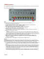
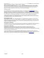
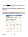
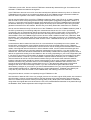
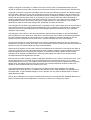
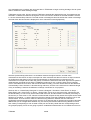
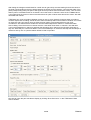
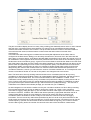
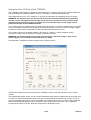
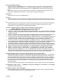
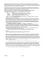
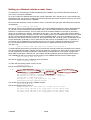
Select a “Module IP-Addr:” of “192.168.1.60” and click the “Connect” button to connect the GUI to the
TTM8000 device.
Now choose a “Measurement Mode” of “I-Mode (8 Chn. cont. / 82.3ps / 64 bit / compressed)” and a “Byte
Order” of “Little Endian (e.g. Intel x86/Alpha)”.
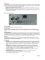
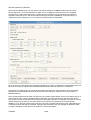
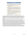
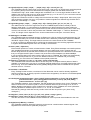
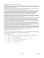
The Signal Input Level determines the threshold voltage that distinguishes low-/high-signal levels. Since the
signal from our signal generator is set to operate using signal levels of 0V and 3V a threshold of 1.5V
provides a nice distinction between low and high. Since 1.5V is a common threshold for TTM signals, we can
easily select then “TTL (+1.5V)” entry from the menu. If we had wanted a non-standard threshold, we could
have chosen “Custom” and entered our own voltage manually. Note that the threshold voltage selected this
way applies to all channels (which is fine for us, since we only have one signal). If we had several signals
that use different threshold voltages, we could chosen “Advanced” from the drop-box and then clicked on the
“Advanced Config.” button to open a dialog that lets us enter a different threshold voltage for each channel
(providing finer control at the price of more mouse-clicks).
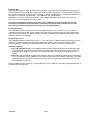
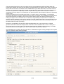
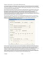
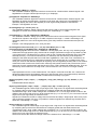
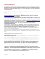
We want to measure timing jitter between two rising edges of a signal. Thus we shall enable rising edges
and disable falling edges. Strictly speaking it would be sufficient to enable the rising edge of the one signal
that we are interested in, however it does not hurt to enable the others too. Note that the checkboxes for
Start are disabled, since “I-Mode cont.” does not use the external Start input.
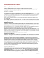
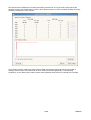
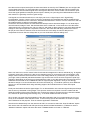
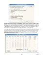
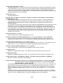
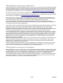
We want to use the application TTMViewer to display the timetags that we will measure. Thus the timetags
shall be sent directly to a port (on our local PC, or any other PC in the local subnet of the TTM8000 board)
via UDP. We can also select “Receiver Req.” to avoid specifying the data target at this time. If we select
“Receiver Request” an application that wishes to receive the data, will request that the data be sent to its
port. Both approaches have their advantages: If you specify a port here, the receiver never needs to detect
the TTM8000 board and can fully concentrate on data processing. However if the receiver specifies itself as
target, the network connection between TTM8000 and receiver application is initiated by the receiver, and
should cause less trouble if a network firewall is active on the PC. Furthermore the selection of an available
UDP port is left to the operating system, thus avoiding collisions between multiple receiver applications
wishing to receive data from different TTM8000s (If we specify data targets explicitly collisions must be
avoided by careful manual assignment of UDP ports.)
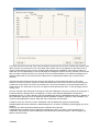
If we wanted to record the timetags for later processing, we could also have them sent to TTMCntrl and have
them written to a file. Note that TTMCntrl will never overwrite an existing file. If it finds the filename already
used, it will append a counter to the filename (MyTimetags.dat becomes MyTimetags[2].dat, or if that is
already used too MyTimetags[3].dat up to MyTimetags[100].dat). In addition to this TTMCntrl supports
macros in filenames and will substitute %TIME%, %DATE% and %COUNT% with appropriate contents. Note
that macro names are case sensitive.
We have now successfully set up the data generation side of our sample application and can move on to the
data processing/evaluation side.
15/60
TTM8000