1
Document type:
User's Manual (MUT)
Title:
Mod. V785, 16/32 Channel Peak Sensing Converter
Revision date:
27/11/2001
Revision:
3
2.3. Zero suppression
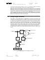
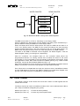
The output of the ADC is fed to a threshold comparator to perform the zero suppression.
If the converted value from a channel is greater than (or equal to) the relevant low
threshold value set via VME in the Thresholds memory (Base Address + 0x1080 ÷
0x10BF, see § 4.39), the result is fed to the dual port memory and will be available for
the readout.
If the converted value is lower than the threshold, the value is stored in the memory only
if the LOW TRESHOLD PROG. bit of the Bit Set 2 Register is set to 1 (see § 4.26). The
fact that the converted value was under the threshold is also flagged in the datum stored
in the memory, where the bit 13 (UNDERTHRESHOLD) of the 16-bit data word is set to
1. The Thresholds memory allows to set a low threshold value for each channel. Default
setting corresponds to thresholds not defined. By setting the bit 8 in the Bit Set 2
Register it is possible to program the Threshold values in 16 ADC counts steps over the
entire full scale range or in 2 ADC counts steps over 1/8 of full scale range∗ . In more
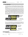
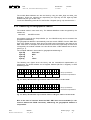
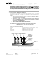
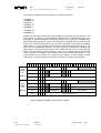
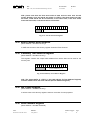
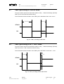
detail, if Bit 8 = 0 (default value) the comparison is performed between the 8 MSB of
each 12 bit converted value and the 8 bit threshold value which is stored in the relevant
register as illustrated in Fig. 2.5. The threshold values can be programmed over the
entire full scale range.
15 14 13 12 11 10 9 8 7 6 5 4 3 2 1 0
ADC CONVERTED VALUE
ADC converted
value from the
channel #n
15 14 13 12 11 10 9 8 7 6 5 4 3 2 1 0
K
THRESHOLD VALUE
Threshold value
for the channel #n
Fig. 2.4: Zero suppression (Bit 8 of Bit Set 2 Register = 0, default setting)
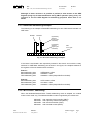
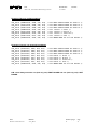
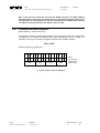
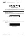
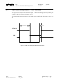
if Bit 8 = 1 (in the Bit Set 2 Register) the comparison is performed between the bit 1…8
of each 12 bit converted value and the 8 bit threshold value which is stored in the
relevant register as illustrated in the figure below (converted value is under threshold if
the value written in the 1…8 bits is smaller than the threshold value and 9…11 bits are
0). The threshold values can be programmed over 1/8 of full scale range.
15 14 13 12 11 10 9 8 7 6 5 4 3 2 1 0
ADC CONVERTED VALUE
15 14 13 12 11 10 9 8 7 6 5 4 3 2 1 0
K
THRESHOLD VALUE
ADC converted
value from the
channel #n
Threshold value
for the channel #n
Fig. 2.5: Zero suppression (Bit 8 of Bit Set 2 Register =1)
∗
This feature is available from firmware releases 5.1; for earlier firmware releases the
thresholds can be programmed only in 16 ADC counts steps (as illustrated in Fig. 2.4).
NPO:
00102/97:V785x.MUTx/03
Filename:
V785_REV3
Number of pages:
74
Page:
14