1
Applicable model: AMR03Y/E
2. Installation assemblies prepared on the site
Serial
CONTENT
PAGE
I.Installation part
Packing list and precautions.............................................1
Notes to installation...........................................................1
Installation procedure........................................................2
Wiring procedure...............................................................2
Safety precautions............................................................2
System wiring instruction..................................................2
II. Operation part
Basic conditions of operating the electric controller..........2
Function categories of electric controller..........................2
Functions of components..................................................2
System composition.......................................................3
Keywords and general function description...................3
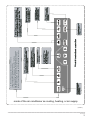
Schematic diagram of centralized controller keys..........3
Electric control function description
(keypad operation instruction)........................................3
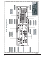
General display data entries........................................4
LCD display description...............................................5
Fault and protection code table....................................5
Technical indices and requirements...............................6
Chart.1............................................................................8
Chart.2............................................................................9
Chart.3..........................................................................10
Chart.4..........................................................................11
Chart5 (LCD full display diagram)................................12
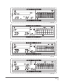
Chart.6,7,8,9.................................................................13
Thank you for your confidence in YORK
.
YORK 2nd-Generation Centralized Controller
This specification manual describes the conditions of
operating the centralized controller and its control functions.
This specification manual is applicable to centralized
controllers. But the functions available from the centralized
controller described herein or the displayed data need support
of the main control board of the air conditioner.
For convenience of future reference, keep this manual
properly after reading it.
For any question, contact the distributor.
I.
Installation part
Name
(Install
No.
1
Quantity
Remarks
wall)
3-core control
2 PCS
shielded cable
RVVP300/300
3x0.75mm 2
One for
communicating
with network
interface module;
the other for
communicating
with the computer.
2
3-core cable
1 PCS
RVV-300/500 For power supply
3x1.5mm 2
of monitor
3
Switch box
1 PCS
--------
--------
4
Wire pipe (jack 2 3 PCS
/
--------
--------
--------
For binding cables(as
casing pipe,
captive nut)
5
Tighten strip
Several
pieces
the case may be)
Notes to installation
Notes to installation of centralized controller:
1. Power supply of the centralized controller. Connect the
220V~50Hz power supply to the L and N sides of the terminal on
the back of the centralized controller.
2. Do not place the signal cable and power cable of the centralized controller into the same wire pipe. An interval of
300~500mm should exist between the two pipes.
3. The main signal cable of the centralized controller shall
not exceed 1200m.
4. No intermediate joint is allowed for the shielded cable. If joints
are inevitable, crimp it with the terminal.
5. After the centralized controller is connected, do not use
megohmmeter to inspect insulation of the signal cable.
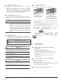
6. Wiring mode of the centralized controller and the network
interface:
The communication port between the centralized controller and
the network interface of the air conditioner is polarity-sensitive. The
X, Y and E at both sides should correspond properly. Dot not
cross-connect cables. The same principles apply to the RS485RS232 of the centralized controller.
Correct connection
List of fittings and precautions
Selected
into model
Correct connection
1. Packing box list of 2nd-generation indoor unit centralized
controller AMR03Y. Check whether the assemblies are
complete.
Serial
Name
Quantity
Remarks
2nd-generation indoor
1 PCS
AMR03Y/E
No.
1
Incorrect connection
Incorrect connection
unit centralized
controller
2
Fastening cross
6 PCS
groove pan head
GB845/ST3.8X25-C-H
(S)
self-tapping screw
3
Fastening plastic
6 PCS
6X30
1 PCS
YDS06IU-012a
2 PCS
120 ohms<
expansion pipe
4
Installation &
Operation Manual
5
Matching resistance
I&O manual
1