1
Printed in Hong Kong
PA: OI-AL/EN-1301-V4.0
Features
ARM + Auror CPU
Embedded breathing lamp
Support 50 wireless sensors and 10 remote controls
Built-in 1,000,000 RF codes combination
maintains high reliability
Cellular communicator, simple operation
Store 5 alarm phone numbers
Exit & entry delay
SMS alert for low battery of two-way accessories
Arm & disarm the system by SMS or free phone call
Remote monitoring site via phone
Built-in 110dB siren, deterring intruders on site
Built-in 4 pcs of AA 1.5V/1800mAh rechargeable
battery enables 12-hour standby
SMS alerts for power failure,
power recovery and low power
850/900/1800/1900MHz GSM frequency,
applicable for universal
1
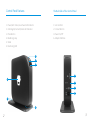
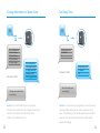
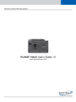
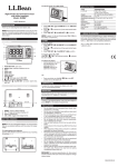
Control Panel Features
The Back Side of the Control Panel
1. Power/Arm Status/Low Power LED Indicator
1. Sim Card Slot
2. GSM Signal/Connect/Alarm LED Indicator
2. Connect Button
3. Panic Button
3. Power On/Off
4. Breathing Lamp
4. Adapter Interface
5. Stand
6. Monitoring MIC
1
2
3
1
4
2
3
4
5
6
2
3
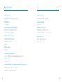
LED Indication
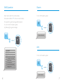
Connect Wireless Siren
1
1. Power/Arm Status/
The newly-added wireless siren can be used after
Low Power LED Indicator
connecting to the control panel.
Disarm in green.
Arm in yellow.
2
Lower power flashes in green.
Operation:
Press the Connect Button of the wireless siren for 0.5
second, the Connect Button LED indicator lights on,
2. GSM Signal/Connect/
Alarm LED Indicator
and then press the SOS Button on the control panel,
GSM network searching: Fast flashes in green.
the siren will be connected after one beep is heard.
GSM signal is normal: Slow flashes in green.
Connect LED: Lights in red.
Alarm LED: Fast flashes in red.
Connect Accessories
Press connect button
, the connect LED lights on, then
Testing: Press the Arm Button on the remote control,
to make sure that the internal siren and wireless siren
both beep once, the connection is successful. If not,
the connection fails, please reconnect them.
Once the intruder is detected, both internal siren
trigger the accessory once, it will be connected after a beep.
and wireless siren will hoot to deter the illegal intruder.
Once two beeps are heard, the accessory has been connected before.
At the same time, the alarm system will send SMS and
(The siren will be off in 5 minutes as the default setting).
The first connected accessory is in Zone 1, the second one in
auto dial to users.
Zone 2, and so on.
4
5
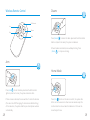
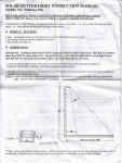
SMS Operation
Disarm
Insert a sim card to the control panel,
To turn off the alarm system
then send an SMS of “?” to the sim card number,
the operation guide message will be replied.
You can control the alarm system
0
by following the guide message:
?
System disarmed.
Arm
‘0’
‘1’
‘2’
‘3’
‘4’
Disarm
Arm
Call-back monitor
Store phone numbers
Change information of
alarm zones
‘5’ Set delay time
‘6’ Set siren volume and
ringing time
To turn on the alarm system
1
System armed.
6
7
Call-back Monitor
2
Send “2” to the sim card number,
the alarm will call back. Pick up the phone
and start to monitor the site.
Store Phone Numbers
3
TEL:
1.
2.
3.
4.
5.
Forward > Edit
TEL:
1. 67890033
2. 67890022
3. 67890011
4. 67890000
5.
Store phone numbers
successfully.
8
9
Change Information of Alarm Zone
Set Delay Time
4
5
Zone information:
1. Zone 1 alarm
2. Zone 2 alarm
3. Zone 3 alarm
4. Zone 4 alarm
Alarm delay time
(0-300sec):
0
Forward > Edit
Zone information:
1. Home gate alarm
2. Living room PIR
3. Bedroom PIR
4. Garage gate alarm
Change zone information
successfully.
Forward > Edit
Alarm delay time
(0-300sec):
10
Set alarm delay time
successfully.
Notice! Due to SMS character limit, only 4 zones
Notice! Once the function is setup, when you arm the system,
contents can be edited. At most 30 English characters for
one beep will be heard every second to remind the user to
each line. Other alarm zones are fixed as Zone
leave. The reminding rhythm will be speeded up in the last 15
5 alarm, Zone 6 alarm and so on.
seconds. Once the intruder is detected, the alarm will be
delayed accordingly.
10
11
Set Siren Volume and Ringing Time
SMS Alert for Low Battery of Accessories
(available for two-way accessories such as DWC-102 and PIR-900/910)
SMS will be sent for 1-4 zones with its zone name as
“Zone name + low battery”.
6
Bedroom PIR low battery.
SMS alert for 5~50 zones will be “Zone number + low battery”.
Siren volume (0 Mute, 1 Low,
2 Medium, 3 High) :
2
Siren ringing time (1-9min) :
5
Zone 10 low battery.
SMS Alert for Tamper Alarm of Accessories
(available for two-way accessories such as DWC-102 and PIR-900/910)
Forward > Edit
Siren volume (0 Mute, 1 Low,
2 Medium, 3 High) :
3
Siren ringing time (1-9min) :
3
SMS will be sent for 1-4 zones with its zone name as
“Zone name + tamper alarm”.
Bedroom PIR tamper
alarm.
SMS alert for 5~50 zones will be “Zone number + tamper alarm”.
Set siren volume and
ringing time successfully.
Zone 10 tamper alarm.
12
13
Arm & Disarm by Free Phone Call
Arm
Call the control panel number, hang up when hearing
the ring tone. The panel will call back. The user hangs
Clear Accessories
Press down the connect button
until 2 beeps are
heard. All the connected accessories will be cleared.
up the phone directly to arm the system.
Language Setup
Disarm
Call the control panel number, hold on until
the panel hangs up the call.
The SMS language can be modified by sending SMS code
The panel will not call back. System is disarmed.
to the SIM card of the alarm system.
Emergency Call
0086
Chinese
0001
English
Press “SOS” button on the control panel or the
remote control, the system will alarm immediately
and send SMS of “Emergency Call”.
Turn On/Off the Breathing LED
Restore Factory Setting
Send text 30 to SIM card number of control panel to turn off
14
the breathing LED. (Notice! No SMS reply from control panel.)
Press connect button and SOS button on the
Send text 31 to SIM card number of control panel to turn on
control panel at the same time, after three beeps,
the breathing LED. (Notice! No SMS reply from control panel.)
all settings are restored to default.
15
Specifications
Product name :
Radio frequency
GSM/SMS Security Alarm System
315MHz/433MHz (±75KHz)
Model No. :
Housing material
CG-8800G3
ABS plastic
Control panel’s power supply :
Operation condition:
Input: AC 110-240V/50-60Hz
Temperature: -10ºC~55 ºC
Output: DC 12V/500mA
Humidity: ≤ 80%(non-condensing)
GSM working frequency :
Size (L x W x H) :
850/900/1800/1900MHz
Panel : 12.6×3.6×13cm
Standby current :
Stand : 15×7×1cm
80mA
Alarm current :
170mA
Internal battery backup :
AA 1.5V/1800mAh rechargeable battery x 4 pcs
Internal siren :
110dB
Allowed amount of expandable wireless accessories
10 PCS Wireless Remote Control
and 50 PCS Wireless Sensors
16
17
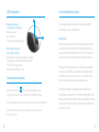
Wireless Remote Control
Disarm
LED Indicator
Arm
Stay
Disarm
Panic
Press {Disarm
} to disarm the alarm panel and the LED indicator
blacks out (siren hoots twice), the system is disarmed.
When intruders are detected, siren will keep hooting. Press
{Disarm
} to stop siren hooting.
Arm
Home Mode
Press {Arm
} to arm the alarm panel and the LED indicator
lights on (siren hoots once), the system enters Arm state.
If there comes an intruder, the siren will hoot to deter the intruder.
18
Press {Stay
} button on the remote control, the system state
(The siren turns off after ringing for 5 minutes as default setting.)
LED is on. All the sensors in other zones are armed except the
At the same time, the system dials the pre-stored phone numbers
motion detector in zone A which is disarmed so that user can
automatically.
move freely at home.
19
Mute Mode
Home Mode Zone Setup
Home Mode Zone
Press {Stay
{Arm
Normal Zone
} button on the remote control, then press
} or {Disarm
} button, the siren keeps silent to finish
the operation. The system is armed or disarmed in mute without
disturbing other people.
The PIR motion detector is set in Home Mode Zone in default.
Users should reconnect the detector with the control panel after
the zone is changed.
Emergency Call
24-H Zone
No matter what state the control panel is in, once SOS button on
Note: It is recommended to set smoke detector, gas
detector and outdoor beam sensor at 24-H zone.
the remote control is pressed, the system immediately goes into
emergent alarming state.
20
21
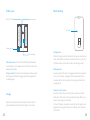
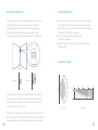
Wireless Door/Window Contact
LED Indication
Features
LED flashes once: Door/window is opened and
transmitter sends signal to the control panel.
LED flashes quickly: Low power indication, please
change battery as soon as possible.
The DWC- 100 is a Door/Window Contact that can be
installed on doors, windows, and any other objects that open
and close. The sensor transmits signals to the control panel
when a mag net mou nted near the sensor is mov ed away.
External input for wired accessor y is available at the N/C
interface. The tampe r protection ensures that sabotage
attempt s to mov e the contact will result in an alarm activation.
PCB Layout
Appearance
LED indicator
Magnet
Tamper switch
AA 1.5V LR6
Transmitter
Zone setting
22
23
Installation & Notice
Ope n the case and remov e the battery activation strip.
Mou nt the sensor on the door frame and the mag net on the door.
Mak e sure the mag net is on the right side of the transmitter
Place the transmitter in the desired location, mou nt the
mag net no more than 1cm away from the transmitter and secure
the transmitter and mag net with double-sided tapes or screws.
Avoid mou nting sensors in areas with a large quantity of met al
or electrical wiring, such as a furnace or utility room.
Specifications
Powe r supply
DC 1.5V (AA 1.5V LR6 Battery x 1pc)
Static current
≤ 30uA
Alarm current
≤ 40mA
Transmitting distance
≤80m (in open area)
Radio frequency
315MHz /433MHz (±75KHz)
Housing mat erial
ABS plastic
Ope rating tempe rature
-10°C~55°C
Relative humidity
≤80% (non-condensing)
Transmitter dimen sions (LxWxH)
71 x 34 x 17.5mm
Mag net dimen sions (LxWxH)
51 x 12 x 13.5mm
24
25
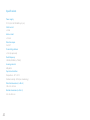
Wireless PIR Motion Detector
Appearance
1. Detection window
2. LED indicator
3. Bracket
Features
PIR-900 is a high performan ce wireless P.I.R. mot ion detector.
It consists of digital dual-core fuzzy logic infrared control
chip and intelligent analysis which effectively identify
interference signals from body mov emen t signals and reduce
false alarm rate. With automa tic tempe rature comp ensation
and anti-air turbulence technology, it easily adapts to
environme ntal changes. The detector also has the advantages
of energy saving, reliability and easy installation.
1
2
3
LED Indication
Flash continuously: Under the self-testing state.
Flash once: Intruder is detected.
Flash twice: Self-testing is finished, enters the working mod e.
Flash once per 3 seconds: Under voltage indication, please
change the batteries immed iately.(User will get alert SMS
about the low battery if the PIR detector is connected to the
GSM alarm system.)
26
27
PCB Layout
Mode Setting
LED ON / OFF
Infrared sensor
AA 1.5V LR6
AA 1.5V LR6
Test Button
Tamper switch
Zone setting
Infrared sensor: It detects the infrared rays released by
human body motion, please don’t touch the surface and
always keep it clean.
Tamper switch: Once the case is opened in working state,
the tamper switch will be triggered and then generates
an alarm signal.
Usage
Ope n the case and remov e the battery activation strip to
activate batteries. It will start self-testing for one minute.
28
Testing mod e:
Af ter self-testing, press the test button, the sensor enters testing
mod e, and detects once every 10 seconds. Af ter 3 minutes, the
LED flashes twice, and the sensor enters the working mod e.
Working mod e:
In working state, if the sensor is triggered more than twice within
3 minutes, it will enter sleeping mod e to save power. Af ter no
mov emen t within next 3 minutes, the sensor goes back to the
working mod e.
Connect to alarm pan el:
Press the connect key on the alarm panel, and then press the
test button of the sensor twice to send alarm signal. Whe n one
beep is heard, they are connected.
To check if they are connected successfully, arm the system, and
trigger the sensor again, if there is an alarming, the connection
is successful.
29
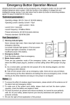
Installation & Notices
Testing (Walk Test)
Avoid mou nting the detector close to windows, air conditioner,
heater, refrigerator, oven, su nshine and places where the
tempe rature changes fast or the air stream flows frequently.
If two detectors are installed in the same detection scope,
please adjust the location to avoid interference and false alarm.
A. Af ter installation, power on the detector. Af ter one minute
self-testing, press the test button, walk in the scope (from
left to right or from right to left) and watch the LED indicator
to mak e sure the detector is working.
B. The LED indicator flashes once when body
mov emen t is detected.
C. Adjust the detector angle accordingly to achieve the best
detection effect.
2m
Detection Scope
Ground
Top view
Side view
0m
110°
Fix the bracket on the wall with screws and attach the detector to
the bracket. Adjust installation height or bracket to change the
detection distance and angle. It is recomme nded to mou nt it at
the height of 2m from the ground.
2m
4m
6m
8m
2m
0m
Top view
Side view
The detector is more sensitive to the cross mov emen t than to the
vertical mov emen t, so the performance of detector is best when the
detection direction is vertical to the walking direction of people.
30
31
Specifications
Powe r supply
DC 3V (AA 1.5V LR6 Battery x 2 pcs)
Static current
≤ 50uA
Alarm current
≤ 9.5mA
Detection scope
8m/110°
Transmitting distance
≤ 80m (in open area)
Radio frequency
315MHz /433MHz (± 75KHz)
Housing mat erial
ABS plastic
Ope ration Condition
Tempe rature: -10°C~55°C
Relative humi dity: ≤80% (non-condensing)
Detector dimen sions (L x W x H)
108 x 52 x 36.8 mm
Bracket dimen sions (L x W x H)
52 x 30 x 26.5 mm
32