1
Freescale Semiconductor, Inc.
Freescale Semiconductor, Inc...
SECTION 8
EXCEPTION PROCESSING
Exception processing is defined as the activities performed by the processor in preparing to
execute a handler routine for any condition that causes an exception. In particular, exception
processing does not include execution of the handler routine itself. An introduction to
exception processing, as one of the processing states of the MC68030 processor, was given
in Section 4 Processing States. This section describes exception processing in detail,
describing the processing for each type of exception. It describes the return from an
exception and bus fault recovery. This section also describes the formats of the exception
stack frames. For details of MMU-related exceptions, refer to Section 9 Memory
Management Unit. For more detail on protocol violation and coprocessor-related
exceptions, refer to Section 10 Coprocessor Interface Description. Also, for more detail
on exceptions defined for floating-point coprocessors, refer to the user's manual for the
MC68881/MC68882.
8.1 EXCEPTION PROCESSING SEQUENCE
Exception processing occurs in four functional steps. However, all individual bus cycles
associated with exception processing (vector acquisition, stacking, etc.) are not guaranteed
to occur in the order in which they are described in this section. Nonetheless, all addresses
and offsets from the stack pointer are guaranteed to be as described.
The first step of exception processing involves the status register. The processor makes an
internal copy of the status register. Then the processor sets the S bit, changing to the
supervisor privilege level. Next, the processor inhibits tracing of the exception handler by
clearing the T1 and T0 bits. For the reset and interrupt exceptions, the processor also
updates the interrupt priority mask.
In the second step, the processor determines the vector number of the exception. For
interrupts, the processor performs an interrupt acknowledge cycle (a read from the CPU
address space type $F; see Figures 7-45 and 7-46) to obtain the vector number. For
coprocessor-detected exceptions, the vector number is included in the coprocessor
exception primitive response.
MOTOROLA
MC68030 USER’S MANUAL
For More Information On This Product,
Go to: www.freescale.com
8-1
Freescale Semiconductor, Inc.
Exception Processing
(Refer to Section 10 Coprocessor Interface Description for a complete discussion of
coprocessor exceptions.) For all other exceptions, internal logic provides the vector number.
This vector number is used in the last step to calculate the address of the exception vector.
Throughout this section, 9 vector numbers are given in decimal notation.
Freescale Semiconductor, Inc...
For all exceptions other than reset, the third step is to save the current processor context.
The processor creates an exception stack frame on the active supervisor stack and fills it
with context information appropriate for the type of exception. Other information may also
be stacked, depending on which exception is being processed and the state of the processor
prior to the exception. If the exception is an interrupt and the M bit of the status register is
set, the processor clears the M bit in the status register and builds a second stack frame on
the interrupt stack.
The last step initiates execution of the exception handler. The processor multiplies the
vector number by four to determine the exception vector offset. It adds the offset to the value
stored in the vector base register to obtain the memory address of the exception vector.
Next, the processor loads the program counter (and the interrupt stack pointer (ISP) for the
reset exception) from the exception vector table in memory. After prefetching the first three
words to fill the instruction pipe, the processor resumes normal processing at the address in
the program counter. Table 8-1 contains a description of all the exception vector offsets
defined for the MC68030.
Table 8-1. Exception Vector Assignments (Sheet 1 of 2)
Vector
Number(s)
8-2
Vector Offset
Assignment
STATUS
Asserted
Hex
Space
0
1
2
3
000
004
008
00C
SP
SP
SD
SD
Reset Initial Interrupt Stack Pointer
Reset Initial Program Counter
Bus Error
Address Error
—
—
YES
YES
4
5
6
7
010
014
018
01C
SD
SD
SD
SD
Illegal Instruction
Zero Divide
CHK, CHK2 Instruction
cpTRAPcc, TRAPcc, TRAPV Instructions
NO
NO
NO
NO
8
9
10
11
020
024
028
02C
SD
SD
SD
SD
Privilege Violation
Trace
Line 1010 Emulator
Line 1111 Emulator
NO
YES
NO
YES
12
13
14
15
030
034
038
03C
SD
SD
SD
SD
(Unassigned, Reserved)
Coprocessor Protocol Violation
Format Error
Uninitialized Interrupt
—
NO
NO
YES
MC68030 USER’S MANUAL
For More Information On This Product,
Go to: www.freescale.com
MOTOROLA
Freescale Semiconductor, Inc.
Exception Processing
Table 8-1. Exception Vector Assignments (Sheet 2 of 2)
Freescale Semiconductor, Inc...
Vector
Number(s)
16
Through
23
24
25
26
27
28
29
30
31
32
Through
47
48
49
50
51
52
53
54
55
56
57
58
59
Through
63
64
Through
255
Vector Offset
Hex
040
Space
SD
05C
060
064
068
06C
070
074
078
07C
080
SD
SD
SD
SD
SD
SD
SD
SD
SD
SD
0BC
0C0
0C4
0C8
0CC
0D0
0D4
0D8
0DC
0E0
0E4
0E8
0EC
SD
SD
SD
SD
SD
SD
SD
SD
SD
SD
SD
SD
SD
0FC
100
SD
SD
3FC
SD
Assignment
Unassigned, Reserved
STATUS
Asserted
—
Spurious Interrupt
Level 1 Interrupt Autovector
Level 2 Interrupt Autovector
Level 3 Interrupt Autovector
Level 4 Interrupt Autovector
Level 5 Interrupt Autovector
Level 6 Interrupt Autovector
Level 7 Interrupt Autovector
Yes
Yes
Yes
Yes
Yes
Yes
Yes
Yes
TRAP #0-15 Instruction Vectors
No
FPCP Branch or Set on Unordered Condition
FPCP Inexact Result
FPCP Divide by Zero
FPCP Underflow
FPCP Operand Error
FPCP Overflow
FPCP Signaling NAN
Unassigned, Reserved
MMU Configuration Error
Defined for MC68851 not used by MC68030
Defined for MC68851 not used by MC68030
No
No
No
No
No
No
No
No
No
—
—
Unassigned, Reserved
—
User Defined Vectors (192)
Yes
SP = Supervisor Program Space
SD = Supervisor Data Space
As shown in Table 8-1, the first 64 vectors are defined by Motorola and 192 vectors are
reserved for interrupt vectors defined by the user. However, external devices may use
vectors reserved for internal purposes at the discretion of the system designer.
MOTOROLA
MC68030 USER’S MANUAL
For More Information On This Product,
Go to: www.freescale.com
8-3
Freescale Semiconductor, Inc.
Exception Processing
The MC68030 provides the STATUS signal to identify instruction boundaries and some
exceptions. As shown in Table 8-2, STATUS indicates an instruction boundary and
exceptions to be processed, depending on the state of the internal microsequencer. In
addition, STATUS indicates when an MMU address translation cache miss has occurred
and the processor is about to begin a table search access for the logical address that caused
the miss. Instruction-related exceptions do not cause the assertion of STATUS as shown in
Table 8-1. For STATUS signal timing information, refer to Section 12 Applications
Information.
Table 8-2. Microsequencer STATUS Indications
Freescale Semiconductor, Inc...
Asserted for
1 Clock
2 Clocks
3 Clocks
Continuously
8-4
Indicates
Sequencer at instruction boundary will begin execution of next instruction.
Sequencer at instruction boundary but will not begin the next instruction
immediately due to:
• pending trace exception
OR
• pending interrupt exception
MMU address translation cache miss — processor to begin table serach
OR
Exception processing to begin for:
• reset OR
• bus error OR
• address error OR
• spurious interrupt OR
• autovectored interrupt OR
• F-line instruction (no coprocessor responded)
Processor halted due to double bus fault.
MC68030 USER’S MANUAL
For More Information On This Product,
Go to: www.freescale.com
MOTOROLA
Freescale Semiconductor, Inc.
Exception Processing
8.1.1 Reset Exception
Assertion by external hardware of the RESET signal causes a reset exception. For details
on the requirements for the assertion of RESET, refer to 7.8 Reset Operation.
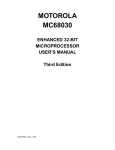
The reset exception has the highest priority of any exception; it provides for system
initialization and recovery from catastrophic failure. When reset is recognized, it aborts any
processing in progress, and that processing cannot be recovered. Figure 8-1 is a flowchart
of the reset exception, which performs the following operations:
1. Clears both trace bits in the status register to disable tracing.
Freescale Semiconductor, Inc...
2. Places the processor in the interrupt mode of the supervisor privilege level by setting
the supervisor bit and clearing the master bit in the status register.
3. Sets the processor interrupt priority mask to the highest priority level (level 7).
4. Initializes the vector base register to zero ($00000000).
5. Clears the enable, freeze, and burst enable bits for both on-chip caches and the writeallocate bit for the data cache in the cache control register.
6. Invalidates all entries in the instruction and data caches.
7. Clears the enable bit in the translation control register and the enable bits in both transparent translation registers of the MMU.
8. Generates a vector number to reference the reset exception vector (two long words)
at offset zero in the supervisor program address space.
9. Loads the first long word of the reset exception vector into the interrupt stack pointer.
10. Loads the second long word of the reset exception vector into the program counter.
After the initial instruction prefetches, program execution begins at the address in the
program counter. The reset exception does not flush the address translation cache (ATC),
nor does it save the value of either the program counter or the status register.
MOTOROLA
MC68030 USER’S MANUAL
For More Information On This Product,
Go to: www.freescale.com
8-5
Exception Processing
Freescale Semiconductor, Inc.
.
ENTRY
➧
➧
➧
➧
➧
➧
S
1
M
0
T0, T1
0
I2-I0
$7
$0
VBR
CACR
$0
INSTRUCTION AND
DATA CACHE
ENTRIES INVALIDATED
Freescale Semiconductor, Inc...
FETCH VECTOR #0
OTHERWISE
SP (VECTOR #0)
BUS ERROR
➧
(DOUBLE BUS FAULT)
ASSERT STATUS
CONTINUOUSLY
FETCH VECTOR #1
EXIT
OTHERWISE
PC (VECTOR #1)
BUS ERROR
➧
(DOUBLE BUS FAULT)
PREFETCH 3 WORDS
ASSERT STATUS
CONTINUOUSLY
EXIT
OTHERWISE
BEGIN INSTRUCTION
EXECUTION
BUS ERROR OR ADDRESS ERROR
(DOUBLE BUS FAULT)
EXIT
ASSERT STATUS
CONTINUOUSLY
EXIT
Figure 8-1. Reset Operation Flowchart
8-6
MC68030 USER’S MANUAL
For More Information On This Product,
Go to: www.freescale.com
MOTOROLA
Freescale Semiconductor, Inc.
Exception Processing
As described in 7.5.4 Double Bus Fault, if bus error or address error occur during the
exception processing sequence for a reset, a double bus fault occurs. The processor halts,
and the STATUS signal is asserted continuously to indicate the halted condition.
Execution of the reset instruction does not cause a reset exception, nor does it affect any
internal registers, but it does cause the MC68030 to assert the RESET signal, resetting all
external devices.
Freescale Semiconductor, Inc...
8.1.2 Bus Error Exception
A bus error exception occurs when external logic aborts a bus cycle by asserting the BERR
input signal. If the aborted bus cycle is a data access, the processor immediately begins
exception processing. If the aborted bus cycle is an instruction prefetch, the processor may
delay taking the exception until it attempts to use the prefetched information. The assertion
of the BERR signal during the second, third, or fourth access of a burst operation does not
cause a bus error exception, but the burst is aborted. Refer to 6.1.3.2 Burst Mode Filling
and 7.5.1 Bus Errors for details on the effects of bus errors during burst operation.
A bus error exception also occurs when the MMU detects that a successful address
translation is not possible. Furthermore, when an ATC miss occurs and an external bus
cycle is required, the MMU must abort the bus cycle, search the translation tables in memory
for the mapping, and then retry the bus cycle. If a valid translation for the logical address is
not available due to a problem encountered during the table search (the attempt to access
the appropriate page descriptor in the translation tables for that page), a bus error exception
occurs when the aborted bus cycle is retried.
The problem encountered could be a limit violation, an invalid descriptor, or the assertion of
the BERR signal during a bus cycle used to access the translation tables. A miss in the ATC
causes the processor to automatically initiate a table search but does not cause a bus error
exception unless one of the specific conditions mentioned above is encountered.
MOTOROLA
MC68030 USER’S MANUAL
For More Information On This Product,
Go to: www.freescale.com
8-7
Exception Processing
Freescale Semiconductor, Inc.
Freescale Semiconductor, Inc...
The processor begins exception processing for a bus error by making an internal copy of the
current status register. The processor then enters the supervisor privilege level (by setting
the S bit in the status register) and clears the trace bits. The processor generates exception
vector number 2 for the bus error vector. It saves the vector offset, program counter, and the
internal copy of the status register on the stack. The saved program counter value is the
logical address of the instruction that was executing at the time the fault was detected. This
is not necessarily the instruction that initiated the bus cycle, since the processor overlaps
execution of instructions. The processor also saves the contents of some of its internal
registers. The information saved on the stack is sufficient to identify the cause of the bus
fault and recover from the error.
For efficiency, the MC68030 uses two different bus error stack frame formats. When the bus
error exception is taken at an instruction boundary, less information is required to recover
from the error, and the processor builds the short bus fault stack frame as shown in Table
8-7. When the exception is taken during the execution of an instruction, the processor must
save its entire state for recovery and uses the long bus fault stack frame shown in Table 87. The format code in the stack frame distinguishes the two stack frame formats. Stack
frame formats are described in detail in 8.4 Exception Stack Frame Formats.
If a bus error occurs during the exception processing for a bus error, address error, or reset
or while the processor is loading internal state information from the stack during the
execution of an RTE instruction, a double bus fault occurs, and the processor enters the
halted state as indicated by the continuous assertion of the STATUS signal. In this case, the
processor does not attempt to alter the current state of memory. Only an external RESET
can restart a processor halted by a double bus fault.
8.1.3 Address Error Exception
An address error exception occurs when the processor attempts to prefetch an instruction
from an odd address. This exception is similar to a bus error exception, but is internally
initiated. A bus cycle is not executed, and the processor begins exception processing
immediately. After exception processing commences, the sequence is the same as that for
bus error exceptions described in the preceding paragraphs, except that the vector number
is 3 and the vector offset in the stack frame refers to the address error vector. Either a short
or long bus fault stack frame may be generated. If an address error occurs during the
exception processing for a bus error, address error, or reset, a double bus fault occurs.
8-8
MC68030 USER’S MANUAL
For More Information On This Product,
Go to: www.freescale.com
MOTOROLA
Freescale Semiconductor, Inc.
Exception Processing
8.1.4 Instruction Trap Exception
Certain instructions are used to explicitly cause trap exceptions. The TRAP #n instruction
always forces an exception and is useful for implementing system calls in user programs.
The TRAPcc, TRAPV, cpTRAPcc, CHK, and CHK2 instructions force exceptions if the user
program detects an error, which may be an arithmetic overflow or a subscript value that is
out of bounds.
Freescale Semiconductor, Inc...
The DIVS and DIVU instructions force exceptions if a division operation is attempted with a
divisor of zero.
When a trap exception occurs, the processor copies the status register internally, enters the
supervisor privilege level, and clears the trace bits. If tracing is enabled for the instruction
that caused the trap, a trace exception is taken after the RTE instruction from the trap
handler is executed, and the trace corresponds to the trap instruction; the trap handler
routine is not traced. The processor generates a vector number according to the instruction
being executed; for the TRAP #n instruction, the vector number is 32 plus n. The stack frame
saves the trap vector offset, the program counter, and the internal copy of the status register
on the supervisor stack. The saved value of the program counter is the logical address of
the instruction following the instruction that caused the trap. For all instruction traps other
than TRAP #n, a pointer to the instruction that caused the trap is also saved. Instruction
execution resumes at the address in the exception vector after the required instruction
prefetches.
8.1.5 Illegal Instruction and Unimplemented Instruction Exceptions
An illegal instruction is an instruction that contains any bit pattern in its first word that does
not correspond to the bit pattern of the first word of a valid MC68030 instruction or is a
MOVEC instruction with an undefined register specification field in the first extension word.
An illegal instruction exception corresponds to vector number 4 and occurs when the
processor attempts to execute an illegal instruction.
MOTOROLA
MC68030 USER’S MANUAL
For More Information On This Product,
Go to: www.freescale.com
8-9
Exception Processing
Freescale Semiconductor, Inc.
An illegal instruction exception is also taken if a breakpoint acknowledge bus cycle (see
7.4.2 Breakpoint Acknowledge Cycle) is terminated with the assertion of the bus error
signal. This implies that the external circuitry did not supply an instruction word to replace
the BKPT instruction word in the instruction pipe.
Freescale Semiconductor, Inc...
Instruction word patterns with bits [15:12] equal to $A are referred to as unimplemented
instructions with A-line opcodes. When the processor attempts to execute an
unimplemented instruction with an A-line opcode, an exception is generated with vector
number 10, permitting efficient emulation of unimplemented instructions.
Instructions that have word patterns with bits [15:12] equal to $F, bits [11:9] equal to $0, and
defined word patterns for subsequent words are legal MMU instructions. Instructions that
have bits [15:12] of the first words equal to $F, bits [11:9] equal to $0, and undefined patterns
in subsequent words are treated as unimplemented instructions with F-line opcodes when
execution is attempted in supervisor mode. When execution of the same instruction is
attempted in user mode, a privilege violation exception is taken. The exception vector
number for an unimplemented instruction with an F-line opcode is number 11.
The word patterns with bits [15:12] equal to $F and bits [11:9] not equal to zero are used for
coprocessor instructions. When the processor identifies a coprocessor instruction, it runs a
bus cycle referencing CPU space type $2 (refer to 4.2 Address Space Types) and
addressing one of seven coprocessors (1-7, according to bits [11:9]). If the addressed
coprocessor is not included in the system and the cycle terminates with the assertion of the
bus error signal, the instruction takes an unimplemented instruction (F-line opcode)
exception. The system can emulate the functions of the coprocessor with an F-line
exception handler. Refer to Section 10 Coprocessor Interface Description for more
details.
8-10
MC68030 USER’S MANUAL
For More Information On This Product,
Go to: www.freescale.com
MOTOROLA
Freescale Semiconductor, Inc.
Exception Processing
Freescale Semiconductor, Inc...
Exception processing for illegal and unimplemented instructions is similar to that for
instruction traps. When the processor has identified an illegal or unimplemented instruction,
it initiates exception processing instead of attempting to execute the instruction. The
processor copies the status register, enters the supervisor privilege level, and clears the
trace bits, disabling further tracing. The processor generates the vector number, either 4,
10, or 11, according to the exception type. The illegal or unimplemented instruction vector
offset, current program counter, and copy of the status register are saved on the supervisor
stack, with the saved value of the program counter being the address of the illegal or
unimplemented instruction. Instruction execution resumes at the address contained in the
exception vector. It is the responsibility of the handling routine to adjust the stacked program
counter if the instruction is emulated in software or is to be skipped on return from the
handler.
8.1.6 Privilege Violation Exception
To provide system security, the following instructions are privileged:
ANDI TO SR
EOR to SR
cpRESTORE
cpSAVE
MOVE from SR
MOVE to SR
MOVE USP
MOVEC
MOVES
ORI to SR
PFLUSH
PLOAD
PMOVE
PTEST
RESET
RTE
STOP
An attempt to execute one of the privileged instructions while at the user privilege level
causes a privilege violation exception. Also, a privilege violation exception occurs if a
coprocessor requests a privilege check and the processor is at the user level.
MOTOROLA
MC68030 USER’S MANUAL
For More Information On This Product,
Go to: www.freescale.com
8-11
Exception Processing
Freescale Semiconductor, Inc.
Exception processing for privilege violations is similar to that for illegal instructions. When
the processor identifies a privilege violation, it begins exception processing before executing
the instruction. The processor copies the status register, enters the supervisor privilege
level, and clears the trace bits. The processor generates vector number 8, the privilege
violation exception vector, and saves the privilege violation vector offset, the current
program counter value, and the internal copy of the status register on the supervisor stack.
The saved value of the program counter is the logical address of the first word of the
instruction that caused the privilege violation. Instruction execution resumes after the
required prefetches from the address in the privilege violation exception vector.
Freescale Semiconductor, Inc...
8.1.7 Trace Exception
To aid in program development, the M68000 processors include instruction-by-instruction
tracing capability. The MC68030 can be programmed to trace all instructions or only
instructions that change program flow. In the trace mode, an instruction generates a trace
exception after it completes execution, allowing a debugger program to monitor execution
of a program.
The T1 and T0 bits in the supervisor portion of the status register control tracing. The state
of these bits when an instruction begins execution determines whether the instruction
generates a trace exception after the instruction completes. Clearing both T bits disables
tracing, and instruction execution proceeds normally. Clearing the T1 bit and setting the T0
bit causes an instruction that forces a change of flow to take a trace exception. Instructions
that increment the program counter normally do not take the trace exception. Instructions
that are traced in this mode include all branches, jumps, instruction traps, returns, and
coprocessor instructions that modify the program counter flow. This mode also includes
status register manipulations, because the processor must re-prefetch instruction words to
fill the pipe again any time an instruction that can modify the status register is executed. The
execution of the BKPT instruction causes a change of flow if the opcode replacing the BKPT
is an instruction that causes a change of flow (i.e., a jump, branch, etc.). Setting the T1 bit
and clearing the T0 bit causes the execution of all instructions to force trace exceptions.
Table 8-3 shows the trace mode selected by each combination of T1 and T0.
8-12
MC68030 USER’S MANUAL
For More Information On This Product,
Go to: www.freescale.com
MOTOROLA
Freescale Semiconductor, Inc.
Exception Processing
Table 8-3. Tracing Control
Freescale Semiconductor, Inc...
T1
0
0
1
1
T0
0
1
0
1
Tracing Function
No Tracing
Trace on Change of Flow (BRA, JMP, etc.)
Trace on Instruction Execution (Any Instruction)
Undefined, Reserved
In general terms, a trace exception is an extension to the function of any traced instruction
— that is, the execution of a traced instruction is not complete until the trace exception
processing is completed. If an instruction does not complete due to a bus error or address
error exception, trace exception processing is deferred until after the execution of the
suspended instruction is resumed and the instruction execution completes normally. If an
interrupt is pending at the completion of an instruction, the trace exception processing
occurs before the interrupt exception processing starts. If an instruction forces an exception
as part of its normal execution, the forced exception processing occurs before the trace
exception is processed. See 8.1.12 Multiple Exceptions for a more complete discussion of
exception priorities.
When the processor is in the trace mode and attempts to execute an illegal or
unimplemented instruction, that instruction does not cause a trace exception since it is not
executed. This is of particular importance to an instruction emulation routine that performs
the instruction function, adjusts the stacked program counter to skip the unimplemented
instruction, and returns. Before returning, the trace bits of the status register on the stack
should be checked. If tracing is enabled, the trace exception processing should also be
emulated for the trace exception handler to account for the emulated instruction.
The exception processing for a trace starts at the end of normal processing for the traced
instruction and before the start of the next instruction. The processor makes an internal copy
of the status register and enters the supervisor privilege level. It also clears the T0 and T1
bits of the status register, disabling further tracing. The processor supplies vector number 9
for the trace exception and saves the trace exception vector offset, program counter value,
and the copy of the status register on the supervisor stack. The saved value of the program
counter is the logical address of the next instruction to be executed. Instruction execution
resumes after the required prefetches from the address in the trace exception vector.
MOTOROLA
MC68030 USER’S MANUAL
For More Information On This Product,
Go to: www.freescale.com
8-13
Exception Processing
Freescale Semiconductor, Inc.
The STOP instruction does not perform its function when it is traced. A STOP instruction that
begins execution with T1=1 and T0=0 forces a trace exception after it loads the status
register. Upon return from the trace handler routine, execution continues with the instruction
following the STOP, and the processor never enters the stopped condition.
8.1.8 Format Error Exception
Freescale Semiconductor, Inc...
Just as the processor checks that prefetched instructions are valid, the processor (with the
aid of a coprocessor, if needed) also performs some checks of data values for control
operations, including the coprocessor state frame format word for a cpRESTORE instruction
and the stack frame format for an RTE instruction.
The RTE instruction checks the validity of the stack format code. For long bus cycle fault
format frames, the RTE instruction also compares the internal version number of the
processor to that contained in the frame at memory location SP+54 (SP+$36). This check
ensures that the processor can correctly interpret internal state information from the stack
frame.
The cpRESTORE instruction passes the format word of the coprocessor state frame to the
coprocessor for validation. If the coprocessor does not recognize the format value, it signals
the MC68030 to take a format error exception. Refer to Section 10 Coprocessor Interface
Description for details of coprocessor-related exceptions.
If any of the checks previously described determine that the format of the stacked data is
improper, the instruction generates a format error exception. This exception saves a short
format stack frame, generates exception vector number 14, and continues execution at the
address in the format exception vector. The stacked program counter value is the logical
address of the instruction that detected the format error.
8.1.9 Interrupt Exceptions
When a peripheral device requires the services of the MC68030 or is ready to send
information that the processor requires, it may signal the processor to take an interrupt
exception. The interrupt exception transfers control to a routine that responds appropriately.
8-14
MC68030 USER’S MANUAL
For More Information On This Product,
Go to: www.freescale.com
MOTOROLA
Freescale Semiconductor, Inc.
Exception Processing
Freescale Semiconductor, Inc...
The peripheral device uses the active-low interrupt priority level signals (IPL0–IPL2) to
signal an interrupt condition to the processor and to specify the priority of that condition. The
three signals encode a value of zero through seven (IPL0 is the least significant bit). High
levels on all three signals correspond to no interrupt requested (level 0) and low levels on
IPL0–IPL2 correspond to interrupt request level 7. Values 1-7 specify one of seven levels of
prioritized interrupts; level seven has the highest priority. External circuitry can chain or
otherwise merge signals from devices at each level, allowing an unlimited number of devices
to interrupt the processor.
The IPL0–IPL2 interrupt signals must maintain the interrupt request level until the MC68030
acknowledges the interrupt to guarantee that the interrupt is recognized. The MC68030
continuously samples the IPL0–IPL2 signals on consecutive falling edges of the processor
clock to synchronize and debounce these signals. An interrupt request that is the same for
two consecutive falling clock edges is considered a valid input. Although the protocol
requires that the request remain until the processor runs an interrupt acknowledge cycle for
that interrupt value, an interrupt request that is held for as short a period as two clock cycles
could be recognized.
The status register of the MC68030 contains an interrupt priority mask (I2, I1, I0, bits 10-8).
The value in the interrupt mask is the highest priority level that the processor ignores. When
an interrupt request has a priority higher than the value in the mask, the processor makes
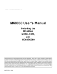
the request a pending interrupt. Figure 8-2 is a flowchart of the procedure for making an
interrupt pending.
RESET
SAMPLE AND SYNCH
IPL2-IPL0
(COMPARE INTERRUPT LEVEL
WITH STATUS REGISTER MASK)
OTHERWISE
INTERRUPT LEVEL > I2-I0,
OR TRANSITION ON LEVEL 7
ASSERT IPEND
Figure 8-2. Interrupt Pending Procedure
MOTOROLA
MC68030 USER’S MANUAL
For More Information On This Product,
Go to: www.freescale.com
8-15
Exception Processing
Freescale Semiconductor, Inc.
When several devices are connected to the same interrupt level, each device should hold
its interrupt priority level constant until its corresponding interrupt acknowledge cycle to
ensure that all requests are processed.
Table 8-4 lists the interrupt levels, the states of IPL2-IPL0 that define each level, and the
mask value that allows an interrupt at each level.
Table 8-4. Interrupt Levels and Mask Values
Freescale Semiconductor, Inc...
Requested
Interrupt Level
0*
1
2
3
4
5
6
7
Control Line Status
IP2
High
High
High
High
Low
Low
Low
Low
IP1
High
High
Low
Low
High
High
Low
Low
IP0
High
Low
High
Low
High
Low
High
Low
Interrupt Mask Level
Required for Recognition
N/A*
0
0-1
0-2
0-3
0-4
0-5
0-7
*Indicates that no interrupt is requested.
Priority level 7, the nonmaskable interrupt (NMI), is a special case. Level 7 interrupts cannot
be masked by the interrupt priority mask, and they are transition sensitive. The processor
recognizes an interrupt request each time the external interrupt request level changes from
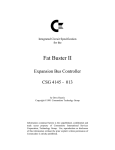
some lower level to level 7, regardless of the value in the mask. Figure 8-3 shows two
examples of interrupt recognitions, one for level 6 and one for level 7. When the MC68030
processes a level 6 interrupt, the status register mask is automatically updated with a value
of 6 before entering the handler routine so that subsequent level 6 interrupts are masked.
Provided no instruction that lowers the mask value is executed, the external request can be
lowered to level 3 and then raised back to level 6 and a second level 6 interrupt is not
processed. However, if the MC68030 is handling a level 7 interrupt (status register mask set
to 7) and the external request is lowered to level 3 and than raised back to level 7, a second
level 7 interrupt is processed. The second level 7 interrupt is processed because the level 7
interrupt is transition sensitive. A level 7 interrupt is also generated by a level comparison if
the request level and mask level are at seven and the priority mask is then set to a lower
level (with the MOVE to SR or RTE instruction, for example). As shown in Figure 8-3 for level
6 interrupt request level and mask level, this is the case for all interrupt levels.
8-16
MC68030 USER’S MANUAL
For More Information On This Product,
Go to: www.freescale.com
MOTOROLA
Freescale Semiconductor, Inc.
EXTERNAL IPL2-IPL0
SR MASK (I2-I0)
Exception Processing
ACTION
LEVEL 6 EXAMPLE:
Freescale Semiconductor, Inc...
100 ($3)
101 ($5)
INITIAL CONDITIONS
IF
001 ($6)
THEN
110 ($6)
AND
LEVEL 6 INTERRUPT (LEVEL COMPARISON)
IF
100 ($3)
AND STILL
110 ($6)
THEN
NO ACTION
IF
001 ($6)
AND STILL
110 ($6)
THEN
NO ACTION
IF STILL
001 ($6)
AND RTE SO THAT
101 ($5)
THEN
LEVEL 6 INTERRUPT (LEVEL COMPARISON)
LEVEL 7 EXAMPLE:
100 ($3)
101 ($5)
INITIAL CONDITIONS
IF
000 ($7)
THEN
111 ($7)
AND
LEVEL 7 INTERRUPT (TRANSITION)
IF
100 ($3)
AND STILL
111 ($7)
THEN
NO ACTION
IF
000 ($7)
AND STILL
111 ($7)
THEN
LEVEL 7 INTERRUPT (TRANSITION)
IF STILL
000 ($7)
AND RTE SO THAT
101 ($5)
THEN
LEVEL 7 INTERRUPT
(LEVEL COMPARISON)
Figure 8-3. Interrupt Recognition Examples
Note that a mask value of 6 and a mask value of 7 both inhibit request levels 1-6 from being
recognized. In addition, neither masks a transition to an interrupt request level of 7. The only
difference between mask values of 6 and 7 occurs when the interrupt request level is 7 and
the mask value is 7. If the mask value is lowered to 6, a second level 7 interrupt is
recognized.
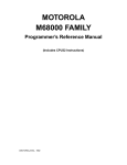
The MC68030 asserts the interrupt pending signal (IPEND) when it makes an interrupt
request pending. Figure 8-4 shows the assertion of IPEND relative to the assertion of an
interrupt level on the IPL lines. IPEND signals to external devices that an interrupt exception
will be taken at an upcoming instruction boundary (following any higher priority exception).
MOTOROLA
MC68030 USER’S MANUAL
For More Information On This Product,
Go to: www.freescale.com
8-17
Exception Processing
Freescale Semiconductor, Inc.
CLK
IPL2-IPL0
IPEND
ASSERT IPEND
IPLs RECOGNIZED
Freescale Semiconductor, Inc...
IPLs SYNCHRONIZED
COMPARE REQUEST
WITH MASK IN SR
Figure 8-4. Assertion of IPEND
The state of the IPEND signal is internally checked by the processor once per instruction,
independently of bus operation. In addition, it is checked during the second instruction
prefetch associated with exception processing. Figure 8-5 is a flowchart of the interrupt
recognition and associated exception processing sequence.
To predict the instruction boundary during which a pending interrupt is processed, the timing
relationship between the assertion of IPEND for that interrupt and the assertion of STATUS
must be examined. Figure 8-6 shows two examples of interrupt recognition. The first
assertion of STATUS after IPEND is denoted as STAT0. The next assertion of STATUS is
denoted as STAT1. If STAT0 begins on the falling edge of the clock immediately following
the clock edge that caused IPEND to assert (as shown in example 1), STAT1 is at least two
clocks long, and, when there are no other pending exceptions, the interrupt is acknowledged
at the boundary defined by STAT1. If IPEND is asserted with more setup time to STAT0, the
interrupt may be acknowledged at the boundary defined by STAT0 (as shown in example
2). In that case, STAT0 is asserted for two clocks, signaling this condition.
If no higher priority interrupt has been synchronized, the IPEND signal is negated during
state 0 (S0) of an interrupt acknowledge cycle (refer to 7.4.1.1 Interrupt Acknowledge
Cycle — Terminated Normally), and the IPLx signals for the interrupt being acknowledged
can be negated at this time.
8-18
MC68030 USER’S MANUAL
For More Information On This Product,
Go to: www.freescale.com
MOTOROLA
Freescale Semiconductor, Inc.
Exception Processing
ONCE PER INSTRUCTION
(CHECK RELATIONSHIP BETWEEN IPEND AND STATUS)
OTHERWISE
IPEND BEFORE STATUS
STAT0
STAT1
➧
➧
EXIT
THIS INSTRUCTION BOUNDARY
NEXT INSTRUCTION BOUNDARY
Freescale Semiconductor, Inc...
WAIT FOR STAT0 OR STAT1*
INDICATE INTERRUPT TO BE PROCESSED
(ASSERT STATUS FOR 2 CLOCKS)
*EXPLAINED FURTHER IN TEXT
NEGATE IPEND
EXECUTE INTERRUPT
ACKNOWLEDGE CYCLE
➧
➧
➧
TEMP SR
1
S
T0,T1
0
UPDATE 12-10
➧
➧
-(SP) TEMP
-(SP) PC
-(SP) FORMAT WORD
-(SP) OTHER EXCEPTION-DEPENDENT
INFORMATION
➧
➧
THESE
INDIVIDUAL
BUS CYCLES
MAY OCCUR
IN ANY ORDER
M=1
TEMP
M
➧
➧
➧
PC
M=0
VECTOR TABLE ENTRY
SR
0
PREFETCH 3 WORDS
END OF EXCEPTION PROCESSING
FOR THE INTERRUPT
BEGIN EXECUTION OF THE INTERRUPT
HANDLER ROUTINE OR PROCESS A
HIGHER PRIORITY EXCEPTION
Figure 8-5. Interrupt Exception Processing Flowchart
MOTOROLA
MC68030 USER’S MANUAL
For More Information On This Product,
Go to: www.freescale.com
8-19
Exception Processing
Freescale Semiconductor, Inc.
CLK
IPEND
STATUS
STAT0
STAT1
PROCEED TO INTERRUPT
EXCEPTION PROCESSING
Freescale Semiconductor, Inc...
EXAMPLE 1: INTERRUPT EXCEPTION SIGNALED DURING STAT1
CLK
IPEND
STATUS
STAT1
PROCEED TO INTERRUPT
EXCEPTION PROCESSING
EXAMPLE 2: INTERRUPT EXCEPTION SIGNALED DURING STAT0
Figure 8-6. Examples of Interrupt Recognition and Instruction Boundaries
When processing an interrupt exception, the processor first makes an internal copy of the
status register, sets the privilege level to supervisor, suppresses tracing, and sets the
processor interrupt mask level to the level of the interrupt being serviced. The processor
attempts to obtain a vector number from the interrupting device using an interrupt
acknowledge bus cycle with the interrupt level number output on pins A1–A3 of the address
bus. For a device that cannot supply an interrupt vector, the autovector signal (AVEC) can
be asserted, and the MC68030 uses an internally generated autovector, which is one of
vector numbers 25-31, that corresponds to the interrupt level number. If external logic
indicates a bus error during the interrupt acknowledge cycle, the interrupt is considered
spurious, and the processor generates the spurious interrupt vector number, 24. Refer to
7.4.1 Interrupt Acknowledge Bus Cycles for complete interrupt bus cycle information.
8-20
MC68030 USER’S MANUAL
For More Information On This Product,
Go to: www.freescale.com
MOTOROLA
Freescale Semiconductor, Inc.
Exception Processing
Freescale Semiconductor, Inc...
Once the vector number is obtained, the processor saves the exception vector offset,
program counter value, and the internal copy of the status register on the active supervisor
stack. The saved value of the program counter is the logical address of the instruction that
would have been executed had the interrupt not occurred. If the interrupt was acknowledged
during the execution of a coprocessor instruction, further internal information is saved on the
stack so that the MC68030 can continue executing the coprocessor instruction when the
interrupt handler completes execution.
If the M bit of the status register is set, the processor clears the M bit and creates a
throwaway exception stack frame on top of the interrupt stack as part of interrupt exception
processing. This second frame contains the same program counter value and vector offset
as the frame created on top of the master stack, but has a format number of 1 instead of 0
or 9. The copy of the status register saved on the throwaway frame is exactly the same as
that placed on the master stack except that the S bit is set in the version placed on the
interrupt stack. (It may or may not be set in the copy saved on the master stack.) The
resulting status register (after exception processing) has the S bit set and the M bit cleared.
The processor loads the address in the exception vector into the program counter, and
normal instruction execution resumes after the required prefetches for the interrupt handler
routine.
Most M68000 Family peripherals use programmable interrupt vector numbers as part of the
interrupt request/acknowledge mechanism of the system. If this vector number is not
initialized after reset and the peripheral must acknowledge an interrupt request, the
peripheral usually returns the vector number for the uninitialized interrupt vector, 15.
8.1.10 MMU Configuration Exception
When the MC68030 executes a PMOVE instruction that attempts to move invalid data into
the TC, CRP, or SRP register of the MMU, the PMOVE instruction causes an MMU
configuration exception. The exception is a post-instruction exception; it is processed after
the instruction completes. The processor generates exception vector number 56 when an
MMU configuration exception occurs. Refer to Section 9 Memory Management Unit for a
description of the valid configurations for the MMU registers.
MOTOROLA
MC68030 USER’S MANUAL
For More Information On This Product,
Go to: www.freescale.com
8-21
Exception Processing
Freescale Semiconductor, Inc.
The processor copies the status register, enters the supervisor privilege level, and clears
the trace bits. The processor saves the vector offset, the scanPC value (which points to the
next instruction), and the copy of the status register on the supervisor stack. It also saves
the logical address of the PMOVE instruction on the stack. Then the processor resumes
normal instruction execution after the required prefetches from the address in the exception
vector.
Freescale Semiconductor, Inc...
8.1.11 Breakpoint Instruction Exception
To use the MC68030 in a hardware emulator, it must provide a means of inserting
breakpoints in the emulator code and of performing appropriate operations at each
breakpoint. For the MC68000 and MC68008, this can be done by inserting an illegal
instruction at the breakpoint and detecting the illegal instruction exception from its vector
location. However, since the vector base register on the MC68010, MC68020, and
MC68030 allows arbitrary relocation of exception vectors, the exception address cannot
reliably identify a breakpoint. The MC68020 and MC68030 processors provide a breakpoint
capability with a set of breakpoint instructions, $4848-$484F, for eight unique breakpoints.
The breakpoint facility also allows external hardware to monitor the execution of a program
residing in the on-chip instruction cache without severe performance degradation.
When the MC68030 executes a breakpoint instruction, it performs a breakpoint
acknowledge cycle (read cycle) from CPU space type $0 with address lines A2-A4
corresponding to the breakpoint number. Refer to Figure 7-44 for the CPU space type $0
addresses and to 7.4.2 Breakpoint Acknowledge Cycle for a description of the breakpoint
acknowledge cycle. The external hardware can return either BERR, DSACKx, or STERM
with an instruction word on the data bus. If the bus cycle terminates with BERR, the
processor performs illegal instruction exception processing. If the bus cycle terminates with
DSACKx or STERM, the processor uses the data returned to replace the breakpoint
instruction in the internal instruction pipe and begins execution of that instruction. The
remainder of the pipe remains unaltered. In addition, no stacking or vector fetching is
involved with the execution of the instruction. Figure 8-7 is a flowchart of the breakpoint
instruction execution.
8-22
MC68030 USER’S MANUAL
For More Information On This Product,
Go to: www.freescale.com
MOTOROLA
Freescale Semiconductor, Inc.
Exception Processing
ENTRY
➧
➧
A4-A2
A19-A16 $0
BREAKPOINT NUMBER
CYCLE TERMINATED WITH
DSACKx OR STERM
➧
Freescale Semiconductor, Inc...
INITIATE READ BUS CYCLE
PIPE STAGE D INSTRUCTION WORD ON DATA BUS
EXECUTE INSTRUCTION WORD
BERR
TAKE ILLEGAL INSTRUCTION
EXCEPTION
EXIT
Figure 8-7. Breakpoint Instruction Flowchart
8.1.12 Multiple Exceptions
When several exceptions occur simultaneously, they are processed according to a fixed
priority. Table 8-5 lists the exceptions, grouped by characteristics. Each group has a priority
from 0-4. Priority 0 has the highest priority.
As soon as the MC68030 has completed exception processing for a condition when another
exception is pending, it begins exception processing for the pending exception instead of
executing the exception handler for the original exception condition. Also, whenever a bus
error or address error occurs, its exception processing takes precedence over lower priority
exceptions and occurs immediately. For example, if a bus error occurs during the exception
processing for a trace condition, the system processes the bus error and executes its
handler before completing the trace exception processing. However, most exceptions
cannot occur during exception processing, and very few combinations of the exceptions
shown in Table 8-5 can be pending simultaneously.
MOTOROLA
MC68030 USER’S MANUAL
For More Information On This Product,
Go to: www.freescale.com
8-23
Exception Processing
Freescale Semiconductor, Inc.
Table 8-5. Exception Priority Groups
Group/Priority
0
1
2
3
Freescale Semiconductor, Inc...
4
Exception and Relative Priority
0.0 — Reset
1.0 — Address Error
1.1 — Bus Error
2.0 — BKPT #n, CHK, CHK2, cp Mid-Instruction, cp
Protocol Violation, cpTRAPcc, Divide by Zero,
RTE, TRAP #n, TRAPV, MMU Configuration
3.0 — Illegal Instruction, Line A, Unimplemented Line
F, Privilege Violation, cp Pre-Instruction
4.0 — cp Post-Instruction
4.1 — Trace
4.2 — Interrupt
Characteristics
Aborts all processing (instruction or
exception) and does not save old context.
Suspends processing (instruction or
exception) and saves internal context.
Exception processing is part of instruction
execution.
Exception processing begins before
instruction is executed.
Exception processing begins when current
instruction or previous exception processing
is completed.
0.0 is the highest priority, 4.2 is the lowest.
The priority scheme is very important in determining the order in which exception handlers
execute when several exceptions occur at the same time. As a general rule, the lower the
priority of an exception, the sooner the handler routine for that exception executes. For
example, if simultaneous trap, trace, and interrupt exceptions are pending, the exception
processing for the trap occurs first, followed immediately by exception processing for the
trace and then for the interrupt. When the processor resumes normal instruction execution,
it is in the interrupt handler, which returns to the trace handler, which returns to the trap
exception handler. This rule does not apply to the reset exception; its handler is executed
first even though it has the highest priority because the reset operation clears all other
exceptions.
8.1.13 Return from Exception
After the processor has completed exception processing for all pending exceptions, the
processor resumes normal instruction execution at the address in the vector for the last
exception processed. Once the exception handler has completed execution, the processor
must return to the system context prior to the exception (if possible). The RTE instruction
returns from the handler to the previous system context for any exception.
8-24
MC68030 USER’S MANUAL
For More Information On This Product,
Go to: www.freescale.com
MOTOROLA
Freescale Semiconductor, Inc.
Exception Processing
When the processor executes an RTE instruction, it examines the stack frame on top of the
active supervisor stack to determine if it is a valid frame and what type of context restoration
it requires. This section describes the processing for each of the stack frame types; refer to
8.3 COPROCESSOR CONSIDERATIONS for a description of the stack frame type formats.
Freescale Semiconductor, Inc...
For a normal four-word frame, the processor updates the status register and program
counter with the data read from the stack, increments the stack pointer by eight, and
resumes normal instruction execution.
For the throwaway four-word stack, the processor reads the status register value from the
frame, increments the active stack pointer by eight, updates the status register with the
value read from the stack, and then begins RTE processing again, as shown in Figure 8-8.
The processor reads a new format word from the stack frame on top of the active stack
(which may or may not be the same stack used for the previous operation) and performs the
proper operations corresponding to that format. In most cases, the throwaway frame is on
the interrupt stack and when the status register value is read from the stack, the S and M
bits are set. In that case, there is a normal four-word frame or a ten-word coprocessor midinstruction frame on the master stack. However, the second frame may be any format (even
another throwaway frame) and may reside on any of the three system stacks.
For the six-word stack frame, the processor restores the status register and program counter
values from the stack, increments the active supervisor stack pointer by 12, and resumes
normal instruction execution.
For the coprocessor mid-instruction stack frame, the processor reads the status register,
program counter, instruction address, internal register values, and the evaluated effective
address from the stack, restores these values to the corresponding internal registers, and
increments the stack pointer by 20. The processor then reads from the response register of
the coprocessor that initiated the exception to determine the next operation to be performed.
Refer to Section 10 Coprocessor Interface Description for details of coprocessor-related
exceptions.
For both the short and long bus fault stack frames, the processor first checks the format
value on the stack for validity. In addition, for the long stack frame, the processor compares
the version number in the stack with its own version number. The version number is located
in the most significant nibble (bits 15-12) of the word at location SP+$36 in the long stack
frame. This validity check is required in a multiprocessor system to ensure that the data is
properly interpreted by the RTE instruction. The RTE instruction also reads from both ends
of the stack frame to make sure it is accessible. If the frame is invalid or inaccessible, the
processor takes a format error or a bus error exception, respectively. Otherwise, the
processor reads the entire frame into the proper internal registers, deallocates the stack,
and resumes normal processing. Once the processor begins to load the frame to restore its
internal state, the assertion of the BERR signal causes the processor to enter the halted
state with the continuous assertion of the STATUS signal. Refer to 8.2 Bus Fault Recovery
for a description of the processing that occurs after the frame is read into the internal
registers.
MOTOROLA
MC68030 USER’S MANUAL
For More Information On This Product,
Go to: www.freescale.com
8-25
Exception Processing
Freescale Semiconductor, Inc.
ENTRY
➧
TEMP (SP) +
READ FORMAT WORD
TEMP
SP + 6
OTHERWISE
FORMAT CODE = $1
(THROWAWAY FRAME)
TAKE FORMAT
ERROR EXCEPTION
FORMAT CODE = $0 (4-WORD FRAME)
OTHERWISE
OTHER FORMATS
PC
SP
SR
➧
➧
➧
Freescale Semiconductor, Inc...
INVALID FORMAT WORD
➧
➧
SR
SP
(SP) +
SP + 6
TEMP
EXIT
Figure 8-8. RTE Instruction for Throwaway Four-Word Frame
If a format error or bus error exception occurs during the frame validation sequence of the
RTE instruction, either due to any of the errors previously described or due to an illegal
format code, the processor creates a normal four-word or a bus fault stack frame below the
frame that it was attempting to use. In this way, the faulty stack frame remains intact. The
exception handler can examine or repair the faulty frame. In a multiprocessor system, the
faulty frame can be left to be used by another processor of a different type (e.g., an
MC68010, MC68020, or a future M68000 processor) when appropriate.
8-26
MC68030 USER’S MANUAL
For More Information On This Product,
Go to: www.freescale.com
MOTOROLA
Freescale Semiconductor, Inc.
Exception Processing
8.2 BUS FAULT RECOVERY
Freescale Semiconductor, Inc...
An address error exception or a bus error exception indicates a bus fault. The saving of the
processor state for a bus error or address error is described in 8.1.2 Bus Error Exception,
and the restoring of the processor state by an RTE instruction is described in 8.1.13 Return
from Exception
Processor accesses of either data items or the instruction stream can result in bus errors.
When a bus error exception occurs while accessing a data item, the exception is taken
immediately after the bus cycle terminates. Bus errors reported by the on-chip MMU are also
processed immediately. A bus error occurring during an instruction stream access is not
processed until the processor attempts to use the information (if ever) that the access should
have provided. For instruction faults, when the short format frame applies, the address of
the pipe stage B word is the value in the program counter plus four, and the address of the
stage C word is the value in the program counter plus two. For the long format, the long word
at SP+$24 contains the address of the stage B word; the address of the stage C word is the
address of the stage B word minus two. Address error faults occur only for instruction stream
accesses, and the exceptions are taken before the bus cycles are attempted.
MOTOROLA
MC68030 USER’S MANUAL
For More Information On This Product,
Go to: www.freescale.com
8-27
Exception Processing
Freescale Semiconductor, Inc.
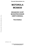
8.2.1 Special Status Word (SSW)
The internal SSW (see Figure 8-9) is one of several registers saved as part of the bus fault
exception stack frame. Both the short bus cycle fault format and the long bus cycle fault
format include this word at offset $A. The bus cycle fault stack frame formats are described
in detail at the end of this section.
15
Freescale Semiconductor, Inc...
FC
14
FB
13
RC
12
RB
11
X
10
X
9
X
8
DF
7
RM
5
4
6
RW
SIZE
3
X
2
0
FC2FC0
FC
— Fault on stage C of the instruction pipe
FB
— Fault on stage B of the instruction pipe
RC
— Rerun flag for stage C of the instruction pipe*
RB
— Rerun flag for stage B of the instruction pipe*
DF
— Fault/rerun flag for data cycle*
RM
— Read-modify-write on data cycle
RW
— Read/write for data cycle — 1=read, 0=write
SIZE
— Size code for data cycle
FC2-FC0
— Address space for data cycle
*1=Rerun Faulted bus Cycle, or run pending prefetch
0=Do not rerun bus sycle
X=For internal use only
Figure 8-9. Special Status Word (SSW)
The SSW information indicates whether the fault was caused by an access to the instruction
stream, data stream, or both. The high-order half of the SSW contains two status bits each
for the B and C stages of the instruction pipe. The fault bits (FB and FC) indicate that the
processor attempted to use a stage (B or C) and found it to be marked invalid due to a bus
error on the prefetch for that stage. The fault bits can be used by a bus error handler to
determine the cause(s) of a bus error exception. The rerun flag bits (RB and RC) are set to
indicate that a fault occurred during a prefetch for the corresponding stage. A rerun bit is
always set when the corresponding fault bit is set. The rerun bits indicate that the word in a
stage of the instruction pipe is invalid, and the state of the bits can be used by a handler to
repair the values in the pipe after an address error or a bus error, if necessary. If a rerun bit
is set when the processor executes an RTE instruction, the processor may execute a bus
cycle to prefetch the instruction word for the corresponding stage of the pipe (if it is required).
If the rerun and fault bits are set for a stage of the pipe, the RTE instruction automatically
reruns the prefetch cycle for that stage. The address space for the bus cycle is the program
space for the privilege level indicated in the copy of the status register on the stack. If a rerun
bit is cleared, the words on the stack for the corresponding stages of the pipe are accepted
as valid; the processor assumes that there is no prefetch pending for the corresponding
stage and that software has repaired or filled the image of the stage, if necessary.
8-28
MC68030 USER’S MANUAL
For More Information On This Product,
Go to: www.freescale.com
MOTOROLA
Freescale Semiconductor, Inc...
Freescale Semiconductor, Inc.
Exception Processing
If an address error exception occurs, the fault bits written to the stack frame are not set (they
are only set due to a bus error, as previously described), and the rerun bits alone show the
cause of the exception. Depending on the state of the pipeline, either RB and RC are both
set, or RC alone is set. To correct the pipeline contents and continue execution of the
suspended instruction, software must place the correct instruction stream data in the stage
C and/or stage B images requested by the rerun bits and clear the rerun bits. The least
significant half of the SSW applies to data cycles only. If the DF bit of the SSW is set, a data
fault has occurred and caused the exception. If the DF bit is set when the processor reads
the stack frame, it reruns the faulted data access; otherwise, it assumes that the data input
buffer value on the stack is valid for a read or that the data has been correctly written to
memory for a write (or that no data fault occurred). The RM bit of the SSW identifies a readmodify-write operation and the RW bit indicates whether the cycle was a read or write
operation. The SIZE field indicates the size of the operand access, and the FC field specifies
the address space for the data cycle. Data and instruction stream faults may be pending
simultaneously; the fault handler should be able to recognize any combination of the FC, FB,
RC, RB, and DF bits.
8.2.2 Using Software to Complete the Bus Cycles
One method of completing a faulted bus cycle is to use a software handler to emulate the
cycle. This is the only method for correcting address errors. The handler should emulate the
faulted bus cycle in a manner that is transparent to the instruction that caused the fault. For
instruction stream faults, the handler may need to run bus cycles for both the B and C stages
of the instruction pipe. The RB and RC bits identify the stages that may require a bus cycle;
the FB and FC bits indicate that a stage was invalid when an attempt was made to use its
contents. Those stages must be repaired. For each faulted stage, the software handler
should copy the instruction word from the proper address space as indicated by the S bit of
the copy of the status register saved on the stack to the image of the appropriate stage in
the stack frame. In addition, the handler must clear the rerun bit associated with the stage
that it has corrected. The handler should not change the fault bits FB and FC.
MOTOROLA
MC68030 USER’S MANUAL
For More Information On This Product,
Go to: www.freescale.com
8-29
Exception Processing
Freescale Semiconductor, Inc.
Freescale Semiconductor, Inc...
To repair data faults (indicated by DF=1), the software should first examine the RM bit in the
SSW to determine if the fault was generated during a read-modify-write operation. If RM=0,
the handler should then check the R/W bit of the SSW to determine if the fault was caused
by a read or a write cycle. For data write faults, the handler must transfer the properly sized
data from the data output buffer (DOB) on the stack frame to the location indicated by the
data fault address in the address space defined by the SSW. (Both the DOB and the data
fault address are part of the stack frame at SP+$18 and SP+$10, respectively.) Data read
faults only generate the long bus fault frame and the handler must transfer properly sized
data from the location indicated by the fault address and address space to the image of the
data input buffer (DIB) at location SP+$2C of the long format stack frame. Byte, word, and
3-byte[lz operands are right-justified in the 4-byte data buffers. In addition, the software
handler must clear the DF bit of the SSW to indicate that the faulted bus cycle has been
corrected.
To emulate a read-modify-write cycle, the exception handler must first read the operation
word at the program counter address (SP+2 of the stack frame). This word identifies the
CAS, CAS2, or TAS instruction that caused the fault. Then the handler must emulate this
entire instruction (which may consist of up to four long word transfers) and update the
condition code portion of the status register appropriately, because the RTE instruction
expects the entire operation to have been completed if the RM bit is set and the DF bit is
cleared. This is true even if the fault occurred on the first read cycle.
To emulate the entire instruction, the handler must save the data and address registers for
the instruction (with a MOVEM instruction, for example). Next, the handler reads and
modifies (if necessary) the memory location. It clears the DF bit in the SSW of the stack
frame and modifies the condition codes in the status register copy and the copies of any data
or address registers required for the CAS and CAS2 instructions. Last, the handler restores
the registers that it saved at the beginning of the emulation. Except for the data input buffer
(DIB), the copy of the status register, and the SSW, the handler should not modify a bus fault
stack frame. The only bits in the SSW that may be modified are DF, RB, and RC; all other
bits, including those defined for internal use, must remain unchanged.
Address error faults must be repaired in software. Address error faults can be distinguished
from bus error faults by the value in the vector offset field of the format word.
8-30
MC68030 USER’S MANUAL
For More Information On This Product,
Go to: www.freescale.com
MOTOROLA
Freescale Semiconductor, Inc.
Exception Processing
8.2.3 Completing the Bus Cycles with Rte
Freescale Semiconductor, Inc...
Another method of completing a faulted bus cycle is to allow the processor to rerun the bus
cycles during execution of the RTE instruction that terminates the exception handler. This
method cannot be used to recover from address errors. The RTE instruction is always
executed. Unless the handler routine has corrected the error and cleared the fault (and
cleared the rerun and DF bits of the SSW), the RTE instruction can complete the bus
cycle(s). If the DF bit is still set at the time of the RTE execution, the faulted data cycle is
rerun by the RTE instruction. If the fault bit for a stage of the pipe is set and the
corresponding rerun bit was not cleared by the software, the RTE reruns the associated
instruction prefetch. The fault occurs again unless the cause of the fault, such as a nonresident page in a virtual memory system, has been corrected. If the rerun bit is set for a
stage of the pipe and the fault bit is cleared, the associated prefetch cycle may or may not
be run by the RTE instruction (depending on whether the stage is required).
If a fault occurs when the RTE instruction attempts to rerun the bus cycle(s), the processor
creates a new stack frame on the supervisor stack after deallocating the previous frame, and
address error or bus error exception processing starts in the normal manner.
The read-modify-write operations of the MC68030 can also be completed by the RTE
instruction that terminates the handler routine. The rerun operation, executed by the RTE
instruction with the DF bit of the SSW set, reruns the entire instruction. If the cause of the
error has been corrected, the handler does not need to emulate the instruction but can leave
the DF bit set and execute the RTE instruction.
Systems programmers and designers should be aware that the MMU of the MC68030 treats
any bus cycle with RMC asserted as a write operation for protection checking, regardless of
the state of R/W signal. Otherwise, the potential for partially destroying system pointers with
CAS and CAS2 instructions exists since one portion of the write operation could take place
and the remainder be aborted by a bus error.
MOTOROLA
MC68030 USER’S MANUAL
For More Information On This Product,
Go to: www.freescale.com
8-31
Exception Processing
Freescale Semiconductor, Inc.
8.3 COPROCESSOR CONSIDERATIONS
Freescale Semiconductor, Inc...
Exception handler programmers should consider carefully whether to save and restore the
context of a coprocessor at the beginning and end of handler routines for exceptions that
can occur during the execution of a coprocessor instruction (i.e., bus errors, interrupts, and
coprocessor-related exceptions). The nature of the coprocessor and the exception handler
routine determines whether or not saving the state of one or more coprocessors with the
cpSAVE and cpRESTORE instructions is required. If the coprocessor allows multiple
coprocessor instructions to be executed concurrently, it may require its state to be saved
and restored for all coprocessor-generated exceptions, regardless of whether or not the
coprocessor is accessed during the handler routine. The MC68882 floating-point
coprocessor is an example of this type of coprocessor. On the other hand, the MC68881
floating-point coprocessor requires FSAVE and FRESTORE instructions within an
exception handler routine only if the exception handler itself uses the coprocessor.
8.4 EXCEPTION STACK FRAME FORMATS
The MC68030 provides six different stack frames for exception processing. The set of
frames includes the normal four- and six-word stack frames, the four-word throwaway stack
frame, the coprocessor mid-instruction stack frame, and the short and long bus fault stack
frames.
When the MC68030 writes or reads a stack frame, it uses long-word operand transfers
wherever possible. Using a long-word-aligned stack pointer with memory that is on a 32-bit
port greatly enhances exception processing performance. The processor does not
necessarily read or write the stack frame data in sequential order.
The system software should not depend on a particular exception generating a particular
stack frame. For compatibility with future devices, the software should be able to handle any
type of stack frame for any type of exception.
Table 8-6 summarizes the stack frames defined for the M68000 Family.
8-32
MC68030 USER’S MANUAL
For More Information On This Product,
Go to: www.freescale.com
MOTOROLA
Freescale Semiconductor, Inc.
Exception Processing
Freescale Semiconductor, Inc...
Exception Stack Frames (Sheet 1 of 2).
MOTOROLA
MC68030 USER’S MANUAL
For More Information On This Product,
Go to: www.freescale.com
8-33
Exception Processing
Freescale Semiconductor, Inc.
Freescale Semiconductor, Inc...
Table 8-5. Exception Stack Frames (Sheet 2 of 2).
8-34
MC68030 USER’S MANUAL
For More Information On This Product,
Go to: www.freescale.com
MOTOROLA
Freescale Semiconductor, Inc.
Freescale Semiconductor, Inc...
SECTION 9
MEMORY MANAGEMENT UNIT
The MC68030 includes a memory management unit (MMU) that supports a demand-paged
virtual memory environment. The memory management is "demand in that programs do not
specify required memory areas in advance, but request them by accessing logical
addresses. The physical memory is paged, meaning that it is divided into blocks of equal
size called page frames. The logical address space is divided into pages of the same size.
The operating system assigns pages to page frames as they are required to meet the needs
of programs.
The principal function of the MMU is the translation of logical addresses to physical
addresses using translation tables stored in memory. The MMU contains an address
translation cache (ATC) in which recently used logical-to-physical address translations are
stored. As the MMU receives each logical address from the CPU core, it searches the ATC
for the corresponding physical address. When the translation is not in the ATC, the
processor searches the translation tables in memory for the translation information. The
address calculations and bus cycles required for this search are performed by microcode
and dedicated logic in the MC68030. In addition, the MMU contains two transparent
translation registers (TT0 and TT1) that identify blocks of memory that can be accessed
without translation. The features of the MMU are:
• 32-Bit Logical Address Translated to 32-Bit Physical Address with 3-Bit Function Code
• Supports Two-Clock Cycle Processor Accesses to Physical Address Spaces
• Addresses Translated in Parallel with Accesses to Data and Instruction Caches
• On-Chip Fully Associative 22-Entry ATC
• Translation Table Search Controlled by Microcode
• Eight Page Sizes: 256, 512, 1K, 2K, 4K, 8K, 16K and 32K Bytes
• Separate User and Supervisor Translation Table Trees Are Supported
• Two Independent Blocks Can Be Defined as Transparent (Untranslated)
• Multiple Levels of Translation Tables
MOTOROLA
MC68030 USER’S MANUAL
For More Information On This Product,
Go to: www.freescale.com
9-1
Memory Management Unit
Freescale Semiconductor, Inc.
• 0-15 Upper Logical Address Bits Can Be Ignored (Using Initial Shift)
• Portions of Tables Can Be Undefined (Using Limits)
• Write Protection and Supervisor Protection
• History Bits Automatically Maintained in Page Descriptors
• Cache Inhibit Output (CIOUT) Signal Asserted on Page Basis
• External Translation Disable Input Signal (MMUDIS)
• Subset of Instruction Set Defined by MC68851
Freescale Semiconductor, Inc...
The MMU completely overlaps address translation time with other processing activity when
the translation is resident in the ATC. ATC accesses operate in parallel with the on-chip
instruction and data caches.
Figure 9-1 is a block diagram of the MC68030 showing the relationship of the MMU to the
execution unit and the bus controller. For an instruction or operand access, the MC68030
simultaneously searches the caches and searches for a physical address in the ATC. If the
translation is available, the MMU provides the physical address to the bus controller and
allows the bus cycle to continue. When the instruction or operand is in either of the on-chip
caches on a read cycle, the bus controller aborts the bus cycle before address strobe is
asserted. Similarly, the MMU causes a bus cycle to abort before the assertion of address
strobe when a valid translation is not available in the ATC or when an invalid access is
attempted.
An MMU disable input signal (MMUDIS) is provided that dynamically disables address
translation for emulation, diagnostic, or other purposes.
The programming model of the MMU (see Figure 9-2) consists of two root pointer registers,
a control register, two transparent translation registers, and a status register. These
registers can only be accessed by supervisor programs. The CPU root pointer register
points to an address translation tree structure in memory that describes the logical-tophysical mapping for user accesses or for both user and supervisor accesses. The
supervisor root pointer register optionally points to an address translation tree structure for
supervisor mappings. The translation control register is comprised of fields that control the
translation operation. Each transparent translation register can define a block of logical
addresses that are used as physical addresses (without translation). The MMU status
register contains accumulated status information from a translation performed as a part of a
PTEST instruction.
9-2
MC68030 USER’S MANUAL
For More Information On This Product,
Go to: www.freescale.com
MOTOROLA
MOTOROLA
ADDRESS
BUS
ADDRESS
PADS
MC68030 USER’S MANUAL
For More Information On This Product,
Go to: www.freescale.com
ADDRESS
BUS
PREFETCH PENDING
BUFFER
BUS CONTROL
SIGNALS
MICROBUS
CONTROLLER
WRITE PENDING
BUFFER
BUS CONTROLLER
ACCESS
CONTROL
UNIT
ADDRESS
INSTRUCTION
ADDRESS
BUS
CONTROL
LOGIC
CONTROL
STORE
DATA
ADDRESS
BUS
PROGRAM
COUNTER
SECTION
STAGE
C
CACHE
HOLDING
REGISTER
(CAHR)
DATA
CACHE
MISALIGNMENT
MULTIPLEXER
DATA
SECTION
INSTRUCTION
CACHE
STAGE
B
INSTRUCTION PIPE
ADDRESS
SECTION
STAGE
D
EXECUTION UNIT
MICROSEQUENCER AND
CONTROL
Freescale Semiconductor, Inc...
SIZE
MULTIPLEXER
INTERNAL
DATA
BUS
DATA
PADS
DATA
BUS
Freescale Semiconductor, Inc.Memory Management Unit
Figure 9-1. MMU Block Diagram
9-3
Memory Management Unit
Freescale Semiconductor, Inc.
31
0
ACCESS CONTROL 0
31
0
ACCESS CONTROL 1
15
0
Freescale Semiconductor, Inc...
ACU STATUS (ACUSR)
FIG. 9-2
Figure 9-2. MMU Programming Model
The ATC in the MMU is a fully associative cache that stores 22 logical-to-physical address
translations and associated page information. It compares the logical address and function
code internally supplied by the processor with all tag entries in the ATC. When the access
address and function code matches a tag in the ATC (a hit occurs) and no access violation
is detected, the ATC outputs the corresponding physical address to the bus controller, which
continues the external bus cycle. Function codes are routed to the bus controller unmodified.
Each ATC entry contains a logical address, a physical address, and status bits. Among the
status bits are the write protect and cache inhibit bits.
When the ATC does not contain the translation for a logical address (a miss occurs) and an
external bus cycle is required, the MMU aborts the access and causes the processor to
initiate bus cycles that search the translation tables in memory for the correct translation. If
the table search completes without any errors, the MMU stores the translation in the ATC
and provides the physical address for the access, allowing the bus controller to retry the
original bus cycle.
An MMU translation table has a tree structure with the base of the first table defined by a
root pointer descriptor. The root pointer descriptor of the current translation table is resident
in one of two root pointer registers. The general tree structure is shown in Figure 9-3. Table
entries at the upper levels of a tree point to other tables. The table leaf entries are page
frame addresses. All addresses stored in the translation tables are physical addresses; the
translation tables reside in the physical address space.
System software selects the parameters for the translation tables by configuring the
translation control register (TC) appropriately. The function codes or a portion of the logical
address can be defined as the index into the first level of lookup in the table. The TC register
specifies how many bits of the logical address are used as the index for each level of the
lookup (as many as 15 bits can be used at a given level).
9-4
MC68030 USER’S MANUAL
For More Information On This Product,
Go to: www.freescale.com
MOTOROLA
Freescale Semiconductor, Inc.Memory Management Unit
31
24
23
ADDRESS BASE
E
15
0
0
0
0
16
ADDRESS MASK
CI
R/W RWN
8
0
FC BASE
0
7
FC MASK
0
ADDRESS BASE - VALUE OF A31-A24 THAT DEFINES BLOCK
ADDRESS MASK - BITS A31-A24 TO BE IGNORED
Freescale Semiconductor, Inc...
E - ENABLE
CI - CACHE INHIBIT
R/W - READ/WRITE
RWM - READ WRITE MASK
FC BASE - FUNCTION CODE VALUE FOR BLOCK
FC MASK - FUNCTION CODE BITS TO BE IGNORED
FIG 9-3
Figure 9-3. Translation Table Tree
MOTOROLA
MC68030 USER’S MANUAL
For More Information On This Product,
Go to: www.freescale.com
9-5
Memory Management Unit
Freescale Semiconductor, Inc.
9.1 TRANSLATION TABLE STRUCTURE
Freescale Semiconductor, Inc...
The M68030 uses the ATC and translation tables stored in memory to perform the
translation from a logical to a physical address. Translation tables for a program are loaded
into memory by the operating system.
The general translation table structure supported by the MC68030 is a tree structure of
tables. The pointer tables form the branches of the tree. These tables contain the base
addresses of other tables. Page descriptors can reside in pointer tables and, in that case,
are called early termination descriptors. The tables at the leaves of the tree are called page
tables. Only a portion of the translation table for the entire logical address space is required
to be resident in memory at any time: specifically, only the portion of the table that translates
the logical addresses that the currently executing process(es) use(s) must be resident.
Portions of translation tables can be dynamically allocated as the process requires
additional memory.
As shown in Figure 9-4, the root pointer for a table is a descriptor that contains the base
address of the top level table for the tree. The pointer tables and page tables also consist of
descriptors. A descriptor in a pointer table typically contains the base address of a table at
the next level of the tree. A table descriptor can also contain limits for the index into the next
table, protection information, and history information pertaining to the descriptor. Each table
is indexed by a field extracted from the logical address. In the example shown in Figure 94, the A field of the logical address, $00A, is added to the root pointer value to select a
descriptor at the A level of the translation tree. The selected descriptor points to the base of
the appropriate page table, and the B field of the logical address ($006) is added to this base
address to select a descriptor within the page table. A descriptor in a page table contains
the physical base address of the page, protection information, and history information for the
page. A page descriptor can also reside in a pointer table or even in a root pointer to define
a contiguous block of pages. A two-level page task is shown. The 32-bit logical address
space is divided into 4096 segments of 1024 bytes each.
Figure 9-5 shows a possible layout of this example translation tree in memory.
9-6
MC68030 USER’S MANUAL
For More Information On This Product,
Go to: www.freescale.com
MOTOROLA
Freescale Semiconductor, Inc.Memory Management Unit
15
7
6
5
0
AC
AC - ACCESS CONTROLLED
FIG 9-4
Freescale Semiconductor, Inc...
Figure 9-4. Example Translation Table Tree
MOTOROLA
MC68030 USER’S MANUAL
For More Information On This Product,
Go to: www.freescale.com
9-7
Memory Management Unit
Freescale Semiconductor, Inc.
(UNABLE TO LOCATE ART)
Figure 9-5. Example Translation Tree Layout in Memory
Freescale Semiconductor, Inc...
9.1.1 Translation Control
The translation control register (TC) defines the size of pages in memory, selects the root
pointer register to be used for supervisor accesses, indicates whether the top level of the
translation tree is indexed by function code, and specifies the number of logical address bits
used to index into the various levels of the translation tree. The initial shift (IS) field of the
TC register defines the size of the logical address space; it contains the number of most
significant address bits that are ignored in the translation table lookup. For example, if the
IS field is set to zero, the logical address space is 232 bytes. On the other hand, if the IS field
is set to 15, the logical address space contains only 232—21 bytes.
The page size (PS) field of the TC register specifies the page size for the system. The
number of pages in the system is equal to the logical address space divided by the page
size. The maximum number of pages that can be defined by a translation tree is greater than
16 million (232/28). The minimum number is 4 (217/215). The function code can also be used
in the table lookup, defining as many as seven regions of the above size (FC=0-6). The
entire range of the logical address space(s) can be defined by translation tables of many
sizes. The MC68030 provides flexibility that simplifies the implementation of large
translation tables.
The use of a tree structure with as many as five levels of tables provides granularity in
translation table design. The LIMIT field of the root pointer can limit the value of the first
index and limits the actual number of descriptors required. Optionally, the top level of the
structure can be indexed by function code bits. In this case, the pointer table at this level
contains eight descriptors. The next level of the structure (or the top level when the FCL bit
of the TC register is set to zero) is indexed by the most significant bits of the logical address
(disregarding the number of bits specified by the IS field). The number of logical address bits
used for this index is specified by the TIA field of the TC register. If, for example, the TIA
field contains the value 5, the index for this level contains five bits, and the pointer table at
this level contains at most 32 descriptors.
Similarly, the TIB, TIC, and TID fields of the TC register define the indexes for lower levels
of the translation table tree. When one of these fields contains zero, the remaining TIx fields
are ignored; the last nonzero TIx field defines the index into the lowest level of the tree
structure. The tables selected by the index at this level are page tables; every descriptor in
these tables is (or represents) a page descriptor. Figure 9-6 shows how the TIx fields of the
TC register apply to a function code and logical address.
(UNABLE TO LOCATE ART)
Figure 9-6. Derivation of Table Index Fields
9-8
MC68030 USER’S MANUAL
For More Information On This Product,
Go to: www.freescale.com
MOTOROLA
Freescale Semiconductor, Inc.Memory Management Unit
For example, a TC register in which the FCL bit is set to one, the TIA field contains five, the
TIB field contains nine, and the TIC and TID fields contain zero defines a three-level
translation tree. The top level is indexed by the function code, the next level by five logical
address bits, and the bottom level by nine logical address bits. If the TIC field contained nine
instead of zero, the translation tree would have four levels, and the two bottom levels would
each be indexed by 9-bit portions of the logical address.
The following equation for fields in the TC register must be satisfied:
IS+PS+TIA+TIB1+TIC1+TID1 = 32
Freescale Semiconductor, Inc...
That is, every bit of the logical address either addresses a byte within the page, is part of the
index at some level of the address table, or is explicitly ignored by initial shift.
Table 9-1 lists the valid sizes of the table indexes at each of the levels indexed by the TIx
fields and the position of each table index within the logical address. When the function code
is also used to select a descriptor, a total of five levels can be defined by the logical address.
The function code lookup level and levels B, C, and D can be suppressed.
Table 9-1. Size Restrictions
Field
A
B
C
D
Starting Bit Position
31-IS
31-IS-TIA
31-IS-TIA-TIB
31-IS-TIA-TIB-TIC
Size Restrictions
1-15 (TIA must be greater than zero; minimum of two if TIB=0)
0-15
0-15 (ignored if TIB is zero)
31-IS-TIA-TIB-TIC 0-15 (ignored if TIB or TIC is zero)
9.1.2 Translation Table Descriptors
The address translation trees consist of tables of descriptors. These descriptors can be one
of four basic types: table descriptors, page descriptors (normal or early termination), invalid
descriptors, or indirect descriptors. Each of these descriptors has both a long-format and a
short-format representation.
A root pointer descriptor defines the root of a tree and can be a table descriptor or an early
termination page descriptor. A table descriptor points to a descriptor table in memory that
defines the next lower level in the translation tree. An early termination page descriptor
causes immediate termination of the table search and contains the physical address of an
area in memory that contains page frames corresponding to contiguous logical addresses
(Refer to 9.5.3.1 Early Termination and Contiguous Memory).
1.NOTE 1: If any of these fields are zero, the remaining fields are ignored.
MOTOROLA
MC68030 USER’S MANUAL
For More Information On This Product,
Go to: www.freescale.com
9-9
Memory Management Unit
Freescale Semiconductor, Inc.
Tables at intermediate levels of a translation tree contain descriptors that are similar to the
root pointer descriptors. They can contain table descriptors or early termination page
descriptors and can also contain invalid descriptors.
Freescale Semiconductor, Inc...
The descriptor tables at the lowest level of a translation tree can only contain page
descriptors, indirect descriptors, and invalid descriptors. A page descriptor in the lowest
level of a translation tree defines the physical address of a page frame in memory that
corresponds to the logical address of a page. An indirect descriptor contains a pointer to the
actual page descriptor and can be used when a single page descriptor is accessed by two
or more logical addresses.
To enhance the flexibility of translation table design, descriptors (except for root pointer
descriptors) can be either short or long format. The short-format descriptors consist of one
long word and have no index-limiting capabilities or supervisor-only protection. The longformat descriptors consist of two long words and contain all defined descriptor fields for the
MC68030. The pointer and page tables can each contain either short- or long-format
descriptors, but no single table can contain both sizes. Tables at different levels of the
translation tree can contain different formats of descriptors. Tables at the same level can
also contain descriptors of different formats, but all descriptors in a particular pointer table
or page table must be of the same format. Figure 9-7 shows a translation tree that uses
several different format descriptors.
All descriptors contain a descriptor type (DT) field, which identifies the descriptor or specifies
the size of the descriptors in the table to which the descriptor points. It is always the two least
significant bits of the most significant (or only) long word of a descriptor.
Invalid descriptors can be used at any level of the translation tree except the root. When a
table search for a normal translation encounters an invalid descriptor, the processor takes
a bus error exception. The invalid descriptor can be used to identify either a page or branch
of the tree that has been stored on an external device and is not resident in memory or a
portion of the translation table that has not yet been defined. In these two cases, the
exception routine can either restore the page from disk or add to the translation table.
9-10
MC68030 USER’S MANUAL
For More Information On This Product,
Go to: www.freescale.com
MOTOROLA
Freescale Semiconductor, Inc.Memory Management Unit
(UNABLE TO LOCATE ART)
Figure 9-7. Example Translation Tree Using Different Format Descriptors
All long-format descriptors and short-format invalid descriptors include one or two unused
fields. The operating system can use these fields for its own purposes. For example, the
operating system can encode these fields to specify the type of invalid descriptor.
Alternately, the external device address of a page that is not resident in main memory can
be stored in the unused field.
Freescale Semiconductor, Inc...
9.2 ADDRESS TRANSLATION
The function of the MMU is to translate logical addresses to physical addresses according
to control information stored by the system in the MMU registers and in translation table
trees resident in memory.
9.2.1 General Flow for Address Translation
A CPU space address (FC0-FC2=$7) is a special case that is immediately used as a
physical address without translation. For other accesses, the translation process proceeds
as follows:
1. Search the on-chip data and instruction caches for the required instruction word or operand on read accesses.
2. Compare the logical address and function code to the transparent translation parameters in the transparent translation registers, and use the logical address as a physical
address for the memory access when one or both of the registers match.
3. Compare the logical address and function code to the tag portions of the entries in the
ATC and use the corresponding physical address for the memory access when a
match occurs.
4. When no on-chip cache hit occurs (on a read) and no TTx register matches or valid
ATC entry matches, initiate a table search operation to obtain the corresponding physical address from the corresponding translation tree, create a valid ATC entry for the
logical address, and repeat step 3.
Figure 9-8 is a general flowchart for address translation. The top branch of the flowchart
applies to CPU space accesses (FC0-FC2=$7). The next branch applies to read accesses
only. When either of the on-chip caches hits (contains the required data or instruction), no
memory access is necessary. The third branch applies to transparent translation. The
bottom three branches apply to ATC translation as follows. If the requested access misses
in the ATC, the memory cycle is aborted, and a table search operation proceeds. An ATC
entry is created after the table search, and the access is retried. If an access hits in the ATC
but a bus error was detected during the table search that created the ATC entry, the memory
access is aborted, and a bus error exception is taken.
MOTOROLA
MC68030 USER’S MANUAL
For More Information On This Product,
Go to: www.freescale.com
9-11
Memory Management Unit
Freescale Semiconductor, Inc.
Freescale Semiconductor, Inc...
(UNABLE TO LOCATE ART)
Figure 9-8. Address Translation General Flowchart
If an access results in an ATC hit but the access is either a write or read-modify-write access
and the page is write protected, the memory cycle is also aborted, and a bus error exception
is taken. For a write or read-modify-write access, when the modified bit of the ATC entry is
not set, the memory cycle is aborted, a table search proceeds to set the modified bit in both
the page descriptor in memory and in the ATC, and the access is retried. If the modified bit
of the ATC entry is set and the bus error bit is not, assuming that neither TTx register
matches and the access is not to CPU space, the ATC provides the address translation to
the bus controller under two conditions: 1) if a read access does not hit in either on-chip
cache and 2) if a write or read-modify-write access is not write protected.
The preceding description of the general flowchart specifies several conditions that cause
the memory cycle to be aborted. In these cases, the bus cycle is aborted before the
assertion of AS.
9.2.2 Effect of RESET On MMU
When the MC68030 is reset by the assertion of the RESET signal, the E bits of the TC and
TTx registers are cleared, disabling address translation. This causes logical addresses to
be passed through as physical addresses to the bus controller, allowing an operating system
to set up the translation tables and MMU registers, as required. After it has initialized the
translation tables and registers, the E bit of the TC register can be set, enabling address
translation. A reset of the processor does not invalidate any entries in the ATC. An MMU
instruction (such as PMOVE) that flushes the ATC must be executed to flush all existing
valid entries from the ATC after a reset operation and before translation is enabled.
9.2.3 Effect of MMUDIS On Address Translation
The assertion of MMUDIS prevents the MMU from performing searches of the ATC and the
execution unit from performing table searches. With address translation disabled, logical
addresses are used as physical addresses. When an initial access to a long-word-aligned
data operand that is larger than the addressed port size is performed, the successive bus
cycles for additional portions of the operand always use the same higher order address bits
that were used for the initial bus cycle (changing A0 and A1 appropriately). Thus, if MMUDIS
is asserted during this type of operation, the disabling of address translation does not
become effective until the entire transfer is complete. Note that the assertion of MMUDIS
does not affect the operation of the transparent translation registers.
9-12
MC68030 USER’S MANUAL
For More Information On This Product,
Go to: www.freescale.com
MOTOROLA
Freescale Semiconductor, Inc.Memory Management Unit
9.3 TRANSPARENT TRANSLATION
Two independent transparent translation registers (TT0 and TT1) in the MMU optionally
define two blocks of the logical address space that are directly translated to the physical
address spaces. The MMU does not explicitly check write protection for the addresses in
these blocks, but a block can be specified as transparent only for read cycles. The blocks of
addresses defined by the TTx registers include at least 16M bytes of logical address space;
the two blocks can overlap, or they can be separate.
Freescale Semiconductor, Inc...
The following description of the address comparison assumes that both TT0 and TT1 are
enabled; however, each TTx register can be independently disabled. A disabled TTx
register is completely ignored.
When the MMU receives an address to be translated, the function code and the eight highorder bits of the address are compared to the block of addresses defined by TT0 and TT1.
The address space block for each TTx register is defined by the base function code, the
function code mask, the logical base address, and the logical address mask. When a bit in
a mask field is set, the corresponding bit of the base function code or logical base address
is ignored in the function code and address comparison. Setting successively higher order
bits in the address mask increases the size of the transparently translated block.
The address for the current bus cycle and a TTx register address match when the function
code bits and address bits (not including masked bits) are equal. Each TTx register can
specify read accesses or write accesses as transparent. In that case, the internal read/write
signal must match the R/W bit in the TTx register for the match to occur. The selection of
the type of access (read or write) can also be masked. The read/write mask bit (RWM) must
be set for transparent translation of addresses used by instructions that execute readmodify-write operations. Otherwise, neither the read nor write portions of read-modify-write
operations are mapped transparently with the TTx registers, regardless of the function code
and address bits for the individual cycles within a read-modify-write operation.
MOTOROLA
MC68030 USER’S MANUAL
For More Information On This Product,
Go to: www.freescale.com
9-13
Memory Management Unit
Freescale Semiconductor, Inc.
Freescale Semiconductor, Inc...
By appropriately configuring a transparent translation register, flexible transparent mapping
can be specified. For instance, to transparently translate user program space with a TTx
register, the RWM bit of the register is set to 1, the FC BASE is set to $2, and the FC MASK
is set to $0. To transparently translate supervisor data read accesses of addresses
$00000000-$0FFFFFFF, the LOGICAL BASE ADDRESS field is set to $0X, the LOGICAL
ADDRESS MASK is set to $0F, the R/W bit is set to 1, the RWM bit is set to 0, the FC BASE
is set to $5, and the FC MASK field is set to $0. Since only read cycles are specified by the
TTx register for this example, write accesses for this address range can be translated with
the translation tables and write protection can be implemented as required.
Each TTx register can specify that the contents of logical addresses in its block should not
be stored in either an internal or external cache. The cache inhibit out signal (CIOUT) is
asserted when an address matches the address specified by a TTx register and the cache
inhibit bit in that TTx register is set. CIOUT is used by the on-chip instruction and data
caches to inhibit caching of data associated with this address. The signal is available to
external caches for the same purpose.
For an access, if either of these registers match, the access is transparently translated. If
both registers match, the CI bits are ORed together to generate the CIOUT signal.
Transparent translation can also be implemented by the translation tables of the translation
trees if the physical addresses of pages are set equal to the logical addresses.
9.4 ADDRESS TRANSLATION CACHE
The ATC is a 22-entry fully associative (content addressable) cache that contains address
translations in a form similar to the corresponding page descriptors in memory to provide
fast address translation of a recently used logical address.
The MC68030 is organized such that the translation time of the ATC is always completely
overlapped by other operations; thus, no performance penalty is associated with ATC
searches. The address translation occurs in parallel with on-chip instruction and data cache
accesses before an external bus cycle begins.
9-14
MC68030 USER’S MANUAL
For More Information On This Product,
Go to: www.freescale.com
MOTOROLA
Freescale Semiconductor, Inc.Memory Management Unit
If possible, when the ATC stores a new address translation, it replaces an entry that is no
longer valid. When all entries in the ATC are valid, the ATC selects a valid entry to be
replaced, using a pseudo least recently used algorithm. The ATC uses a validity bit and an
internal history bit to implement this replacement algorithm. ATC hit rates are application
dependent, but hit rates ranging from 98% to greater than 99% can be expected.
Each ATC entry consists of a logical address and information from a corresponding page
descriptor that contains the physical address. The 28-bit logical (or tag) portion of each entry
consists of three fields:
Freescale Semiconductor, Inc...
27
V
26
24
23
0
FC
LOGICAL ADDRESS
V — VALID
This bit indicates the validity of the entry. If V is set, this entry is valid. This bit is set
when the MC68030 loads an entry. A flush operation clears the bit. Specifically, any of
these operations clear the V bit of an entry:
• A PMOVE instruction with the FD bit equal to zero that loads a value into the CRP,
SRP, TC, TT0, or TT1 register.
• A PFLUSHA instruction.
• A PFLUSH instruction that selects this entry.
• A PLOAD instruction for a logical address and FC that matches the tag for this entry.
The instruction writes a new entry (with the V bit set) for the specified logical address.
• The selection of this entry for replacement by the replacement algorithm of the ATC.
FC — FUNCTION CODE
This 3-bit field contains the function code bits (FC0-FC2) corresponding to the logical address in this entry.
LOGICAL ADDRESS
This 24-bit field contains the most significant logical address bits for this entry. All 24 bits
of this field are used in the comparison of this entry to an incoming logical address when
the page size is 256 bytes. For larger page sizes, the appropriate number of least significant bits of this field are ignored.
MOTOROLA
MC68030 USER’S MANUAL
For More Information On This Product,
Go to: www.freescale.com
9-15
Memory Management Unit
Freescale Semiconductor, Inc.
Each logical portion of an entry has a corresponding 28-bit physical (or data) portion. The
physical portion contains these fields:
Freescale Semiconductor, Inc...
27
B
26
CI
25
WP
24
M
23
0
PHYSICAL ADDRESS
B — BUS ERROR
This bit is set for an entry if a bus error, an invalid descriptor, a supervisor violation, or a
limit violation is encountered during the table search corresponding to this entry. When B
is set, a subsequent access to the logical address causes the MC68030 to take a bus error exception. Since an ATC miss causes an immediate retry of the access after the table
search operation, the bus error exception is taken on the retry. The B bit remains set until
a PFLUSH instruction or a PLOAD instruction for this entry invalidates the entry or until
the replacement algorithm for the ATC replaces it.
CI — CACHE INHIBIT
This bit is set when the cache inhibit bit of the page descriptor corresponding to this entry
is set. When the MC68030 accesses the logical address of an entry with the CI bit set, it
asserts the cache inhibit out signal (CIOUT) during the corresponding bus cycle. This signal inhibits caching in the on-chip caches and can also be used for external caches.
WP — WRITE PROTECT
This bit is set when a WP bit is set in any of the descriptors encountered during the table
search for this entry. Setting a WP bit in a table descriptor write protects all pages accessed with that descriptor. When the WP bit is set, a write access or a read-modify-write access to the logical address corresponding to this entry causes a bus error exception to be
taken immediately.
M — MODIFIED
This bit is set when a valid write access to the logical address corresponding to the entry
occurs. If the M bit is clear and a write access to this logical address is attempted, the
MC68030 aborts the access and initiates a table search, setting the M bit in the page descriptor, invalidating the old ATC entry, and creating a new entry with the M bit set. The
MMU then allows the original write access to be performed. This assures that the first
write operation to a page sets the M bit in both the ATC and the page descriptor in the
translation tables even when a previous read operation to the page had created an entry
for that page in the ATC with the M bit clear.
9-16
MC68030 USER’S MANUAL
For More Information On This Product,
Go to: www.freescale.com
MOTOROLA
Freescale Semiconductor, Inc.Memory Management Unit
PHYSICAL ADDRESS
This 24-bit field contains the physical address bits (A31-A8) from the page descriptor corresponding to the logical address. When the page size is larger than 256 bytes, not all bits
in the physical address field are used. All page index bits of the logical address are transferred to the bus controller without translation.
9.5 TRANSLATION TABLE DETAILS
The details of translation tables and their use include detailed descriptions of the
descriptors, table searching, translation table structure variations, and the protection
techniques available with the MC68030 MMU.
Freescale Semiconductor, Inc...
9.5.1 Descriptor Details
The descriptor details include detailed descriptions of the short- and long-format descriptors
used in the translation trees. The fields that apply to all descriptors are described in the first
paragraph.
9.5.1.1 DESCRIPTOR FIELD DEFINITIONS. All descriptor fields are used in more than
one type of descriptor. This section lists these fields and describes the use of each field.
DT
This 2-bit field contains the descriptor type; the first two types apply to the descriptor itself. The other two types apply to the descriptors in the table at the next level of the tree.
The values are defined as follows:
$0 INVALID
This code identifies the current descriptor as an invalid descriptor. A table search
ends when an invalid descriptor is encountered.
$1 PAGE DESCRIPTOR
This code identifies the current descriptor as a page descriptor. The page descriptor is a normal page descriptor when it resides in a page table (in the bottom level
of the translation tree). A page descriptor at a higher level is an early termination
page descriptor. A table search ends when a page descriptor of either type is encountered.
MOTOROLA
MC68030 USER’S MANUAL
For More Information On This Product,
Go to: www.freescale.com
9-17
Memory Management Unit
Freescale Semiconductor, Inc.
$2 VALID 4 BYTE
This code specifies that the next table to be accessed contains short-format descriptors. The MC68030 multiplies the index for the next table by four to access the
next descriptor. (Short-format descriptors must be long-word aligned.) When used
in a page table (bottom level of an translation tree), this code identifies an indirect
descriptor that points to a short-format page descriptor.
Freescale Semiconductor, Inc...
$3 VALID 8 BYTE
This code specifies that the next table to be accessed contains long-format descriptors. The MC68030 multiplies the index for the next table by eight to access
the next descriptor. (Long-format descriptors must be quad-word aligned.) When
used in a page table (bottom level of an address translation tree), this code identifies an indirect descriptor that points to a long-format page descriptor.
U
This bit is automatically set by the processor when a descriptor is accessed in which the
U bit is clear except after a supervisor violation is detected. In a page descriptor table, this
bit is set to indicate that the page corresponding to the descriptor has been accessed. In
a pointer table, this bit is set to indicate that the pointer has been accessed by the
MC68030 as part of a table search. Note that a pointer may be fetched, and its U bit set,
for an address to which access is denied at another level of the tree. Updates of the U bit
are performed before the MC68030 allows a page to be accessed. The processor never
clears this bit.
WP
This bit provides write protection. The states of all WP bits encountered during a table
search are logically ORed, and the result is copied to the ATC entry at the end of a table
search for a logical address. During a table search for a PTEST instruction, the processor
copies this result into the MMU status register (MMUSR). When WP is set, the MC68030
does not allow the logical address space mapped by that descriptor to be written by any
program (i.e., this protection is absolute). If the WP bit is clear, the MC68030 allows write
accesses using this descriptor (unless access is restricted at some other level of the translation tree).
CI
This bit is set to inhibit caching of items within this page by the on-chip instruction and data
caches and, also, to cause the assertion of the CIOUT signal by the MC68030 for bus cycles accessing items within this page.
9-18
MC68030 USER’S MANUAL
For More Information On This Product,
Go to: www.freescale.com
MOTOROLA
Freescale Semiconductor, Inc.Memory Management Unit
L/U
This bit specifies the type of limit in the LIMIT field. When the L/U bit is set, the LIMIT field
contains the unsigned lower limit; the index value for the next level of the tree must be
greater than or equal to the value in the LIMIT field. When the bit is cleared, the limit is an
unsigned upper limit, and the index value must be less than or equal to the LIMIT. An outof-bounds access causes the B bit in the ATC entry for the address to be set and causes
the table search to abort.
Freescale Semiconductor, Inc...
LIMIT
This 15-bit field contains a limit to which the index portion of an address is compared to
detect an out-of-bounds index. The limit check applies to the index into the table at the
next lower level of the translation tree. If the descriptor is an early termination page descriptor, the limit field is still used as a check on the next index field of the logical address.
M
This bit identifies a modified page. The MC68030 sets the M bit in the corresponding page
descriptor before a write operation to a page for which the M bit is zero, except after a
descriptor with the WP bit set is encountered, or after a supervisor violation is encountered. An access is considered to be a write for updating purposes if either the R/W or
RMC signal is low. The MC68030 never clears this bit.
PAGE ADDRESS
This 24-bit field contains the physical base address of a page in memory. The low-order
bits of the address are supplied by the logical address. When the page size is larger than
256 bytes, one or more of the least significant bits of this field are not used. The number
of unused bits is equal to the PS field value in the TC register minus eight.
S
This bit identifies a pointer table or a page as a supervisor only table or page. When the
S bit is set, only programs operating at the supervisor privilege level are allowed to access
the portion of the logical address mapped by this descriptor. If this bit is clear, accesses
using this descriptor are not restricted to supervisor-only unless the access is restricted
by some other level of the translation tree.
TABLE ADDRESS
This 28-bit field contains the physical base address of a table of descriptors. The low-order bits of the address are supplied by the logical address.
MOTOROLA
MC68030 USER’S MANUAL
For More Information On This Product,
Go to: www.freescale.com
9-19
Memory Management Unit
Freescale Semiconductor, Inc.
DESCRIPTOR ADDRESS
This 30-bit field, which contains the physical address of a page descriptor, is only used in
short- and long-format indirect descriptors.
Freescale Semiconductor, Inc...
UNUSED
The bits in this field are not used by the MC68030 and may be used by the system software.
RESERVED
Descriptor fields designated by a one or a zero are reserved by Motorola for future definition. These bits should be consistently written as either a one or a zero as appropriate. In
the root pointers, these bits are not alterable. In memory-resident descriptors, the values
in these fields are neither checked nor altered by the MC68030. Use of these bits by system software for any purpose may not be supported in future products.
9.5.1.2 ROOT POINTER DESCRIPTOR. A root pointer descriptor contains the address of
the top-level pointer table of a translation tree. This type of descriptor is loaded into the CRP
and SRP registers with the PMOVE instruction. The field descriptions in the preceding
section apply to corresponding fields of the CRP and SRP with two minor exceptions. A
descriptor-type code of $00 (invalid) is not allowed; an attempt to load zero into the DT field
of the CRP or SRP register results in an MMU configuration exception. Also, when the FCL
field of the TC register is set, the L/U and LIMIT fields of the root pointer registers are
unused. Figure 9-9 shows the root pointer descriptor format.
(UNABLE TO LOCATE ART)
Figure 9-9. Root Pointer Descriptor Format
9.5.1.3 SHORT-FORMAT TABLE DESCRIPTOR. The field descriptions in 9.5.1.1
DESCRIPTOR FIELD DEFINITIONS apply to corresponding fields of this descriptor. Figure
9-10 shows the format of the short-format table descriptor.
(UNABLE TO LOCATE ART)
Figure 9-10. Short-Format Table Descriptor
9.5.1.4 LONG-FOMAT TABLE DESCRIPTOR. The
field
descriptions
in
9.5.1.1
DESCRIPTOR FIELD DEFINITIONS apply to corresponding fields of this descriptor. During
address computations, the MC68030 internally replaces the UNUSED field with zeros.
Figure 9-11 shows the format of the long-format table descriptor.
(UNABLE TO LOCATE ART)
Figure 9-11. Long-Format Table Descriptor
9-20
MC68030 USER’S MANUAL
For More Information On This Product,
Go to: www.freescale.com
MOTOROLA
Freescale Semiconductor, Inc.Memory Management Unit
9.5.1.5 SHORT-FORMAT EARLY TERMINATION PAGE DESCRIPTOR. The
shortformat early termination page descriptor contains the page descriptor code in the DT field
but resides in a pointer table. That is, the table in which an early termination page descriptor
is located is not at the bottom level of the address translation tree. The field descriptions in
9.5.1.1 Descriptor Field Definitions apply to corresponding fields of this descriptor. Figure
9-12 shows the format of the short-format early termination page descriptor.
Freescale Semiconductor, Inc...
(UNABLE TO LOCATE ART)
Figure 9-12. Short-Format Page Descriptor and
Short-Format Early Termination Page Descriptor
9.5.1.6 LONG-FORMAT EARLY TERMINATION PAGE DESCRIPTOR. The long-format
early termination page descriptor contains the page descriptor code in the DT field but
resides in a pointer table like the short-format early termination page descriptor. The field
descriptions in 9.5.1.1 Descriptor Field Definitions apply to corresponding fields of this
descriptor. Figure 9-13 shows the format of the long-format early termination page
descriptor. The LIMIT field of the long-format descriptor provides a means of limiting the
number of pages to which the descriptor applies.
(UNABLE TO LOCATE ART)
Figure 9-13. Long-Format Early Termination Page Descriptor
MOTOROLA
MC68030 USER’S MANUAL
For More Information On This Product,
Go to: www.freescale.com
9-21
Memory Management Unit
Freescale Semiconductor, Inc.
9.5.1.7 SHORT-FORMAT PAGE DESCRIPTOR. The short-format page descriptor is used
in the page tables (the bottom level of the address table). The field descriptions in 9.5.1.1
Descriptor Field Definitions apply to the corresponding fields of this descriptor. The shortformat page descriptor is identical to of the short-format early termination page descriptor
shown in Figure 9-12.
Freescale Semiconductor, Inc...
9.5.1.8 LONG-FORMAT PAGE DESCRIPTOR. The long-format page descriptor is also
used in the page tables. The field descriptions in 9.5.1.1 Descriptor Field Definitions apply
to the corresponding fields of this descriptor. Figure 9-14 shows the format of the longformat page descriptor.
(UNABLE TO LOCATE ART)
Figure 9-14. Long-Format Page Descriptor
9.5.1.9 SHORT-FORMAT INVALID DESCRIPTOR. The short-format invalid descriptor
consists of a DT field that contains zeros, identifying it as an invalid descriptor. It can be used
at any level of the address translation tree except at the root pointer level. The 30-bit unused
field is available to the operating system to identify unallocated portions of the table or
portions of the table that reside on an external device. For example, the disk address of diskresident tables or pages can be stored in this field. Figure 9-15 shows the format of a shortformat invalid descriptor.
(UNABLE TO LOCATE ART)
Figure 9-15. Short-Format Invalid Descriptor
9-22
MC68030 USER’S MANUAL
For More Information On This Product,
Go to: www.freescale.com
MOTOROLA
Freescale Semiconductor, Inc.Memory Management Unit
9.5.1.10 LONG-FORMAT INDIRECT DESCRIPTOR. The long-format invalid descriptor is
used in pointer and page tables that contain long-format descriptors. It is used in the same
way as the short-format invalid descriptor in the preceding section. The first long word
contains the DT field in the lowest order bits. The second long word is an unused field, also
available to the operating system. Figure 9-16 shows the format of the long-format invalid
descriptor.
Freescale Semiconductor, Inc...
(UNABLE TO LOCATE ART)
Figure 9-16. Long-Format Invalid Descriptor
9.5.1.11 SHORT-FORMAT INDIRECT DESCRIPTOR. The short-format indirect descriptor
does not have a unique descriptor-type code. Rather, it resides in a page table (the bottom
level of the address translation tree) that contains short-format descriptors and is neither a
page descriptor nor an invalid descriptor. The descriptor-type field contains either the code
for a valid 4-byte descriptor or for a valid 8-byte descriptor, depending upon the size of the
referenced page descriptor. The field descriptions in 9.5.1.1 Descriptor Field Definitions
apply to the corresponding fields of this descriptor. Figure 9-17 shows the format of a shortformat indirect descriptor.
(UNABLE TO LOCATE ART)
Figure 9-17. Short-Format Indirect Descriptor
MOTOROLA
MC68030 USER’S MANUAL
For More Information On This Product,
Go to: www.freescale.com
9-23
Memory Management Unit
Freescale Semiconductor, Inc.
9.5.1.12 LONG-FORMAT INDIRECT DESCRIPTOR. The long-format indirect descriptor
has all the attributes of the short-format indirect descriptor described in the preceding
section. The only differences are that it is used in a page table that contains long-format
descriptors and that it has two unused fields. The field descriptions in 9.5.1.1 Descriptor
Field Definitions apply to corresponding fields of this descriptor. Figure 9-18 shows the
format of a long-format indirect descriptor.
(UNABLE TO LOCATE ART)
Figure 9-18. Long-Format Indirect Descriptor
Freescale Semiconductor, Inc...
9.5.2 General Table Search
When the ATC does not contain a descriptor for the logical address of a processor access
and a translation is required, the MC68030 searches the translation tables in memory and
obtains the physical address and status information for the page corresponding to the logical
address. When a table search is required, the CPU suspends instruction execution activity
and, at the end of a successful table search, stores the address mapping in the ATC and
retries the access. The access then results in a match (it hits) and the translated address is
transferred to the bus controller (provided no exceptions were encountered).
The table search begins by selecting the translation tree, using function code bit FC2 and
the SRE bit of the TC register, as shown in Table 9-2. SRE is set to enable the supervisor
root pointer, and FC2 is set for supervisor-level accesses. The translation tree with its root
defined by the SRP register is selected only when SRE and FC2 are both set. Otherwise,
the translation table with its root defined by the CRP register is selected. A simplified
flowchart of the table search procedure is shown in Figure 9-19.
9-24
MC68030 USER’S MANUAL
For More Information On This Product,
Go to: www.freescale.com
MOTOROLA
Freescale Semiconductor, Inc.Memory Management Unit
(UNABLE TO LOCATE ART)
Figure 9-19. Simplified Table Search Flowchart
Table 9-2. Translation Tree Selection
Freescale Semiconductor, Inc...
FC2
0
0
1
1
SRE
0
1
0
1
Translation Table Root Pointer
CRP
CRP
CRP
SRP
The table search procedure uses physical addresses to access the translation tables. The
read-modify-write (RMC) signal is asserted on the first bus cycle of the search and remains
asserted throughout, ensuring that the entire table search completes without interruption.
The first bus cycle of the search uses the table address field of the appropriate root pointer
as the base address of the first table. The low-order bits of the address are supplied by the
logical address. The table is indexed by either the function code or the set of logical address
bits defined by the TIA field of the TC register. The FCL field of the TC register determines
whether or not the function code is used. In either case, the descriptor-type field of the root
pointer selects the scale factor (or multiplier) for the index.
The first access obtains a descriptor. If the descriptor is a table descriptor, the MC68030
again accesses memory. The next access uses the table address in the descriptor as the
base address for the next table. The low-order bits of the address are supplied by the logical
address. The table is indexed by a set of bits from the logical address using a scale factor
determined by the descriptor type code in the descriptor. If the first table access used the
function code, the second access uses the bits selected by the TIA field of the TC register.
Otherwise, the second access uses the bits selected by the TIB field.
Additional accesses are performed, using the logical address bits specified in TIB, TIC, or
TID in order, until an access obtains a page descriptor or an invalid descriptor or until a limit
violation occurs. At this point, whether or not all levels of the address table have been
accessed, the table search is over. The page descriptor contains the physical address and
other information needed for the ATC entry; the MC68030 creates the ATC entry and retries
the original bus access.
Figure 9-20 shows a table search using the function code and all four TIx fields.
MOTOROLA
MC68030 USER’S MANUAL
For More Information On This Product,
Go to: www.freescale.com
9-25
Memory Management Unit
Freescale Semiconductor, Inc.
(UNABLE TO LOCATE ART)
Figure 9-20. Five-Level Table Search
Freescale Semiconductor, Inc...
The MC68030 enforces a limit on the index value for the next level of a table search when
long-format descriptors are used.
The root pointer includes a limit field that applies when the function code lookup is not used
(the FCL bit of the TC register is zero). The index used to access the next level table is
compared to the contents of the limit field. The limit field effectively reduces the portion of
the address space to which a descriptor applies and also reduces the size of the translation
table. The index must reside within the range defined by the limit field. The limit can be a
lower limit or an upper limit, according to the L/U bit value. When the L/U bit is set, the limit
is a lower limit, and an index less than the limit is out of bounds. When the L/U bit is zero,
the limit is an upper limit, and an index greater than the limit is out of bounds. The limit field
is effectively disabled if L/U is set and the limit field contains zero or if L/U is clear and the
limit field contains $7FFF.
During a table search for an normal translation or a PLOAD instruction, if a limit violation is
detected, the ATC is loaded with an entry having the bus error (B) bit set. If a limit violation
is detected during a table search for a PTEST instruction, the invalid (I) and limit (L) bits are
set in the MMUSR.
During a table search, the U bit in each descriptor that is encountered is checked and set if
it is not already set. Similarly, when the table search is for a write access and the M bit of
the page descriptor is clear, the processor sets the bit if the table search does not encounter
a set WP bit or a supervisor violation. Since the read-modify-write (RMC) signal is asserted
throughout the entire table search operation, the read and write operations to update the
history bits are guaranteed to be uninterrupted.
A table search terminates successfully when a page descriptor is encountered. The
occurrence of an invalid descriptor, a limit violation, or a bus error also terminates a table
search, and the MC68030 takes an exception on the retry of the cycle because of these
conditions. The exception routine should distinguish between anticipated conditions and
true error conditions. The routine can correct an invalid descriptor that indicates a
nonresident page or one that identifies a portion of the translation table yet to be allocated.
A limit violation or a bus error due to a system malfunction may result in an error message
and termination of the task.
9-26
MC68030 USER’S MANUAL
For More Information On This Product,
Go to: www.freescale.com
MOTOROLA
Freescale Semiconductor, Inc.Memory Management Unit
9.5.3 Variations in Translation Table Structure
Many aspects of the MMU translation tree structure are software configurable, allowing the
system designer flexibility to optimize the performance of the MMU for a particular system.
The following paragraphs discuss the variations of the tree structure from the general
structure discussed previously.
Freescale Semiconductor, Inc...
9.5.3.1 EARLY TERMINATION AND CONTIGUOUS MEMORY. The MMU provides the
ability to map a contiguous range of the logical address space (an integral number of logical
pages) to an equivalent contiguous physical address range with a single descriptor. This is
done by placing the code for page descriptor ($1) in the descriptor type (DT) field of a
descriptor at a level of the tree that would normally contain a table pointer, thereby deleting
a subtree of the table.
The table search ends when the search encounters a page descriptor, whether or not the
page descriptor is in a page descriptor table at the lowest level of the translation tree.
Termination of the table search by a page descriptor in a pointer descriptor table (i.e., the
MC68030 has not encountered a TIx field of zero) is called an early termination. The
terminating page descriptor is called an early termination page descriptor.
An early termination page descriptor takes the place of many page descriptors in a
translation table. It applies to all pages that would exist on the branch on which the
descriptor has been placed, and on any branches from that branch. An early termination
page descriptor can be used where contiguous pages in physical memory correspond to
contiguous logical pages. If an early termination page descriptor is a long format, the limit
field is applied to the next index field of the logical address. This allows the number of pages
mapped contiguously to be restricted. Refer to 9.1.2 Translation Table Descriptors for
additional information.
If n low-order bits of the logical page address are unused when a page descriptor encoding
is encountered, the single descriptor creates a mapping of a contiguous region of the logical
address space starting at the logical page address (with n unused bits set to zero) to a
contiguous region in the physical address space starting at the page frame base address
with a size of 2PS+n bytes.
MOTOROLA
MC68030 USER’S MANUAL
For More Information On This Product,
Go to: www.freescale.com
9-27
Memory Management Unit
Freescale Semiconductor, Inc.
When a search is made for a logical address to which an early termination page descriptor
applies, the MC68030 creates an entry in the ATC for the logical address; the physical
address in the ATC entry is the sum of the page address field in the descriptor plus an offset.
The offset is the logical address with the bits used in the search set to zero.
Freescale Semiconductor, Inc...
Although the early termination page descriptor creates a contiguous logical-to-physical
mapping without having to maintain individual descriptors in the translation tree for each
page that is a member of the contiguous region, the ATC contains one entry for each page
mapped. These entries are created internally each time a page boundary (as determined by
the page size) is crossed in the contiguous region. Figure 9-21 shows an example
translation table with a portion of the logical address space translated as a contiguous block.
Note that the DT field can be set to page descriptor at any level of the translation tree
including the root pointer level. Setting the DT field of a root pointer to page descriptor
creates a direct mapping from the logical to the physical address space with a constant
offset as determined by the value in the table address field of the root pointer.
9.5.3.2 INDIRECTION. The MC68030 provides the ability to replace an entry in a page table
with a pointer to an alternate entry. The indirection capability allows multiple tasks to share
a physical page while maintaining only a single set of history information for the page (i.e.,
the "modified" indication is maintained only in the single descriptor). The indirection
capability also allows the page frame to appear at arbitrarily different addresses in the logical
address spaces of each task.
Using the indirection capability, single entries or entire tables can be shared between
multiple tasks. Figure 9-22 shows two tasks sharing a page using indirect descriptors.
When the MC68030 has completed a normal table search (has exhausted all index fields of
the logical page address), it examines the descriptor-type field of the last entry fetched from
the translation tables. If the DT field contains a "valid long" ($2) or "valid short" ($3)
encoding, this indicates that the address contained in the highest order 30 bits of the table
address field of the descriptor is a pointer to the page descriptor that is to be used to map
the logical address. The processor then fetches the page descriptor of the indicated format
from this address and uses the page address field of the page descriptor as the physical
mapping for the logical address.
9-28
MC68030 USER’S MANUAL
For More Information On This Product,
Go to: www.freescale.com
MOTOROLA
Freescale Semiconductor, Inc.Memory Management Unit
Freescale Semiconductor, Inc...
(UNABLE TO LOCATE ART)
Figure 9-21. Example Translation Tree Using Contiguous Memory
MOTOROLA
MC68030 USER’S MANUAL
For More Information On This Product,
Go to: www.freescale.com
9-29
Memory Management Unit
Freescale Semiconductor, Inc.
(UNABLE TO LOCATE ART)
Figure 9-22. Example Translation Tree Using Indirect Descriptors
Freescale Semiconductor, Inc...
The page descriptor located at the address given by the indirect descriptor must not have a
DT field with a long or short encoding (it must either be a page descriptor or invalid).
Otherwise, the descriptor is treated as invalid, and the MC68030 creates an ATC entry with
an error condition signaled (bit set).
9.5.3.3 TABLE SHARING BETWEEN TASKS . A page or pointer table can be shared
between tasks by placing a pointer to the shared table in the address translation tables of
more than one task. The upper (nonshared) tables can contain different settings of
protection bits allowing different tasks to use the area with different permissions. In Figure
9-23 two tasks share the memory translated by the table at the B level. Note that task "A"
cannot write to the shaded area. Task "B", however, has the WP bit clear in its pointer to the
shared table; thus, it can read and write the shared area. Also note that the shared area
appears at different logical addresses for each task.
9.5.3.4 PAGING OF TABLES. It is not required that the entire address translation tree for
an active task be resident in main memory at once. In the same way that only the working
set of pages must reside in main memory, only the tables that describe the resident set of
pages need be available in main memory. This paging of tables is implemented by placing
the "invalid" code ($0) in the DT field of the table descriptor that points to the absent table(s).
When a task attempts to use an address that would be translated by an absent table, the
MC68030 is unable to locate a translation and takes a bus error exception when the
execution unit retries the bus cycle that caused the table search to be initiated.
It is the responsibility of the system software to determine that the invalid code in the
descriptor corresponds to nonresident tables. This determination can be facilitated by using
the unused bits in the descriptor to store status information concerning the invalid encoding.
When the MC68030 encounters an invalid descriptor, it makes no interpretation (or
modification) of any fields of this descriptor other than the DT field, allowing the operating
system to store system-defined information in the remaining bits. Typical information that is
stored includes the reason for the invalid encoding (tables paged-out, region not allocated,
. . .etc.) and possibly the disk address for nonresident tables.
Figure 9-24 shows an address translation table in which only a single page table (table n) is
resident and all other page tables are not resident.
9-30
MC68030 USER’S MANUAL
For More Information On This Product,
Go to: www.freescale.com
MOTOROLA
Freescale Semiconductor, Inc.Memory Management Unit
Freescale Semiconductor, Inc...
(UNABLE TO LOCATE ART)
Figure 9-23. Example Translation Tree Using Shared Tables
MOTOROLA
MC68030 USER’S MANUAL
For More Information On This Product,
Go to: www.freescale.com
9-31
Memory Management Unit
Freescale Semiconductor, Inc.
(UNABLE TO LOCATE ART)
Figure 9-24. Example Translation Tree with Nonresident Tables
Freescale Semiconductor, Inc...
9.5.3.5 DYNAMIC ALLOCATION OF TABLES. Similar to the case of paged tables, it is not
required that a complete translation tree exist for an active task. The translation tree can be
dynamically allocated by the operating system based on requests for access to particular
areas.
As in the case of demand paging, it is difficult, if not impossible, to predict the areas of
memory that are used by a task over any extended period of time. Instead of attempting to
predict the requirements of the task, the operating system performs no action for a task until
a demand is made requesting access to a previously unused area or an area that is no
longer resident in memory. This same technique can be used to efficiently create a
translation tree for a task.
For example, consider an operating system that is preparing the system to execute a
previously unexecuted task that has no translation tree. Rather than guessing what the
memory usage requirements of the task are, the operating system creates a translation tree
for the task that maps one page corresponding to the initial value of the program counter for
that task, and possibly, one page corresponding to the initial stack pointer of the task. All
other branches of the translation tree for this task remain unallocated until the task requests
access to the areas mapped by these branches. This technique allows the operating system
to construct a minimal translation tree for each task, conserving physical memory utilization
and minimizing operating system overhead.
9.5.4 Detail of Table Search Operations
The table search operations described in this section are shown in detail in Figures 9-25-929.
9-32
MC68030 USER’S MANUAL
For More Information On This Product,
Go to: www.freescale.com
MOTOROLA
Freescale Semiconductor, Inc.Memory Management Unit
Freescale Semiconductor, Inc...
(UNABLE TO LOCATE ART)
Figure 9-25. Detailed Flowchart of MMU Table Search Operation
MOTOROLA
MC68030 USER’S MANUAL
For More Information On This Product,
Go to: www.freescale.com
9-33
Memory Management Unit
Freescale Semiconductor, Inc.
(UNABLE TO LOCATE ART)
Figure 9-26. Table Search Initialization Flowchart
Freescale Semiconductor, Inc...
(UNABLE TO LOCATE ART)
Figure 9-27. ATC Entry Creation Flowchart
9-34
MC68030 USER’S MANUAL
For More Information On This Product,
Go to: www.freescale.com
MOTOROLA
Freescale Semiconductor, Inc.Memory Management Unit
(UNABLE TO LOCATE ART)
Figure 9-28. Limit Check Procedure Flowchart
9.5.5 Protection
Freescale Semiconductor, Inc...
M68000 Family processors provide an indication of the context in which they are operating
on a cycle-by-cycle basis by means of the function code signals. These signals identify
accesses to the user program space, the user data space, the supervisor program space,
and the supervisor data space. The function code signals can be used for protection
mechanisms by setting the function code lookup (FCL) bit in the translation control (TC)
register.
The MC68030 MMU provides the capability for separate translation trees for supervisor and
user spaces to be used. When the supervisor root pointer enable bit (SRE) in the TC register
is set, the root pointer register for the supervisor space translation tree is selected for
supervisor program or data accesses.
The translation table trees contain both mapping and protection information. Each table and
page descriptor includes a write-protect (WP) bit, which can be set to provide write
protection at any level. Each long-format table and page descriptor also contains a
supervisor-only (S) bit, which can limit access to programs operating at the supervisor
privilege level.
MOTOROLA
MC68030 USER’S MANUAL
For More Information On This Product,
Go to: www.freescale.com
9-35
Memory Management Unit
Freescale Semiconductor, Inc.
(UNABLE TO LOCATE ART)
Figure 9-29. Detailed Flowchart of Descriptor Fetch Operation
The protection mechanisms can be used individually or in any combination to protect:
• Supervisor program and data spaces from access by user programs.
• User program and data spaces from access by other user programs or supervisor programs (except with the MOVES instruction).
Freescale Semiconductor, Inc...
• Supervisor and user program spaces from write accesses (except by the supervisor using the MOVES instruction).
• One or more pages of memory from write accesses.
9.5.5.1 FUNCTION CODE LOOKUP. One way of protecting supervisor and user spaces
from unauthorized access is to set the FCL bit in the TC register. This effectively segments
the logical address space into a supervisor program space, a supervisor data space, a user
program space, and a user data space, as shown in Figure 9-30. Each task has an address
translation tree with unique mappings for the logical addresses in its user spaces. The
translation tables for mapping the supervisor spaces can be copied into each task's
translation tree. Figure 9-31 shows a translation tree using function code lookup, and Figure
9-32 shows translation trees for two tasks that share common supervisor spaces.
(UNABLE TO LOCATE ART)
Figure 9-30. Logical Address Map Using Function Code Lookup
9-36
MC68030 USER’S MANUAL
For More Information On This Product,
Go to: www.freescale.com
MOTOROLA
Freescale Semiconductor, Inc.Memory Management Unit
Freescale Semiconductor, Inc...
(UNABLE TO LOCATE ART)
Figure 9-31. Example Translation Tree Using Function Code Lookup
MOTOROLA
MC68030 USER’S MANUAL
For More Information On This Product,
Go to: www.freescale.com
9-37
Memory Management Unit
Freescale Semiconductor, Inc.
Freescale Semiconductor, Inc...
(UNABLE TO LOCATE ART)
Figure 9-32. Example Translation Tree Structure for Two Tasks
9.5.5.2 SUPERVISOR TRANSLATION TREE. A second protection mechanism uses a
supervisor translation tree. A supervisor translation tree protects supervisor programs and
data from access by user programs and user programs and data from access by supervisor
programs. Access is granted to the supervisor programs which can access any area of
memory with the move address space (MOVES) instruction. When the SRE bit in the TC
register is set, the translation tree pointed to by the SRP is selected for all supervisor level
accesses. This translation tree can be common to all tasks. This technique segments the
logical address space into user and supervisor areas without adding the function code level
to the translation trees.
9.5.5.3 SUPERVISOR ONLY. A third mechanism protects supervisor programs and data
without segmenting the logical address space into supervisor and user address spaces. The
long formats of table descriptors and page descriptors contain S bits to protect areas of
memory from access by user programs. When a table search for a user access encounters
an S bit set in any table or page descriptor, the table search is completed and an ATC
descriptor corresponding to the logical address is created with the B bit set. The subsequent
retry of the user access results in a bus error exception being taken. The S bit can be used
to protect the entire area of memory defined in a branch of the translation tree or only one
or more pages from user program access.
9.5.5.4 WRITE PROTECT. The MC68030 provides write protection independently of the
segmented address spaces for programs and data. All table and page descriptors contain
WP bits to protect areas of memory from write accesses of any kind. When a table search
encounters a WP bit set in any table or page descriptor, the table search is completed and
an ATC descriptor corresponding to the logical address is created with the WP bit set. The
subsequent retry of the write access results in a bus error exception being taken. The WP
bit can be used to protect the entire area of memory defined in a branch of the translation
tree, or only one or more pages from write accesses. Figure 9-33 shows a memory map of
the logical address space organized to use S and WP bits for protection. Figure 9-34 shows
an example translation tree for this technique.
9-38
MC68030 USER’S MANUAL
For More Information On This Product,
Go to: www.freescale.com
MOTOROLA
Freescale Semiconductor, Inc.Memory Management Unit
Freescale Semiconductor, Inc...
(UNABLE TO LOCATE ART)
Figure 9-33. Exmple Logical Address Map with Shared Supervisor
and User Address Spaces
MOTOROLA
MC68030 USER’S MANUAL
For More Information On This Product,
Go to: www.freescale.com
9-39
Memory Management Unit
Freescale Semiconductor, Inc.
Freescale Semiconductor, Inc...
(UNABLE TO LOCATE ART)
Figure 9-34. Exmple Translation Tree Using S and WP Bits to Set Protection
9-40
MC68030 USER’S MANUAL
For More Information On This Product,
Go to: www.freescale.com
MOTOROLA
Freescale Semiconductor, Inc.Memory Management Unit
9.6 MC68030 AND MC68851 MMU DIFFERENCES
The MC68851 paged memory management unit provides memory management for the
MC68020 as a coprocessor. The on-chip MMU of the MC68030 provides many of the
features of the MC68020/MC68851 combination. The following functions of the MC68851
are not available in the MC68030 MMU:
• Access Levels
• Breakpoint Registers
• Root Pointer Table
• Aliases for Tasks
Freescale Semiconductor, Inc...
• Lockable Entries in the ATC
• ATC Entries Defined as Shared Globally
In addition, the following features of the MC68030 MMU differ from the MC68020/MC68851
pair:
• 22-Entry ATC
• Reduced Instruction Set
• Only Control-Alterable Addressing Modes Supported for MMU Instructions
In general, the MC68030 is program compatible with the MC68020/MC68851 combination.
However, in a program for the MC68030, the following instructions must be avoided or
emulated in the exception routine for F-line unimplemented instructions: PVALID,
PFLUSHR, PFLUSHS, PBcc, PDBcc, PScc, PTRAPcc, PSAVE, PRESTORE, and PMOVE
for unsupported registers (CAL, VAL, SCC, BAD, BACx, DRP, and AC). Additionally, the
effective addressing modes supported on the MC68851 that are not emulated by the
MC68030 must be simulated or avoided.
MOTOROLA
MC68030 USER’S MANUAL
For More Information On This Product,
Go to: www.freescale.com
9-41
Memory Management Unit
Freescale Semiconductor, Inc.
9.7 REGISTERS
The registers of the MMU described here are part of the supervisor programming model for
the MC68030.
The six registers that control and provide status information for address translation in the
MC68030 are the CPU root pointer register (CRP), the supervisor root pointer register
(SRP), the translation control register (TC), two independent transparent translation control
registers (TT0 and TT1), and the MMU status register (MMUSR). These registers can be
accessed directly by programs that execute only at the supervisor level.
Freescale Semiconductor, Inc...
9.7.1 Root Pointer Registers
The supervisor root pointer (SRP), used for supervisor accesses only, is enabled or disabled
in software. The CPU root pointer (CRP) corresponds to the current translation table for user
space (when the SRP is enabled) or for both user and supervisor space (when the SRP is
disabled). The CRP is a 64-bit[lz register that contains the address and related status
information of the root of the translation table tree for the current task. When a new task
begins execution, the operating system typically writes a new root pointer descriptor to the
CRP. A new translation table address implies that the contents of the address translation
cache (ATC) may no longer be valid. Therefore, the instruction that loads the CRP can
optionally flush the ATC.
The SRP is a 64-bit register that optionally contains the address and related status
information of the root of the translation table for supervisor area accesses. The SRP is used
when operating at the supervisor privilege level only when the supervisor root pointer enable
bit (SRE) of the translation control register (TC) is set. The instruction that loads the SRP
can optionally flush the ATC. The format of the CRP and SRP is shown in Figure 9-35 and
defines the following fields:
Lower/Upper (L/U)
Specifies that the value contained in the limit field is to be used as the unsigned lower
limit of indexes into the translation tables when this bit is set. When this bit is cleared,
the limit field is the unsigned upper limit of the translation table indexes.
9-42
MC68030 USER’S MANUAL
For More Information On This Product,
Go to: www.freescale.com
MOTOROLA
Freescale Semiconductor, Inc.Memory Management Unit
Limit
Specifies a maximum or minimum value for the index to be used at the next level of table
search (the function code level cannot be limited). To suppress the limit function, the L/U
bit is cleared and the limit field is set to ones ($7FFF in the word containing both fields),
or the L/U bit is set and the limit field is cleared ($8000 in that word).
Descriptor Type (DT)
Specifies the type of descriptor contained in either the root pointer or in the first level of
the translation table identified by the root pointer. The values are:
Freescale Semiconductor, Inc...
$0 INVALID
This value is not allowed at the root pointer level. When a root pointer register is
loaded with an invalid root pointer descriptor, an MMU configuration exception is
taken.
$1 PAGE DESCRIPTOR
A translation table for this root pointer does not exist. The MC68030 internally calculates an ATC entry (page descriptor) for accesses using this root pointer within
the current page by adding (unsigned) the value in the table address field to the
incoming logical address. This results in direct mapping with a constant offset (the
table address). For this case, the processor performs a limit check, regardless of
the state of the FCL bit in the TC register.
$2 VALID 4 BYTE
The translation table at the root of the translation tree contains short-format descriptors. The MC68030 must scale the table index for this level of the table
search by 4 bytes to access the next descriptor.
$3 VALID 8 BYTE
The translation table at the root of the translation tree contains long-format descriptors. The MC68030 must scale the table index for this level of the table
search by 8 bytes to access the next descriptor.
Table Address
Contains the physical base address (in bits 31-4) of the translation table at the root
pointer level. When the DT field contains $1, the value in the table address field is the
offset used to calculate the physical address for the page descriptor. The table address
field can contain zero (for zero offset).
Unused
Bits 3-0 of the root pointer are not used and are ignored when written. All other unused
bits must always be zeros.
MOTOROLA
MC68030 USER’S MANUAL
For More Information On This Product,
Go to: www.freescale.com
9-43
Memory Management Unit
Freescale Semiconductor, Inc.
(UNABLE TO LOCATE ART)
Figure 9-35. Root Pointer Register (CRP, SRP) Format
9.7.2 Translation Control Register
Freescale Semiconductor, Inc...
The translation control register (TC) is a 32-bit register that contains the control fields for
address translation. All unimplemented fields of this register are read as zeros and must
always be written as zeros.
Writing to this register optionally causes a flush of the entire ATC. When written with the E
bit (bit 31) set (translation enabled), a consistency check is performed on the values of PS,
IS, and TIx as follows. The TIx fields are added together until a zero field is reached, and
this sum is added to PS and IS. The total must be 32, or an MMU configuration exception
(refer to 9.7.5.3 MMU Configuration Exception) is taken. If an MMU configuration
exception occurs, the TC register is updated with the data, and the E bit is cleared. The
translation control register is shown in Figure 9-36.
(UNABLE TO LOCATE ART)
Figure 9-36. Translation Control Register (TC) Format
The fields of the TC register are:
Enable (E)
This bit enables and disables address translation:
0 — Translation disabled
1 — Translation enabled
A reset operation clears this bit. When translation is disabled, logical addresses are used
as physical addresses. The MMU instructions (PTEST, PLOAD, PMOVE, PFLUSH) can
be executed successfully, regardless of the state of the E bit. Additionally, even if the E
bit is set, the TC register can be updated with a value whose E bit is set. The state of the
E bit does not affect the use of the transparent translation registers.
Supervisor Root Pointer Enable (SRE)
This bit controls the use of the supervisor root pointer register (SRP):
0 — SRP disabled
1 — SRP enabled
When the SRP is disabled, both user and supervisor accesses use the translation table
defined by the CRP. When the SRP is enabled, user accesses use the CRP, and supervisor accesses use the SRP.
9-44
MC68030 USER’S MANUAL
For More Information On This Product,
Go to: www.freescale.com
MOTOROLA
Freescale Semiconductor, Inc.Memory Management Unit
Function Code Lookup (FCL)
This bit enables the use of function code lookup for searching the address translation tables:
0 — Function code lookup disabled
Freescale Semiconductor, Inc...
1 — Function code lookup enabled
When function code lookup is disabled, the first level of pointer tables within the translation table structure is indexed by the logical address field defined by TIA. When function
code lookup is enabled, the first table of the translation table structure is indexed by function code. In this case, the limit field of CRP or SRP is ignored.
MOTOROLA
MC68030 USER’S MANUAL
For More Information On This Product,
Go to: www.freescale.com
9-45
Memory Management Unit
Freescale Semiconductor, Inc.
Freescale Semiconductor, Inc...
Page Size (PS)
This 4-bit field specifies the system page size:
1000 — 256 bytes
1001 — 512 bytes
1010 — 1K bytes
1011 — 2K bytes
1100 — 4K bytes
1101 — 8K bytes
1110 — 16K bytes
1111 — 32K bytes
All other bit combinations are reserved by Motorola for future use; an attempt to load other values into this field of the TC register causes an MMU configuration exception.
Initial Shift (IS)
This 4-bit field contains the number of high-order bits of the logical address that are ignored during table search operations. The field contains an integer, 0-15, which sets the
effective size of the logical address to 32-17 bits, respectively. Since all 32 bits of the address are compared during address translation, bits ignored due to initial shift cannot have
random values. They must be specified and be consistent with the translation table values
in order to ensure that subsequent address translations match the corresponding entries
in the ATC.
Table Index (TIA, TIB, TIC, and TID)
These 4-bit fields specify the numbers of logical address bits used as the indexes for the
four possible levels of the translation tables (not including the optional level indexed by
the function codes). The index into the highest level table (following the function code,
when used) is specified by TIA, and the lowest level, by TID. The fields contain integers,
0-15. When a zero value in a TIx field is encountered during a table search operation, the
search is over unless the indexed descriptor is a table (indirect) descriptor.
9-46
MC68030 USER’S MANUAL
For More Information On This Product,
Go to: www.freescale.com
MOTOROLA
Freescale Semiconductor, Inc.Memory Management Unit
9.7.3 Transparent Translation Registers
The transparent translation registers (TT0 and TT1) are 32-bit registers that define blocks
of logical address space that are transparently translated. Logical addresses in a
transparently translated block are used as physical addresses, without modification and
without protection checking. The minimum size block that can be defined by either TTx
register is 16 Mbytes of logical address space. The two TTx registers can specify blocks that
overlap. The TTx registers operate independently of the E bit in the TC register and the state
of the MMUDIS signal. A transparent translation register is shown in Figure 9-37.
Freescale Semiconductor, Inc...
(UNABLE TO LOCATE ART)
Figure 9-37. Transparent Translation Register (TT0 and TT1) Format
The fields of the transparent translation register are:
Enable (E)
This bit enables transparent translation of the block defined by this register:
0 — Transparent translation disabled
1 — Transparent translation enabled
A reset operation clears this bit.
Cache Inhibit (CI)
This bit inhibits caching for the transparent block:
0 — Caching allowed
1 — Caching inhibited
When this bit is set, the contents of a matching address are not stored in the internal instruction or data cache. Additionally, the cache inhibit out signal (CIOUT) is asserted
when this bit is set, and a matching address is accessed, signaling external caches to inhibit caching for those accesses.
Read/Write (R/W)
This bit defines the type of access that is transparently translated (for a matching address):
0 — Write accesses transparent
1 — Read accesses transparent
Read/Write Mask (RWM)
This bit masks the R/W field:
0 — R/W field used
1 — R/W field ignored
MOTOROLA
MC68030 USER’S MANUAL
For More Information On This Product,
Go to: www.freescale.com
9-47
Memory Management Unit
Freescale Semiconductor, Inc.
When RWM is set to one, both read and write accesses of a matching address are transparently translated. For transparent translation of read-modify-write cycles with matching
addresses, RWM must be set to one. If the RWM bit equals zero, neither the read nor the
write of any read-modify-write cycle is transparently translated with the TTx register.
Function Code Base (FC BASE)
This 3-bit field defines the base function code for accesses to be transparently translated
with this register. Addresses with function codes that match the FC BASE field (and are
otherwise eligible) are transparently translated.
Freescale Semiconductor, Inc...
Function Code Mask (FC MASK)
This 3-bit field contains a mask for the FC BASE field. Setting a bit in this field causes
the corresponding bit of the FC BASE field to be ignored.
LOGICAL ADDRESS BASE
This 8-bit field is compared with address bits A31-A24. Addresses that match in this
comparison (and are otherwise eligible) are transparently translated.
9-48
MC68030 USER’S MANUAL
For More Information On This Product,
Go to: www.freescale.com
MOTOROLA
Freescale Semiconductor, Inc.Memory Management Unit
LOGICAL ADDRESS MASK
This 8-bit field contains a mask for the LOGICAL ADDRESS BASE field. Setting a bit in
this field causes the corresponding bit of the LOGICAL ADDRESS BASE field to be ignored. Blocks of memory larger than 16 Mbytes can be transparently translated by setting
some of the logical address mask bits to ones. Normally, the low-order bits of this field are
set to define contiguous blocks larger than 16 Mbytes, although this is not required.
9.7.4 MMU Status Register
Freescale Semiconductor, Inc...
The MMU status register (MMUSR) is a 16-bit register that contains the status information
returned by execution of the PTEST instruction. The PTEST instruction searches either the
ATC (PTEST with level 0) or the translation tables (PTEST with levels of 1-7) to determine
status information about the translation of a specified logical address. The MMUSR is shown
in Figure 9-38.
(UNABLE TO LOCATE ART)
Figure 9-38. MMU Status Register (MMUSR) Format
MOTOROLA
MC68030 USER’S MANUAL
For More Information On This Product,
Go to: www.freescale.com
9-49
Memory Management Unit
Freescale Semiconductor, Inc.
The bits in the MMUSR have different meanings for the two kinds of PTEST instructions, as
shown in Table 9-3.
Table 9-3. MMUSR Bit Definitions
MMUSR Bit
Bus Error (B)
PTEST, Level 0
This bit is set if the bus error bit is
set in the ATC entry for the
specified logical address.
This bit is cleared.
Limit (L)
Freescale Semiconductor, Inc...
Supervisor Violation (S)
Write Protected (W)
This bit is set if the WP bit of the
ATC entry is set. It is undefined if
the I bit is set
Invalid (I)
This bit indicates an invalid
translation. The I bit is set if the
translation for the specified logical
address is not resident in the ATC
or if the B bit of the corresponding
ATC entry is set.
Modified (M)
Transparent (T)
Number of Levels (N)
9-50
This bit is cleared
PTEST, Level 1-7
This bit is set if a bus error is
encountered during the table
search for the PTEST instruction.
This bit is set if an index exceeds a
limit during the table search
This bit is set if the S bit of a long (S)
format table descriptor or long
format page descriptor
encountered during the search is
set, and the FC2 bit of the function
code specified by the PTEST
instruction is not equal to one. The
S bit is undefined if the I bit is set.
This bit is set if a descriptor or page
descriptor is encountered with the
WP bit set during the table search.
The W bit is undefined if the I bit is
set.
This bit indicates an invalid
translation. The I bit is set if the DT
field of a table or a page descriptor
encountered during the serach is
set to invalid or if either the B or L
bits of the MMUSR are set during
the table search.
This bit is set if the page descriptor
for the specified address has the
modified bit set. It is undefined if I is
set.
This bit is set to zero.
This bit is set if the ATC entry
corresponding to the specified
address has the modified bit set. It
is undefined if the I bit is set.
This bit is set if a match occurred in
either (or both) of the transparent
translation registers (TT0 or TT1). If
the T bit is set, all remaining
MMUSR bits are undefined.
This 3-bit field is cleared to zero.
This 3-bit field contains the actual
number of tables accessed during
the search.
MC68030 USER’S MANUAL
For More Information On This Product,
Go to: www.freescale.com
MOTOROLA
Freescale Semiconductor, Inc.Memory Management Unit
9.7.5 Register Programming Considerations
If the entries in the address translation cache (ATC) are no longer valid when a reset
operation occurs, an explicit flush operation must be specified by the software. The
assertion of RESET disables translations by clearing the E bits of the TC and TTx registers,
but it does not flush the ATC. Flushing of the ATC is optional under control of the FD bit of
the PMOVE instruction that loads a new value into the SRP, CRP, TT0, TT1, or TC register.
Freescale Semiconductor, Inc...
The programmer of the MMU must be aware of effects resulting from loading certain
registers. A subsequent section describes these effects. The MMUSR values lend
themselves to the use of a case structure for branching to appropriate routines in a bus error
handler. An example of a flowchart that implements this technique is shown in another
section. A third section describes the conditions that result in MMU exceptions.
9.7.5.1 REGISTER SIDE EFFECTS. The PMOVE instruction is used to load or read any of
the MMU registers (CRP, SRP, TC, MMUSR, TT0, and TT1). Since loading the root
pointers, the translation control register, or the transparent translation registers with new
values can cause some or all of the address translations to change, it may be desired to
flush the ATC of its contents any time these registers are written. The opcodes of the
PMOVE instructions that write to CRP, SRP, TC, TT0, and TT1 contain a flush disable (FD)
bit that optionally flushes the ATC when these instructions are executed. If the FD bit equals
one, the ATC is not flushed when the instruction is executed. If the FD bit equals zero, the
ATC is flushed during the execution of the PMOVE instruction.
9.7.5.2 MMU STATUS REGISTER DECODING. The seven status bits in the MMU status
register (MMUSR) indicate conditions to which the operating system should respond. In a
typical bus error handler routine, the flows shown in Figures 9-39 and 9-40 can be used to
determine the cause of an MMU fault. The PTEST instructions set the bits in the MMUSR
appropriately, and the program can branch to the appropriate code segment for the
condition. Figure 9-39 shows the flow for a PTEST instruction for the ATC (level 0), and
Figure 9-40 shows the flow for a PTEST instruction that accesses an address translation
tree (levels 1-7).
MOTOROLA
MC68030 USER’S MANUAL
For More Information On This Product,
Go to: www.freescale.com
9-51
Memory Management Unit
Freescale Semiconductor, Inc.
(UNABLE TO LOCATE ART)
Figure 9-39. MMU Status Interpretation PTEST Level 0
Freescale Semiconductor, Inc...
9.7.5.3 MMU CONFIGURATION EXCEPTION. The exception vector table in the MC68030
assigns a vector for an MMU configuration error exception. The configuration exception
occurs as the result of loading invalid data into the TC, SRP, or CRP register.
When the TC register is loaded with the E bit set, the MMU performs a consistency check
of the values in all the four bit fields. The values in the TIx fields are added until the first zero
is encountered. The values in the PS and IS fields are added to the sum of the TIx fields. If
the sum is not equal to 32, the PMOVE instruction causes an MMU configuration exception.
The instruction also causes a configuration exception when a reserved value ($0-$7) is
placed in the PS field of the TC register.
A PMOVE instruction that loads either the CRP or the SRP causes an MMU configuration
exception if the new value of the DT field is zero (invalid). In this case, the register is loaded
with the new value before the exception is taken.
9-52
MC68030 USER’S MANUAL
For More Information On This Product,
Go to: www.freescale.com
MOTOROLA
Freescale Semiconductor, Inc.Memory Management Unit
(UNABLE TO LOCATE ART)
Figure 9-40. MMU Status Interpretation PTEST Level 7
9.8 MMU INSTRUCTIONS
Freescale Semiconductor, Inc...
The MC68030 instruction set includes four privileged instructions that perform MMU
operations. A brief description of each of these instructions follows.
The PMOVE instruction transfers data between a CPU register or memory location and any
one of the six MMU registers. The operating system uses the PMOVE instruction to control
and monitor MMU operation by manipulating and reading these registers. Optionally, a
PMOVE instruction flushes the ATC when it loads a value into the TC, SRP, CRP, TT0, or
TT1 register.
MOTOROLA
MC68030 USER’S MANUAL
For More Information On This Product,
Go to: www.freescale.com
9-53
Memory Management Unit
Freescale Semiconductor, Inc.
Freescale Semiconductor, Inc...
The PFLUSH instruction flushes (invalidates) address translation descriptors in the ATC.
PFLUSHA, a version of the PFLUSH instruction, flushes all entries. The PFLUSH instruction
flushes all entries with a specified function code or the entry with a specified function code
and logical address.
The PLOAD instruction performs a table search operation for a specified function code and
logical address and then loads the translation for the address into the ATC. The operating
system can use this instruction to initialize the ATC to minimize table searching during
program execution. Any existing entry in the ATC that translates the specified address is
flushed. The preload can be executed for either read or write attributes. If the write attribute
is selected (PLOADW), the MC68030 performs the table search and updates all history
information in the translation tables (used and modified bits) as if a write operation to that
address had occurred. Similarly, if the read attribute is selected (PLOADR), the history
information in the translation table (used bit) is updated as if a read operation had occurred.
The PLOAD instruction does not alter the MMUSR.
The PTEST instruction either searches the ATC or performs a table search operation for a
specified function code and logical address, and sets the appropriate bits in the MMUSR to
indicate conditions encountered during the search. The physical address of the last
descriptor fetched can be returned in an address register. The exception routines of the
operating system can use this instruction to identify MMU faults. The PTEST instruction
does not alter the ATC.
This instruction is primarily used in bus error handling routines. For example, if a bus error
has occurred, the handler can execute an instruction such as:
PTESTW #1,([A7, offset]),#7,A0
This instruction requests that the MC68030 search the translation tables for an address in
user data space (#1) and examine protection information. This particular logical address is
obtained from the exception stack frame ([A7, offset]). The MC68030 is instructed to search
to the bottom of the table (#7 — there cannot be more than six levels) and return the physical
address of the last table entry used in register A0. After executing this instruction, the
handler can examine the MMUSR for the source of the fault and use A0 to access the last
descriptor. Note that the PTESTR and PTESTW instructions have identical results except
for PTEST0 when either TTx register matches the logical address and the R/W bit of that
register is not masked.
The MMU instructions use the same opcodes and coprocessor identification (CpID) as the
corresponding instructions of the MC68851. All F-line instructions with CpID=0 (including
MC68851 instructions) that the MC68030 does not support automatically cause F-line
unimplemented instruction exceptions when their execution is attempted in the supervise
mode. If execution of a unimplemented F-line instruction with CpID=0 is attempted in the
user mode, the MC68030 takes a privilege violation exception. F-line instructions with a
CpID other than zero are executed as coprocessor instructions by the MC68030.
9-54
MC68030 USER’S MANUAL
For More Information On This Product,
Go to: www.freescale.com
MOTOROLA
Freescale Semiconductor, Inc.Memory Management Unit
9.9 DEFINING AND USING PAGE TABLES IN AN OPERATING SYSTEM
Many factors must be considered when determining how to use the MMU in an operating
system. The MC68030 provides the flexibility required to optimize an operating system for
many system implementations. The example operating system described in the next section
presents one approach to operating system design, with many of the tradeoffs discussed.
Freescale Semiconductor, Inc...
9.9.1 Root Pointer Registers
An operating system can use the CPU root pointer (CRP) register alone or both the CRP
and the supervisor root pointer (SRP) registers to point to the top level address translation
table(s). The choice depends on the complexity of the memory layout for the system. When
only the CRP is used, it must point to a translation table that maps all supervisor and user
references. However, the supervisor and user translation tables can be separate even when
only the CRP register is used. When the index to the top level translation table is the function
code value (FCL in TC register is set), supervisor and user tables are separate at all lower
levels. With proper structuring of the address tables, both methods can provide the same
functionality, but each has its advantages.
When the translation tables use the CRP and function code lookup, supervisor and user
accesses are separate, and each task can have different supervisor and user mappings.
Alternatively, the entries in the function code tables that correspond to the supervisor spaces
for each task can all point to the same tables to provide a common mapping for all supervisor
references.
When the mapping of the supervisor address space is identical for all tasks, the SRP can be
used in conjunction with the CRP to provide a more simple and efficient way to define the
mapping. This technique suppresses the use of the function code (unless the program and
data spaces require distinct mappings) and separates supervisor and user accesses at the
root pointer level of the translation tables. A single translation table maps all supervisor
accesses without maintaining a large number of supervisor pointers in the translation tables
for each task, resulting in reduced bus activity for table searches.
MOTOROLA
MC68030 USER’S MANUAL
For More Information On This Product,
Go to: www.freescale.com
9-55
Memory Management Unit
Freescale Semiconductor, Inc.
9.9.2 Task Memory Map Definition
Freescale Semiconductor, Inc...
The MC68030 provides several different means by which the supervisor can access the
user address spaces. The supervisor can access any user address, regardless of how the
virtual space is partitioned, with the MOVES (move space) instruction. Some systems
provide a complete 4-Gbyte virtual memory map for each task. Indeed, an operating system
that runs other operating systems in a virtual machine environment must provide a complete
map to accurately emulate the full addressing range for the subordinate operating system.
With the large address space of the MC68030, each individual user task or all user tasks
can share the address space with the operating system. One method of performing this
function is implemented in the example operating system in the next section. Sharing the
address space provides direct access to user data items by the operating system. Another
advantage of this mapping method is that tasks can easily share code. Common routines
such as file I/O handlers and arithmetic conversion packages can be written re-entrantly and
be restricted to read-only access from all user tasks in the system.
The simplest example of a shared virtual address space system is one in which each user
and supervisor process is given a unique virtual address range within the single 4-Gbyte
virtual address space. In other words, the system has only one linear virtual address space;
all processes run somewhere in that space. Only one translation table tree is required for
the entire system, but each task can have individual tables if desired. With the common tree
approach, the operating system can access any item of any task without modifying the root
pointer. Otherwise, only the currently active task is immediately accessible, which often is
adequate. To switch tasks, the operating system only has to update the user program and
user data pointers in the highest level translation table indexed by the function code. This
gives each task access to its own data only. This scheme has the advantages of simple table
management and easy sharing of common items by giving them the same virtual address
for all tasks in the system. This scheme might be ideal for real-time systems that do not
require more complexity in memory management facilities.
9-56
MC68030 USER’S MANUAL
For More Information On This Product,
Go to: www.freescale.com
MOTOROLA
Freescale Semiconductor, Inc.Memory Management Unit
Freescale Semiconductor, Inc...
The next logical step toward increased operating system complexity, with shared user and
supervisor virtual memory maps, is to keep the supervisor addresses separate but to give
each user task its own use of the remainder of the virtual space. For example, each user
task could have the virtual memory space from zero to 512 Mbytes; the operating system
programs and data would occupy the remainder of the space, from 512 Mbytes up to 4
Gbytes. Each user task has its own set of translation tables. The supervisor root pointer may
or may not be used, depending on whether the user tables also map the supervisor space.
As in the preceding method, the user cannot access the operating system portion of the
address space unless the operating system allows it or wishes to share common routines.
The advantages of this scheme are that it provides a much larger virtual address space for
each user task and it avoids virtual memory fragmentation problems. Disadvantages of this
scheme include the requirement for slightly more complex table management and the
restriction of operating system access to only the current user task.
There are few absolute rules in the use of the MC68030 MMU. In general, the statement
regarding restricting operating system access to only one user task using the scheme
described in the preceding paragraph holds true. However, by using the entire 4-Gbyte
virtual address space and cross mapping the address space, the supervisor can access
each user task space as a distinct portion of its own supervisor map. If each user task is
limited to a 16-Mbyte virtual address space and the supervisor only requires a 16-Mbyte
address space, 256 such address spaces can be mapped simultaneously. The supervisor
translation tables can include each of these spaces, and the supervisor can access each
task using indexed addressing with a register that contains the proper constant for a
particular task. This constant provides a supervisor-to-user virtual address conversion. A
systems programmer can implement some very sophisticated functions that exploit the
flexibility of the MMU.
The most complex systems and those that implement virtual machine capability completely
separate the virtual address spaces of the supervisor and all user tasks, or possibly even
those of individual supervisor tasks. Each user or supervisor task has its own virtual memory
space starting at zero and extending to 4 Gbytes. Using the function code, a 4-Gbyte
address space for the program and another for its data can be provided for each task. Both
the SRP and the CRP are probably used, since nothing is common among the various
spaces. The operating system uses the MOVES instruction to interact with the user space.
The advantages of this implementation are the maximum availability of the virtual space and
a complete logical separation of addresses. Virtual machine implementations require
maximum availability of virtual space. The disadvantages are the more complex table
management and the more restrictive accesses to other address spaces.
MOTOROLA
MC68030 USER’S MANUAL
For More Information On This Product,
Go to: www.freescale.com
9-57
Memory Management Unit
Freescale Semiconductor, Inc.
9.9.3 Impact of MMU Features On Table Definition
The features of the MMU that impact table definition are usually considered after deciding
how to map memory for the tasks. For some systems, these features can affect the mapping
decision and should be considered when making that decision.
Freescale Semiconductor, Inc...
9.9.3.1 NUMBER OF TABLE LEVELS. The MMU supports from zero to five levels (six
levels with the use of indirection) in the address translation tables. The zero-level case is
early termination at the root pointer. This provides a limit check on the range of physical
addresses for the system. It is used primarily in systems that require the limit check on
physical addresses.
Systems that support large page sizes or that require only limited amounts of virtual memory
space can use single-level tables. A single-level translation tree with 32K-byte pages may
be the best choice for systems that are primarily numerically intensive (i.e., the system is
involved in arithmetic manipulations rather than data movement) where the overhead of
virtual page faults and paging I/O must be minimized. This type of system can map a 16Mbyte address space with only 2K bytes of page table space. With this much mapped
address space, table search time becomes insignificant.
At another extreme is a single-user business system that only needs a 2-Mbyte[lz virtual
address space. A 512-byte page size might be best for this system, because the block size
formats of many Winchester hard disk file systems is 512 bytes. A page table that
completely maps the 2-Mbyte space requires only 16K bytes of memory, and the ATC
entries directly map 11K bytes of virtual space at any one time. The page tables for this
system and the one described in the preceding paragraph are small enough to be
permanently allocated in the operating system data area. They incur virtually no
management or swapping overhead.
A two-level address translation table provides a lower page level similar to the page tables
in the two preceding paragraphs and additional direction at a higher level. For example, in
a system using 32K-byte pages and 512-entry page tables, the upper level translation table
contains 256 entries of short-format descriptors, requiring 1K bytes for the table. Each of the
upper table entries maps a 16-Mbyte region of the virtual address space. The primary
advantage of a two-level table for large "number-crunching" system is the operating system
designer's ability to make a tradeoff between page size and table size. The system designer
may choose a smaller page size to fit the block sizes on available I/O devices, yet keep the
tables manageable. However, the designer must also consider the performance penalty
associated with smaller page sizes. Systems with smaller page sizes have a higher
frequency of page faults requiring more table search time and paging I/O. With the flexibility
of the MC68030 MMU, the designer has enough choices to optimize table structure design
and page size.
9-58
MC68030 USER’S MANUAL
For More Information On This Product,
Go to: www.freescale.com
MOTOROLA
Freescale Semiconductor, Inc.Memory Management Unit
Freescale Semiconductor, Inc...
Three-level translation tables are useful when the operating system makes heavy use of
shared memory spaces and/or shared page tables. Sophisticated systems often share
translation tables or program and data areas defined at the page table level. When a table
entry can point to a translation table also used by a different task, sharing memory areas
becomes efficient. The direct access to user address space by the supervisor is an example
of sharing memory.
Some artificial intelligence systems require very large virtual address spaces with only small
fragments of memory allocated among these widely differing addresses. This fragmentation
is due to the complex and recursive actions the system performs on lists of data. These
actions require the system to constantly allocate and free sophisticated pointers and linked
lists in the memory map. The fragmentation suggests a small page size to utilize memory
most efficiently. However, small pages in a large virtual memory map require relatively large
translation tables. For example, to map 4 Gbytes of virtual address space with 256-byte
pages, the page tables alone require 64 Mbytes. With a three- or four-level table structure,
the number of actual translation table entries can be drastically reduced. The designer can
use invalid descriptors to represent blocks of unused addresses and the limit fields in valid
descriptors to minimize the sizes of pointer and page tables. In addition, paging of the
address tables themselves reduces memory requirements.
9.9.3.2 INITIAL SHIFT COUNT. The initial shift field (IS) of the translation control register
(TC) can decrease the size of translation tables. When the required virtual address space
can be addressed with fewer than 32 bits, the IS field reduces the size of the virtual address
space by discarding the appropriate number of the most significant logical address bits. This
technique inhibits the system's ability to detect very large illegal (i.e., out-of-bounds)
addresses. Using the full 32-bit address and reducing the table size with invalid descriptors
and limited pointer and page table sizes prevents this problem.
MOTOROLA
MC68030 USER’S MANUAL
For More Information On This Product,
Go to: www.freescale.com
9-59
Memory Management Unit
Freescale Semiconductor, Inc.
9.9.3.3 LIMIT FIELDS. Except for a table indexed by function code, every pointer and page
table can have a defined limit on its size. Defining limits provides flexibility in the operating
system and saves memory in the translation tables. The limit field of a table descriptor limits
the size of the table to which it points. The limit can be either an upper or a lower limit, using
either the lower or higher addresses within the range of the table. Since a task seldom
requires the maximum number of possible virtual pages, this reduction in table size is
practical.
Freescale Semiconductor, Inc...
For example, when an operating system uses 4K-byte pages and runs numerous small
tasks that average 80K bytes each in size, each task requires a 20-entry page table. The
system can limit the size of each table to 80 bytes, or 800 bytes for ten tasks. Without the
limit, an operating system running ten of these tasks would require 40K bytes of space for
the page tables alone (one table per page).
Memory savings required for translation tables is especially significant for artificial
intelligence systems these systems tend to require very large memory maps. By using limit
fields, each table is only as large as the number of active entries within it. This limit can
change as the table grows. For higher level tables, each table only grows as the additional
entries require. The use of three or four levels of tables facilitates the management of these
tables.
9.9.3.4 EARLY TERMINATION PAGE DESCRIPTORS. A page descriptor residing in a
pointer table is an early termination page descriptor mapping an entire block of pages. That
is, it maps a contiguous range of virtual addresses to a contiguous range of physical
addresses. For example, an operating system could reserve a 32K-byte area for special
supervisor I/O peripheral devices. This area can be mapped with a single early termination
descriptor to save translation table size and table search overhead. The descriptor can use
the limit field to reduce the size of the contiguous block when the block size is smaller than
the virtual address space that the particular descriptor represents. The MC68030 creates
multiple ATC entries (one for each page) for the range of virtual addresses represented by
the early termination descriptor as the pages are accessed.
9-60
MC68030 USER’S MANUAL
For More Information On This Product,
Go to: www.freescale.com
MOTOROLA
Freescale Semiconductor, Inc.Memory Management Unit
Freescale Semiconductor, Inc...
An operating system can use an early termination page descriptor to map a contiguous
block of memory for each task (both program and data). The tasks can be relocated by
changing the physical address portion of the descriptor. This scheme is useful when the
tasks in a system consist of one or a few sequential blocks of memory that can be swapped
as a group. The operating system memory map can treat the entire address space within
these blocks as a uniform virtual space available for all tasks. The system only requires one
translation table; by the use of limit fields and early termination page descriptors, it maps
complete segments of memory.
9.9.3.5 INDIRECT DESCRIPTORS. An indirect descriptor is a table descriptor residing in a
page table. It points to another page descriptor in the translation tree. Using an indirect
descriptor for a page makes the page common to several tasks. History information for a
common page is maintained in only one descriptor. Access to the page sets the used (U)
bit, and a write operation to the page sets the M (modified) bit for that page. When the
operating system is searching for an available page, it simply checks the page table
containing the descriptor for the common page to determine its status. With other methods
of page sharing, the system would have to check page tables for all sharing tasks to
determine the status of the common page.
9.9.3.6 USING UNUSED DESCRIPTOR BITS. In general, the bits in the unused fields of
many types of descriptors are available to the operating system for its own purposes. The
invalid descriptor, in particular, uses only two bits of the 32 (short) or 64 (long) bits available
with that format. An operating system typically uses these fields for the software flags,
indicating whether the virtual address space is allocated and whether an image resides on
the paging device. Also, these fields often contain the physical address of the image.
The operating system often maintains information in an unused field about a page resident
in memory. This information may be an aging counter or some other indication of the page's
frequency of use. This information helps the operating system to identify the pages that are
least likely to impact system performance if they are reallocated. The system should first use
physical page frames that are not allocated to a virtual page. Next it should use pages with
the longest time since the most recent access. Pages that do not have the M (modified) bit
set should be taken first, since they do not need to be copied to the paging device (the
existing image remains valid).
MOTOROLA
MC68030 USER’S MANUAL
For More Information On This Product,
Go to: www.freescale.com
9-61
Memory Management Unit
Freescale Semiconductor, Inc.
Freescale Semiconductor, Inc...
An aging counter can be set up in an unused field of a page descriptor. The system can
periodically check the U (used) bit for the page and increment the count when the page has
not been used since the previous check. The system can identify the least recently used
page from the counts in the aging counter. When the counter for a page overflows, the
system can list the page in a queue of least recently used pages from which it chooses the
next page to be reallocated.
Many schemes afford the operating system designer a variety in selecting a page to be
taken. One operating system scans page tables, starting at the lowest priority task, looking
for aged pages to steal. Another system maintains a system-wide list of all page frames as
they are used and scans the list, starting at the oldest, to find a page to steal. A sophisticated
system keeps a working set model of active pages for each individual task. From this
information, it can swap a complete block of pages in and out with a single I/O operation.
The method chosen can have a dramatic impact on limiting page fault overhead in a heavily
used system.
9.10 AN EXAMPLE OF PAGING IMPLEMENTATION IN AN
OPERATING SYSTEM
This section describes an example operating system design that illustrates some of the
MMU features. The description suggests alternatives to provide variations of the design.
Memory management algorithms that can be implemented to derive the actual code are
shown. A bus error handler routine is shown also. Implementing the algorithms develops the
basic code for the memory management services of an operating system.
9.10.1 System Description
The example system has the ability to map a large virtual memory task space, which is
required for execution of predominantly numerically intensive processing tasks. Most of
these tasks do not need more than 16 Mbytes of memory, but the system can supply a larger
virtual memory space (as large as 496 Mbytes) to the occasional task that requires more.
The system uses the relatively large page size of 8K bytes to minimize thrashing and
translation table searches. With a larger page size, fewer descriptors can map a large area
of virtual memory. Also, in a given period of time, the MC68030 experiences fewer ATC
misses and performs fewer table searches. The larger page size requires the paging I/O
operations to transfer larger blocks of data, and sometimes only a small part of the page is
actually used. However, preliminary software model simulations show that 8K-byte pages
provide optimum performance for this type of processing.
9-62
MC68030 USER’S MANUAL
For More Information On This Product,
Go to: www.freescale.com
MOTOROLA
Freescale Semiconductor, Inc.Memory Management Unit
The average task for this system is a compiler or text editor that requires only 192K bytes of
memory, or 24 8K-byte pages. Using short page descriptors, the page table occupies 96
bytes.
Freescale Semiconductor, Inc...
Page tables can reside at any 16-byte boundary; the limit fields of the MMU can provide the
area needed without requiring excess space. This results in an address table area small
enough to be completely resident in physical memory. The operating system does not need
to page the table areas.
The paging hardware of many computer systems requires lower level tables to reside at
page boundaries, effectively using one or more entire pages. This requires 80K bytes for the
page tables for 10 tasks (10 tables, one 8K-byte page per table). Then, when the memory
required for an upper level of tables is added, at a minimum of 8K bytes per task, the total
comes to over 160K bytes. Table base addresses in the MC68030 are zero modulo 16
addresses. This results in a dramatic savings of memory for address table space; instead of
using 80K bytes for the page tables for 10 tasks, (10 tables, one 8K-byte page per table),
the MC68030 needs 960 bytes. Instead of 8K bytes per task for the upper level of tables,
the tables require 2560 bytes in the MC68030. The fragmentation that may occur in
allocating smaller tables could increase the memory requirement but would still remain less
than 160K bytes.
The translation table tree for the example system consists of two levels. The upper level is
a fixed table that contains 32 entries, each of which is a long-format table descriptor that
points to a lower level page table. Each page table maps as many as 16 Mbytes of virtual
address space. Since the upper level table is small (256 bytes), it can easily fit in the main
control block of the task. When the system dispatches a new task, it loads a pointer to the
upper level table for the task into the CRP register. Each lower level table consists of 0-2048
short-format page descriptors. The limit entry in the table descriptor for a page table
determines the size of the table. For the average 192K-byte task, the upper level table
usually has one valid entry, and this entry points to a lower level table with an average size
of 96 bytes. A task that requires more than 16 Mbytes uses more than one valid entry in the
higher level table.
MOTOROLA
MC68030 USER’S MANUAL
For More Information On This Product,
Go to: www.freescale.com
9-63
Memory Management Unit
Freescale Semiconductor, Inc.
In a typical computer system, with 64K bytes of boot and diagnostics ROM, a 64K I/O area,
and 1 Mbyte of RAM, the physical mapping appears as follows:
(UNABLE TO LOCATE ART)
Freescale Semiconductor, Inc...
The operating system must control memory allocation for physical memory (page frames)
to hold the pages of virtual memory. All available physical memory is divided into page
frames, each of which can hold a page of virtual memory. A system with 4 Mbytes of actual
memory is divided into 512 8K-byte frames that can theoretically hold 512 pages of active
virtual memory at any one time. Usually, operating system components (exception handlers,
the kernel, private memory pool) permanently reside in some of the memory. Only the
remaining page frames are available for virtual memory pages.
The operating system maintains a linked list of all unallocated page frames. One simple way
to do this is for each unallocated frame to contain a pointer to the next frame. The operating
system takes the first page frame on the list when a frame is required. An operating system
primitive called GetFrame performs this function and returns the physical address of an
available frame. When all frames are allocated, GetFrame steals a frame from another task.
GetFrame first looks for an unmodified frame to steal. An unmodified frame could be stolen
without waiting for the page to be copied back to the external storage device that stores
virtual page images. (This device is called the paging device or the backing store.) If no
unmodified page frame is available, GetFrame must wait while the system copies a modified
page to the paging device, then steals the page frame and returns to the caller with the
physical address.
Next, the operating system needs physical memory management routines to allocate and
free supervisor work memory. The routine must allocate pieces of memory on boundaries
of at least modulo 16, the requirement for address translation tables. Typically, this type of
routine allocates pieces of certain sizes. GetReal is the allocation routine; ReturnReal is the
return routine. They use physical addresses.
With physical memory allocation provided for, the operating system must be able to manage
virtual memory for all tasks. To do this, the system must be aware of the virtual memory map.
It must know the total amount of virtual memory space, how much is allocated, and which
areas are available to be assigned to tasks. The virtual memory map looks like this:
(UNABLE TO LOCATE ART)
Virtual addresses for this virtual memory are subdivided:
(UNABLE TO LOCATE ART)
9-64
MC68030 USER’S MANUAL
For More Information On This Product,
Go to: www.freescale.com
MOTOROLA
Freescale Semiconductor, Inc.Memory Management Unit
The translation table structure consists of:
CRP → upper level table in the task control block, which contains 32 long pointers:
[0] →
lower level table common to all tasks; maps all operating system areas (first 4
Mbytes of virtual space). This common table contains 512 short-page entries
(2K bytes).
[1] →
lower level table for first 16 Mbytes of user program/data/stack area.
Freescale Semiconductor, Inc...
•
•
•
[31] → lower level table for last 16 Mbytes (of 496 total) of user program/data/stack
area.
The user program can only access virtual addresses starting at 16 Mbytes and extending
upward to the limit of 512 Mbytes. The code, the data, and the stacks for user tasks are
allocated in this area of virtual memory. Supervisor programs can access the entire virtual
map; they can access addresses that directly access the I/O ports as well as the entire
physical memory at untranslated addresses. The address tables are set up so that virtual
addresses are equal to the physical addresses for the supervisor between 1 and 3 Mbytes.
Folding the physical address space into the virtual space greatly simplifies operations that
use physical addresses. The folding does not necessarily mean that the virtual addresses
are the same as the physical addresses. For example, the boot/diagnostic ROM at physical
address zero could be assigned a virtual address of 3 Mbytes. However, any external bus
masters or circuitry (such as breakpoint registers) resident on the physical side of the bus
must have physical addresses. This requires the overhead of operating system code to
perform address translation.
This virtual memory map provides supervisor addresses that are unique with respect to user
addresses; all supervisor routines can directly access any user area without being restricted
to certain instructions or addressing modes. The separate user and supervisor maps
suggest that two root pointers should be used, one for the supervisor map and one for the
user map. However, the supervisor must be able to access user translation tables for proper
access to user data items. With separate root pointers, the supervisor table structure must
be linked to that of the user. To do this requires an additional level of table lookup (function
code level) for the supervisor address table.
This example uses a simpler scheme instead. Only the CPU root pointer is used, and, for
each task, the first entry of the upper level table (for the supervisor portion, the first 16
Mbytes of virtual address space) points to the same lower level table. This common lower
level table has supervisor protection and maps the entire virtual operating system, physical
I/O, and physical memory areas. This scheme avoids the requirement for extra lookup levels
or pointer manipulations during a task switch to furnish correct access across the user/
supervisor boundary. All the operating system has to do when creating the address table for
a new task is to set the first upper level table entry to point to the common page table of the
supervisor.
MOTOROLA
MC68030 USER’S MANUAL
For More Information On This Product,
Go to: www.freescale.com
9-65
Memory Management Unit
Freescale Semiconductor, Inc.
Freescale Semiconductor, Inc...
To solve the problem of accounting for virtual memory areas assigned to a user task, the
operating system uses the existing translation tables to identify these areas. When a valid
descriptor points to a given virtual address page, this 8K-byte page of memory has been
allocated. This scheme provides areas of memory that are multiples of the 8K-byte page
size. Due to the 8K granularity, this scheme would be inadequate for tasks that continually
request and return virtual memory space. As a result, some other technique would be used
(perhaps auxiliary tables to show virtual space availability). The tasks in this system seldom
request additional memory space; any request made is for a large area. This scheme
suffices. The application programs and utilities that run in the UNIX (r) environment have
similar requirements for memory.
The operating system primitive GetVirtual allocates virtual memory space for tasks. The
input parameter is a block size, in bytes; GetVirtual returns the virtual address for the new
block. GetVirtual first checks that the requested size is not too large. Then it scans the
translation tables looking for an unallocated virtual memory area large enough to hold the
requested block. If it does not find enough space, GetVirtual attempts to increase the page
table size to its maximum. If this does not provide the space, GetVirtual returns an error
indication. When the routine finds enough virtual space for the block, it sets the page
descriptors for the block to virgin status (invalid, but allocated). When these pages are first
used, a page fault is generated. The operating system allocates a page frame for the page
and replaces the descriptor with a valid page descriptor. The status (indicated by a software
flag in the invalid descriptor) tells the operating system that the paging device does not have
a page image for this page; no read operation from the paging device is required.
When the status of an invalid descriptor indicates that a page image must be read in,
primitive SwapInPage, reads in the image. The input parameter for this routine is the invalid
descriptor, which contains the disk address of the page image. Before returning,
SwapInPage replaces the invalid descriptor with a valid page descriptor that contains the
page address. The page is now ready for use.
9-66
MC68030 USER’S MANUAL
For More Information On This Product,
Go to: www.freescale.com
MOTOROLA
Freescale Semiconductor, Inc.Memory Management Unit
These routines provide many of the functions required for the memory management
services of an operating system, but a complete memory management system requires a
complementary function for each routine. The complementary function usually performs the
same steps in the reverse order. The complement of GetVirtual could be ReturnVirtual; for
SwapInPage, the complement might be SwapOutPage. These counterparts can be derived
to perform similar steps in the reverse order.
Freescale Semiconductor, Inc...
9.10.2 Allocation Routines
This section describes the central routine Vallocate, which user programs call to obtain
memory. In this section (and the next), a loose high-level language syntax is used for the
code. The code takes many liberties to enhance readability. For example, the code assigns
descriptive strings for return status values. These strings typically represent binary values.
Also, the code uses empty brackets to represent obvious subscripts in loops that scan
tables. In such a loop, the subscript on the second line is obvious:
for Upper-Table-Index=1 to 31 do
if Upper-Table [Upper-Table-Index].Status=invalid then ...
In the code shown here, the second line is:
if Upper-Table [].Status=invalid then ...
The code uses flag operations that are assumed to be defined elsewhere in the system.
They may imply more complex operations than bit manipulations. For example, page table
status of invalid virgin can be implemented with an invalid descriptor instead of the page
descriptor, and a software flag bit in the descriptor that indicates the page is allocated but
has never been used (the paging device has no page image).
Vallocate has a single input parameter, the required memory size in bytes. It returns status
information and the virtual address of the start of the area (if the memory is allocated). To
simplify the routine, it always returns a multiple of the system page size and never allocates
a block that crosses a 16-Mbyte boundary. It could allocate a portion of a page by
implementing a control structure to subdivide a page, but, if the control structure were within
the allocated page, the user could corrupt it. The block could cross a 16-Mbyte boundary if
the routine included code to keep track of consecutive free blocks when scanning the lower
level tables, each of which represents 16 Mbytes of address space. Once the total area is
located, Vallocate allocates the consecutive blocks and returns the address of the lowest
block.
The 32 upper level table entries are long pointer types; each represents 16 Mbytes of virtual
address space. Each entry is either invalid (has no lower page tables) or allocated (has
lower page tables and a limit field that defines the table size). By convention, the first entry
maps the supervisor address space and has supervisor protection. The routine never
modifies this first entry. The 31 entries after the first are available to be allocated as user
address space.
MOTOROLA
MC68030 USER’S MANUAL
For More Information On This Product,
Go to: www.freescale.com
9-67
Memory Management Unit
Freescale Semiconductor, Inc.
A routine similar to this that linearly extends (grows) a previously allocated memory block
could be written. A stack is a good example. The operating system can allocate the top of
the memory (the thirty-second upper level table entry) as a stack that grows downward from
the highest address. If a task needs several large stacks, a 16-Mbyte block can be used for
each stack, with a software flag set to indicate growth in a downward direction.
The logic of Vallocate is:
1. Validate the request and calculate number of pages required.
2. Scan each upper table entry's lower page tables (where they exist) looking for an adequate group of unallocated pages.
Freescale Semiconductor, Inc...
3. If no space is found, see if the lower table is less than its maximum size and if the block
can be allocated by expanding it at the end.
4. If still no space is found, use the next free upper table entry and initialize its new lower
level page table to allocate the block here.
5. Set allocated page entries to indicate virgin status (allocated, invalid, and not swapped
out).
6. Return status. If status is OK, also return virtual address.
The code for Vallocate is:
(UNABLE TO LOCATE ART)
(UNABLE TO LOCATE ART)
(UNABLE TO LOCATE ART)
9.10.3 Bus Error Handler Routine
The routine that processes bus error exceptions is the most critical part of the memory
management services provided by the example operating system. This routine must
determine the validity of page faults and perform the necessary processing. It must identify
the conditions that aborted the executing task. The PTEST instruction can investigate the
cause of a bus error by performing a table search using the address and type of access that
produced the error, accumulating status information during the search.
When the PTEST instruction does not find any error, the bus error was most likely a
malfunction (for example, a transient memory failure). The operating system must respond
appropriately.
9-68
MC68030 USER’S MANUAL
For More Information On This Product,
Go to: www.freescale.com
MOTOROLA
Freescale Semiconductor, Inc.Memory Management Unit
The table search performed by the PTEST instruction may end in a bus error termination.
Either the address translation tables are not correctly built or main memory has failed (either
a transient or permanent failure).
Freescale Semiconductor, Inc...
A supervisor protection violation or a write protection violation usually indicates that the task
generating the exception attempted to access an area of the virtual address space that is
not part of the task's address space. The operating system usually recovers from such an
error by terminating (aborting) the task.
When the PTEST instruction returns the invalid status, the bus error is a page fault, and the
operating system must identify the specific type of page fault. When the limit violation bit
returned by the PTEST instruction is set, the task that took the exception was trying to
access a page that has not been allocated. The example system aborts the task in this case.
In other systems, this is an implicit request for more virtual memory, particularly if the
reference is in a stack area.
When no limit violation occurred, a descriptor is invalid. Typically, the descriptor contains
software flags that provide relevant information. The example operating system checks to
see if the invalid descriptor is in an upper level or a lower level table. When the descriptor is
in the upper level table, the task was attempting to access unallocated virtual memory, and
the system aborts the task. When the descriptor is in a lower level table, the system checks
software flags to identify the invalid descriptor.
When the software flags indicate that the descriptor corresponds to an unallocated page,
the system aborts the task. When the descriptor refers to a virgin page (allocated, but not
yet accessed) and the request for the page was a read request, the page is actually invalid
because the read operation reads unknown data. However, the example operating system
does not consider the type of request, but assigns a physical page frame to the page and
writes the page descriptor to the page table. Some systems clear virgin pages to zero.
MOTOROLA
MC68030 USER’S MANUAL
For More Information On This Product,
Go to: www.freescale.com
9-69
Memory Management Unit
Freescale Semiconductor, Inc.
When the software flags indicate that the page is allocated and the image has been copied
to the paging device, the operating system assigns a page frame, reads the page image into
the frame, and writes the page descriptor to the page table. Another possible type of invalid
descriptor is one that requires special processing, such as one that refers to a virtual I/O
device area in a virtual machine.
Freescale Semiconductor, Inc...
Obtaining a page frame for a virtual page may be an obvious operation. However, when no
idle page frame is available, the system must steal one. If the page in the stolen frame has
been modified in memory, the system must save the page image on the paging device. The
system must alter the translation table of the task that loses the frame to show that the page
is allocated and swapped out. Typically, the translation table entry shows the address of the
page image on the paging device.
The method a system uses to select a page frame to steal varies a great deal from system
to system. A simple system may just steal a page from the lowest priority task. More
advanced systems select the page frame that has not been accessed for the longest time.
This process, called aging, is done in several ways. One method uses bits of the page
descriptor as an aging counter. Periodically, the operating system examines the U (used)
bits and increments the count for pages that have not been used. The system maintains a
list of pages with aging counters that have overflowed. The pages on this list are available
for stealing.
Some systems keep a separate list of pages that have not been modified since the page
image was read from memory. The page frames that contain these pages can be stolen
without swapping out because the existing page image on the paging device remains valid.
Page stealing software can involve many dynamics of the system. It can consider task
priority, I/O activity, working-set determinations, the number of executing tasks, a thrashing
level, and other factors.
9-70
MC68030 USER’S MANUAL
For More Information On This Product,
Go to: www.freescale.com
MOTOROLA
Memory Management Unit
Freescale Semiconductor, Inc.
The example bus error exception routine is called BusErrorHandler. It is more general than
Vallocate because it relies on several operating-system-dependent items. The variable
pointer VictimTask is assumed to point to a table from a task that is losing a page frame.
This assumption is necessary because control block layout and the method of searching for
and finding other tasks in the example operating system are not defined. The code is further
simplified by omitting the function code value and the read/write status, which do not affect
the basic logic of the program.
(UNABLE TO LOCATE ART)
Freescale Semiconductor, Inc...
(UNABLE TO LOCATE ART)
(UNABLE TO LOCATE ART)
9-71
MC68030 USER’S MANUAL
For More Information On This Product,
Go to: www.freescale.com
MOTOROLA
Freescale Semiconductor, Inc.
Freescale Semiconductor, Inc...
Memory Management Unit
9-72
MC68030 USER’S MANUAL
For More Information On This Product,
Go to: www.freescale.com
MOTOROLA
Freescale Semiconductor, Inc.
Freescale Semiconductor, Inc...
SECTION 10
COPROCESSOR INTERFACE DESCRIPTION
The M68000 Family of general-purpose microprocessors provides a level of performance
that satisfies a wide range of computer applications. Special-purpose hardware, however,
can often provide a higher level of performance for a specific application. The coprocessor
concept allows the capabilities and performance of a general-purpose processor to be
enhanced for a particular application without encumbering the main processor architecture.
A coprocessor can efficiently meet specific capability requirements that must typically be
implemented in software by a general-purpose processor. With a general-purpose main
processor and the appropriate coprocessor(s), the processing capabilities of a system can
be tailored to a specific application.
The MC68030 supports the M68000 coprocessor interface described in this section. The
section is intended for designers who are implementing coprocessors to interface with the
MC68030.
The designer of a system that uses one or more Motorola coprocessors (the MC68881 or
MC68882 floating-point coprocessor, for example) does not require a detailed knowledge of
the M68000 coprocessor interface. Motorola coprocessors conform to the interface
described in this section. Typically, they implement a subset of the interface, and that subset
is described in the coprocessor user's manual. These coprocessors execute Motorola
defined instructions that are described in the user's manual for each coprocessor.
10.1 INTRODUCTION
The distinction between standard peripheral hardware and a M68000 coprocessor is
important from a perspective of the programming model. The programming model of the
main processor consists of the instruction set, register set, and memory map available to the
programmer. An M68000 coprocessor is a device or set of devices that communicates with
the main processor through the protocol defined as the M68000 coprocessor interface. The
programming model for a coprocessor is different than that for a peripheral device. A
coprocessor adds additional instructions and generally additional registers and data types
to the programming model that are not directly supported by the main processor
architecture. The additional instructions are dedicated coprocessor instructions that utilize
the coprocessor capabilities. The necessary interactions between the main processor and
the coprocessor that provide a given service are transparent to the programmer. That is, the
programmer does not need to know the specific communication protocol between the main
processor and the coprocessor because this protocol is implemented in hardware. Thus, the
coprocessor can provide capabilities to the user without appearing separate from the main
processor.
MOTOROLA
MC68030 USER’S MANUAL
For More Information On This Product,
Go to: www.freescale.com
10-1
Freescale
Coprocessor Interface Description
Semiconductor, Inc.
Freescale Semiconductor, Inc...
In contrast, standard peripheral hardware is generally accessed through interface registers
mapped into the memory space of the main processor. To use the services provided by the
peripheral, the programmer accesses the peripheral registers with standard processor
instructions. While a peripheral could conceivably provide capabilities equivalent to a
coprocessor for many applications, the programmer must implement the communication
protocol between the main processor and the peripheral necessary to use the peripheral
hardware.
The communication protocol defined for the M68000 coprocessor interface is described in
10.2 Coprocessor Instruction Types. The algorithms that implement the M68000
coprocessor interface are provided in the microcode of the MC68030 and are completely
transparent to the MC68030 programmer's model. For example, floating-point operations
are not implemented in the MC68030 hardware. In a system utilizing both the MC68030 and
the MC68881 or MC68882 floating-point coprocessor, a programmer can use any of the
instructions defined for the coprocessor without knowing that the actual computation is
performed by the MC68881 or MC68882 hardware.
10.1.1 Interface Features
The M68000 coprocessor interface design incorporates a number of flexible capabilities.
The physical coprocessor interface uses the main processor external bus, which simplifies
the interface since no special-purpose signals are involved. With the MC68030, a
coprocessor can use either the asynchronous or synchronous bus transfer protocol. Since
standard bus cycles transfer information between the main processor and the coprocessor,
the coprocessor can be implemented in whatever technology is available to the coprocessor
designer. A coprocessor can be implemented as a VLSI device, as a separate system
board, or even as a separate computer system.
Since the main processor and a M68000 coprocessor can communicate using the
asynchronous bus, they can operate at different clock frequencies. The system designer
can choose the speeds of a main processor and coprocessor that provide the optimum
performance for a given system. If the coprocessor uses the synchronous bus interface all
coprocessor signals and data must be synchronized with the main processor clock. Both the
MC68881 and MC68882 floating-point coprocessors use the asynchronous bus handshake
protocol.
10-2
MC68030 USER’S MANUAL
For More Information On This Product,
Go to: www.freescale.com
MOTOROLA
Freescale Semiconductor,
Inc. Interface Description
Coprocessor
The M68000 coprocessor interface also facilitates the design of coprocessors. The
coprocessor designer must only conform to the coprocessor interface and does not need an
extensive knowledge of the architecture of the main processor. Also, the main processor can
operate with a coprocessor without having explicit provisions made in the main processor
for the capabilities of that coprocessor. This provides a great deal of freedom in the
implementation of a given coprocessor.
Freescale Semiconductor, Inc...
10.1.2 Concurrent Operation Support
The programmer's model for the M68000 Family of microprocessors is based on sequential,
nonconcurrent instruction execution. This implies that the instructions in a given sequence
must appear to be executed in the order in which they occur. To maintain a uniform
programmer's model, any coprocessor extensions should also maintain the model of
sequential, nonconcurrent instruction execution at the user level. Consequently, the
programmer can assume that the images of registers and memory affected by a given
instruction have been updated when the next instruction in the sequence accessing these
registers or memory locations is executed.
The M68000 coprocessor interface provides full support of all operations necessary for
nonconcurrent operation of the main processor and its associated coprocessors. Although
the M68000 coprocessor interface allows concurrency in coprocessor execution, the
coprocessor designer is responsible for implementing this concurrency while maintaining a
programming model based on sequential nonconcurrent instruction execution.
For example, if the coprocessor determines that instruction “B” does not use or alter
resources to be altered or used by instruction “A”, instruction “B” can be executed
concurrently (if the execution hardware is also available). Thus, the required instruction
interdependencies and sequences of the program are always respected. The MC68882
coprocessor offers concurrent instruction execution while the MC68881 coprocessor does
not. However, the MC68030 can execute instructions concurrently with coprocessor
instruction execution in the MC68881.
MOTOROLA
MC68030 USER’S MANUAL
For More Information On This Product,
Go to: www.freescale.com
10-3
Freescale
Coprocessor Interface Description
Semiconductor, Inc.
10.1.3 Coprocessor Instruction Format
Freescale Semiconductor, Inc...
The instruction set for a given coprocessor is defined by the design of that coprocessor.
When a coprocessor instruction is encountered in the main processor instruction stream, the
MC68030 hardware initiates communication with the coprocessor and coordinates any
interaction necessary to execute the instruction with the coprocessor. A programmer needs
to know only the instruction set and register set defined by the coprocessor in order to use
the functions provided by the coprocessor hardware.
The instruction set of an M68000 coprocessor uses a subset of the F-line operation words
in the M68000 instruction set. The operation word is the first word of any M68000 Family
instruction. The F-line operation word contains ones in bits 15-12 [15:12]=1111; refer to
Figure 10-1); the remaining bits are coprocessor and instruction dependent. The F-line
operation word may be followed by as many extension words as are required to provide
additional information necessary for the execution of the coprocessor instruction.
15
1
14
1
13
1
12
1
11
9
CpID
8
6
TYPE
5
0
TYPE DEPENDENT
Figure 10-1. F-Line Coprocessor Instruction Operation Word
As shown in Figure 10-1, bits 9-11 of the F-line operation word encode the coprocessor
identification code (CpID). The MC68030 uses the coprocessor identification field to indicate
the coprocessor to which the instruction applies. F-line operation words, in which the CpID
is zero, are not coprocessor instructions for the MC68030. If the CpID (bits 9-11) and the
type field (bits 6-8) contain zeros, the instruction accesses the on-chip memory
management unit of the MC68030. Instructions with a CpID of zero and a nonzero type field
are unimplemented instructions that cause the MC68030 to begin exception processing.
The MC68030 never generates coprocessor interface bus cycles with the CpID equal to
zero (except via the MOVES instruction).
CpID codes of 001-101 are reserved for current and future Motorola coprocessors and CpID
codes of 110-111 are reserved for user-defined coprocessors. The Motorola CpID code that
is currently defined is 001 for the MC68881 or MC68882 floating-point coprocessor. By
default, Motorola assemblers will use CpID code 001 when generating the instruction
operation codes for the MC68881 or MC68882 coprocessor instructions.
10-4
MC68030 USER’S MANUAL
For More Information On This Product,
Go to: www.freescale.com
MOTOROLA
Freescale Semiconductor,
Inc. Interface Description
Coprocessor
The encoding of bits 0-8 of the coprocessor instruction operation word is dependent on the
particular instruction being implemented (see 10.2 Coprocessor Instruction Types).
Freescale Semiconductor, Inc...
10.1.4 Coprocessor System Interface
The communication protocol between the main processor and coprocessor necessary to
execute a coprocessor instruction uses a group of interface registers, called coprocessor
interface registers, resident within the coprocessor. By accessing one of these interface
registers, the MC68030 hardware initiates coprocessor instructions. The coprocessor uses
a set of response primitive codes and format codes defined for the M68000 coprocessor
interface to communicate status and service requests to the main processor through these
registers. The coprocessor interface registers (CIRs) are also used to pass operands
between the main processor and the coprocessor. The CIR set, response primitives, and
format codes are discussed in 10.3 Coprocessor Interface Register Set and 10.4
Coprocessor Response Primitives.
10.1.4.1 COPROCESSOR CLASSIFICATION. M68000 coprocessors can be classified
into two categories depending on their bus interface capabilities. The first category, nonDMA coprocessors, consists of coprocessors that always operate as bus slaves. The
second category, DMA coprocessors, consists of coprocessors that operate as bus slaves
while communicating with the main processor across the coprocessor interface, but also
have the ability to operate as bus masters, directly controlling the system bus.
If the operation of a coprocessor does not require a large portion of the available bus
bandwidth or has special requirements not directly satisfied by the main processor, that
coprocessor can be efficiently implemented as a non-DMA coprocessor. Since non-DMA
coprocessors always operate as bus slaves, all external bus-related functions that the
coprocessor requires are performed by the main processor. The main processor transfers
operands from the coprocessor by reading the operand from the appropriate CIR and then
writing the operand to a specified effective address with the appropriate address space
specified on the function code lines. Likewise, the main processor transfers operands to the
coprocessor by reading the operand from a specified effective address (and address space)
and then writing that operand to the appropriate CIR using the coprocessor interface. The
bus interface circuitry of a coprocessor operating as a bus slave is not as complex as that
of a device operating as a bus master.
MOTOROLA
MC68030 USER’S MANUAL
For More Information On This Product,
Go to: www.freescale.com
10-5
Freescale
Coprocessor Interface Description
Semiconductor, Inc.
To improve the efficiency of operand transfers between memory and the coprocessor, a
coprocessor that requires a relatively high amount of bus bandwidth or has special bus
requirements can be implemented as a DMA coprocessor. DMA coprocessors can operate
as bus masters. The coprocessor provides all control, address, and data signals necessary
to request and obtain the bus and then performs DMA transfers using the bus. DMA
coprocessors, however, must still act as bus slaves when they require information or
services of the main processor using the M68000 coprocessor interface protocol.
Freescale Semiconductor, Inc...
10.1.4.2 PROCESSOR-COPROCESSOR INTERFACE. Figure 10-2 is a block diagram of
the signals involved in an asynchronous non-DMA M68000 coprocessor interface. The
synchronous interface is similar. Since the CpID on signals A13-A15 of the address bus is
used with other address signals to select the coprocessor, the system designer can use
several coprocessors of the same type and assign a unique CpID to each one.
FC2-FC0
A19-A13
COPROCESSOR
DECODE
LOGIC *
CS
COPROCESSOR
AS
MAIN CONTROLLER
MC68EC030
DS
R/W
DSACK1/DSACK0
ASYNCHRONOUS
BUS
INTERFACE
LOGIC
A4-A1
D31-D0
FC2-FC0 = 111 ➧ CPU SPACE CYCLE
A19-A16 = 0010 ➧ COPROCESSOR ACCESS IN CPU SPACE
A15-A13 = xxx ➧ COPROCESSOR IDENTIFICATION
A4-A1 = rrrr
➧ COPROCESSOR INTERFACE REGISTER SELECTOR
* Chip select logic may be integrated into the coprocessor.
Address lines not specified above are "0" during coprocessor access.
Figure 10-2. Asynchronous Non-DMA M68000 Coprocessor
Interface Signal Usage
The MC68030 accesses the registers in the CIR set using standard asynchronous or
synchronous bus cycles. Thus, the bus interface implemented by a coprocessor for its
interface register set must satisfy the MC68030 address, data, and control signal timing. The
MC68030 timing information for read and write cycles is illustrated in Figures 13-5-13-8 on
foldout pages in the back of this manual. The MC68030 never requests a burst operation
10-6
MC68030 USER’S MANUAL
For More Information On This Product,
Go to: www.freescale.com
MOTOROLA
Freescale Semiconductor,
Inc. Interface Description
Coprocessor
during a coprocessor (CPU space) bus cycle, nor does it internally cache data read or
written during coprocessor (CPU space) bus cycles. The MC68030 bus operation is
described in detail in Section 7 Bus Operation.
Freescale Semiconductor, Inc...
During coprocessor instruction execution, the MC68030 executes CPU space bus cycles to
access the CIR set. The MC68030 drives the three function code outputs high
(FC2:FC0=111) identifying a CPU space bus cycle. The CIR set is mapped into CPU space
in the same manner that a peripheral interface register set is generally mapped into data
space. The information encoded on the function code lines and address bus of the MC68030
during a coprocessor access is used to generate the chip select signal for the coprocessor
being accessed. Other address lines select a register within the interface set. The
information encoded on the function code and address lines of the MC68030 during a
coprocessor access is illustrated in Figure 10-3.
FUNCTION
CODE
2
0
31
1
0
1
1
ADDRESS BUS
20 19
0
0
0
0
0
0
0
0
0
0
0
0
16 15 13 12
0 1
0
CpID
0
5 4
0
0
0
0
0
0
0
0
CIR
CPU SPACE
TYPE FIELD
Figure 10-3. MC68030 CPU Space Address Encodings
Address signals A16-A19 specify the CPU space cycle type for a CPU space bus cycle. The
types of CPU space cycles currently defined for the MC68030 are interrupt acknowledge,
breakpoint acknowledge, and coprocessor access cycles. CPU space type $2
(A19:A16=0010) specifies a coprocessor access cycle.
Signals A13-A15 of the MC68030 address bus specify the coprocessor identification code
CpID for the coprocessor being accessed. This code is transferred from bits 9-11 of the
coprocessor instruction operation word (refer to Figure 10-1) to the address bus during each
coprocessor access. Thus, decoding the MC68030 function code signals and bits A13-A19
of the address bus provides a unique chip select signal for a given coprocessor. The function
code signals and A16-A19 indicate a coprocessor access; A13-A15 indicate which of the
possible seven coprocessors (001-111) is being accessed. Bits A20-A31 and A5-A12 of the
MC68030 address bus are always zero during a coprocessor access.
The MC68010 can emulate coprocessor access cycles in CPU space using the MOVES
instruction.
10.1.4.3 COPROCESSOR INTERFACE REGISTER SELECTION. Figure 10-4 shows that
the value on the MC68030 address bus during a coprocessor access addresses a unique
region of the main processor's CPU address space. Signals A0–A4 of the MC68030 address
bus select the CIR being accessed. The register map for the M68000 coprocessor interface
is shown in Figure 10-5. The individual registers are described in detail in 10.3 Coprocessor
Interface Register Set.
MOTOROLA
MC68030 USER’S MANUAL
For More Information On This Product,
Go to: www.freescale.com
10-7
Freescale
Coprocessor Interface Description
Semiconductor, Inc.
CPU SPACE ADDRESS
2000
INTERFACE REGISTER SET
2001F
RESERVED
ADDRESS SPACE FOR
COPROCESSOR WITH
CpID = 0
22000
INTERFACE REGISTER SET
2201F
RESERVED
ADDRESS SPACE FOR
COPROCESSOR WITH
CpID = 1
Freescale Semiconductor, Inc...
24000
2E000
INTERFACE REGISTER SET
2E01F
RESERVED
ADDRESS SPACE FOR
COPROCESSOR WITH
CpID = 7
Figure 10-4. Coprocessor Address Map in MC68030 CPU Space
10-8
MC68030 USER’S MANUAL
For More Information On This Product,
Go to: www.freescale.com
MOTOROLA
Freescale Semiconductor,
Inc. Interface Description
Coprocessor
31
00
04
08
0C
10
14
18
1C
15
RESPONSE*
SAVE*
OPERATION WORD
(RESERVED)
0
CONTROL*
RESTORE*
COMMAND*
CONDITION*
OPERAND*
REGISTER SELECT
(RESERVED)
INSTRUCTION ADDRESS
OPERAND ADDRESS
Figure 10-5. Coprocessor Interface Register Set Map
Freescale Semiconductor, Inc...
10.2 COPROCESSOR INSTRUCTION TYPES
The M68000 coprocessor interface supports four categories of coprocessor instructions:
general, conditional, context save, and context restore. The category name indicates the
type of operations provided by the coprocessor instructions in the category. The instruction
category also determines the CIR accessed by the MC68030 to initiate instruction and
communication protocols between the main processor and the coprocessor necessary for
instruction execution.
During the execution of instructions in the general or conditional categories, the coprocessor
uses the set of coprocessor response primitive codes defined for the MC68000 coprocessor
interface to request services from and indicate status to the main processor. During the
execution of the instructions in the context save and context restore categories, the
coprocessor uses the set of coprocessor format codes defined for the M68000 coprocessor
interface to indicate its status to the main processor.
10.2.1 Coprocessor General Instructions
The general coprocessor instruction category contains data processing instructions and
other general-purpose instructions for a given coprocessor.
MOTOROLA
MC68030 USER’S MANUAL
For More Information On This Product,
Go to: www.freescale.com
10-9
Freescale
Coprocessor Interface Description
Semiconductor, Inc.
10.2.1.1 FORMAT. Figure 10-6 shows the format of a general type instruction.
15
14
13
12
1
1
1
1
11
9
CpID
8
7
6
0
0
0
5
0
EFFECTIVE ADDRESS
COPROCESSOR COMMAND
OPTIONAL EFFECTIVE ADDRESS OR COMPRESSOR-DEFINED EXTENSION WORDS
Freescale Semiconductor, Inc...
Figure 10-6. Coprocessor General Instruction Format (cpGEN)
The mnemonic cpGEN is a generic mnemonic used in this discussion for all general
instructions. The mnemonic of a specific general instruction usually suggests the type of
operation it performs and the coprocessor to which it applies. The actual mnemonic and
syntax used to represent a coprocessor instruction is determined by the syntax of the
assembler or compiler that generates the object code.
A coprocessor general type instruction consists of at least two words. The first word of the
instruction is an F-line operation code (bits [15:12]=1111). The CpID field of the F-line
operation code is used during the coprocessor access to indicate which of the coprocessors
in the system executes the instruction. During accesses to the coprocessor interface
registers (refer to 10.1.4.2 Processor-Coprocessor Interface), the processor places the
CpID on address lines A13-A15.
Bits [8:6]=000 indicate that the instruction is in the general instruction category. Bits 0-5 of
the F-line operation code sometimes encodes a standard M68000 effective address
specifier (refer to 2.5 Effective Address Encoding Summary). During the execution of a
cpGEN instruction, the coprocessor can use a coprocessor response primitive to request
that the MC68030 perform an effective address calculation necessary for that instruction.
Using the effective address specifier field of the F-line operation code, the processor then
determines the effective addressing mode. If a coprocessor never requests effective
address calculation, bits 0-5 can have any value (don't cares).
The second word of the general-type instruction is the coprocessor command word. The
main processor writes this command word to the command CIR to initiate execution of the
instruction by the coprocessor.
10-10
MC68030 USER’S MANUAL
For More Information On This Product,
Go to: www.freescale.com
MOTOROLA
Freescale Semiconductor,
Inc. Interface Description
Coprocessor
An instruction in the coprocessor general instruction category optionally includes a number
of extension words following the coprocessor command word. These words can provide
additional information required for the coprocessor instruction. For example, if the
coprocessor requests that the MC68030 calculate an effective address during coprocessor
instruction execution, information required for the calculation must be included in the
instruction format as effective address extension words.
Freescale Semiconductor, Inc...
10.2.1.2 PROTOCOL. The execution of a cpGEN instruction follows the protocol shown in
Figure 10-7. The main processor initiates communication with the coprocessor by writing the
instruction command word to the command CIR. The coprocessor decodes the command
word to begin processing the cpGEN instruction. Coprocessor design determines the
interpretation of the coprocessor command word; the MC68030 does not attempt to decode
it.
(UNABLE TO LOCATE ART)
Figure 10-7. Coprocessor Interface Protocol for
General Category Instructions
While the coprocessor is executing an instruction, it requests any required services from and
communicates status to the main processor by placing coprocessor response primitive
codes in the response CIR. After writing to the command CIR, the main processor reads the
response CIR and responds appropriately. When the coprocessor has completed the
execution of an instruction or no longer needs the services of the main processor to execute
the instruction, it provides a response to release the processor. The main processor can
then execute the next instruction in the instruction stream. However, if a trace exception is
pending, the MC68030 does not terminate communication with the coprocessor until the
coprocessor indicates that it has completed all processing associated with the cpGEN
instruction (refer to 10.5.2.5 Trace Exceptions).
The coprocessor interface protocol shown in Figure 10-7 allows the coprocessor to define
the operation of each general category instruction. That is, the main processor initiates the
instruction execution by writing the instruction command word to the command CIR and by
reading the response CIR to determine its next action. The execution of the coprocessor
instruction is then defined by the internal operation of the coprocessor and by its use of
response primitives to request services from the main processor. This instruction protocol
allows a wide range of operations to be implemented in the general instruction category.
10.2.2 Coprocessor Conditional Instructions
The conditional instruction category provides program control based on the operations of
the coprocessor. The coprocessor evaluates a condition and returns a true/false indicator
to the main processor. The main processor completes the execution of the instruction based
on this true/false condition indicator.
The implementation of instructions in the conditional category promotes efficient use of both
the main processor's and the coprocessor's hardware. The condition specified for the
instruction is related to the coprocessor operation and is, therefore, evaluated by the
MOTOROLA
MC68030 USER’S MANUAL
For More Information On This Product,
Go to: www.freescale.com
10-11
Freescale
Coprocessor Interface Description
Semiconductor, Inc.
Freescale Semiconductor, Inc...
coprocessor. The instruction completion following the condition evaluation is, however,
directly related to the operation of the main processor. The main processor performs the
change of flow, the setting of a byte, or the TRAP operation, since its architecture explicitly
implements these operations for its instruction set.
10-12
MC68030 USER’S MANUAL
For More Information On This Product,
Go to: www.freescale.com
MOTOROLA
Freescale Semiconductor,
Inc. Interface Description
Coprocessor
Freescale Semiconductor, Inc...
Figure 10-8 shows the protocol for a conditional category coprocessor instruction. The main
processor initiates execution of an instruction in this category by writing a condition selector
to the condition CIR. The coprocessor decodes the condition selector to determine the
condition to evaluate. The coprocessor can use response primitives to request that the main
processor provide services required for the condition evaluation. After evaluating the
condition, the coprocessor returns a true/false indicator to the main processor by placing a
null primitive (refer to 10.4.4 Null Primitive) in the response CIR. The main processor
completes the coprocessor instruction execution when it receives the condition indicator
from the coprocessor.
(UNABLE TO LOCATE ART)
Figure 10-8. Coprocessor Interface Protocol for Conditional
Category Instructions
10.2.2.1 BRANCH ON COPROCESSOR CONDITION INSTRUCTION. The
conditional
instruction category includes two formats of the M68000 Family branch instruction. These
instructions branch on conditions related to the coprocessor operation. They execute
similarly to the conditional branch instructions provided in the M68000 Family instruction set.
10.2.2.1.1 Format. Figure 10-9 shows the format of the branch on coprocessor condition
instruction that provides a word-length displacement. Figure 10-10. shows the format of the
instruction that includes a long-word displacement.
15
14
13
12
1
1
1
1
11
9
CpID
8
7
6
0
1
0
5
0
CONDITION SELECTOR
OPTIONAL COPROCESSOR-DEFINED WORDS
DISPLACEMENT
Figure 10-9. Branch on Coprocessor Condition Instruction (cpBcc.W)
15
14
13
12
1
1
1
1
11
9
CpID
8
7
6
0
1
1
5
0
CONDITION SELECTOR
OPTIONAL COPROCESSOR-DEFINED WORDS
DISPLACEMENT-HIGH
DISPLACEMENT-LOW
Figure 10-10. Branch On Coprocessor Condition Instruction (cpBcc.L)
The first word of the branch on coprocessor condition instruction is the F-line operation
word. Bits [15:12]=1111 and bits [11:9] contain the identification code of the coprocessor
that is to evaluate the condition. The value in bits [8:6] identifies either the word or the longword displacement format of the branch instruction, which is specified by the cpBcc.W or
cpBcc.L mnemonic, respectively.
MOTOROLA
MC68030 USER’S MANUAL
For More Information On This Product,
Go to: www.freescale.com
10-13
Freescale
Coprocessor Interface Description
Semiconductor, Inc.
Bits [0-5] of the F-line operation word contain the coprocessor condition selector field. The
MC68030 writes the entire operation word to the condition CIR to initiate execution of the
branch instruction by the coprocessor. The coprocessor uses bits [0-5] to determine which
condition to evaluate.
Freescale Semiconductor, Inc...
If the coprocessor requires additional information to evaluate the condition, the branch
instruction format can include this information in extension words. Following the F-line
operation word, the number of extension words is determined by the coprocessor design.
The final word(s) of the cpBcc instruction format contains the displacement used by the main
processor to calculate the destination address when the branch is taken.
10-14
MC68030 USER’S MANUAL
For More Information On This Product,
Go to: www.freescale.com
MOTOROLA
Freescale Semiconductor,
Inc. Interface Description
Coprocessor
Freescale Semiconductor, Inc...
10.2.2.1.2 Protocol. Figure 10-8 shows the protocol for the cpBcc.L and cpBcc.W
instructions. The main processor initiates the instruction by writing the F-line operation word
to the condition CIR to transfer the condition selector to the coprocessor. The main
processor then reads the response CIR to determine its next action. The coprocessor can
return a response primitive to request services necessary to evaluate the condition. If the
coprocessor returns the false condition indicator, the main processor executes the next
instruction in the instruction stream. If the coprocessor returns the true condition indicator,
the processor adds the displacement to the MC68030 scanPC (refer to 10.4.1 ScanPC) to
determine the address of the next instruction for the main processor to execute. The scanPC
must be pointing to the location of the first word of the displacement in the instruction stream
when the address is calculated. The displacement is a twos-complement integer that can be
either a 16-bit word or a 32-bit long word. The processor sign-extends the 16-bit
displacement to a long-word value for the destination address calculation.
10.2.2.2 SET ON COPROCESSOR CONDITION INSTRUCTION. The set on coprocessor
condition instructions set or reset a flag (a data alterable byte) according to a condition
evaluated by the coprocessor. The operation of this instruction is similar to the operation of
the Scc instruction in the M68000 Family instruction set. Although the Scc instruction and
the cpScc instruction do not explicitly cause a change of program flow, they are often used
to set flags that control program flow.
10.2.2.2.1 Format. Figure 10-11 shows the format of the set on coprocessor condition
instruction, denoted by the cpScc mnemonic.
15
14
13
12
1
1
1
1
11
9
CpID
8
7
6
0
0
1
5
0
EFFECTIVE ADDRESS
CONDITION SELECTOR
OPTIONAL COPROCESSOR-DEFINED WORDS
OPTIONAL EFFECTIVE ADDRESS EXTENSION WORDS(0-5WORDS)
Figure 10-11. Set On Coprocessor Condition (cpScc)
MOTOROLA
MC68030 USER’S MANUAL
For More Information On This Product,
Go to: www.freescale.com
10-15
Freescale
Coprocessor Interface Description
Semiconductor, Inc.
The first word of the cpScc instruction is the F-line operation word. This word contains the
CpID field in bits [9-11] and 001 in bits [8:6] to identify the cpScc instruction. The lower six
bits of the F-line operation word are used to encode an M68000 Family effective addressing
mode (refer to 2.5 Effective Address Encoding Summary).
The second word of the cpScc instruction format contains the coprocessor condition
selector in bits [0-5]. Bits [6-15] of this word are reserved by Motorola and should be zero to
ensure compatibility with future M68000 products. This word is written to the condition CIR
to initiate the cpScc instruction.
Freescale Semiconductor, Inc...
If the coprocessor requires additional information to evaluate the condition, the instruction
can include extension words to provide this information. The number of these extension
words, which follow the word containing the coprocessor condition selector field, is
determined by the coprocessor design.
The final portion of the cpScc instruction format contains zero to five effective address
extension words. These words contain any additional information required to calculate the
effective address specified by bits [0-5] of the F-line operation word.
10.2.2.2.2 Protocol. Figure 10-8 shows the protocol for the cpScc instruction. The
MC68030 transfers the condition selector to the coprocessor by writing the word 22following
the F-line operation word to the condition CIR. The main processor then reads the response
CIR to determine its next action. The coprocessor can return a response primitive to request
services necessary to evaluate the condition. The operation of the cpScc instruction
depends on the condition evaluation indicator returned to the main processor by the
coprocessor. When the coprocessor returns the false condition indicator, the main
processor evaluates the effective address specified by bits [0-5] of the F-line operation word
and sets the byte at that effective address to FALSE (all bits cleared). When the coprocessor
returns the true condition indicator, the main processor sets the byte at the effective address
to TRUE (all bits set to one).
10-16
MC68030 USER’S MANUAL
For More Information On This Product,
Go to: www.freescale.com
MOTOROLA
Freescale Semiconductor,
Inc. Interface Description
Coprocessor
10.2.2.3 TEST COPROCESSOR CONDITION, DECREMENT AND BRANCH
INSTRUCTION. The operation of the test coprocessor condition, decrement and branch
instruction is similar to that of the DBcc instruction provided in the M68000 Family instruction
set. This operation uses a coprocessor evaluated condition and a loop counter in the main
processor. It is useful for implementing DO-UNTIL constructs used in many high-level
languages.
10.2.2.3.1 Format. Figure 10-12 shows the format of the test coprocessor condition,
decrement and branch instruction, denoted by the cpDBcc mnemonic.
15
14
13
12
1
1
1
1
11
9
CpID
8
7
6
5
4
3
0
0
1
0
0
1
Freescale Semiconductor, Inc...
(RESERVED)
2
0
EFFECTIVE ADDRESS
CONDITION SELECTOR
OPTIONAL COPRCESSOR-DEFINED EXTENSION WORDS
DISPLACEMENT
Figure 10-12. Test Coprocessor Condition, Decrement and Branch
Instruction Format (cpDBcc)
The first word of the cpDBcc instruction is the F-line operation word. This word contains the
CpID field in bits [9-11] and 001001 in bits [8:3] to identify the cpDBcc instruction. Bits [0:2]
of this operation word specify the main processor data register used as the loop counter
during the execution of the instruction.
The second word of the cpDBcc instruction format contains the coprocessor condition
selector in bits [0-5] and should contain zeros in bits [6-15] to maintain compatibility with
future M68000 products. This word is written to the condition CIR to initiate execution of the
cpDBcc instruction by the coprocessor.
If the coprocessor requires additional information to evaluate the condition, the cpDBcc
instruction can include this information in extension words. These extension words follow
the word containing the coprocessor condition selector field in the cpDBcc instruction
format.
The last word of the instruction contains the displacement for the cpDBcc instruction. This
displacement is a twos-complement 16-bit value that is sign-extended to long-word size
when it is used in a destination address calculation.
MOTOROLA
MC68030 USER’S MANUAL
For More Information On This Product,
Go to: www.freescale.com
10-17
Freescale
Coprocessor Interface Description
Semiconductor, Inc.
Freescale Semiconductor, Inc...
10.2.2.3.2 Protocol. Figure 10-8 shows the protocol for the cpDBcc instructions. The
MC68030 transfers the condition selector to the coprocessor by writing the word following
the operation word to the condition CIR. The main processor then reads the response CIR
to determine its next action. The coprocessor can use a response primitive to request any
services necessary to evaluate the condition. If the coprocessor returns the true condition
indicator, the main processor executes the next instruction in the instruction stream. If the
coprocessor returns the false condition indicator, the main processor decrements the loworder word of the register specified by bits [0-2] of the F-line operation word. If this register
contains minus one (—1) after being decremented, the main processor executes the next
instruction in the instruction stream. If the register does not contain minus one (—1) after
being decremented, the main processor branches to the destination address to continue
instruction execution.
The MC68030 adds the displacement to the scanPC (refer to 10.4.1 ScanPC) to determine
the address of the next instruction. The scanPC must point to the 16-bit displacement in the
instruction stream when the destination address is calculated.
10.2.2.4 TRAP ON COPROCESSOR CONDITION. The trap on coprocessor condition
instruction allows the programmer to initiate exception processing based on conditions
related to the coprocessor operation.
10.2.2.4.1 Format. Figure 10-13 shows the format of the trap on coprocessor condition
instruction, denoted by the cpTRAPcc mnemonic.
15
14
13
12
1
1
1
1
11
9
CpID
8
7
6
5
4
3
0
0
1
1
1
1
(RESERVED)
2
0
OPMODE
CONDITION SELECTOR
OPTIONAL COPRCESSOR-DEFINED EXTENSION WORDS
OPTIONAL WORD
OR LONG-WORD OPERAND
Figure 10-13. Trap On Coprocessor Condition (cpTRAPcc)
10-18
MC68030 USER’S MANUAL
For More Information On This Product,
Go to: www.freescale.com
MOTOROLA
Freescale Semiconductor,
Inc. Interface Description
Coprocessor
The F-line operation word contains the CpID field in bits [9-11] and 001111 in bits [8:3] to
identify the cpTRAPcc instruction. Bits [0-2] of the cpTRAPcc F-line operation word specify
the number of optional operand words in the instruction format. The instruction format can
include zero, one, or two operand words.
The second word of the cpTRAPcc instruction format contains the coprocessor condition
selector in bits [0-5] and should contain zeros in bits [6-15] to maintain compatibility with
future M68000 products. This word is written to the condition CIR of the coprocessor to
initiate execution of the cpTRAPcc instruction by the coprocessor.
Freescale Semiconductor, Inc...
If the coprocessor requires additional information to evaluate a condition, the instruction can
include this information in extension words. These extension words follow the word
containing the coprocessor condition selector field in the cpTRAPcc instruction format.
The operand words of the cpTRAPcc F-line operation word follow the coprocessor-defined
extension words. These operand words are not explicitly used by the MC68030, but can be
used to contain information referenced by the cpTRAPcc exception handling routines. The
valid encodings for bits [0-2] of the F-line operation word and the corresponding numbers of
operand words are listed in Table 10-1. Other encodings of these bits are invalid for the
cpTRAPcc instruction.
Table 10-1. cpTRAPcc Opmode
Opmode
010
011
100
Optional Words in
instructional Format
One
Two
Zero
10.2.2.4.2 Protocol. Figure 10-8 shows the protocol for the cpTRAPcc instructions. The
MC68030 transfers the condition selector to the coprocessor by writing the word following
the operation word to the condition CIR. The main processor then reads the response CIR
to determine its next action. The coprocessor can, using a response primitive, request any
services necessary to evaluate the condition. If the coprocessor returns the true condition
indicator, the main processor initiates exception processing for the cpTRAPcc exception
(refer to 10.5.2.4 cpTRAPcc Instruction Traps). If the coprocessor returns the false
condition indicator, the main processor executes the next instruction in the instruction
stream.
MOTOROLA
MC68030 USER’S MANUAL
For More Information On This Product,
Go to: www.freescale.com
10-19
Freescale
Coprocessor Interface Description
Semiconductor, Inc.
10.2.3 Coprocessor Save and Restore Instructions
The coprocessor context save and context restore instruction categories in the M68000
coprocessor interface support multitasking programming environments. In a multitasking
environment, the context of a coprocessor may need to be changed asynchronously with
respect to the operation of that coprocessor. That is, the coprocessor may be interrupted at
any point in the execution of an instruction in the general or conditional category to begin
context change operations.
Freescale Semiconductor, Inc...
In contrast to the general and conditional instruction categories, the context save and
context restore instruction categories do not use the coprocessor response primitives. A set
of format codes defined by the M68000 coprocessor interface communicates status
information to the main processor during the execution of these instructions. These
coprocessor format codes are discussed in detail in 10.2.3.2 Coprocessor Format Words.
10.2.3.1 COPROCESSOR INTERNAL STATE FRAMES. The context save (cpSAVE) and
context restore (cpRESTORE) instructions transfer an internal coprocessor state frame
between memory and a coprocessor. This internal coprocessor state frame represents the
state of coprocessor operations. Using the cpSAVE and cpRESTORE instructions, it is
possible to interrupt coprocessor operation, save the context associated with the current
operation, and initiate coprocessor operations with a new context.
A cpSAVE instruction stores a coprocessor's internal state frame as a sequence of longword entries in memory. Figure 10-14 shows the format of a coprocessor state frame. During
execution of the cpSAVE instruction, the MC68030 calculates the state frame effective
address from information in the operation word of the instruction and stores a format word
at this effective address. The processor writes the long words that form the coprocessor
state frame to descending memory addresses, beginning with the address specified by the
sum of the effective address and the format word-length field multiplied by four. During
execution of the cpRESTORE instruction, the MC68030 reads the format word and long
words in the state frame from ascending addresses, beginning with the effective address
specified in the instruction operation word.
10-20
MC68030 USER’S MANUAL
For More Information On This Product,
Go to: www.freescale.com
MOTOROLA
Freescale Semiconductor, Inc...
Freescale Semiconductor,
Inc. Interface Description
Coprocessor
SAVE
ORDER
RESTORE
ORDER
0
0
n
1
n-1
2
n-2
3
1
n
31
23
FORMAT
15
LENGTH
0
(UNUSED, RESERVED)
COPROCESSOR-DEPENDENT INFORMATION
Figure 10-14. Coprocessor State Frame Format in Memory
The processor stores the coprocessor format word at the lowest address of the state frame
in memory, and this word is the first word transferred for both the cpSAVE and the
cpRESTORE instructions. The word following the format word does not contain information
relevant to the coprocessor state frame, but serves to keep the information in the state frame
a multiple of four bytes in size. The number of entries following the format word (at higher
addresses) is determined.
The information in a coprocessor state frame describes a context of operation for that
coprocessor. This description of a coprocessor context includes the program invisible state
information and, optionally, the program visible state information. The program invisible
state information consists of any internal registers or status information that cannot be
accessed by the program but is necessary for the coprocessor to continue its operation at
the point of suspension. Program visible state information includes the contents of all
registers that appear in the coprocessor programming model and that can be directly
accessed using the coprocessor instruction set. The information saved by the cpSAVE
instruction must include the program invisible state information. If cpGEN instructions are
provided to save the program visible state of the coprocessor, the cpSAVE and
cpRESTORE instructions should only transfer the program invisible state information to
minimize interrupt latency during a save or restore operation.
MOTOROLA
MC68030 USER’S MANUAL
For More Information On This Product,
Go to: www.freescale.com
10-21
Freescale
Coprocessor Interface Description
Semiconductor, Inc.
10.2.3.2 COPROCESSOR FORMAT WORDS. The coprocessor communicates status
information to the main processor during the execution of cpSAVE and cpRESTORE
instructions using coprocessor format words. The format words defined for the M68000
coprocessor interface are listed in Table 10-2.
Table 10-2. Coprocessor Format Word Encodings
Freescale Semiconductor, Inc...
Format Code
00
01
02
03-0F
10-FF
Length
xx
xx
xx
xx
Length
Meaning
Empty/Reset
Not Ready, Come Again
Invalid Format
Undefined, Reserved
Valid Format, Coprocessor Defined
The upper byte of the coprocessor format word contains the code used to communicate
coprocessor status information to the main processor. The MC68030 recognizes four types
of format words: empty/reset, not ready, invalid format, and valid format. The MC68030
interprets the reserved format codes ($03-$0F) as invalid format words. The lower byte of
the coprocessor format word specifies the size in bytes (which must be a multiple of four) of
the coprocessor state frame. This value is only relevant when the code byte contains the
valid format code (refer to 10.2.3.2.4 Valid Format Word).
10.2.3.2.1 Empty/Reset Format Word. the Coprocessor Returns the Empty/Reset Format
Code During a Cpsave Instruction to Indicate That the Coprocessor Contains No UserSpecific InformaTion. That Is, No Coprocessor Instructions Have Been Executed Since
Either a Previous CpreStore of An Empty/Reset Format Code or the Previous Hardware
Reset. If the Main Processor Reads the Empty/Reset Format Word from the Save Cir During
the Initiation of a Cpsave InstrucTion, It Stores the Format Word At the Effective Address
Specified in the Cpsave Instruction and Executes the Next Instruction.
When the main processor reads the empty/reset format word from memory during the
execution of the cpRESTORE instruction, it writes the format word to the restore CIR. The
main processor then reads the restore CIR and, if the coprocessor returns the empty/reset
format word, executes the next instruction. The main processor can initialize the
coprocessor by writing the empty/reset format code to the restore CIR. When the
coprocessor receives the empty/reset format code, it terminates any current operations and
waits for the main processor to initiate the next coprocessor instruction. In particular, after
the cpRESTORE of the empty/reset format word, the execution of a cpSAVE should cause
the empty/reset format word to be returned when a cpSAVE instruction is executed before
any other coprocessor instructions. Thus, an empty/reset state frame consists only of the
format word and the following reserved word in memory (refer to Figure 10-14).
10-22
MC68030 USER’S MANUAL
For More Information On This Product,
Go to: www.freescale.com
MOTOROLA
Freescale Semiconductor,
Inc. Interface Description
Coprocessor
Freescale Semiconductor, Inc...
10.2.3.2.2 Not Ready Format Word. When the main processor initiates a cpSAVE
instruction by reading the save CIR the coprocessor can delay the save operation by
returning a not ready format word. The main processor then services any pending interrupts
and reads the save CIR again. The not ready format word delays the save operation until
the coprocessor is ready to save its internal state. The cpSAVE instruction can suspend
execution of a general or conditional coprocessor instruction; the coprocessor can resume
execution of the suspended instruction when the appropriate state is restored with a
cpRESTORE. If no further main processor services are required to complete coprocessor
instruction execution, it may be more efficient to complete the instruction and thus reduce
the size of the saved state. The coprocessor designer should consider the efficiency of
completing the instruction or of suspending and later resuming the instruction when the main
processor executes a cpSAVE instruction.
When the main processor initiates a cpRESTORE instruction by writing a format word to the
restore CIR, the coprocessor should usually terminate any current operations and restore
the state frame supplied by the main processor. Thus, the not ready format word should
usually not be returned by the coprocessor during the execution of a cpRESTORE
instruction. If the coprocessor must delay the cpRESTORE operation for any reason, it can
return the not ready format word when the main processor reads the restore CIR. If the main
processor reads the not ready format word from the restore CIR during the cpRESTORE
instruction, it reads the restore CIR again without servicing any pending interrupts.
10.2.3.2.3 Invalid Format Word. When the format word placed in the restore CIR to initiate
a cpRESTORE instruction does not describe a valid coprocessor state frame, the
coprocessor returns the invalid format word in the restore CIR. When the main processor
reads this format word during the cpRESTORE instruction, it writes the abort mask to the
control CIR and initiates format error exception processing. The two least significant bits of
the abort mask are 01; the fourteen most significant bits are undefined.
MOTOROLA
MC68030 USER’S MANUAL
For More Information On This Product,
Go to: www.freescale.com
10-23
Freescale
Coprocessor Interface Description
Semiconductor, Inc.
Freescale Semiconductor, Inc...
A coprocessor should usually not place an invalid format word in the save CIR when the
main processor initiates a cpSAVE instruction. A coprocessor, however, may not be able to
support the initiation of a cpSAVE instruction while it is executing a previously initiated
cpSAVE or cpRESTORE instruction. In this situation, the coprocessor can return the invalid
format word when the main processor reads the save CIR to initiate the cpSAVE instruction
while either another cpSAVE or cpRESTORE instruction is executing. If the main processor
reads an invalid format word from the save CIR, it writes the abort mask to the control CIR
and initiates format error exception processing (refer to 10.5.1.5 Format Errors).
10.2.3.2.4 Valid Format Word. When the main processor reads a valid format word from
the save CIR during the cpSAVE instruction, it uses the length field to determine the size of
the coprocessor state frame to save. The length field in the lower eight bits of a format word
is relevant only in a valid format word. During the cpRESTORE instruction, the main
processor uses the length field in the format word read from the effective address in the
instruction to determine the size of the coprocessor state frame to restore.
The length field of a valid format word, representing the size of the coprocessor state frame,
must contain a multiple of four. If the main processor detects a value that is not a multiple of
four in a length field during the execution of a cpSAVE or cpRESTORE instruction, the main
processor writes the abort mask (refer to 10.2.3.2.3 Invalid Format Word) to the control
CIR and initiates format error exception processing.
10.2.3.3 COPROCESSOR CONTEXT SAVE INSTRUCTION. The M68000 coprocessor
context save instruction category consists of one instruction. The coprocessor context save
instruction, denoted by the cpSAVE mnemonic, saves the context of a coprocessor
dynamically without relation to the execution of coprocessor instructions in the general or
conditional instruction categories. During the execution of a cpSAVE instruction, the
coprocessor communicates status information to the main processor by using the
coprocessor format codes.
10.2.3.3.1 Format. Figure 10-15 shows the format of the cpSAVE instruction. The first word
of the instruction is the F-line operation word, which contains the coprocessor identification
code in bits [9-11] and an M68000 effective address code in bits [0-5]. The effective address
encoded in the cpSAVE instruction is the address at which the state frame associated with
the current context of the coprocessor is saved in memory.
10-24
MC68030 USER’S MANUAL
For More Information On This Product,
Go to: www.freescale.com
MOTOROLA
Freescale Semiconductor,
Inc. Interface Description
Coprocessor
15
14
13
12
1
1
1
1
11
9
CpID
8
7
6
1
0
0
5
0
EFFECTIVE ADDRESS
EFFECTIVE ADDRESS EXTENSION WORDS (0-5 WORDS)
Figure 10-15. Coprocessor Context Save Instruction Format (cpSAVE)
The control alterable and predecrement addressing modes are valid for the cpSAVE
instruction. Other addressing modes cause the MC68030 to initiate F-line emulator
exception processing as described in 10.5.2.2 F-Line Emulator Exceptions.
Freescale Semiconductor, Inc...
The instruction can include as many as five effective address extension words following the
cpSAVE instruction operation word. These words contain any additional information
required to calculate the effective address specified by bits [0-5] of the operation word.
10.2.3.3.2 Protocol. Figure 10-16 shows the protocol for the coprocessor context save
instruction. The main processor initiates execution of the cpSAVE instruction by reading the
save CIR. Thus, the cpSAVE instruction is the only coprocessor instruction that begins by
reading from a CIR. (All other coprocessor instructions write to a CIR to initiate execution of
the instruction by the coprocessor.) The coprocessor communicates status information
associated with the context save operation to the main processor by placing coprocessor
format codes in the save CIR.
If the coprocessor is not ready to suspend its current operation when the main processor
reads the save CIR, it returns a “not ready'“ format code. The main processor services any
pending interrupts and then reads the save CIR again. After placing the not ready format
code in the save CIR, the coprocessor should either suspend or complete the instruction it
is currently executing.
MOTOROLA
MC68030 USER’S MANUAL
For More Information On This Product,
Go to: www.freescale.com
10-25
Freescale
Coprocessor Interface Description
Semiconductor, Inc.
Freescale Semiconductor, Inc...
(UNABLE TO LOCATE ART)
Figure 10-16. Coprocessor Context Save Instruction Protocol
Once the coprocessor has suspended or completed the instruction it is executing, it places
a format code representing the internal coprocessor state in the save CIR. When the main
processor reads the save CIR, it transfers the format word to the effective address specified
in the cpSAVE instruction. The lower byte of the coprocessor format word specifies the
number of bytes of state information, not including the format word and associated null word,
to be transferred from the coprocessor to the effective address specified. If the state
information is not a multiple of four bytes in size, the MC68030 initiates format error
exception processing (refer to 10.5.1.5 Format Errors). The coprocessor and main
processor coordinate the transfer of the internal state of the coprocessor using the operand
CIR. The MC68030 completes the coprocessor context save by repeatedly reading the
operand CIR and writing the information obtained into memory until all the bytes specified
in the coprocessor format word have been transferred. Following a cpSAVE instruction, the
coprocessor should be in an idle state =m that is, not executing any coprocessor
instructions.
The cpSAVE instruction is a privileged instruction. When the main processor identifies a
cpSAVE instruction, it checks the supervisor bit in the status register to determine whether
it is operating at the supervisor privilege level. If the MC68030 attempts to execute a
cpSAVE instruction while at the user privilege level (status register bit [13]=0), it initiates
privilege violation exception processing without accessing any of the coprocessor interface
registers (refer to 10.5.2.3 Privilege Violations).
The MC68030 initiates format error exception processing if it reads an invalid format word
(or a valid format word whose length field is not a multiple of four bytes) from the save CIR
during the execution of a cpSAVE instruction (refer to 10.2.3.2.3 Invalid Format Word). The
MC68030 writes an abort mask (refer to 10.2.3.2.3 Invalid Format Word) to the control CIR
to abort the coprocessor instruction prior to beginning exception processing. Figure 10-16
does not include this case since a coprocessor usually returns either a not ready or a valid
format code in the context of the cpSAVE instruction. The coprocessor can return the invalid
format word, however, if a cpSAVE is initiated while the coprocessor is executing a cpSAVE
or cpRESTORE instruction and the coprocessor is unable to support the suspension of
these two instructions.
10.2.3.4 COPROCESSOR CONTEXT RESTORE INSTRUCTION.
The
M68000
coprocessor context restore instruction category includes one instruction. The coprocessor
context restore instruction, denoted by the cpRESTORE mnemonic, forces a coprocessor
to terminate any current operations and to restore a former state. During the execution of a
cpRESTORE instruction, the coprocessor can communicate status information to the main
processor by placing format codes in the restore CIR.
10.2.3.4.1 Format. Figure 10-17 shows the format of the cpRESTORE instruction.
10-26
MC68030 USER’S MANUAL
For More Information On This Product,
Go to: www.freescale.com
MOTOROLA
Freescale Semiconductor,
Inc. Interface Description
Coprocessor
15
14
13
12
1
1
1
1
11
9
CpID
8
7
6
1
0
1
5
0
EFFECTIVE ADDRESS
EFFECTIVE ADDRESS EXTENSION WORDS (0-5 WORDS)
Figure 10-17. Coprocessor Context Restore Instruction Format (cpRESTORE)
Freescale Semiconductor, Inc...
The first word of the instruction is the F-line operation word, which contains the coprocessor
identification code in bits [9-11] and an M68000 effective addressing code in bits [0-5]. The
effective address encoded in the cpRESTORE instruction is the starting address in memory
where the coprocessor context is stored. The effective address is that of the coprocessor
format word that applies to the context to be restored to the coprocessor.
The instruction can include as many as five effective address extension words following the
first word in the cpRESTORE instruction format. These words contain any additional
information required to calculate the effective address specified by bits [0-5] of the operation
word.
All memory addressing modes except the predecrement addressing mode are valid. Invalid
effective address encodings cause the MC68030 to initiate F-line emulator exception
processing (refer to 10.5.2.2 F-Line Emulator Exceptions).
MOTOROLA
MC68030 USER’S MANUAL
For More Information On This Product,
Go to: www.freescale.com
10-27
Freescale
Coprocessor Interface Description
Semiconductor, Inc.
10.2.3.4.2 Protocol. Figure 10-18 shows the protocol for the coprocessor context restore
instruction. When the main processor executes a cpRESTORE instruction, it first reads the
coprocessor format word from the effective address in the instruction. This format word
contains a format code and a length field. During cpRESTORE operation, the main
processor retains a copy of the length field to determine the number of bytes to be
transferred to the coprocessor during the cpRESTORE operation and writes the format word
to the restore CIR to initiate the coprocessor context restore.
Freescale Semiconductor, Inc...
(UNABLE TO LOCATE ART)
Figure 10-18. Coprocessor Context Restore Instruction Protocol
When the coprocessor receives the format word in the restore CIR, it must terminate any
current operations and evaluate the format word. If the format word represents a valid
coprocessor context as determined by the coprocessor design, the coprocessor returns the
format word to the main processor through the restore CIR and prepares to receive the
number of bytes specified in the format word through its operand CIR.
After writing the format word to the restore CIR the main processor continues the
cpRESTORE dialog by reading that same register. If the coprocessor returns a valid format
word, the main processor transfers the number of bytes specified by the format word at the
effective address to the operand CIR.
If the format word written to the restore CIR does not represent a valid coprocessor state
frame, the coprocessor places an invalid format word in the restore CIR and terminates any
current operations. The main processor receives the invalid format code, writes an abort
mask (refer to 10.2.3.2.3 Invalid Format Word) to the control CIR, and initiates format error
exception processing (refer to 10.5.1.5 Format Errors).
The cpRESTORE instruction is a privileged instruction. When the main processor accesses
a cpRESTORE instruction, it checks the supervisor bit in the status register. If the MC68030
attempts to execute a cpRESTORE instruction while at the user privilege level (status
register bit [13]=0), it initiates privilege violation exception processing without accessing any
of the coprocessor interface registers (refer to 10.5.2.3 Privilege Violations).
10.3 COPROCESSOR INTERFACE REGISTER SET
The instructions of the M68000 coprocessor interface use registers of the CIR set to
communicate with the coprocessor. These CIRs are not directly related to the coprocessor's
programming model.
Figure 10-4 is a memory map of the CIR set. The registers denoted by asterisks (*) must be
included in a coprocessor interface that implements coprocessor instructions in all four
categories. The complete register model must be implemented if the system uses all of the
coprocessor response primitives defined for the M68000 coprocessor interface.
The following paragraphs contain detailed descriptions of the registers.
10-28
MC68030 USER’S MANUAL
For More Information On This Product,
Go to: www.freescale.com
MOTOROLA
Freescale Semiconductor,
Inc. Interface Description
Coprocessor
10.3.1 Response CIR
Freescale Semiconductor, Inc...
The coprocessor uses the 16-bit response CIR to communicate all service requests
(coprocessor response primitives) to the main processor. The main processor reads the
response CIR to receive the coprocessor response primitives during the execution of
instructions in the general and conditional instruction categories. The offset from the base
address of the CIR set for the response CIR is $00. Refer to 10.4 Coprocessor Response
Primitives.
MOTOROLA
MC68030 USER’S MANUAL
For More Information On This Product,
Go to: www.freescale.com
10-29
Freescale
Coprocessor Interface Description
Semiconductor, Inc.
10.3.2 Control CIR
The main processor writes to the 2-bit control CIR to acknowledge coprocessor-requested
exception processing or to abort the execution of a coprocessor instruction. The offset from
the base address of the CIR set for the control CIR is $02. The control CIR occupies the two
least significant bits of the word at that offset. The 14 most significant bits of the word are
undefined. Figure 10-19 shows the format of this register.
15
2
(UNDEFINED, RESERVED)
1
0
XA
AB
Freescale Semiconductor, Inc...
Figure 10-19. Control CIR Format
When the MC68030 receives one of the three take exception coprocessor response
primitives, it acknowledges the primitive by writing the exception acknowledge mask (102)
to the control CIR, which sets the exception acknowledge (XA) bit. The MC68030 writes the
abort mask (012), which sets the abort (AB) bit, to the control CIR to abort any coprocessor
instruction in progress. (The most significant 14 bits of both masks are undefined.) The
MC68030 aborts a coprocessor instruction when it detects one of the following exception
conditions:
• An F-line emulator exception condition after reading a response primitive
• A privilege violation exception as it performs a supervisor check in response to a supervisor check primitive
• A format error exception when it receives an invalid format word or a valid format word
that contains an invalid length
10.3.3 Save CIR
The coprocessor uses the 16-bit save CIR to communicate status and state frame format
information to the main processor while executing a cpSAVE instruction. The main
processor reads the save CIR to initiate execution of the cpSAVE instruction by the
coprocessor. The offset from the base address of the CIR set for the save CIR is $04. Refer
to 10.2.3.2 Coprocessor Format Words.
10-30
MC68030 USER’S MANUAL
For More Information On This Product,
Go to: www.freescale.com
MOTOROLA
Freescale Semiconductor,
Inc. Interface Description
Coprocessor
10.3.4 Restore CIR
The main processor initiates the cpRESTORE instruction by writing a coprocessor format
word to the 16-bit restore register. During the execution of the cpRESTORE instruction, the
coprocessor communicates status and state frame format information to the main processor
through the restore CIR. The offset from the base address of the CIR set for the restore CIR
is $06. Refer to 10.2.3.2 Coprocessor Format Words.
10.3.5 Operation Word CIR
Freescale Semiconductor, Inc...
The main processor writes the F-line operation word of the instruction in progress to the 16bit operation word CIR in response to a transfer operation word coprocessor response
primitive (refer to 10.4.6 Transfer Operation Word Primitive). The offset from the base
address of the CIR set for the operation word CIR is $08.
10.3.6 Command CIR
The main processor initiates a general category instruction by writing the instruction
command word, which follows the instruction F-line operation word in the instruction stream,
to the 16-bit command CIR. The offset from the base address of the CIR set for the
command CIR is $0A.
10.3.7 Condition CIR
The main processor initiates a conditional category instruction by writing the condition
selector to the 16-bit condition CIR. The offset from the base address of the CIR set for the
condition CIR is $0E. Figure 10-20 shows the format of the condition CIR.
15
6
5
(UNDEFINED, RESERVED)
0
CONDITION SELECTOR
Figure 10-20. Condition CIR Format
MOTOROLA
MC68030 USER’S MANUAL
For More Information On This Product,
Go to: www.freescale.com
10-31
Freescale
Coprocessor Interface Description
Semiconductor, Inc.
10.3.8 Operand CIR
When the coprocessor requests the transfer of an operand, the main processor performs
the transfer by reading from or writing to the 32-bit operand CIR. The offset from the base
address of the CIR set for the operand CIR is $10.
Freescale Semiconductor, Inc...
The MC68030 aligns all operands transferred to and from the operand CIR to the most
significant byte of this CIR. The processor performs a sequence of long-word transfers to
read or write any operand larger than four bytes. If the operand size is not a multiple of four
bytes, the portion remaining after the initial long-word transfers is aligned to the most
significant byte of the operand CIR. Figure 10-21 shows the operand alignment used by the
MC68030 when accessing the operand CIR.
31
23
15
BYTE OPERAND
7
0
NO TRANSFER
WORD OPERAND
THREE BYTE OPERAND
NO TRANSFER
LONG WORD OPERAND
TEN
BYTE
OPERAND
NO TRANSFER
Figure 10-21. Operand Alignment for Operand CIR Accesses
10.3.9 Register Select CIR
When the coprocessor requests the transfer of one or more main processor registers or a
group of coprocessor registers, the main processor reads the 16-bit register select CIR to
identify the number or type of registers to be transferred. The offset from the base address
of the CIR set for the register select CIR is $14. The format of this register depends on the
primitive that is currently using it. Refer to 10.4 Coprocessor Response Primitives.
10-32
MC68030 USER’S MANUAL
For More Information On This Product,
Go to: www.freescale.com
MOTOROLA
Freescale Semiconductor,
Inc. Interface Description
Coprocessor
10.3.10 Instruction Address CIR
When the coprocessor requests the address of the instruction it is currently executing, the
main processor transfers this address to the 32-bit instruction address CIR. Any transfer of
the scanPC is also performed through the instruction address CIR (refer to 10.4.17 Transfer
Status Register and ScanPC Primitive). The offset from the base address of the CIR set
for the instruction address CIR is $18.
10.3.11 Operand Address CIR
Freescale Semiconductor, Inc...
When a coprocessor requests an operand address transfer between the main processor
and the coprocessor, the address is transferred through the 32-bit operand address CIR.
The offset from the base address of the CIR set for the operand address CIR is $1C.
10.4 COPROCESSOR RESPONSE PRIMITIVES
The response primitives are primitive instructions that the coprocessor issues to the main
processor during the execution of a coprocessor instruction. The coprocessor uses
response primitives to communicate status information and service requests to the main
processor. In response to an instruction command word written to the command CIR or a
condition selector in the condition CIR, the coprocessor returns a response primitive in the
response CIR. Within the general and conditional instruction categories, individual
instructions are distinguished by the operation of the coprocessor hardware and also by
services specified by coprocessor response primitives provided by the main processor.
Subsequent paragraphs, beginning with 10.4.2 Coprocessor Response Primitive
General Format, consist of detailed descriptions of the M68000 coprocessor response
primitives supported by the MC68030. Any response primitive that the MC68030 does not
recognize causes it to initiate protocol violation exception processing (refer to 10.5.2.1
Protocol Violations). This processing of undefined primitives supports emulation of
extensions to the M68000 coprocessor response primitive set by the protocol violation
exception handler. Exception processing related to the coprocessor interface is discussed
in 10.5 Exceptions.
MOTOROLA
MC68030 USER’S MANUAL
For More Information On This Product,
Go to: www.freescale.com
10-33
Freescale
Coprocessor Interface Description
Semiconductor, Inc.
10.4.1 ScanPC
Several of the response primitives involve the scanPC, and many of them require the main
processor to use it while performing services requested. These paragraphs describe the
scanPC and tell how it operates.
Freescale Semiconductor, Inc...
During the execution of a coprocessor instruction, the program counter in the MC68030
contains the address of the F-line operation word of that instruction. A second register,
called the scanPC, sequentially addresses the remaining words of the instruction.
If the main processor requires extension words to calculate an effective address or
destination address of a branch operation, it uses the scanPC to address these extension
words in the instruction stream. Also, if a coprocessor requests the transfer of extension
words, the scanPC addresses the extension words during the transfer. As the processor
references each word, it increments the scanPC to point to the next word in the instruction
stream. When an instruction is completed, the processor transfers the value in the scanPC
to the program counter to address the operation word of the next instruction.
The value in the scanPC when the main processor reads the first response primitive after
beginning to execute an instruction depends on the instruction being executed. For a cpGEN
instruction, the scanPC points to the word following the coprocessor command word. For
the cpBcc instructions, the scanPC points to the word following the instruction F-line
operation word. For the cpScc, cpTRAPcc, and cpDBcc instructions, the scanPC points to
the word following the coprocessor condition specifier word.
If a coprocessor implementation uses optional instruction extension words with a general or
conditional instruction, the coprocessor must use these words consistently so that the
scanPC is updated accordingly during the instruction execution. Specifically, during the
execution of general category instructions, when the coprocessor terminates the instruction
protocol, the MC68030 assumes that the scanPC is pointing to the operation word of the
next instruction to be executed. During the execution of conditional category instructions,
when the coprocessor terminates the instruction protocol, the MC68030 assumes that the
scanPC is pointing to the word following the last of any coprocessor-defined extension
words in the instruction format.
10-34
MC68030 USER’S MANUAL
For More Information On This Product,
Go to: www.freescale.com
MOTOROLA
Freescale Semiconductor,
Inc. Interface Description
Coprocessor
10.4.2 Coprocessor Response Primitive General Format
The M68000 coprocessor response primitives are encoded in a 16-bit word that is
transferred to the main processor through the response CIR. Figure 10-22 shows the format
of the coprocessor response primitives.
15
14
13
CA
PC
DR
12
8
FUNCTION
7
0
PARAMETER
Freescale Semiconductor, Inc...
Figure 10-22. Coprocessor Response Primitive Format
The encoding of bits [0-12] of a coprocessor response primitive depends on the individual
primitive. Bits [13-15], however, specify optional additional operations that apply to most of
the primitives defined for the M68000 coprocessor interface.
Bit [15], the CA bit, specifies the “come again'” operation of the main processor. When the
main processor reads a response primitive from the response CIR with the come again bit
set to one, it performs the service indicated by the primitive and then reads the response
CIR again. Using the CA bit, a coprocessor can transfer several response primitives to the
main processor during the execution of a single coprocessor instruction.
Bit [4], the PC bit, specifies the pass program counter operation. When the main processor
reads a primitive with the PC bit set from the response CIR, the main processor immediately
passes the current value in its program counter to the instruction address CIR as the first
operation in servicing the primitive request. The value in the program counter is the address
of the F-line operation word of the coprocessor instruction currently executing. The PC bit is
implemented in all of the coprocessor response primitives currently defined for the M68000
coprocessor interface.
When an undefined primitive or a primitive that requests an illegal operation is passed to the
main processor, the main processor initiates exception processing for either an F-line
emulator or a protocol violation exception (refer to 10.5.2 Main-Processor-Detected
Exceptions). If the PC bit is set in one of these response primitives, however, the main
processor passes the program counter to the instruction address CIR before it initiates
exception processing.
When the main processor initiates a cpGEN instruction that can be executed concurrently
with main processor instructions, the PC bit is usually set in the first primitive returned by the
coprocessor. Since the main processor proceeds with instruction stream execution once the
coprocessor releases it, the coprocessor must record the instruction address to support any
possible exception processing related to the instruction. Exception processing related to
concurrent coprocessor instruction execution is discussed in 10.5.1 CoprocessorDetected Exceptions.
MOTOROLA
MC68030 USER’S MANUAL
For More Information On This Product,
Go to: www.freescale.com
10-35
Freescale
Coprocessor Interface Description
Semiconductor, Inc.
Bit [13], the DR bit, is the direction bit. It applies to operand transfers between the main
processor and the coprocessor. If DR=0, the direction of transfer is from the main processor
to the coprocessor (main processor write). If DR=1, the direction of transfer is from the
coprocessor to the main processor (main processor read). If the operation indicated by a
given response primitive does not involve an explicit operand transfer, the value of this bit
depends on the particular primitive encoding.
10.4.3 Busy Primitive
Freescale Semiconductor, Inc...
The busy response primitive causes the main processor to reinitiate a coprocessor
instruction. This primitive applies to instructions in the general and conditional categories.
Figure 10-23 shows the format of the busy primitive.
15
14
13
12
11
10
9
8
7
6
5
4
3
2
1
0
1
PC
1
0
0
1
0
0
0
0
0
0
0
0
0
0
Figure 10-23. Busy Primitive Format
This primitive uses the PC bit as previously described.
Coprocessors that can operate concurrently with the main processor but cannot buffer write
operations to their command or condition CIR use the busy primitive. A coprocessor may
execute a cpGEN instruction concurrently with an instruction in the main processor. If the
main processor attempts to initiate an instruction in the general or conditional instruction
category while the coprocessor is concurrently executing a cpGEN instruction, the
coprocessor can place the busy primitive in the response CIR. When the main processor
reads this primitive, it services pending interrupts (using a pre-instruction exception stack
frame, refer to Figure 10-41). The processor then restarts the general or conditional
coprocessor instruction that it had attempted to initiate earlier.
10-36
MC68030 USER’S MANUAL
For More Information On This Product,
Go to: www.freescale.com
MOTOROLA
Freescale Semiconductor,
Inc. Interface Description
Coprocessor
Freescale Semiconductor, Inc...
The busy primitive should only be used in response to a write to the command or condition
CIR. It should be the first primitive returned after the main processor attempts to initiate a
general or conditional category instruction. In particular, the busy primitive should not be
issued after program-visible resources have been altered by the instruction. (Programvisible resources include coprocessor and main processor program-visible registers and
operands in memory, but not the scanPC.) The restart of an instruction after it has altered
program-visible resources causes those resources to have inconsistent values when the
processor reinitiates the instruction.
The MC68030 responds to the busy primitive differently in a special case that can occur
during a breakpoint operation (refer to 8.1.12 Multiple Exceptions). This special case
occurs when a breakpoint acknowledge cycle initiates a coprocessor F-line instruction, the
coprocessor returns the busy primitive in response to the instruction initiation, and an
interrupt is pending. When these three conditions are met, the processor re-executes the
breakpoint acknowledge cycle after the interrupt exception processing has been completed.
A design that uses a breakpoint to monitor the number of passes through a loop by
incrementing or decrementing a counter may not work correctly under these conditions. This
special case may cause several breakpoint acknowledge cycles to be executed during a
single pass through a loop.
10.4.4 Null Primitive
The null coprocessor response primitive communicates coprocessor status information to
the main processor. This primitive applies to instructions in the general and conditional
categories. Figure 10-24 shows the format of the null primitive.
15
14
13
12
11
10
9
8
7
6
5
4
3
2
1
`
CA
PC
0
0
1
0
0
IA
0
0
0
0
0
0
PF
TF
Figure 10-24. Null Primitive Format
This primitive uses the CA and PC bits as previously described.
Bit [8], the IA bit, specifies the interrupts allowed optional operation. This bit determines
whether the MC68030 services pending interrupts prior to rereading the response CIR after
receiving a null primitive. Interrupts are allowed when the IA bit is set.
MOTOROLA
MC68030 USER’S MANUAL
For More Information On This Product,
Go to: www.freescale.com
10-37
Freescale
Coprocessor Interface Description
Semiconductor, Inc.
Bit [1], the PF bit, shows the “processing finished”status of the coprocessor. That is, PF=1
indicates that the coprocessor has completed all processing associated with an instruction.
Bit [0], the TF bit, indicates the true/false condition during the execution of a conditional
category instruction. TF=1 is the true condition specifier, and TF=0 is the false condition
specifier. The TF bit is only relevant for null primitives with CA=0 that are used by the
coprocessor during the execution of a conditional instruction.
Freescale Semiconductor, Inc...
The MC68030 processes a null primitive with CA=1 in the same manner whether executing
a general or conditional category coprocessor instruction. If the coprocessor sets CA and IA
to one in the null primitive, the main processor services pending interrupts (using a midinstruction stack frame, refer to Figure 10-43) and reads the response CIR again. If the
coprocessor sets CA to one and IA to zero in the null primitive, the main processor reads
the response CIR again without servicing any pending interrupts.
A null, CA=0 primitive provides a condition evaluation indicator to the main processor during
the execution of a conditional instruction and ends the dialogue between the main processor
and coprocessor for that instruction. The main processor completes the execution of a
conditional category coprocessor instruction when it receives the primitive. The PF bit is not
relevant during conditional instruction execution since the primitive itself implies completion
of processing.
Usually, when the main processor reads any primitive that does not have CA=1 while
executing a general category instruction, it terminates the dialogue between the main
processor and coprocessor. If a trace exception is pending, however, the main processor
does not terminate the instruction dialogue until it reads a null, CA=0, PF=1 primitive from
the response CIR (refer to 10.5.2.5 Trace Exceptions). Thus, the main processor continues
to read the response CIR until it receives a null, CA=0, PF=1 primitive, and then performs
trace exception processing. When IA=1, the main processor services pending interrupts
before reading the response CIR again.
10-38
MC68030 USER’S MANUAL
For More Information On This Product,
Go to: www.freescale.com
MOTOROLA
Freescale Semiconductor,
Inc. Interface Description
Coprocessor
A coprocessor can be designed to execute a cpGEN instruction concurrently with the
execution of main processor instructions and, also, buffer one write operation to either its
command or condition CIR. This type of coprocessor issues a null primitive with CA=1 when
it is concurrently executing a cpGEN instruction, and the main processor initiates another
general or conditional coprocessor instruction. This primitive indicates that the coprocessor
is busy and the main processor should read the response CIR again without reinitiating the
instruction. The IA bit of this null primitive usually should be set to minimize interrupt latency
while the main processor is waiting for the coprocessor to complete the general category
instruction.
Table 10-3 summarizes the encodings of the null primitive.
Freescale Semiconductor, Inc...
Table 10-3. Null Coprocessor Response Primitive Encodings
CA
x
PC
1
IA
x
PF
x
TF
x
1
0
0
x
x
1
0
1
x
x
0
0
0
0
c
0
0
1
0
c
0
0
x
1
c
General Instructions
Pass Program Counter to Instruction
Address CIR, Clear PC Bit, and Proceed
with Operation Specified by CA, IA, PF,
and TF Bits
Reread Response CIR, Do Not Service
Pending Interrupts
Service Pending Interrupts and Reread
the Response CIR
If (Trace Pending) Reread Response CIR;
Else, Execute Next Instruction
If (Trace Pending) Service Pending
Interrupts and Reread Response CIR;
Else, Execute Next Instruction
Coprocessor Instruction Completed;
Service Pending Exceptions or Execute
Next Instruction
Conditional Instructions
Same as General Category
Same as General Category
Same as General Category
Main Processor Completes Instruction
Execution Based on TF=c.
Main Processor Completes Instruction
Execution Based on TF=c.
Main Processor Completes Instruction
Execution Based on TF=c.
x = Don't Care
c = 1 or 0 Depending on Coprocessor Condition Evaluation
MOTOROLA
MC68030 USER’S MANUAL
For More Information On This Product,
Go to: www.freescale.com
10-39
Freescale
Coprocessor Interface Description
Semiconductor, Inc.
10.4.5 Supervisor Check Primitive
The supervisor check primitive verifies that the main processor is operating in the supervisor
state while executing a coprocessor instruction. This primitive applies to instructions in the
general and conditional coprocessor instruction categories. Figure 10-25 shows the format
of the supervisor check primitive.
15
14
13
12
11
10
9
8
7
6
5
4
3
2
1
0
1
PC
0
0
0
1
0
0
0
0
0
0
0
0
0
0
Freescale Semiconductor, Inc...
Figure 10-25. Supervisor Check Primitive Format
This primitive uses the PC bit as previously described. Bit [15] is shown as one, but during
execution of a general category instruction, this primitive performs the same operations
regardless of the value of bit [15]. If this primitive is issued with bit [15]=0 during a conditional
category instruction, however, the main processor initiates protocol violation exception
processing.
When the main processor reads the supervisor check primitive from the response CIR, it
checks the value of the S bit in the status register. If S=0 (main processor operating at user
privilege level), the main processor aborts the coprocessor instruction by writing an abort
mask (refer to 10.3.2 Control CIR) to the control CIR. The main processor then initiates
privilege violation exception processing (refer to 10.5.2.3 Privilege Violations). If the main
processor is at the supervisor privilege level when it receives this primitive, it reads the
response CIR again.
The supervisor check primitive allows privileged instructions to be defined in the
coprocessor general and conditional instruction categories. This primitive should be the first
one issued by the coprocessor during the dialog for an instruction that is implemented as
privileged.
10.4.6 Transfer Operation Word Primitive
The transfer operation word primitive requests a copy of the coprocessor instruction
operation word for the coprocessor. This primitive applies to general and conditional
category instructions. Figure 10-26 shows the format of the transfer operation word
primitive.
10-40
MC68030 USER’S MANUAL
For More Information On This Product,
Go to: www.freescale.com
MOTOROLA
Freescale Semiconductor,
Inc. Interface Description
Coprocessor
15
14
13
12
11
10
9
8
7
6
5
4
3
2
1
0
CA
PC
0
0
0
1
1
1
0
0
0
0
0
0
0
0
Figure 10-26. Transfer Operation Word Primitive Format
This primitive uses the CA and PC bits as previously described. If this primitive is issued with
CA=0 during a conditional category instruction, the main processor initiates protocol
violation exception processing.
Freescale Semiconductor, Inc...
When the main processor reads this primitive from the response CIR, it transfers the F-line
operation word of the currently executing coprocessor instruction to the operation word CIR.
The value of the scanPC is not affected by this primitive.
10.4.7 Transfer from Instruction Stream Primitive
The transfer from instruction stream primitive initiates transfers of operands from the
instruction stream to the coprocessor. This primitive applies to general and conditional
category instructions. Figure 10-27 shows the format of the transfer from instruction stream
primitive.
15
14
13
12
11
10
9
8
CA
PC
0
0
1
1
1
1
7
0
LENGTH
Figure 10-27. Transfer from Instruction Stream Primitive Format
This primitive uses the CA and PC bits as previously described. If this primitive is issued with
CA=0 during a conditional category instruction, the main processor initiates protocol
violation exception processing.
Bits [0-7] of the primitive format specify the length, in bytes, of the operand to be transferred
from the instruction stream to the coprocessor. The length must be an even number of bytes.
If an odd length is specified, the main processor initiates protocol violation exception
processing (refer to 10.5.2.1 Protocol Violations).
This primitive transfers coprocessor-defined extension words to the coprocessor. When the
main processor reads this primitive from the response CIR, it copies the number of bytes
indicated by the length field from the instruction stream to the operand CIR. The first word
or long word transferred is at the location pointed to by the scanPC when the primitive is
read by the main processor, and the scanPC is incremented after each word or long word
is transferred. When execution of the primitive has completed, the scanPC has been
incremented by the total number of bytes transferred and points to the word following the
last word transferred. The main processor transfers the operands from the instruction
stream using a sequence of long-word writes to the operand CIR. If the length field is not an
even multiple of four bytes, the last two bytes from the instruction stream are transferred
using a word write to the operand CIR.
MOTOROLA
MC68030 USER’S MANUAL
For More Information On This Product,
Go to: www.freescale.com
10-41
Freescale
Coprocessor Interface Description
Semiconductor, Inc.
10.4.8 Evaluate and Transfer Effective Address Primitive
The evaluate and transfer effective address primitive evaluates the effective address
specified in the coprocessor instruction operation word and transfers the result to the
coprocessor. This primitive applies to general category instructions. If this primitive is issued
by the coprocessor during the execution of a conditional category instruction, the main
processor initiates protocol violation exception processing. Figure 10-28 shows the format
of the evaluate and transfer effective address primitive.
15
14
13
12
11
10
9
8
7
6
5
4
3
2
1
0
CA
PC
0
0
1
0
1
0
0
0
0
0
0
0
0
0
Freescale Semiconductor, Inc...
Figure 10-28. Evaluate and Transfer Effective Address Primitive Format
This primitive uses the CA and PC bits as previously described.
When the main processor reads this primitive while executing a general category instruction,
it evaluates the effective address specified in the instruction. At this point, the scanPC
contains the address of the first of any required effective address extension words. The main
processor increments the scanPC by two after it references each of these extension words.
After the effective address is calculated, the resulting 32-bit value is written to the operand
address CIR.
The MC68030 only calculates effective addresses for control alterable addressing modes in
response to this primitive. If the addressing mode in the operation word is not a control
alterable mode, the main processor aborts the instruction by writing a $0001 to the control
CIR and initiates F-line emulation exception processing (refer to 10.5.2.2 F-Line Emulator
Exceptions).
10-42
MC68030 USER’S MANUAL
For More Information On This Product,
Go to: www.freescale.com
MOTOROLA
Freescale Semiconductor,
Inc. Interface Description
Coprocessor
10.4.9 Evaluate Effective Address and Transfer Data Primitive
The evaluate effective address and transfer data primitive transfers an operand between the
coprocessor and the effective address specified in the coprocessor instruction operation
word. This primitive applies to general category instructions. If the coprocessor issues this
primitive during the execution of a conditional category instruction, the main processor
initiates protocol violation exception processing. Figure 10-29 shows the format of the
evaluate effective address and transfer data primitive.
15
14
13
12
11
CA
PC
DR
1
0
10
8
7
VALID EA
0
LENGTH
Freescale Semiconductor, Inc...
Figure 10-29. Evaluate Effective Address and Transfer Data Primitive
This primitive uses the CA, PC, and DR bits as previously described.
The valid effective address field (bits [8-10]) of the primitive format specifies the valid
effective address categories for this primitive. If the effective address specified in the
instruction operation word is not a member of the class specified by bits [8-10], the main
processor aborts the coprocessor instruction by writing an abort mask (refer to 10.3.2
Control CIR) to the control CIR and by initiating F-line emulation exception processing.
Table 10-4 lists the valid effective address field encodings.
Table 10-4. Valid EffectiveAddress Codes
Field
000
001
010
011
100
101
110
111
MOTOROLA
Category
Control Alterable
Data Alterable
Memory Alterable
Alterable
Control
Data
Memory
Any Effective Address
(No Restriction)
MC68030 USER’S MANUAL
For More Information On This Product,
Go to: www.freescale.com
10-43
Freescale
Coprocessor Interface Description
Semiconductor, Inc.
Even when the valid effective address fields specified in the primitive and in the instruction
operation word match, the MC68030 initiates protocol violation exception processing if the
primitive requests a write to a nonalterable effective address.
Freescale Semiconductor, Inc...
The length in bytes of the operand to be transferred is specified by bits [0-7] of the primitive
format. Several restrictions apply to operand lengths for certain effective addressing modes.
If the effective address is a main processor register (register direct mode), only operand
lengths of one, two, or four bytes are valid; all other lengths (zero, for example) cause the
main processor to initiate protocol violation exception processing. Operand lengths of 0-255
bytes are valid for the memory addressing modes.
The length of 0-255 bytes does not apply to an immediate operand. The length of an
immediate operand must be one byte or an even number of bytes (less than 256), and the
direction of transfer must be to the coprocessor; otherwise, the main processor initiates
protocol violation exception processing.
When the main processor receives this primitive during the execution of a general category
instruction, it verifies that the effective address encoded in the instruction operation word is
in the category specified by the primitive. If so, the processor calculates the effective
address using the appropriate effective address extension words at the current scanPC
address and increments the scanPC by two for each word referenced. The main processor
then transfers the number of bytes specified in the primitive between the operand CIR and
the effective address using long-word transfers whenever possible. Refer to 10.3.8
Operand CIR for information concerning operand alignment for transfers involving the
operand CIR.
The DR bit specifies the direction of the operand transfer. DR=0 requests a transfer from the
effective address to the operand CIR, and DR=1 specifies a transfer from the operand CIR
to the effective address.
10-44
MC68030 USER’S MANUAL
For More Information On This Product,
Go to: www.freescale.com
MOTOROLA
Freescale Semiconductor,
Inc. Interface Description
Coprocessor
Freescale Semiconductor, Inc...
If the effective addressing mode specifies the predecrement mode, the address register
used is decremented by the size of the operand before the transfer. The bytes within the
operand are then transferred to or from ascending addresses beginning with the location
specified by the decremented address register. In this mode, if A7 is used as the address
register and the operand length is one byte, A7 is decremented by two to maintain a wordaligned stack.
For the postincrement effective addressing mode, the address register used is incremented
by the size of the operand after the transfer. The bytes within the operand are transferred to
or from ascending addresses beginning with the location specified by the address register.
In this mode, if A7 is used as the address register and the operand length is one byte, A7 is
incremented by two after the transfer to maintain a word aligned stack. Transferring odd
length operands longer than one byte using the –(A7) or (A7)+ addressing modes can result
in a stack pointer that is not word aligned.
The processor repeats the effective address calculation each time this primitive is issued
during the execution of a given instruction. The calculation uses the current contents of any
required address and data registers. The instruction must include a set of effective address
extension words for each repetition of a calculation that requires them. The processor
locates these words at the current scanPC location and increments the scanPC by two for
each word referenced in the instruction stream.
The MC68030 sign-extends a byte or word-sized operand to a long-word value when it is
transferred to an address register (A0–A7) using this primitive with the register direct
effective addressing mode. A byte or word-sized operand transferred to a data register (D0–
D7) only overwrites the lower byte or word of the data register.
MOTOROLA
MC68030 USER’S MANUAL
For More Information On This Product,
Go to: www.freescale.com
10-45
Freescale
Coprocessor Interface Description
Semiconductor, Inc.
10.4.10 Write to Previously Evaluated Effective Address Primitive
The write to previously evaluated effective address primitive transfers an operand from the
coprocessor to a previously evaluated effective address. This primitive applies to general
category instructions. If the coprocessor uses this primitive during the execution of a
conditional category instruction, the main processor initiates protocol violation exception
processing. Figure 10-30 shows the format of the write to previously evaluated effective
address primitive.
15
14
13
12
11
10
9
8
CA
PC
1
0
0
0
0
0
7
0
LENGTH
Freescale Semiconductor, Inc...
Figure 10-30. Write to Previously Evaluated EffectiveAddress Primitive Format
This primitive uses the CA and PC bits as previously described.
Bits [0-7] of the primitive format specify the length of the operand in bytes. The MC68030
transfers operands between zero and 255 bytes in length.
When the main processor receives this primitive during the execution of a general category
instruction, it transfers an operand from the operand CIR to an effective address specified
by a temporary register within the MC68030. When a previous primitive for the current
instruction has evaluated the effective address, this temporary register contains the
evaluated effective address. Primitives that store an evaluated effective address in a
temporary register of the main processor are the evaluate and transfer effective address,
evaluate effective address and transfer data, and transfer multiple coprocessor registers
primitive. If this primitive is used during an instruction in which the effective address
specified in the instruction operation word has not been calculated, the effective address
used for the write is undefined. Also, if the previously evaluated effective address was
register direct, the address written to in response to this primitive is undefined.
The function code value during the write operation indicates either supervisor or user data
space, depending on the value of the S bit in the MC68030 status register when the
processor reads this primitive. While a coprocessor should request writes to only alterable
effective addressing modes, the MC68030 does not check the type of effective address
used with this primitive. For example, if the previously evaluated effective address was
program counter relative and the MC68030 is at the user privilege level (S=0 in status
register), the MC68030 writes to user data space at the previously calculated program
relative address (the 32-bit value in the temporary internal register of the processor).
10-46
MC68030 USER’S MANUAL
For More Information On This Product,
Go to: www.freescale.com
MOTOROLA
Freescale Semiconductor,
Inc. Interface Description
Coprocessor
Freescale Semiconductor, Inc...
Operands longer than four bytes are transferred in increments of four bytes (operand parts)
when possible. The main processor reads a long-word operand part from the operand CIR
and transfers this part to the current effective address. The transfers continue in this manner
using ascending memory locations until all of the long-word operand parts are transferred,
and any remaining operand part is then transferred using a one-, two-, or three-byte transfer
as required. The operand parts are stored in memory using ascending addresses beginning
with the address in the MC68030 temporary register.
The execution of this primitive does not modify any of the registers in the MC68030
programmer's model, even if the previously evaluated effective address mode is the
predecrement or postincrement mode. If the previously evaluated effective addressing
mode used any of the MC68030 internal address or data registers, the effective address
value used is the final value from the preceding primitive. That is, this primitive uses the
value from an evaluate and transfer effective address, evaluate effective address and
transfer data, or transfer multiple coprocessor registers primitive without modification.
The take address and transfer data primitive described in the next section does not replace
the effective address value that has been calculated by the MC68030. The address that the
main processor obtains in response to the take address and transfer data primitive is not
available to the write to previously evaluated effective address primitive.
A coprocessor can issue an evaluate effective address and transfer data primitive followed
by this primitive to perform a read-modify-write operation that is not indivisible. The bus
cycles for this operation are normal bus cycles that can be interrupted, and the bus can be
arbitrated between the cycles.
MOTOROLA
MC68030 USER’S MANUAL
For More Information On This Product,
Go to: www.freescale.com
10-47
Freescale
Coprocessor Interface Description
Semiconductor, Inc.
10.4.11 Take Address and Transfer Data Primitive
The take address and transfer data primitive transfers an operand between the coprocessor
and an address supplied by the coprocessor. This primitive applies to general and
conditional category instructions. Figure 10-31 shows the format of the take address and
transfer data primitive.
15
14
13
12
11
10
9
8
70
CA
PC
DR
0
0
1
0
1
LENGTH
Freescale Semiconductor, Inc...
Figure 10-31. Take Address and Transfer Data Primitive Format
This primitive uses the CA, PC, and DR bits as previously described. If the coprocessor
issues this primitive with CA=0 during a conditional category instruction, the main processor
initiates protocol violation exception processing.
Bits [0-7] of the primitive format specify the operand length, which can be from 0-255 bytes.
The main processor reads a 32-bit address from the operand address CIR. Using a series
of long-word transfers, the processor transfers the operand between this address and the
operand CIR. The DR bit determines the direction of the transfer. The processor reads or
writes the operand parts to ascending addresses, starting at the address from the operand
address CIR. If the operand length is not a multiple of four bytes, the final operand part is
transferred using a one-, two-, or three-byte transfer as required.
The function code used with the address read from the operand address CIR indicates either
supervisor or user data space according to the value of the S bit in the MC68030 status
register.
10-48
MC68030 USER’S MANUAL
For More Information On This Product,
Go to: www.freescale.com
MOTOROLA
Freescale Semiconductor,
Inc. Interface Description
Coprocessor
10.4.12 Transfer to/from Top of Stack Primitive
The transfer to/from top of stack primitive transfers an operand between the coprocessor
and the top of the currently active main processor stack (refer to 2.8.1 System Stack). This
primitive applies to general and conditional category instructions. Figure 10-32 shows the
format of the transfer to/from top of stack primitive.
15
14
13
12
11
10
9
8
CA
PC
DR
0
1
1
1
0
7
0
LENGTH
Freescale Semiconductor, Inc...
Figure 10-32. Transfer To/From Top of Stack Primitive Format
This primitive uses the CA, PC, and DR bits as previously described. If the coprocessor
issues this primitive with CA=0 during a conditional category instruction, the main processor
initiates protocol violation exception processing.
Bits [0-7] of the primitive format specify the length in bytes of the operand to be transferred.
The operand may be one, two, or four bytes in length; other length values cause the main
processor to initiate protocol violation exception processing.
If DR=0, the main processor transfers the operand from the currently active system stack to
the operand CIR. The implied effective address mode used for the transfer is the (A7)+
addressing mode. A one-byte operand causes the stack pointer to be incremented by two
after the transfer to maintain word alignment of the stack.
If DR=1, the main processor transfers the operand from the operand CIR to the currently
active stack. The implied effective address mode used for the transfer is the —(A7)
addressing mode. A one-byte operand causes the stack pointer to be decremented by two
before the transfer to maintain word alignment of the stack.
MOTOROLA
MC68030 USER’S MANUAL
For More Information On This Product,
Go to: www.freescale.com
10-49
Freescale
Coprocessor Interface Description
Semiconductor, Inc.
10.4.13 Transfer Single Main Processor Register Primitive
The transfer single main processor register primitive transfers an operand between one of
the main processor's data or address registers and the coprocessor. This primitive applies
to general and conditional category instructions. Figure 10-33 shows the format of the
transfer single main processor register primitive.
15
14
13
12
11
10
9
8
7
6
5
4
3
CA
PC
DR
0
1
1
0
0
0
0
0
0
D/A
2
0
REGISTER
Freescale Semiconductor, Inc...
Figure 10-33. Transfer Single Main Processor Register Primitive Format
This primitive uses the CA, PC, and DR bits as previously described. If the coprocessor
issues this primitive with CA=0 during a conditional category instruction, the main processor
initiates protocol violation exception processing.
Bit [3], the D/A bit, specifies whether the primitive transfers an address or data register. D/
A=0 indicates a data register, and D/A=1 indicates an address register. Bits [2-0] contain the
register number.
If DR=0, the main processor writes the long-word operand in the specified register to the
operand CIR. If DR=1, the main processor reads a long-word operand from the operand CIR
and transfers it to the specified data or address register.
10.4.14 Transfer Main Processor Control Register Primitive
The transfer main processor control register primitive transfers a long-word operand
between one of its control registers and the coprocessor. This primitive applies to general
and conditional category instructions. Figure 10-34 shows the format of the transfer main
processor control register primitive. This primitive uses the CA, PC, and DR bits as
previously described. If the coprocessor issues this primitive with CA=0 during a conditional
category instruction, the main processor initiates protocol violation exception processing.
10-50
MC68030 USER’S MANUAL
For More Information On This Product,
Go to: www.freescale.com
MOTOROLA
Freescale Semiconductor,
Inc. Interface Description
Coprocessor
15
14
13
12
11
10
9
8
7
6
5
4
3
2
1
0
CA
PC
DR
0
1
1
0
1
0
0
0
0
0
0
0
0
Figure 10-34. Transfer Main Processor Control Register Primitive Format
When the main processor receives this primitive, it reads a control register select code from
the register select CIR. This code determines which main processor control register is
transferred. Table 10-5 lists the valid control register select codes. If the control register
select code is not valid, the MC68030 initiates protocol violation exception processing (refer
to 10.5.2.1 Protocol Violations).
Freescale Semiconductor, Inc...
Table 10-5. Main Processor Control Register
Hex
Control Register
x000
Source Function Code (SFC) Register
x001
Destination Function Code (DFC) Register
x002
Cache Control Register (CACR)
x800
User Stack Pointer (USP)
x801
Vector Base Register (VBR)
x802
Cache Address Register (CAAR)
x803
Master Stack Pointer (MSP)
x804
Interrupt Stack Pointer (ISP)
All other codes cause a protocol violation exception
After reading a valid code from the register select CIR, if DR=0, the main processor writes
the long-word operand from the specified control register to the operand CIR. If DR=1, the
main processor reads a long-word operand from the operand CIR and places it in the
specified control register.
MOTOROLA
MC68030 USER’S MANUAL
For More Information On This Product,
Go to: www.freescale.com
10-51
Freescale
Coprocessor Interface Description
Semiconductor, Inc.
10.4.15 Transfer Multiple Main Processor Registers Primitive
The transfer multiple main processor registers primitive transfers long-word operands
between one or more of its data or address registers and the coprocessor. This primitive
applies to general and conditional category instructions. Figure 10-35 shows the format of
the transfer multiple main processor registers primitive.
15
14
13
12
11
10
9
8
7
6
5
4
3
2
1
0
CA
PC
DR
0
0
1
1
0
0
0
0
0
0
0
0
0
Freescale Semiconductor, Inc...
Figure 10-35. Transfer Multiple Main Processor Registers Primitive Format
This primitive uses the CA, PC, and DR bits as previously described. If the coprocessor
issues this primitive with CA=0 during a conditional category instruction, the main processor
initiates protocol violation exception processing.
When the main processor receives this primitive, it reads a 16-bit register select mask from
the register select CIR. The format of the register select mask is shown in Figure 10-36. A
register is transferred if the bit corresponding to the register in the register select mask is set
to one. The selected registers are transferred in the order D0–D7 and then A0–A7.
15
14
13
12
11
10
9
8
7
6
5
4
3
2
1
0
A7
A6
A5
A4
A3
A2
A1
A0
D7
D6
D5
D4
D3
D2
D1
D0
Figure 10-36. Register Select Mask Format
If DR=0, the main processor writes the contents of each register indicated in the register
select mask to the operand CIR using a sequence of long-word transfers. If DR=1, the main
processor reads a long-word operand from the operand CIR into each register indicated in
the register select mask. The registers are transferred in the same order, regardless of the
direction of transfer indicated by the DR bit.
10.4.16 Transfer Multiple Coprocessor Registers Primitive
The transfer multiple coprocessor registers primitive transfers from 0-16 operands between
the effective address specified in the coprocessor instruction and the coprocessor. This
primitive applies to general category instructions. If the coprocessor issues this primitive
during the execution of a conditional category instruction, the main processor initiates
protocol violation exception processing. Figure 10-37 shows the format of the transfer
multiple coprocessor registers primitive.
10-52
MC68030 USER’S MANUAL
For More Information On This Product,
Go to: www.freescale.com
MOTOROLA
Freescale Semiconductor,
Inc. Interface Description
Coprocessor
15
14
13
12
11
10
9
8
CA
PC
DR
0
0
0
0
1
7
0
LENGTH
Figure 10-37. Transfer Multiple Coprocessor Registers Primitive Format
This primitive uses the CA, PC, and DR bits as previously described.
Freescale Semiconductor, Inc...
Bits [7-0] of the primitive format indicate the length in bytes of each operand transferred. The
operand length must be an even number of bytes; odd length operands cause the MC68030
to initiate protocol violation exception processing (refer to 10.5.2.1 Protocol Violations).
When the main processor reads this primitive, it calculates the effective address specified
in the coprocessor instruction. The scanPC should be pointing to the first of any necessary
effective address extension words when this primitive is read from the response CIR; the
scanPC is incremented by two for each extension word referenced during the effective
address calculation. For transfers from the effective address to the coprocessor (DR=0), the
control addressing modes and the postincrement addressing mode are valid. For transfers
from the coprocessor to the effective address (DR=1), the control alterable and
predecrement addressing modes are valid. Invalid addressing modes cause the MC68030
to abort the instruction by writing an abort mask (refer to 10.3.2 Control CIR) to the control
CIR and to initiate F-line emulator exception processing (refer to 10.5.2.2 F-Line Emulator
Exceptions).
After performing the effective address calculation, the MC68030 reads a 16-bit register
select mask from the register select CIR. The coprocessor uses the register select mask to
specify the number of operands to transfer; the MC68030 counts the number of ones in the
register select mask to determine the number of operands. The order of the ones in the
register select mask is not relevant to the operation of the main processor. As many as 16
operands can be transferred by the main processor in response to this primitive. The total
number of bytes transferred is the product of the number of operands transferred and the
length of each operand specified in bits [0-7] of the primitive format.
MOTOROLA
MC68030 USER’S MANUAL
For More Information On This Product,
Go to: www.freescale.com
10-53
Freescale
Coprocessor Interface Description
Semiconductor, Inc.
If DR=1, the main processor reads the number of operands specified in the register select
mask from the operand CIR and writes these operands to the effective address specified in
the instruction using long-word transfers whenever possible. If DR=0, the main processor
reads the number of operands specified in the register select mask from the effective
address and writes them to the operand CIR.
Freescale Semiconductor, Inc...
For the control addressing modes, the operands are transferred to or from memory using
ascending addresses. For the postincrement addressing mode, the operands are read from
memory with ascending addresses also, and the address register used is incremented by
the size of an operand after each operand is transferred. The address register used with the
(An)+ addressing mode is incremented by the total number of bytes transferred during the
primitive execution.
For the predecrement addressing mode, the operands are written to memory with
descending addresses, but the bytes within each operand are written to memory with
ascending addresses. As an example, Figure 10-38 shows the format in long-word-oriented
memory for two 12-byte operands transferred from the coprocessor to the effective address
using the —(An) addressing mode. The processor decrements the address register by the
size of an operand before the operand is transferred. It writes the bytes of the operand to
ascending memory addresses. When the transfer is complete, the address register has
been decremented by the total number of bytes transferred. The MC68030 transfers the
data using long-word transfers whenever possible.
An-2•LENGTH=FINAL An →
31
OP1, BYTE (0)
An-LENGTH →
OP0, BYTE (0)
23
15
7
0
OP1, BYTE (L-1)
INITIAL An →
OP0, BYTE (L-1)
NOTE: OP0, Byte (0) is the first byte written to memory
OP0, Byte (L-1) is the last byte of the first operand written to memory
OP1, Byte (0) is the first byte of the second operand written to memory
OP1, Byte (L-1) is the last byte written to memory
Figure 10-38. Operand Format in Memory for Transfer to —(An)
10-54
MC68030 USER’S MANUAL
For More Information On This Product,
Go to: www.freescale.com
MOTOROLA
Freescale Semiconductor,
Inc. Interface Description
Coprocessor
10.4.17 Transfer Status Register and ScanPC Primitive
Both the transfer status register and the scanPC primitive transfers values between the
coprocessor and the main processor status register. On an optional basis, the scanPC also
makes transfers. This primitive applies to general category instructions. If the coprocessor
issues this primitive during the execution of a conditional category instruction, the main
processor initiates protocol violation exception processing. Figure 10-39 shows the format
of the transfer status register and scanPC primitive.
15
14
13
12
11
10
9
8
7
6
5
4
3
2
1
0
CA
PC
DR
0
0
0
1
SP
0
0
0
0
0
0
0
0
Freescale Semiconductor, Inc...
Figure 10-39. Transfer Status Register and ScanPC Primitive Format
This primitive uses the CA, PC, and DR bits as previously described.
Bit [8], the SP bit, selects the scanPC option. If SP=1, the primitive transfers both the
scanPC and status register. If SP=0, only the status register is transferred.
If SP=0 and DR=0, the main processor writes the 16-bit status register value to the operand
CIR. If SP=0 and DR=1, the main processor reads a 16-bit value from the operand CIR into
the main processor status register.
If SP=1 and DR=0, the main processor writes the long-word value in the scanPC to the
instruction address CIR and then writes the status register value to the operand CIR. If SP=1
and DR=1, the main processor reads a 16-bit value from the operand CIR into the status
register and then reads a long-word value from the instruction address CIR into the scanPC.
With this primitive, a general category instruction can change the main processor program
flow by placing a new value in the status register, in the scanPC, or new values in both the
status register and the scanPC. By accessing the status register, the coprocessor can
determine and manipulate the main processor condition codes, supervisor status, trace
modes, selection of the active stack, and interrupt mask level.
MOTOROLA
MC68030 USER’S MANUAL
For More Information On This Product,
Go to: www.freescale.com
10-55
Freescale
Coprocessor Interface Description
Semiconductor, Inc.
The MC68030 discards any instruction words that have been prefetched beyond the current
scanPC location when this primitive is issued with DR=1 (transfer to main processor). The
MC68030 then refills the instruction pipe from the scanPC address in the address space
indicated by the status register S bit.
Freescale Semiconductor, Inc...
If the MC68030 is operating in the trace on change of flow mode (T1:T0 in the status register
contains 01) when the coprocessor instruction begins to execute and if this primitive is
issued with DR=1 (from coprocessor to main processor), the MC68030 prepares to take a
trace exception. The trace exception occurs when the coprocessor signals that it has
completed all processing associated with the instruction. Changes in the trace modes due
to the transfer of the status register to main processor take effect on execution of the next
instruction.
10.4.18 Take Pre-Instruction Exception Primitive
The take pre-instruction exception primitive initiates exception processing using a
coprocessor-supplied exception vector number and the pre-instruction exception stack
frame format. This primitive applies to general and conditional category instructions. Figure
10-40 shows the format of the take pre-instruction exception primitive.
15
14
13
12
11
10
9
8
0
PC
0
1
1
1
0
0
7
0
VECTOR NUMBER
Figure 10-40. Take Pre-Instruction Exception Primitive Format
The primitive uses the PC bit as previously described. Bits [0-7] contain the exception vector
number used by the main processor to initiate exception processing.
When the main processor receives this primitive, it acknowledges the coprocessor
exception request by writing an exception acknowledge mask (refer to 10.3.2 Control CIR)
to the control CIR. The MC68030 then proceeds with exception processing as described in
8.1 Exception Processing Sequence. The vector number for the exception is taken from
bits [0-7] of the primitive, and the MC68030 uses the four-word stack frame format shown in
Figure 10-41.
10-56
MC68030 USER’S MANUAL
For More Information On This Product,
Go to: www.freescale.com
MOTOROLA
Freescale Semiconductor,
Inc. Interface Description
Coprocessor
(UNABLE TO LOCATE ART)
Figure 10-41. MC68030 Pre-Instruction Stack Frame
Freescale Semiconductor, Inc...
The value of the program counter saved in this stack frame is the F-line operation word
address of the coprocessor instruction during which the primitive was received. Thus, if the
exception handler routine does not modify the stack frame, an RTE instruction causes the
MC68030 to return and reinitiate execution of the coprocessor instruction.
The take pre-instruction exception primitive can be used when the coprocessor does not
recognize a value written to either its command CIR or condition CIR to initiate a
coprocessor instruction. This primitive can also be used if an exception occurs in the
coprocessor instruction before any program-visible resources are modified by the instruction
operation. This primitive should not be used during a coprocessor instruction if programvisible resources have been modified by that instruction. Otherwise, since the MC68030
reinitiates the instruction when it returns from exception processing, the restarted instruction
receives the previously modified resources in an inconsistent state.
One of the most important uses of the take pre-instruction exception primitive is to signal an
exception condition in a cpGEN instruction that was executing concurrently with the main
processor's instruction execution. If the coprocessor no longer requires the services of the
main processor to complete a cpGEN instruction and the concurrent instruction completion
is transparent to the programmer's model, the coprocessor can release the main processor
by issuing a primitive with CA=0. The main processor usually executes the next instruction
in the instruction stream, and the coprocessor completes its operations concurrently with the
main processor operation. If an exception occurs while the coprocessor is executing an
instruction concurrently, the exception is not processed until the main processor attempts to
initiate the next general or conditional instruction. After the main processor writes to the
command or condition CIR to initiate a general or conditional instruction, it then reads the
response CIR. At this time, the coprocessor can return the take pre-instruction exception
primitive. This protocol allows the main processor to proceed with exception processing
related to the previous concurrently executing coprocessor instruction and then return and
reinitiate the coprocessor instruction during which the exception was signaled. The
coprocessor should record the addresses of all general category instructions that can be
executed concurrently with the main processor and that support exception recovery. Since
the exception is not reported until the next coprocessor instruction is initiated, the processor
usually requires the instruction address to determine which instruction the coprocessor was
executing when the exception occurred. A coprocessor can record the instruction address
by setting PC=1 in one of the primitives it uses before releasing the main processor.
10.4.19 Take Mid-Instruction Exception Primitive
The take mid-instruction exception primitive initiates exception processing using a
coprocessor-supplied exception vector number and the mid-instruction exception stack
frame format. This primitive applies to general and conditional category instructions. Figure
10-42 shows the format of the take mid-instruction exception primitive.
MOTOROLA
MC68030 USER’S MANUAL
For More Information On This Product,
Go to: www.freescale.com
10-57
Freescale
Coprocessor Interface Description
Semiconductor, Inc.
15
14
13
12
11
10
9
8
0
PC
0
1
1
1
0
1
7
0
VECTOR NUMBER
Figure 10-42. Take Mid-Instruction Exception Primitive Format
Freescale Semiconductor, Inc...
This primitive uses the PC bit as previously described. Bits ;ob7-0] contain the exception
vector number used by the main processor to initiate exception processing.
When the main processor receives this primitive, it acknowledges the coprocessor
exception request by writing an exception acknowledge mask (refer to 10.3.2 Control CIR)
to the control CIR. The MC68030 then performs exception processing as described in 8.1
Exception Processing Sequence. The vector number for the exception is taken from bits
[0-7] of the primitive and the MC68030 uses the 10-word stack frame format shown in Figure
10-43.
10-58
MC68030 USER’S MANUAL
For More Information On This Product,
Go to: www.freescale.com
MOTOROLA
Freescale Semiconductor,
Inc. Interface Description
Coprocessor
(UNABLE TO LOCATE ART)
Figure 10-43. MC68030 Mid-Instruction Stack Frame
Freescale Semiconductor, Inc...
The program counter value saved in this stack frame is the operation word address of the
coprocessor instruction during which the primitive is received. The scanPC field contains the
value of the MC68030 scanPC when the primitive is received. If the current instruction does
not evaluate an effective address prior to the exception request primitive, the value of the
effective address field in the stack frame is undefined.
The coprocessor uses this primitive to request exception processing for an exception during
the instruction dialog with the main processor. If the exception handler does not modify the
stack frame, the MC68030 returns from the exception handler and reads the response CIR.
Thus, the main processor attempts to continue executing the suspended instruction by
reading the response CIR and processing the primitive it receives.
MOTOROLA
MC68030 USER’S MANUAL
For More Information On This Product,
Go to: www.freescale.com
10-59
Freescale
Coprocessor Interface Description
Semiconductor, Inc.
10.4.20 Take Post-Instruction Exception Primitive
The take post-instruction exception primitive initiates exception processing using a
coprocessor-supplied exception vector number and the post-instruction exception stack
frame format. This primitive applies to general and conditional category instructions. Figure
10-44 shows the format of the take post-instruction exception primitive.
15
14
13
12
11
10
9
8
0
PC
0
1
1
1
1
0
7
0
VECTOR NUMBER
Freescale Semiconductor, Inc...
Figure 10-44. Take Post-Instruction Exception Primitive Format
This primitive uses the PC bit as previously described. Bits [0-7] contain the exception vector
number used by the main processor to initiate exception processing.
When the main processor receives this primitive, it acknowledges the coprocessor
exception request by writing an exception acknowledge mask (refer to 10.3.2 Control CIR)
to the control CIR. The MC68030 then performs exception processing as described in 8.1
Exception Processing Sequence. The vector number for the exception is taken from bits
[0-7] of the primitive, and the MC68030 uses the six-word stack frame format shown in
Figure 10-45.
The value in the main processor scanPC at the time this primitive is received is saved in the
scanPC field of the post-instruction exception stack frame. The value of the program counter
saved is the F-line operation word address of the coprocessor instruction during which the
primitive is received.
(UNABLE TO LOCATE ART)
Figure 10-45. MC68030 Post-Instruction Stack Frame
When the MC68030 receives the take post-instruction exception primitive, it assumes that
the coprocessor either completed or aborted the instruction with an exception. If the
exception handler does not modify the stack frame, the MC68030 returns from the exception
handler to begin execution at the location specified by the scanPC field of the stack frame.
This location should be the address of the next instruction to be executed.
The coprocessor uses this primitive to request exception processing when it completes or
aborts an instruction while the main processor is awaiting a normal response. For a general
category instruction, the response is a release; for a conditional category instruction, it is an
evaluated true/false condition indicator. Thus, the operation of the MC68030 in response to
this primitive is compatible with standard M68000 Family instruction related exception
processing (for example, the divide-by-zero exception).
10-60
MC68030 USER’S MANUAL
For More Information On This Product,
Go to: www.freescale.com
MOTOROLA
Freescale Semiconductor,
Inc. Interface Description
Coprocessor
10.5 EXCEPTIONS
Various exception conditions related to the execution of coprocessor instructions may occur.
Whether an exception is detected by the main processor or by the coprocessor, the main
processor coordinates and performs exception processing. Servicing these coprocessorrelated exceptions is an extension of the protocol used to service standard M68000 Family
exceptions. That is, when either the main processor detects an exception or is signaled by
the coprocessor that an exception condition has occurred, the main processor proceeds
with exception processing as described in 8.1 Exception Processing Sequence.
Freescale Semiconductor, Inc...
10.5.1 Coprocessor-Detected Exceptions
Exceptions that the coprocessor detects, also those that the main processor detects, are
usually classified as coprocessor-detected exceptions. These exceptions can occur during
M68000 coprocessor interface operations, internal operations, or other system-related
operations of the coprocessor.
Most coprocessor-detected exceptions are signaled to the main processor through the use
of one of the three take exception primitives defined for the M68000 coprocessor interface.
The main processor responds to these primitives as previously described. However, not all
coprocessor-detected exceptions are signaled by response primitives. Coprocessordetected format errors during the cpSAVE or cpRESTORE instruction are signaled to the
main processor using the invalid format word described in 10.2.3.2.3 Invalid Format Word.
MOTOROLA
MC68030 USER’S MANUAL
For More Information On This Product,
Go to: www.freescale.com
10-61
Freescale
Coprocessor Interface Description
Semiconductor, Inc.
Freescale Semiconductor, Inc...
10.5.1.1 COPROCESSOR-DETECTED PROTOCOL VIOLATIONS. Protocol
violation
exceptions are communication failures between the main processor and coprocessor
across the M68000 coprocessor interface. Coprocessor-detected protocol violations occur
when the main processor accesses entries in the coprocessor interface register set in an
unexpected sequence. The sequence of operations that the main processor performs for a
given coprocessor instruction or coprocessor response primitive has been described
previously in this section.
A coprocessor can detect protocol violations in various ways. According to the M68000
coprocessor interface protocol, the main processor always accesses the operation word,
operand, register select, instruction address, or operand address CIRs synchronously with
respect to the operation of the coprocessor. That is, the main processor accesses these five
registers in a certain sequence, and the coprocessor expects them to be accessed in that
sequence. As a minimum, all M68000 coprocessors should detect a protocol violation if the
main processor accesses any of these five registers when the coprocessor is expecting an
access to either the command or condition CIR. Likewise, if the coprocessor is expecting
an access to the command or condition CIR and the main processor accesses one of these
five registers, the coprocessor should detect and signal a protocol violation.
According to the M68000 coprocessor interface protocol, the main processor can perform a
read of either the save or response CIRs or a write of either the restore or control CIRs
asynchronously with respect to the operation of the coprocessor. That is, an access to one
of these registers without the coprocessor explicitly expecting that access at that point can
be a valid access. Although the coprocessor can anticipate certain accesses to the restore,
response, and control coprocessor interface registers, these registers can be accessed at
other times also.
The coprocessor cannot signal a protocol violation to the main processor during the
execution of cpSAVE or cpRESTORE instructions. If a coprocessor detects a protocol
violation during the cpSAVE or cpRESTORE instruction, it should signal the exception to the
main processor when the next coprocessor instruction is initiated.
The main philosophy of the coprocessor-detected protocol violation is that the coprocessor
should always acknowledge an access to one of its interface registers. If the coprocessor
determines that the access is not valid, it should assert DSACKx, to the main processor and
signal a protocol violation when the main processor next reads the response CIR. If the
coprocessor fails to assert DSACKx, the main processor waits for the assertion of that signal
(or some other bus termination signal) indefinitely. The protocol previously described
ensures that the coprocessor cannot halt the main processor.
10-62
MC68030 USER’S MANUAL
For More Information On This Product,
Go to: www.freescale.com
MOTOROLA
Freescale Semiconductor,
Inc. Interface Description
Coprocessor
Freescale Semiconductor, Inc...
The coprocessor can signal a protocol violation to the main processor with the take midinstruction exception primitive. To maintain consistency, the vector number should be 13, as
it is for a protocol violation detected by the main processor. When the main processor reads
this primitive, it proceeds as described in 10.4.19 Take Mid-Instruction Exception
Primitive. If the exception handler does not modify the stack frame, the MC68030 returns
from the exception handler and reads the response CIR.
10.5.1.2 COPROCESSOR-DETECTED ILLEGAL COMMAND OR CONDITION WORDS.
Illegal coprocessor command or condition words are values written to the command CIR or
condition CIR that the coprocessor does not recognize. If a value written to either of these
registers is not valid, the coprocessor should return the take pre-instruction exception
primitive in the response CIR. When it receives this primitive, the main processor takes a
pre-instruction exception as described in 10.4.18 Take Pre-Instruction Exception
Primitive. If the exception handler does not modify the main processor stack frame, an RTE
instruction causes the MC68030 to reinitiate the instruction that took the exception. The
coprocessor designer should ensure that the state of the coprocessor is not irrecoverably
altered by an illegal command or condition exception if the system supports emulation of the
unrecognized command or condition word.
All Motorola M68000 coprocessors signal illegal command and condition words by returning
the take pre-instruction exception primitive with the F-line emulator exception vector number
11.
10.5.1.3 COPROCESSOR DATA-PROCESSING EXCEPTIONS. Exceptions related to the
internal operation of a coprocessor are classified as data-processing-related exceptions.
These exceptions are analogous to the divide-by-zero exception defined by M68000
microprocessors and should be signaled to the main processor using one of the three take
exception primitives containing an appropriate exception vector number. Which of these
three primitives is used to signal the exception is usually determined by the point in the
instruction operation where the main processor should continue the program flow after
exception processing. Refer to 110.4.18 Take Pre-Instruction Exception Primitive,
10.4.19 Take Mid-Instruction Exception Primitive, and 10.4.20 Take Post-Instruction
Exception Primitive.
MOTOROLA
MC68030 USER’S MANUAL
For More Information On This Product,
Go to: www.freescale.com
10-63
Freescale
Coprocessor Interface Description
Semiconductor, Inc.
10.5.1.4 COPROCESSOR SYSTEM-RELATED EXCEPTIONS. System-related
exceptions detected by a DMA coprocessor include those associated with bus activity and
any other exceptions (interrupts, for example) occurring external to the coprocessor. The
actions taken by the coprocessor and the main processor depend on the type of exception
that occurs.
Freescale Semiconductor, Inc...
When an address or bus error is detected by a DMA coprocessor, the coprocessor should
store any information necessary for the main processor exception handling routines in
system-accessible registers. The coprocessor should place one of the three take exception
primitives encoded with an appropriate exception vector number in the response CIR. Which
of the three primitives is used depends upon the point in the coprocessor instruction at which
the exception was detected and the point in the instruction execution at which the main
processor should continue after exception processing.
10.5.1.5 FORMAT ERRORS. Format errors are the only coprocessor-detected exceptions
that are not signaled to the main processor with a response primitive. When the main
processor writes a format word to the restore CIR during the execution of a cpRESTORE
instruction, the coprocessor decodes this word to determine if it is valid (refer to 10.2.3.3
Coprocessor Context Save Instruction). If the format word is not valid, the coprocessor
places the invalid format code in the restore CIR. When the main processor reads the invalid
format code, it aborts the coprocessor instruction by writing an abort mask (refer to 10.3.2
Control CIR) to the control CIR. The main processor then performs exception processing
using a four-word pre-instruction stack frame and the format error exception vector number
14. Thus, if the exception handler does not modify the stack frame, the MC68030 restarts
the cpRESTORE instruction when the RTE instruction in the handler is executed. If the
coprocessor returns the invalid format code when the main processor reads the save CIR
to initiate a cpSAVE instruction, the main processor performs format error exception
processing as outlined for the cpRESTORE instruction.
10-64
MC68030 USER’S MANUAL
For More Information On This Product,
Go to: www.freescale.com
MOTOROLA
Freescale Semiconductor,
Inc. Interface Description
Coprocessor
10.5.2 Main-Processor-Detected Exceptions
A number of exceptions related to coprocessor instruction execution are detected by the
main processor instead of the coprocessor (they are still serviced by the main processor).
These exceptions can be related to the execution of coprocessor response primitives,
communication across the M68000 coprocessor interface, or the completion of conditional
coprocessor instructions by the main processor.
Freescale Semiconductor, Inc...
10.5.2.1 PROTOCOL VIOLATIONS . The main processor detects a protocol violation when
it reads a primitive from the response CIR that is not a valid primitive. The protocol violations
that can occur in response to the primitives defined for the M68000 coprocessor interface
are summarized in Table 10-6.
MOTOROLA
MC68030 USER’S MANUAL
For More Information On This Product,
Go to: www.freescale.com
10-65
Freescale
Coprocessor Interface Description
Semiconductor, Inc.
Table 10-6. Exceptions Related to Primitive Processing (Sheet 1 of 2)
Freescale Semiconductor, Inc...
Primitive
Busy
NULL
Supervisory Check*
Other: Priveledge Violation if “S” Bit =0
Transfer Operation Word*
Transfer From Instruction Seam*
Protocol: If Length Field is Odd (Zero Length Legal)
Evaluate and Transfer Effective Address
Protocol: If Used with Conditional Instruction
F-Line: If EA in OP - Word is NOT Control Alterable
Evaluate Effective Address and Transfer DataProtocol:
1. If Used with Conditional Instructions
2. Length is Not 1, 2, or 4 and EA=Register Direct
3. If EA=Immediate and Length Odd and Greater Than 1
4. Attempt to Write to Nonalterable Address Even if Address
Declared Legal in Primitive
F-Line: Valid EA Field Does Not Match EA in Op-Word
Write to Previously Evaluated Effective Address
Protocol: If Used with Conditional Instruction
Busy
Take Address and Transfer Data*
Transfer To/From Top of Stack*
Protocol: Length Field Other Than 1, 2, or 4
Transfer To/From Main Processor Register*
Transfer To/From Main Processor Control Register
Protocol: Invalid Control Register Select Code
Transfer Multiple Main Processor Registers*
Transfer Multiple Coprocessor Registers
Protocol:
1. If Used with Conditional Instructions
2 .Odd Length Value
F-Line:
1. EA Not Control Alterable or (An);pl for CP to Memory Transfer
2. EA Not Control Alterable or —(An) for Memory to CP Transfer
10-66
Protocol
F-Line
Other
X
X
X
X
X
X
X
X
X
X
X
MC68030 USER’S MANUAL
For More Information On This Product,
Go to: www.freescale.com
MOTOROLA
Freescale Semiconductor,
Inc. Interface Description
Coprocessor
Primitive
Protocol
X
Transfer Status and/or ScanPC
Protocol: If Used with Conditional Instruction
Other:
1. Trace — Trace Made Pending if MC68020 in ``Trace on Change
of Flow'' Mode and DR=1
2. Address Error — If Odd value Written to ScanPC
Take Pre-Instruction, Mid-Instruction, or Post-Instruction Exception
X
Exception Depends on Vector Supplies in Primitive
F-Line
Other
X
X
X
Freescale Semiconductor, Inc...
*Use of this primitive with CA=0 will cause protocol violation on conditional instructions.
Abbreviations:
EA=Effective Address
CP=Coprocessor
When the MC68030 detects a protocol violation, it does not automatically notify the
coprocessor of the resulting exception by writing to the control CIR. The exception handling
routine may, however, use the MOVES instruction to read the response CIR and thus
determine the primitive that caused the MC68030 to initiate protocol violation exception
processing. The main processor initiates exception processing using the mid-instruction
stack frame (refer to Figure 10-43) and the coprocessor protocol violation exception vector
number 13. If the exception handler does not modify the stack frame, the main processor
reads the response CIR again following the execution of an RTE instruction to return from
the exception handler. This protocol allows extensions to the M68000 coprocessor interface
to be emulated in software by a main processor that does not provide hardware support for
these extensions. Thus, the protocol violation is transparent to the coprocessor if the
primitive execution can be emulated in software by the main processor.
MOTOROLA
MC68030 USER’S MANUAL
For More Information On This Product,
Go to: www.freescale.com
10-67
Freescale
Coprocessor Interface Description
Semiconductor, Inc.
Freescale Semiconductor, Inc...
10.5.2.2 F-LINE EMULATOR EXCEPTIONS. The F-line emulator exceptions detected by
the MC68030 are either explicitly or implicitly related to the encodings of F-line operation
words in the instruction stream. If the main processor determines that an F-line operation
word is not valid, it initiates F-line emulator exception processing. Any F-line operation word
with bits [8:6]=110 or 111 causes the MC68030 to initiate exception processing without
initiating any communication with the coprocessor for that instruction. Also, an operation
word with bits [8:6]=000-101 that does not map to one of the valid coprocessor instructions
in the instruction set causes the MC68030 to initiate F-line emulator exception processing.
If the F-line emulator exception is either of these two situations, the main processor does
not write to the control CIR prior to initiating exception processing.
F-line exceptions can also occur if the operations requested by a coprocessor response
primitive are not compatible with the effective address type in bits [0-5] of the coprocessor
instruction operation word. The F-line emulator exceptions that can result from the use of
the M68000 coprocessor response primitives are summarized in Table 10-6. If the exception
is caused by receiving an invalid primitive, the main processor aborts the coprocessor
instruction in progress by writing an abort mask (refer to 10.3.2 Control CIR) to the control
CIR prior to F-line emulator exception processing.
Another type of F-line emulator exception occurs when a bus error occurs during the
coprocessor interface register access that initiates a coprocessor instruction. The main
processor assumes that the coprocessor is not present and takes the exception.
When the main processor initiates F-line emulator exception processing, it uses the fourword pre-instruction exception stack frame (refer to Figure 10-41) and the F-line emulator
exception vector number 11. Thus, if the exception handler does not modify the stack frame,
the main processor attempts to restart the instruction that caused the exception after it
executes an RTE instruction to return from the exception handler.
If the cause of the F-line exception can be emulated in software, the handler stores the
results of the emulation in the appropriate registers of the programmer's model and in the
status register field of the saved stack frame. The exception handler adjusts the program
counter field of the saved stack frame to point to the next instruction operation word and
executes the RTE instruction. The MC68030 then executes the instruction following the
instruction that was emulated.
10-68
MC68030 USER’S MANUAL
For More Information On This Product,
Go to: www.freescale.com
MOTOROLA
Freescale Semiconductor,
Inc. Interface Description
Coprocessor
The exception handler should also check the copy of the status register on the stack to
determine whether tracing is on. If tracing is on, the trace exception processing should also
be emulated. Refer to 8.1.7 Trace Exception.
Freescale Semiconductor, Inc...
10.5.2.3 PRIVILEGE VIOLATIONS. Privilege violations can result from the cpSAVE and
cpRESTORE instructions and, also, from the supervisor check coprocessor response
primitive. The main processor initiates privilege violation exception processing if it attempts
to execute either the cpSAVE or cpRESTORE instruction when it is in the user state (S=0
in status register). The main processor initiates this exception processing prior to any
communication with the coprocessor associated with the cpSAVE or cpRESTORE
instructions.
If the main processor is executing a coprocessor instruction in the user state when it reads
the supervisor check primitive, it aborts the coprocessor instruction in progress by writing an
abort mask (refer to 10.3.2 Control CIR) to the control CIR. The main processor then
performs privilege violation exception processing.
If a privilege violation occurs, the main processor initiates exception processing using the
four-word pre-instruction stack frame (refer to Figure 10-41) and the privilege violation
exception vector number 8. Thus, if the exception handler does not modify the stack frame,
the main processor attempts to restart the instruction during which the exception occurred
after it executes an RTE to return from the handler.
10.5.2.4 CPTRAPCC INSTRUCTION TRAPS. If, during the execution of a cpTRAPcc
instruction, the coprocessor returns the TRUE condition indicator to the main processor with
a null primitive, the main processor initiates trap exception processing. The main processor
uses the six-word post-instruction exception stack frame (refer to Figure 10-45) and the trap
exception vector number 7. The scanPC field of this stack frame contains the address of the
instruction following the cpTRAPcc instruction. The processing associated with the
cpTRAPcc instruction can then proceed, and the exception handler can locate any
immediate operand words encoded in the cpTRAPcc instruction using the information
contained in the six-word stack frame. If the exception handler does not modify the stack
frame, the main processor executes the instruction following the cpTRAPcc instruction after
it executes an RTE instruction to exit from the handler.
MOTOROLA
MC68030 USER’S MANUAL
For More Information On This Product,
Go to: www.freescale.com
10-69
Freescale
Coprocessor Interface Description
Semiconductor, Inc.
10.5.2.5 TRACE EXCEPTIONS. The MC68030 supports two modes of instruction tracing,
discussed in 8.1.7 Trace Exception. In the trace on instruction execution mode, the
MC68030 takes a trace exception after completing each instruction. In the trace on change
of flow mode, the MC68030 takes a trace exception after each instruction that alters the
status register or places an address other than the address of the next instruction in program
counter.
Freescale Semiconductor, Inc...
The protocol used to execute coprocessor cpSAVE, cpRESTORE, or conditional category
instructions does not change when a trace exception is pending in the main processor. The
main processor performs a pending trace on instruction execution exception after
completing the execution of that instruction. If the main processor is in the trace on change
of flow mode and an instruction places an address other than that of the next instruction in
the program counter, the processor takes a trace exception after it executes the instruction.
If a trace exception is not pending during a general category instruction, the main processor
terminates communication with the coprocessor after reading any primitive with CA=0.
Thus, the coprocessor can complete a cpGEN instruction concurrently with the execution of
instructions by the main processor. When a trace exception is pending, however, the main
processor must ensure that all processing associated with a cpGEN instruction has been
completed before it takes the trace exception. In this case, the main processor continues to
read the response CIR and to service the primitives until it receives either a null, CA=0,
PF=1 primitive, or until exception processing caused by a take post-instruction exception
primitive has completed. The coprocessor should return the null, CA=0 primitive with PF=0,
while it is completing the execution of the cpGEN instruction. The main processor may
service pending interrupts between reads of the response CIR if IA=1 in these primitives
(refer to Table 10-3). This protocol ensures that a trace exception is not taken until all
processing associated with a cpGEN instruction has completed.
If T1:T0=01 in the MC68030 status register (trace on change of flow) when a general
category instruction is initiated, a trace exception is taken for the instruction only when the
coprocessor issues a transfer status register and scanPC primitive with DR=1 during the
execution of that instruction. In this case, it is possible that the coprocessor is still executing
the cpGEN instruction concurrently when the main processor begins execution of the trace
exception handler. A cpSAVE instruction executed during the trace on change of flow
exception handler could thus suspend the execution of a concurrently operating cpGEN
instruction.
10-70
MC68030 USER’S MANUAL
For More Information On This Product,
Go to: www.freescale.com
MOTOROLA
Freescale Semiconductor,
Inc. Interface Description
Coprocessor
Freescale Semiconductor, Inc...
10.5.2.6 INTERRUPTS. Interrupt processing, discussed in 8.1.9 Interrupt Exceptions, can
occur at any instruction boundary. Interrupts are also serviced during the execution of a
general or conditional category instruction under either of two conditions. If the main
processor reads a null primitive with CA=1 and IA=1, it services any pending interrupts prior
to reading the response CIR. Similarly, if a trace exception is pending during cpGEN
instruction execution and the main processor reads a null primitive with CA=0, IA=1, and
PF=0 (refer to 10.5.2.5 Trace Exceptions), the main processor services pending interrupts
prior to reading the response CIR again.
The MC68030 uses the ten-word mid-instruction stack frame when it services interrupts
during the execution of a general or conditional category coprocessor instruction. Since it
uses this stack frame, the main processor can perform all necessary processing and then
return to read the response CIR. Thus, it can continue the coprocessor instruction during
which the interrupt exception was taken.
The MC68030 also services interrupts if it reads the not ready format word from the save
CIR during a cpSAVE instruction. The MC68030 uses the normal four word pre-instruction
stack frame when it services interrupts after reading the not ready format word. Thus, the
processor can service any pending interrupts and execute an RTE to return and re-initiate
the cpSAVE instruction by reading the save CIR.
10.5.2.7 FORMAT ERRORS . The MC68030 can detect a format error while executing a
cpSAVE or cpRESTORE instruction if the length field of a valid format word is not a multiple
of four bytes in length. If the MC68030 reads a format word with an invalid length field from
the save CIR during the cpSAVE instruction, it aborts the coprocessor instruction by writing
an abort mask (refer to 10.3.2 Control CIR) to the control CIR and initiates format error
exception processing. If the MC68030 reads a format word with an invalid length field from
the effective address specified in the cpRESTORE instruction, the MC68030 writes that
format word to the restore CIR and then reads the coprocessor response from the restore
CIR. The MC68030 then aborts the cpRESTORE instruction by writing an abort mask (refer
to 10.3.2 Control CIR) to the control CIR and initiates format error exception processing.
The MC68030 uses the four-word pre-instruction stack frame and the format error vector
number 14 when it initiates format error exception processing. Thus, if the exception handler
does not modify the stack frame, the main processor attempts to restart the instruction
during which the exception occurred after it executes an RTE to return from the handler.
MOTOROLA
MC68030 USER’S MANUAL
For More Information On This Product,
Go to: www.freescale.com
10-71
Freescale
Coprocessor Interface Description
Semiconductor, Inc.
Freescale Semiconductor, Inc...
10.5.2.8 ADDRESS AND BUS ERRORS. Coprocessor-instruction-related bus faults can
occur during main processor bus cycles to CPU space to communicate with a coprocessor
or during memory cycles run as part of the coprocessor instruction execution. If a bus error
occurs during the coprocessor interface register access that is used to initiate a coprocessor
instruction, the main processor assumes that the coprocessor is not present and takes an
F-line emulator exception as described in 10.5.2.2 F-Line Emulator Exceptions. That is,
the processor takes an F-line emulator exception when a bus error occurs during the initial
access to a CIR by a coprocessor instruction. If a bus error occurs on any other coprocessor
access or on a memory access made during the execution of a coprocessor instruction, the
main processor performs bus error exception processing as described in 8.1.2 Bus Error
Exception. After the exception handler has corrected the cause of the bus error, the main
processor can return to the point in the coprocessor instruction at which the fault occurred.
An address error occurs if the MC68030 attempts to prefetch an instruction from an odd
address. This can occur if the calculated destination address of a cpBcc or cpDBcc
instruction is odd or if an odd value is transferred to the scanPC with the transfer status
register and the scanPC response primitive. If an address error occurs, the MC68030
performs exception processing for a bus fault as described in 8.1.3 Address Error
Exception.
10.5.3 Coprocessor Reset
Either an external reset signal or a RESET instruction can reset the external devices of a
system. The system designer can design a coprocessor to be reset and initialized by both
reset types or by external reset signals only. To be consistent with the MC68030 design, the
coprocessor should be affected by external reset signals only and not by RESET
instructions, because the coprocessor is an extension to the main processor programming
model and to the internal state of the MC68030.
10.6 COPROCESSOR SUMMARY
Coprocessor instruction formats are presented for reference. Refer to the M68000PM/AD,
M68000 Programmer's Reference Manual, for detailed information on coprocessor
instructions.
10-72
MC68030 USER’S MANUAL
For More Information On This Product,
Go to: www.freescale.com
MOTOROLA
Freescale Semiconductor,
Inc. Interface Description
Coprocessor
The M68000 coprocessor response primitive formats are shown in this section. Any
response primitive with bits [13:8]=$00 or $3F causes a protocol violation exception.
Response primitives with bits [13:8]=$0B, $18-$1B, $1F, $28-$2B, and $38-3B currently
cause protocol violation exceptions; they are undefined and reserved for future use by
Motorola.
BUSY
15
14
13
12
11
10
9
8
7
6
5
4
3
2
1
0
1
PC
1
0
0
1
0
0
0
0
0
0
0
0
0
0
Freescale Semiconductor, Inc...
TRANSFER MULTIPLE COPROCESSOR REGISTERS
15
14
13
12
11
10
9
8
70
CA
PC
DR
0
0
0
0
1
LENGTH
TRANSFER STATUS REGISTER AND SCANPC
15
14
13
12
11
10
9
8
7
6
5
4
3
2
1
0
CA
PC
DR
0
0
0
1
SP
0
0
0
0
0
0
0
0
SUPERVISOR CHECK
15
14
13
12
11
10
9
8
7
6
5
4
3
2
1
0
1
PC
0
0
0
1
0
0
0
0
0
0
0
0
0
0
7
6
5
4
3
2
1
0
TAKE ADDRESS AND TRANSFER DATA
15
14
13
12
11
10
9
8
CA
PC
DR
0
0
1
0
1
LENGTH
TRANSFER MULTIPLE MAIN PROCESSOR REGISTERS
15
14
13
12
11
10
9
8
7
6
5
4
3
2
1
0
CA
PC
DR
0
0
1
1
0
0
0
0
0
0
0
0
0
TRANSFER OPERATION WORD
15
14
13
12
11
10
9
8
7
6
5
4
3
2
1
0
CA
PC
0
0
0
1
1
1
0
0
0
0
0
0
0
0
MOTOROLA
MC68030 USER’S MANUAL
For More Information On This Product,
Go to: www.freescale.com
10-73
Freescale
Coprocessor Interface Description
Semiconductor, Inc.
NULL
15
14
13
12
11
10
9
8
7
6
5
4
3
2
1
0
CA
PC
0
0
1
0
0
IA
0
0
0
0
0
0
PF
TF
EVALUATE AND TRANSFER EFFECTIVE ADDRESS
15
14
13
12
11
10
9
8
7
6
5
4
3
2
1
0
CA
PC
0
0
1
0
1
0
0
0
0
0
0
0
0
0
2
Freescale Semiconductor, Inc...
TRANSFER SINGLE MAIN PROCESSOR REGISTER
15
14
13
12
11
10
9
8
7
6
5
4
3
CA
PC
DR
0
1
1
0
0
0
0
0
0
D/A
0
REGISTER
TRANSFER MAIN PROCESSOR CONTROL REGISTER
15
14
13
12
11
10
9
8
7
6
5
4
3
2
1
0
CA
PC
DR
0
1
1
0
1
0
0
0
0
0
0
0
0
7
TRANSFER TO/FROM TOP OF STACK
15
14
13
12
11
10
9
8
CA
PC
DR
0
1
1
1
0
0
LENGTH
TRANSFER FROM INSTRUCTION STREAM
15
14
13
12
11
10
9
8
CA
PC
0
0
1
1
1
1
7
0
LENGTH
EVALUATE EFFECTIVE ADDRESS AND TRANSFER DATA
15
14
13
12
11
CA
PC
DR
1
0
10
9
8
7
VALID EA
0
LENGTH
TAKE PRE-INSTRUCTION EXCEPTION
10-74
15
14
13
12
11
10
9
8
0
PC
0
1
1
1
0
0
7
0
VECTOR NUMBER
MC68030 USER’S MANUAL
For More Information On This Product,
Go to: www.freescale.com
MOTOROLA
Freescale
Coprocessor Interface Description
Semiconductor, Inc.
TAKE MID-INSTRUCTION EXCEPTION
15
14
13
12
11
10
9
8
0
PC
0
1
1
1
0
1
7
0
VECTOR NUMBER
TAKE POST-INSTRUCTION EXCEPTION
15
14
13
12
11
10
9
8
0
PC
0
1
1
1
1
0
7
0
VECTOR NUMBER
WRITE TO PREVIOUSLY EVALUATED EFFECTIVE ADDRESS
14
13
12
11
10
9
8
CA
PC
1
0
0
0
0
0
7
0
LENGTH
Freescale Semiconductor, Inc...
15
10-75
MC68030 USER’S MANUAL
For More Information On This Product,
Go to: www.freescale.com
MOTOROLA
Freescale Semiconductor, Inc.
Freescale Semiconductor, Inc...
SECTION 11
INSTRUCTION EXECUTION TIMING
This section describes the instruction execution and operations (table searches, etc.) of the
MC68030 in terms of external clock cycles. It provides accurate execution and operation
timing guidelines but not exact timings for every possible circumstance. This approach is
used since exact execution time for an instruction or operation is highly dependent on
memory speeds and other variables. The timing numbers presented in this section allow the
assembly language programmer or compiler writer to predict actual cache-case and
average no-cache-case timings needed to evaluate the performance of the MC68030.
Additionally, the timings for exception processing, context switching, and interrupt
processing are included so that designers of multi-tasking or real-time systems can predict
task switch overhead, maximum interrupt latency, and similar timing parameters.
In this section, instruction and operation times are shown in clock cycles to eliminate clock
frequency dependencies.
11.1 PERFORMANCE TRADEOFFS
The MC68030 maximizes average performance at the expense of worst case performance.
The time spent executing one instruction can vary from zero to over 100 clocks. Factors
affecting the execution time are the preceding and following instructions, the instruction
stream alignment, residency of operands and instruction words in the caches, residency of
address translations in the address translation cache, and operand alignment.
To increase the average performance of the MC68030, certain tradeoffs were made to
increase best case performance and to decrease the occurrence of worst case behavior. For
example, burst filling increases performance by prefetching data for later accesses, but it
commits the external bus controller and a cache for a longer period.
The MC68030 can overlap data writes with instruction cache reads, data cache reads, and/
or microsequencer execution. Instruction cache reads can be overlapped with data cache
fills and/or microsequencer activity. Similarly, data cache reads can be overlapped with
instruction cache fills and/or microsequencer activity. The execution of an instruction that
only accesses on-chip registers can be overlapped entirely with a concurrent data write
generated by a previous instruction, if prefetches generated by that instruction are resident
in the instruction cache.
MOTOROLA
MC68030 USER’S MANUAL
For More Information On This Product,
Go to: www.freescale.com
11-1
Freescale
Instruction Execution Timing
Semiconductor, Inc.
11.2 RESOURCE SCHEDULING
Some of the variability in instruction execution timings results from the overlap of resource
utilization. The processor can be viewed as consisting of eight independently scheduled
resources. Since very little of the scheduling is directly related to instruction boundaries, it
is impossible to make accurate estimates of the time required to execute a particular
instruction without knowing the complete context within which the instruction is executing.
The position of these resources within the MC68030 is shown in Figure 11-1.
Freescale Semiconductor, Inc...
11.2.1 Microsequencer
The microsequencer is either executing microinstructions or awaiting completion of
accesses that are necessary to continue executing microcode. The bus controller is
responsible for all bus activity. The microsequencer controls the bus controller, instruction
execution, and internal processor operations such as calculation of effective addresses and
setting of condition codes. The microsequencer initiates instruction word prefetches and
controls the validation of instruction words in the instruction pipe.
11.2.2 Instruction Pipe
The MC68030 contains a three-word instruction pipe where instruction opcodes are
decoded. As shown in Figure 11-1, instruction words (instruction operation words and all
extension words) enter the pipe at stage B and proceed to stages C and D. An instruction
word is completely decoded when it reaches stage D of the pipe. Each of the pipe stages
has a status bit that reflects whether the word in the stage was loaded with data from a bus
cycle that was terminated abnormally. Stages of the pipe are only filled in response to
specific prefetch requests issued by the microsequencer.
Words are loaded into the instruction pipe from the cache holding register. While the
individual stages of the pipe are only 16 bits wide, the cache holding register is 32 bits wide
and contains the entire long word. This long word is obtained from the instruction cache or
the external bus in response to a prefetch request from the microsequencer. When the
microsequencer requests an even-word (long-word aligned) prefetch, the entire long word
is accessed from the instruction cache or the external bus and loaded into the cache holding
register, and the high-order word is also loaded into stage B of the pipe. The instruction word
for the next sequential prefetch can then be accessed directly from the cache holding
register, and no external bus cycle or instruction cache access is required. The cache
holding register provides instruction words to the pipe, regardless of whether the instruction
cache is enabled or disabled.
11-2
MC68030 USER’S MANUAL
For More Information On This Product,
Go to: www.freescale.com
MOTOROLA
Freescale Semiconductor, Inc.
Instruction Execution Timing
Prefetch requests are simultaneously submitted to the cache holding register, the instruction
cache, and the bus controller. Thus, even if the instruction cache is disabled, an instruction
prefetch may hit in the cache holding register and cause an external bus cycle to be aborted.
11.2.3 Instruction Cache
Freescale Semiconductor, Inc...
The instruction cache services the instruction prefetch portion of the microsequencer. The
prefetch of an instruction that hits in the on-chip instruction cache causes no delay in
instruction execution since no external bus activity is required for the prefetch. The
instruction cache also interacts with the external bus during instruction cache fills following
instruction cache misses.
11.2.4 Data Cache
The data cache services data reads and is updated on data writes. Data operands required
by the execution unit that are accessed from the data cache cause no delay in instruction
execution due to external bus activity for the data fetch. The data cache also interacts with
the external bus during data cache fills following data cache misses.
11.2.5 Bus Controller Resources
Prefetches that miss in the instruction cache cause an external memory cycle to be
performed. Similarly, when data reads miss in the on-chip data cache, an external memory
cycle is required. The time required for either of these bus cycles may be overlapped with
other internal activity.
The bus controller and microsequencer can operate on an instruction concurrently. The bus
controller can perform a read or write while the microsequencer controls an effective
address calculation or sets the condition codes. The microsequencer may also request a
bus cycle that the bus controller cannot perform immediately. In this case, the bus cycle is
queued and the bus controller runs the cycle when the current cycle is complete.
MOTOROLA
MC68030 USER’S MANUAL
For More Information On This Product,
Go to: www.freescale.com
11-3
11-4
ADDRESS
BUS
ADDRESS
PADS
MC68030 USER’S MANUAL
For More Information On This Product,
Go to: www.freescale.com
ADDRESS
BUS
PREFETCH PENDING
BUFFER
BUS CONTROL
SIGNALS
MICROBUS
CONTROLLER
WRITE PENDING
BUFFER
BUS CONTROLLER
ACCESS
CONTROL
UNIT
ADDRESS
INSTRUCTION
ADDRESS
BUS
CONTROL
LOGIC
CONTROL
STORE
DATA
ADDRESS
BUS
PROGRAM
COUNTER
SECTION
STAGE
C
CACHE
HOLDING
REGISTER
(CAHR)
DATA
CACHE
MISALIGNMENT
MULTIPLEXER
DATA
SECTION
INSTRUCTION
CACHE
STAGE
B
INSTRUCTION PIPE
ADDRESS
SECTION
STAGE
D
EXECUTION UNIT
MICROSEQUENCER AND
CONTROL
Freescale Semiconductor, Inc...
SIZE
MULTIPLEXER
INTERNAL
DATA
BUS
DATA
PADS
DATA
BUS
Freescale
Instruction Execution Timing
Semiconductor, Inc.
Figure 11-1. Block Diagram – Eight Independent Resources
MOTOROLA
Freescale Semiconductor, Inc.
Instruction Execution Timing
The bus controller consists of the micro bus controller, the instruction fetch pending buffer,
and the write pending buffer. These three resources carry out all writes and reads that miss
in the on-chip caches.
11.2.5.1 INSTRUCTION FETCH PENDING BUFFER. The instruction prefetch mechanism
includes a single long-word instruction fetch pending buffer. Interlocks are provided to
prevent this buffer from being overwritten by an instruction prefetch request before a
previously requested prefetch is completed.
Freescale Semiconductor, Inc...
11.2.5.2 WRITE PENDING BUFFER. The MC68030 incorporates a single write pending
buffer, allowing the microsequencer to continue execution after the request for a write cycle
proceeds to the bus controller. Interlocks prevent the microsequencer from overwriting this
buffer.
11.2.5.3 MICRO BUS CONTROLLER. The micro bus controller performs the bus cycles
issued to the bus controller by the rest of the processor. It implements any dynamic bus
sizing required and also controls burst operations.
When prefetching instructions from external memory, the micro bus controller utilizes longword read cycles. The processor reads two words, which may load two instructions at once
or two words of a multi-word instruction into the cache holding register (and the instruction
cache if it is enabled and not frozen). A special case occurs when prefetch, that corresponds
to an instruction word at an odd-word boundary, is not found in the cache holding register
(e.g., due to a branch to an odd-word location) with an instruction cache miss. From a 32bit memory, the MC68030 reads both the even and odd words associated with the long-word
base address in one bus cycle. From an 8- or 16-bit memory, the processor reads the even
word before the odd word. Both the even and odd word are loaded into the cache holding
register (and the instruction cache if it is enabled and not frozen).
MOTOROLA
MC68030 USER’S MANUAL
For More Information On This Product,
Go to: www.freescale.com
11-5
Freescale
Instruction Execution Timing
Semiconductor, Inc.
11.2.6 Memory Management Unit
The MC68030 includes a memory management unit (MMU) that translates logical
addresses to physical addresses for external accesses when required. The MMU uses an
address translation cache (ATC) to store recently used translations. When the physical
address corresponding to a logical address resides in the ATC, the address translation time
is completely overlapped with on-chip cache accesses and has no effect on instruction
timing.
Freescale Semiconductor, Inc...
When the ATC does not contain the translation for a logical address, the processor performs
a table search operation to external memory. The amount of time required for a table search
depends on the structure of the address translation tree and whether a nonresident portion
of the translation tree is required.
The MMU supports demand-paged virtual memory. When a table search terminates with an
exception, indicating that the requested instruction or data is not resident, additional time to
bring the appropriate page into memory is required. The time required is dependent on the
handling routine for the exception.
11.3 INSTRUCTION EXECUTION TIMING CALCULATIONS
The instruction-cache-case timing, overlap, average no-cache-case timing, and actual
instruction-cache-case execution time calculations are discussed in the following
paragraphs.
11.3.1 Instruction-Cache Case
The instruction-cache-case (CC) time for an instruction is the total number of clock periods
required to execute the instruction, provided all the corresponding instruction prefetches are
resident in the on-chip instruction cache. All bus cycles are assumed to take two clock
periods. The instruction-cache-case time does not assume any overlap with other
instructions nor does it take into account hits in the on-chip data cache. The overall
instruction-cache-case time for some instructions is divided into the instruction-cache-case
time for the required effective address calculation (CCea) and the instruction-cache-case
time for the remainder of the operation (CCop). The instruction-cache-case times for all
instructions and addressing modes are listed in the tables of 11.6 Instruction Timing
Tables.
11-6
MC68030 USER’S MANUAL
For More Information On This Product,
Go to: www.freescale.com
MOTOROLA
Freescale Semiconductor, Inc.
Instruction Execution Timing
11.3.2 Overlap and Best Case
Overlap is the time, measured in clock periods, that an instruction executes concurrently
with the previous instruction. In Figure 11-2, a portion of instructions A and B execute
simultaneously. The overlap time decreases the overall execution time for the two
instructions. Similarly, an overlap period between instructions B and C reduces the overall
execution time of these two instructions.
INSTRUCTION A
Freescale Semiconductor, Inc...
INSTRUCTION B
INSTRUCTION C
OVERLAP
OVERLAP
Figure 11-2. Simultaneous Instruction Execution
Each instruction contributes to the total overlap time. As shown in Figure 11-2, a portion of
time at the beginning of the execution of instruction B can overlap the end of the execution
time of instruction A. This time period is called the head of instruction B. The portion of time
at the end of instruction A that can overlap the beginning of instruction B is called the tail of
instruction A. The total overlap time between instructions A and B consists of the lesser of
the tail of instruction A or the head of instruction B. Refer to the instruction timing tables in
11.6 Instruction Timing Tables for head and tail times.
Figure 11-3 shows the timing relationship of the factors that comprise the instruction-cache
case time for either an effective address calculation (CCea) or for an operation (CCop). In
Figure 11-12, the best case execution time for instruction B occurs when the instructioncache-case times for instruction B and instruction A overlap so that the head of instruction
B is completely overlapped with the tail of instruction A.
MOTOROLA
MC68030 USER’S MANUAL
For More Information On This Product,
Go to: www.freescale.com
11-7
Freescale
Instruction Execution Timing
Semiconductor, Inc.
CACHE CASE
BEST CASE
HEAD
READ/WRITE BUS
TIME OR SYNC
WRITE BUS TIME
MICROCODE TIME
TAIL
Freescale Semiconductor, Inc...
Figure 11-3. Derivation of Instruction Overlap Time
The nature of the instruction overlap and the fact that the heads of some instructions equal
the total instruction-cache-case time for those instructions makes a zero net execution time
possible. The execution time of an instruction is completely absorbed by overlap with the
previous instruction.
11.3.3 Average No-Cache Case
The average no-cache-case (NCC) time for an instruction takes into account the time
required for the microcode to execute plus the time required for all external bus activity. This
time is calculated assuming both caches miss and the associated instruction prefetches
require one external bus cycle per two instruction prefetches. Refer to 11.2.2 Instruction
Pipe. The average no-cache-case time also assumes no overlap. All bus cycles are
assumed to take two clock periods. Average no-cache-case times for instructions and
effective address calculations are listed in 11.6 Instruction Timing Tables. Because the
no-cache-case times assume no overlap, the head and tail values listed in these tables do
not apply to the no-cache-case values.
Since the actual no-cache-case time depends on the alignment of prefetches associated
with an instruction, both alignment cases were considered, and the value shown in the table
is the average of the odd-word-aligned case and the even-word-aligned case (rounded up
to an integral number of clocks). Similarly, the number of prefetch bus cycles is the average
of these two cases rounded up to an integral number of bus cycles.
11-8
MC68030 USER’S MANUAL
For More Information On This Product,
Go to: www.freescale.com
MOTOROLA
Freescale Semiconductor, Inc.
Instruction Execution Timing
The effect of instruction alignment on timing is illustrated by the following example. The
assumptions referred to in 11.6 Instruction Timing Tables apply. Both the data cache and
instruction cache miss on all accesses.
Instruction
1.MOVE.L
2.CMPI.W
(d16,An,Dn),Dn
#<data>.W,(d16,An)
The instruction stream is positioned with even alignment in 32-bit memory as:
Freescale Semiconductor, Inc...
Address
n
n+4
MOVE
d16
EA Ext
CMPI
n+8
#(data. W)
d16
n+12
...
...
Figure 11-4 shows processor activity for even alignment of the given instruction stream. It
shows the activity of the external bus, the bus controller, and the sequencer.
1
2
3
4
5
6
7
8
9
10
11
12
13
14
15
16
CLOCK
BUS
ACTIVITY
BUS
CONTROLLER
IDLE
PREFETCH
READ
PREFETCH
PREFETCH
n+8
READ FROM
d16 ,An,Dn
PREFETCH
n + 12
CALCULATE AND FETCH
SOURCE EA
FOR MOVE
SEQUENCER
INSTRUCTION
EXECUTION TIME
PERFORM
MOVE
MOVE.L (d16 ,An,Dn),Dn
CLOCK
COUNT
IDLE
READ
PREFETCH
READ FROM
(d16,An)
PREFETCH
n + 16
IDLE
IDLE
PERFORM
CMPI
CALCULATE AND FETCH
SOURCE EA
FOR CMPI
CMPI.W #(data).W,(d16,An)
8
8
LEGEND:
1) MOVE.L (d16,An,Dn),Dn
2) #(data).W,(d16,An)
Figure 11-4. Processor Activity – Even Alignment
Figure 11-5 shows processor activity for odd alignment. The instruction stream is positioned
in 32-bit memory as:
Address
MOTOROLA
n
n+4
...
EA Ext
MOVE
d16
n+8
n+12
CMPI
d16
#(data.W)
...
MC68030 USER’S MANUAL
For More Information On This Product,
Go to: www.freescale.com
11-9
Freescale
Instruction Execution Timing
1
2
3
4
5
Semiconductor, Inc.
6
7
8
9
10
11
12
13
14
15
16
CLOCK
BUS
ACTIVITY
BUS
CONTROLLER
IDLE
PREFETCH
READ FROM
d16 ,An,Dn
PREFETCH
n+8
IDLE
IDLE
PERFORM
MOVE
CALCULATE AND FETCH
SOURCE EA
FOR MOVE
SEQUENCER
INSTRUCTION
EXECUTION TIME
Freescale Semiconductor, Inc...
READ
PREFETCH
READ
PREFETCH
PREFETCH
n + 12
READ FROM
(d16,An)
PREFETCH
n + 16
CALCULATE AND FETCH
SOURCE EA
FOR CMPI
PERFORM
CMPI
MOVE.L (d16 ,An,Dn),Dn
CMPI.W #(data).W,(d16,An)
10
6
CLOCK
COUNT
LEGEND:
1) MOVE.L (d16,An,Dn),Dn
2) #(data).W,(d16,An)
Figure 11-5. Processor Activity – Odd Alignment
Comparing the two alignments, the execution time of the MOVE instruction is eight clocks
for even alignment and 10 clocks for odd alignment, an average of nine clocks. Referring to
the table in 11.6.6 MOVE Instruction and the table in 11.6.1 Fetch Effective Address
(fea), the average no-cache-case time is 2+7 = 9 clocks. A similar calculation can be made
of the CMPI instruction, which has an average no-cache-case time of seven clocks.
The average no-cache-case timing rather than the maximum no-cache-case timing gives a
closer approximation of the actual timing of an instruction stream in many cases. The total
execution time of the two instructions in the previous example is 16 clocks for both even and
odd alignment. Adding the average no-cache-case timing of the given instructions also gives
16 clocks (9+7 = 16 clocks). It should be noted again that the no-cache-case time assumes
no overlap. Therefore, the actual execution time of an instruction stream may be less than
that given by adding the no-cache-case times. To factor in the effect of wait states for the
no-cache case, refer to 11.5 Effect of Wait States.
11.3.4 Actual Instruction-Cache-Case Execution Time Calculations
The overall execution time for an instruction may depend on the overlap with the previous
and following instructions. Therefore, to calculate instruction execution time estimations, the
entire code sequence to be evaluated must be analyzed as a whole. To derive the actual
instruction-cache-case execution times for an instruction sequence (under the assumptions
listed in 11.6 Instruction Timing Tables), the instruction-cache-case times listed in the
tables must be used, and the proper overlap must be subtracted for the entire sequence.
The formula for this calculation is:
CC1+[CC2–min(H2,T1)]+[(CC3–min(H3,T2)]+. . .
(11-1)
where:
11-10
MC68030 USER’S MANUAL
For More Information On This Product,
Go to: www.freescale.com
MOTOROLA
Freescale Semiconductor, Inc.
Instruction Execution Timing
CCn is the instruction-cache-case time for an instruction,
Tn is the tail time for an instruction,
Hn is the head time for an instruction, and
min(a,b) is the minimum of parameters a and b.
The instruction-cache-case time for most instructions is composed of the instruction-cachecase time for the effective address calculation (CCea) overlapped with the instructioncache-case time for the operation (CCop). The more specific formula is:
Freescale Semiconductor, Inc...
CCea1+[CCop1–min(Hop1,Tea1)]+[CCea2–min(Hea2,Top1)]+
[CCop2–min(Hop2,Tea2)]+[CCea3–min(Hea3,Top2)]+. . .
(11-2)
where:
CCean is the effective address time for the instruction-cache case,
CCopn is the instruction-cache-case time for the operation portion of an instruction,
Tean is the tail time for the effective address of an instruction,
Hopn is the head time for the operation portion of an instruction,
Topn is the tail time for the operation portion of an instruction,
Hean is the head time for the effective address of an instruction, and
min(a,b) is the minimum of parameters a and b.
MOTOROLA
MC68030 USER’S MANUAL
For More Information On This Product,
Go to: www.freescale.com
11-11
Freescale
Instruction Execution Timing
Semiconductor, Inc.
The instructions that require the instruction-cache case, head, and tail of an effective
address (CCea, Hea, and Tea) to be overlapped with CCop, Hop, and Top are footnoted in
11.6 Instruction Timing Tables.
The actual instruction-cache-case execution time for a stream of instructions can be
computed using Equation (11-1) or the general Equation (11-2). Equation (11-1) is used
unless the instruction-cache case, head, and tail of an effective address are required.
An example using a series of instructions that require Equation (11-1) to calculate the
instruction-cache-case execution time follows. The assumptions referred to in 11.6
Instruction Timing Tables apply.
Freescale Semiconductor, Inc...
Instruction
1. ADD.L
2. SUBA.L
A1,D1
D1,A2
Referring to the timing table in 11.6.8 Arithmetical/Logical Instructions, the head, tail, and
instruction-cache-case (CC) times for ADD.L A1,D1 and SUBA.L D1,A2 are found. There is
no footnote directing the user to add an effective address time for either instruction. Since
both of the instructions use register operands only, there is no need to add effective address
calculation times. Therefore, the general Equation (11-1) can be used for both.
1.ADD.L A1,D1
2.SUBA.L D1,A2
Head
Tail
2
4
0
0
CC
2
4
NOTE
The underlined numbers show the typical pattern for the comparison of head and tail in the following equation.
The following computations use Equation (11-1):
Execution Time
11-12
=
=
=
=
CC1+[CC2-min(H2,T1)]
2+[4-min(4,0)]
2+[4-0]
6 clocks
MC68030 USER’S MANUAL
For More Information On This Product,
Go to: www.freescale.com
MOTOROLA
Freescale Semiconductor, Inc.
Instruction Execution Timing
Instructions that require the addition of an effective address calculation time from an
appropriate table use the general Equation (11-2) to calculate the actual CC time. The
CCea, Hea, and Tea values must be extracted from the appropriate effective address table
(either fetch effective address, fetch immediate effective address, calculate effective
address, calculate immediate effective address, or jump effective address) as indicated and
included in Equation (11-2). All of the following instructions (except the last) require general
Equation (11-2). The last instruction uses Equation (11-1).
Freescale Semiconductor, Inc...
Instruction
1.
2.
3.
4.
5.
ADD.L
AND.L
MOVE.L
TAS
NEG
-(A1),D1
D1,([A2])
(A6),(8,A1)
(A3)+
D3
Using the appropriate operation and effective address tables from 11.6 Instruction Timing
Tables:
Head
1. ADD.L -(A1),D1
Fetch Effective Address (fea) -(An)
ADD EA,Dn
2. AND.L D1,(A2)
fea ([B])
AND Dn,EA
3. MOVE.L (A6),(8,A1)
fea (An)
MOVE Source,(d 16,An)
4. TAS (A3)+
Calculate Effective Address (cea) (An)+
TAS Mem
5. NEG D3
Tail
CC
2
0
2
0
4
2
4
0
0
1
10
3
1
2
1
0
3
4
0
3
2
0
0
0
2
12
2
The following calculations use Equations (11-1) and (11-2):
ExecutionTime
MOTOROLA
= CCea1+[CCop1-min(Hop1,Tea1)]+[CCea2-min(Hea2,Top1)]+
[CCop2-min(Hop2,Tea2)]+[CCea3-min(Hea3,Top2)]+
[CCop3-min(Hop3,Tea3)]+[CCea4-min(Hop4,Top3)]+
[CCop4-min(Hop4,Top3)]+[CCop5-min(Hop5,Top4)]
= 4+[2-min(0,2)]+[10-min(4,0)]+[3-min(0,0)]+[3-min(1,1)]+
= [4-min(2,1)]+[2-min(0,0)]+[12-min(3,0)]+[2-min(2,0)]
= 4+2+10+3+2+3+2+12+2
= 40 clock periods
MC68030 USER’S MANUAL
For More Information On This Product,
Go to: www.freescale.com
11-13
Freescale
Instruction Execution Timing
Semiconductor, Inc.
Notice that the last instruction did not require the general Equation (11-2) since there were
no effective address (ea) additions. Therefore, Equation (11-1) is used:
CCop5–min(Hop5,Top4)
When using the fetch immediate effective address (fiea) or the calculate immediate effective
address (ciea) tables, the size of the data is significant in the timing calculations. For each
effective address, a line is listed for word data, #<data>.W, and for long data, #<data>.L.
The total head of some effective address types extends through the effective address
calculation and includes the head of the operation. These effective address calculations are
marked in the head column as follows:
Freescale Semiconductor, Inc...
X+op head
where:
X is the head of the effective address alone.
An example using the fiea table and the X+op head notation is:
Instruction
EORI.W
ADDI.L
1. EORI.W #$400,-(A1)
fiea #<data>.W,-(An)
EORI #<data>,Mem
2. ADDI.L #$6000FF,D1
fiea #<data>.L,D1
ADDI #<data>,Dn
#$400,-(A1)
#$6000FF,D1
Head
Tail
CC
2
2
4
4+op head
6
2(op head)
0
0
0
4
4
2
The following calculations use the general Equation (11-2):
Execution Time:
11-14
= CCea1+[CCop1-min(Hop1,Tea1]+[CCea2min(Hea2,Top1)]+
[CCop2-min(Hop2,Tea2)]
= 4+[3-min(0,2)]+[4-min(6,1)]+[2-min(2,0)]
= 4+3+3+2
= 2 clock periods
MC68030 USER’S MANUAL
For More Information On This Product,
Go to: www.freescale.com
MOTOROLA
Freescale Semiconductor, Inc.
Instruction Execution Timing
Note that for the head of fiea #<data>.L,D1, 4+op head, the resulting head of 6 is larger than
the instruction-cache-case time of the fetch. A negative number for the execution time of that
portion could result (e.g., 4 –min(6,6) = –2). This result would produce the correct execution
time since the fetch was completely overlapped and the operation was partially overlapped
by the same tail. No changes in the calculation for the operation execution time are required.
Freescale Semiconductor, Inc...
Many two-word instructions (e.g., MULU.L, DIV.L, BFSET, etc.) include the fetch immediate
effective address (fiea) time or the calculate immediate effective address (ciea) time in the
execution time calculation. The timing for immediate data of word length (#<data>.W) is
used for these calculations. If the instruction has a source and a destination, the source EA
is used for the table lookup. If the instruction is single operand, the effective address of that
operand is used.
The following example includes multi-word instructions that refer to the fetch immediate
effective address and calculate immediate effective address tables in 11.6 Instruction
Timing Tables.
Instruction
MULU.L
BFCLR
DIVS.L
1. MULU.L (D7),D1:D2
fiea #<data>.W,Dn
MUL.L EA, Dn
2. BFCLR $6000{0:8}
fiea #<data>.W,$XXX.W
BFCLR Mem(<5 bytes)
3. DIVS.L #$10000,D3:D4
fiea #<data>.W,#<data>.L
DIVS.L EA,Dn
MOTOROLA
(D7),D1:D2
$6000{0:8}
#$10000,D3:D4
Head
Tail
2+op head
4
2(op head)
0
0
0
2
2
44
4
6
2
0
6
14
6+op head
6
0(op head)
0
0
0
6
6
90
MC68030 USER’S MANUAL
For More Information On This Product,
Go to: www.freescale.com
CC
11-15
Freescale
Instruction Execution Timing
Semiconductor, Inc.
Use the general Equation (11-2) to compute:
Execution Time:
= CCea1+[CCop1-min(Hop1,Tea1)]+[CCea2-min(Hea2,Top1)]+
[CCop2-min(Hop2,Tea2)]+[CCea3-min(Hea3,Top2)]+
[CCop3min(Hop3,Tea3)]
= 2+[44-min(2,0)]+[6-min(4,0)]+[14-min(6,2)]+[6 -min(6,0)]+
[90 -min(0,0)]
= 2+44+6+12+6+90
= 60 clock periods
NOTE
Freescale Semiconductor, Inc...
This CC time is a maximum since the times given for the MULU.L and DIVS.L are maximums.
11.4 EFFECT OF DATA CACHE
When the data accesses required by an instruction are in the data cache, reading these
operands requires no bus cycles, and the execution time for the instruction may be
minimized. Write accesses, however, always require bus cycles because the data cache is
a write through cache.
The effect of the data cache on operand read accesses can be factored into the actual
instruction execution time as follows.
When a data cache hit occurs for the data fetch corresponding to either the fetch effective
address table or the fetch immediate effective address table in 11.6 Instruction Timing
Tables, the following rules apply:
1a. if Tailt = 0:
No change in timing.
1b. f Tailt = 1:
Tail = Tailt–1
CC = CCt–1
1c. f Tailt>1:
Tail = Tailt–(Tailt–1) = 1
CC = CCt–(Tailt–1)
where:
Tailt and CCt are the values listed in the tables.
2. If the EA mode is memory indirect (two data reads), the tail and CC time are calculated
as for one data read.
11-16
MC68030 USER’S MANUAL
For More Information On This Product,
Go to: www.freescale.com
MOTOROLA
Freescale Semiconductor, Inc.
Instruction Execution Timing
NOTE
Data cache hits cannot easily be accounted for in instruction and
operation timings that include an operand fetch in the CCop
(e.g., BFFFO and CHK2). The effect of a data cache hit on such
CCop's has been ignored for computational purposes.
RMC cycles (e.g., TAS and CAS) are forced to miss on data
cache reads. Therefore, a data cache hit has no effect on these
instructions.
Freescale Semiconductor, Inc...
The following example assumes data cache hits. The lines that are corrected for data cache
hits are printed in boldface type. These lines are used to calculate the instruction-cachecase execution time. References are to the preceding rules.
Instruction
1.
2.
3.
4.
ADD.L
AND.L
MOVE.L
TAS
-(A1),D1
D1,([A2])
(A6),(8,A1)
(A3)
Head
1. ADD.L -(A1),D1
Fetch Effective Address
fea -(An)
*1c
*ADD EA,Dn
2. AND.L D1,([A2])
*1a & 2 fea ([B])
*AND Dn,EA
3. MOVE.L (A6),(8,A1)
fea (An)
*1b
*MOVE Source, (d16,An)
4.TAS (A3)+
*Cea (An)+
*TAS Mem
Tail
2
2
0
2-1
1
0
4
0
0
1
1
1
2
1-1
0
0
0
0
0
0
CC
4-1(1/0/0)
3(1/0/0)
2(0/0/1)
10(2/0/0)
3(0/0/1)
3–1(1/0/0)
2(1/0/0)
4(0/0/1)
2(0/0/0)
12(1/0/1)
*Corrected for data cache hits.
NOTE
It is helpful to include the number of operand reads and writes
along with the number of instruction accesses in the CC column
for computing the effect of data cache hits on execution time.
MOTOROLA
MC68030 USER’S MANUAL
For More Information On This Product,
Go to: www.freescale.com
11-17
Freescale
Instruction Execution Timing
Semiconductor, Inc.
The following computations use the general Equation (11-2):
Execution Time
= CCea1+[CCop1-min(Hop1,Tea1)]+[CCea2min(Hea2,Top1)]+[CCop2-min(Hop2,Tea2)[+]CCea3min(Hea3,Top2)]+[CCop3-min(Hop3,Tea3)]+[CCea4min(Hea4,Top3)]+[CCop4-min(Hop4,Tea4)]
= 3+[2-min(0,1)]+[10-min(4,0)]+[3-min(0,0)]+[2-min(1,1)]+
[4 -min(2,0)]+[2-min(0,0)[+]12-min(0,0)]
= 3+2+10+3+1+4+2+12
= 37 clock periods
Freescale Semiconductor, Inc...
11.5 EFFECT OF WAIT STATES
The constraints of a system design may require the insertion of wait states in memory
cycles. When the bus or the memory device requires many wait states, instruction execution
time is increased. However, one or two wait states may have little effect on instruction
timing. Often the only effect of one or more wait states is to reduce bus idle time.
The effect of wait states on data accesses may be accounted for in the instruction-cachecase timings.
To add the effect of wait states on data accesses:
1a. For nonmemory indirect effective address timings that include an operand read, add
the number of wait states (in clocks) to the tail and instruction-cache-case (CC)
times. The head is not affected.
1b. For memory indirect effective address timings that use the calculate <ea> tables and
have only one data read (for the address fetch), add the number of wait states to the
CC time only. The head and tail are not affected.
1c. For memory indirect effective address timings (fetch <ea>) that have two data reads
(for the address fetch), add the number of wait states for two reads to the CC time.
Add the number of wait states for one data read to the tail. The head is not affected.
11-18
MC68030 USER’S MANUAL
For More Information On This Product,
Go to: www.freescale.com
MOTOROLA
Freescale Semiconductor, Inc.
Instruction Execution Timing
2a. For operation timings that include a data read (e.g., BFFF0 and TAS), add the number of wait states to the CC time only. Neither the head nor the tail are affected.
NOTE
The CC timing and tail of the MOVEM instruction are special
cases for both data reads and writes. Equations for both the CC
timing and the tail as a function of wait states are footnoted in the
table in 11.6.7 Special-Purpose Move Instruction.
Freescale Semiconductor, Inc...
2b. If the operation has more than one data read, add the total amount of wait states for
all reads to the CC time. Neither the head nor the tail are affected. Refer to preceding
note.
3a. For operation timings that include a data write, the number of wait states is added
to the tail and the CC time. The head is not affected. Refer to preceding note.
3b. If there is more than one write in the operation, the tail is only increased by the wait
states for one write. The CC timing is increased by the total amount of wait states for
all writes. Refer to preceding note.
The following example calculates the instruction-cache-case execution time for the specified
instruction stream with two wait states (four-clock reads and writes). The lines that are
corrected for wait states are printed in boldface type and are used to calculate the instruction
execution time. References are to the preceding rules.
Instruction
1.
2.
3.
4.
5.
MOTOROLA
MOVE.L
ADD.L
BFCLR
BFTST
MOVEM
($800,A2,D3),(A5,D2)
D1,([$30,A4])
($20,A5){1:5} - (<5 bytes)
($10,A3,D3){31:31} - (5 bytes)
([A1,D1]),A1-A4 - 4 registers
MC68030 USER’S MANUAL
For More Information On This Product,
Go to: www.freescale.com
11-19
Freescale
Instruction Execution Timing
Semiconductor, Inc.
Wait States = 2
Freescale Semiconductor, Inc...
Head
1. MOVE.L ($800,A2,D3),(A5,D2)
fea (d16,An,Xn)
*1a
MOVE Source,(B)
*3a
2. ADD.L D1,([$30,A4])
fea ([d16,B])
*1c
ADD Dn,EA
*3a
3. BFCLR ($20,A5){1:5}
*ciea #<data>.W,(d16,An)
Single EA Format
BFCLR Mem (< 5 bytes)
*2a & 3a
4. BFTST ($10,A3,D3){31:31}
*ciea (d16,An,Xn)
BFTST Mem (5 bytes)
*2b
5. MOVEM ([A1,D1]),A1-A4
ciea ([B])
*1b
MOVEM EA,RL
*2a & 2b
Tail
CC
4
4
4
4
0+2
2
0+2
2
6+2(1/0/0)
8(1/0/0)
8+2(0/0/1)
10(0/0/1)
4
4
0
0
0+2
2
1+2
3
12+4(2/0/0)
16(2/0/0)
3+2(0/0/1)
5(0/0/1)
10
6
6
0
0+2
2
4(0/0/0)
14+4(1/0/1)
18(1/0/1)
14
6
6
0
0
0
8(0/0/0)
14+4(2/0/0)
18(2/0/0)
6
6
2
2
0
0
0
0
12+2(1/0/0)
14(1/0/0)
24+0(4/0/0)
24(4/0/0)
*Corrected for wait states.
NOTE
It is helpful to include the number of operand read and writes
along with the number of instruction accesses in the CC column
for computing the effect of wait states on execution time.
11-20
MC68030 USER’S MANUAL
For More Information On This Product,
Go to: www.freescale.com
MOTOROLA
Freescale Semiconductor, Inc.
Instruction Execution Timing
Using the general Equation (11-2), calculate as follows:
Freescale Semiconductor, Inc...
Execution Time
= CCea1+[CCop1-min(Hop1,Tea1)]+[CCea2-min(Hea2,Top1)]+
[CCop2-min(Hop2,Tea2)]+[CCea3-min(Hea3,Top2)]+
[CCop3-min(Hop3,Tea3)]+[CCea4-min(Hea4,Top3)]+
[CCop4-min(Hop4,Tea4)]+[CCea5-min(Hea5,Top4)]+
[CCop5-min(Hop5,Tea5)]
= 8+[10-min(4,2)]+[16-min(4,2)]+
[5-min(0,2)]+[4-min(10,3)]+[18-min(6,0)]+[8-min(14,2)]+
[18-min(6,0)]+[14-min(6,0)]+[24-min(2,0)
= 8+8+14+5+1+18;+6+18+14+24
= 116 clock periods
The next example is the data cache hit example from 11.4 Effect of Data Cache with two
wait states per cycle (four-clock read/write). Hits in the data cache and instruction cache are
assumed. Three lines are shown for each timing. The first is the timing from the appropriate
table. The second is the timing adjusted for a data cache hit. The third adds wait states only
to write operations, since the read operations hit in the cache and cause no delay. The third
line for each timing is used to calculate the instruction cache execution time; it is shown in
boldface type.
Instruction
1.
2.
3.
4.
MOTOROLA
ADD.L
AND.L
MOVE.L
TAS
-(A1),D1
D1,([A2])
(A6),(8,A1)
(A3)+
MC68030 USER’S MANUAL
For More Information On This Product,
Go to: www.freescale.com
11-21
Freescale
Instruction Execution Timing
Semiconductor, Inc.
Head
Tail
2
2
2
2
1
1
4(1/0/0)
3(1/0/0)
3(1/0/0)
0
0
0
0
0
0
2(0/1/0)
2(0/1/0)
2(0/1/0)
2. AND.L D1,([A1])
fea ([B])
*
***
4
4
4
0
0
0
10(1/0/0)
10(1/0/0)
12(1/0/0)
AND Dn,EA
*
**
0
0
0
1
1
3
3(0/0/1)
3(0/0/1)
5(0/0/1)
1
1
1
1
0
0
3(1/0/0)
2(1/0/0)
2(1/0/0)
2
2
2
0
0
2
4(0/0/1)
4(0/0/1)
6(0/0/1)
0
0
0
0
0
0
2(0/0/0)
2(0/0/0)
2(0/0/0)
3
3
3
0
0
0
12(1/0/1)
12(1/0/1)
14(1/0/1)
1. ADD.L -(A1),D1
fea -(An)
*
**
Freescale Semiconductor, Inc...
ADD.L EA,Dn
*
**
3. MOVE.L (A6),(8,A1)
fea (An)
*
**
MOVE Source,(d16,An)
*
**
4. TAS (A3)+
Cea (An)
*
**
TAS Mem
*
**
CC
NOTES:
*Corrected for data cache hits.
**Corrected for wait states also (only on data writes).
***No data cache hit assumed for address fetch.
11-22
MC68030 USER’S MANUAL
For More Information On This Product,
Go to: www.freescale.com
MOTOROLA
Freescale Semiconductor, Inc.
Instruction Execution Timing
Using the general Equation (11-2), calculate as follows:
Freescale Semiconductor, Inc...
Execution Time
= CCea1+[CCop1-min(Hea1,Top1)]+[CCea2-min(Hea2,Top1)]+
[CCop2-min(Hop2,Tea2)]+[CCea3-min(Hea3,Top2)]+
[CCop3-min(Hop3,Tea3)]+[CCea4-min(Hea4,Top3)]+
[CCop4-min(Hop4,Tea4)]
= 3+[2-min(0,1)]m+[12-min(4,0)]+
[5-min(0,0)]+[2-min(1,3)]+
[6-min(2,0)]+[2-min(0,2)]+
[14-min(3,0)
= 3+2+12+5+1+6+2+14
= 45 clock periods
A similar analysis can be constructed for the average no-cache case. Since the average nocache-case time assumes two clock periods per bus cycle (i.e., no wait states), the timing
given in the tables does not apply directly to systems with wait states. To approximate the
average no-cache-case time for an instruction or effective address with W wait states, use
the following formula:
NCC = NCCt+(# of data reads and writes)•W+
(max. # of instruction accesses)•W
where:
NCCt is the no-cache-case timing value from the appropriate table.
The number of data reads, data writes, and maximum instruction accesses are found in
the appropriate table.
The average no-cache-case timing obtained from this formula is equal to or greater than the
actual no-cache-case timing since the number of instruction accesses used is a maximum
(the values in the tables are always rounded up) and no overlap is assumed.
MOTOROLA
MC68030 USER’S MANUAL
For More Information On This Product,
Go to: www.freescale.com
11-23
Freescale
Instruction Execution Timing
Semiconductor, Inc.
11.6 INSTRUCTION TIMING TABLES
All the following assumptions apply to the times shown in the tables in this section:
• All memory accesses occur with two-clock bus cycles and no wait states.
• All operands in memory, including the system stack, are long-word aligned.
• A 32-bit bus is used for communications between the MC68030 and system memory.
• The data cache is not enabled.
• No exceptions occur (except as specified).
Freescale Semiconductor, Inc...
• Required address translations for all external bus cycles are resident in the address
translation cache.
Four values are listed for each instruction and effective address:
1. Head,
2. Tail,
3. Instruction-cache case (CC) when the instruction is in the cache but has no overlap,
and
4. Average no-cache case (NCC) when the instruction is not in the cache or the cache
is disabled and there is no instruction overlap.
The only instances for which the size of the operand has any effect are the instructions with
immediate operands and the ADDA and SUBA instructions. Unless specified otherwise,
immediate byte and word operands have identical execution times.
11-24
MC68030 USER’S MANUAL
For More Information On This Product,
Go to: www.freescale.com
MOTOROLA
Freescale Semiconductor, Inc.
Instruction Execution Timing
Freescale Semiconductor, Inc...
The instruction-cache-case and average no-cache-case columns of the instruction timing
tables contain four sets of numbers, three of which are enclosed in parentheses. The outer
number is the total number of clocks for the given cache case and instruction. The first
number inside the parentheses is the number of operand read cycles performed by the
instruction. The second value inside the parentheses is the maximum number of instruction
bus cycles performed by the instruction, including all prefetches to keep the instruction pipe
filled. Because the second value is the average of the odd-word-aligned case and the evenword-aligned case (rounded up to an integral number of bus cycles), it is always greater than
or equal to the actual number of bus cycles (one bus cycle per two instruction prefetches).
The third value within the parentheses is the number of write cycles performed by the
instruction. One example from the instruction timing table is:
21
(2 / 3 / 0)
TOTAL NUMBER OF CLOCKS
NUMBER OF READ CYCLES
MAXIMUM NUMBER OF INSTRUCTION ACCESS CYCLES
NUMBER OF WRITE CYCLES
The total numbers of bus-activity clocks and internal clocks (not overlapped by bus activity)
of the instruction in this example are derived as follows:
(2 Reads•2 Clocks/Read)+l(3 Instruction Accesses•2 Clocks/Access)+
(0 Writes•2 Clocks/Write) = 10 Clocks of Bus Activity
21 Total Clocks–10 Bus Activity Clocks = 11 Internal Clocks
The example used here is taken from a no-cache-case ‘fetch effective address' time. The
addressing mode is ([d32,B],I,d32). The same addressing mode under the instructioncache-case execution time entry is 18(2/0/0). For the instruction-cache-case execution time,
no instruction accesses are required because the cache is enabled and the sequencer does
not have to access external memory for the instruction words.
The first five timing tables deal exclusively with fetching and calculating effective addresses
and immediate operands. The remaining tables are instruction and operation timings. Some
instructions use addressing modes that are not included in the corresponding instruction
timings. These cases refer to footnotes that indicate the additional table needed for the
timing calculation. All read and write accesses are assumed to take two clock periods.
11.6.1 Fetch Effective Address (fea)
The fetch effective address table indicates the number of clock periods needed for the
processor to calculate and fetch the specified effective address. The effective addresses are
divided by their formats (refer to 2.5 Effective Address Encoding Summary). For
instruction-cache case and for no-cache case, the total number of clock cycles is outside the
parentheses. The number of read, prefetch, and write cycles is given inside the parentheses
as (r/p/w). The read, prefetch, and write cycles are included in the total clock cycle number.
MOTOROLA
MC68030 USER’S MANUAL
For More Information On This Product,
Go to: www.freescale.com
11-25
Freescale
Instruction Execution Timing
Semiconductor, Inc.
All timing data assumes two-clock reads and writes.
Address Mode
Head
Tail
I-Cache Case
No-Cache Case
–
–
1
0
2
2
–
–
1
1
2
2
0(0/0/0)
0(0/0/0)
3(1/0/0)
3(1/0/0)
4(1/0/0)
4(1/0/0)
0(0/0/0)
0(0/0/0)
3(1/0/0)
3(1/0/0)
4(1/0/0)
4(1/1/0)
2
1
2
2
4
2
0
0
0
0
4(1/0/0)
4(1/0/0)
2(0/0/0)
2(0/0/0)
4(0/0/0)
4(1/1/0)
5(1/1/0)
2(0/1/0)
2(0/1/0)
4(0/1/0)
4
2
6(1/0/0)
6(1/1/0)
SINGLE EFFECTIVE ADDRESS INSTRUCTION FORMAT
Freescale Semiconductor, Inc...
% Dn
% An
(An)
(An)+
–(An)
(d16,An) or (d16,PC)
(xxx).W
(xxx).L
#〈data〉.B
#〈data〉.W
#〈data〉.L
BRIEF FORMAT EXTENSION WORD
( d8,An,Xn) or ( d8,PC,Xn)
11-26
MC68030 USER’S MANUAL
For More Information On This Product,
Go to: www.freescale.com
MOTOROLA
Freescale Semiconductor, Inc.
Instruction Execution Timing
11.6.1 Fetch Effective Address (fea) (Continued)
Address Mode
Head
Tail
I-Cache Case
No-Cache Case
(d16,An) or (d16,PC)
2
0
6(1/0/0)
7(1/1/0)
(d16,An,Xn) or (d16,PC,Xn)
4
0
6(1/0/0)
7(1/1/0)
([d16,An]) or ([d16,PC])
2
0
10(2/0/0)
10(2/1/0)
Freescale Semiconductor, Inc...
FULL FORMAT EXTENSION WORD(S)
([d16,An],Xn) or ([d16,PC],Xn)
2
0
10(2/0/0)
10(2/1/0)
[d16,An],d16) or ([d16,PC],d16)
2
0
12(2/0/0)
13(2/2/0)
([d16,An],Xn,d16) or ([d16,PC],Xn,d16)
2
0
12(2/0/0)
13(2/2/0)
([d16,An],d32) or ([d16,PC],d32)
2
0
12(2/0/0)
14(2/2/0)
([d16,An],Xn,d32) or ([d16,PC],Xn,d32)
2
0
12(2/0/0)
14(2/2/0)
(B)
(d16,B)
4
4
0
0
6(1/0/0)
8(1/0/0)
7(1/1/0)
10(1/1/0)
(d32,B)
4
0
12(1/0/0)
13(1/2/0)
([B])
([B],I)
([B],d16)
4
4
4
0
0
0
10(2/0/0)
10(2/0/0)
12(2/0/0)
10(2/1/0)
10(2/1/0)
13(2/1/0)
([B],I,d16)
4
0
12(2/0/0)
13(2/1/0)
([B],d32)
4
0
12(2/0/0)
14(2/2/0)
([B],I,d32)
4
0
12(2/0/0)
14(2/2/0)
([d16,B])
4
0
12(2/0/0)
13(2/1/0)
([d16,B],I)
4
0
12(2/0/0)
13(2/1/0)
([d16,B],d16)
4
0
14(2/0/0)
16(2/2/0)
([d16B],I,d16)
4
0
14(2/0/0)
16(2/2/0)
([d16,B],d32)
4
0
14(2/0/0)
17(2/2/0)
([d16,B\,I,d32)
4
0
14(2/0/0)
17(2/2/0)
([d32,B])
4
0
16(2/0/0)
17(2/2/0)
([d32,B],I)
4
0
16(2/0/0)
17(2/2/0)
([d32,B],d16)
4
0
18(2/0/0)
20(2/2/0)
([d32,B],I,d16)
4
0
18(2/0/0)
20(2/2/0)
([d32,B],d32)
4
0
18(2/0/0)
21(2/3/0)
([d32,B],I,d32)
4
0
18(2/0/0)
21(2/3/0)
B = Base Address; 0, An, PC, Xn, An+Xn, PC+Xn. Form does not affect timing.
I = Index; 0, Xn
% = No clock cycles incurred by effective address fetch.
NOTE: Xn cannot be in B and I at the same time. Scaling and size of Xn do not affect timing.
MOTOROLA
MC68030 USER’S MANUAL
For More Information On This Product,
Go to: www.freescale.com
11-27
Freescale
Instruction Execution Timing
Semiconductor, Inc.
11.6.2 Fetch Immediate Effective Address (fiea)
Freescale Semiconductor, Inc...
The fetch immediate effective address table indicates the number of clock periods needed
for the processor to fetch the immediate source operand and to calculate and fetch the
specified destination operand. In the case of two-word instructions, this table indicates the
number of clock periods needed for the processor to fetch the second word of the instruction
and to calculate and fetch the specified source operand or single operand. The effective
addresses are divided by their formats (refer to 2.5 Effective Address Encoding
Summary). For instruction-cache case and for no-cache case, the total number of clock
cycles is outside the parentheses. The number of read, prefetch, and write cycles is given
inside the parentheses as (r/p/w). The read, prefetch, and write cycles are included in the
total clock cycle number.
All timing data assumes two-clock reads and writes.
Address Mode
Head
Tail
I-Cache Case
No-Cache Case
2+op head
4+op head
1
1
2
4
2
2
2
0
0
1
0
1
1
2
0
0
2(0/0/0)
4(0/0/0)
3(1/0/0)
4(1/0/0)
5(1/0/0)
7(1/0/0)
4(1/0/0)
4(1/0/0)
4(1/0/0)
2(0/1/0)
4(0/1/0)
4(1/1/0)
5(1/1/0)
5(1/1/0)
7(1/1/0)
4(1/1/0)
5(1/1/0)
5(1/1/0)
4
0
6(1/0/0)
8(1/2/0)
4
6
3
5
6+op head
2
2
0
0
0
6(1/0/0)
8(1/0/0)
6(1/0/0)
8(1/0/0)
6(0/0/0)
6(1/1/0)
8(1/2/0)
7(1/2/0)
9(1/2/0)
6(0/2/0)
#〈data〉.W,(d8,An,Xn) or (d8,PC,Xn)
6
2
8(1/0/0)
8(1/2/0)
#〈data〉.L,(d8,An,Xn) or (d8,PC,Xn)
8
2
10(1/0/0)
10(1/2/0)
SINGLE EFFECTIVE ADDRESS INSTRUCTION FORMAT
% #〈data〉. W, Dn
% #〈data〉. L, Dn
#〈data〉.W,(An)
#〈data〉.L,(An)
#〈data〉.W,(An)+
#〈data〉.L,(An)+
#〈data〉.W,–(An)
#〈data〉.L,–(An)
#〈data〉.W,(d16,An)
#〈data〉.L,(d16,An)
#〈data〉.W,$XXX.W
#〈data〉.L,$XXX.W
#〈data〉.W,$XXX.L
#〈data〉.L,$XXX.L
# 〈data〉.W, #〈data〉. L
BRIEF FORMAT EXTENSION WORD
11-28
MC68030 USER’S MANUAL
For More Information On This Product,
Go to: www.freescale.com
MOTOROLA
Freescale Semiconductor, Inc.
Instruction Execution Timing
11.6.2 Fetch Immediate Effective Address (fiea) (Continued)
Address Mode
Head
Tail
I-Cache Case No-Cache Case
#〈data〉.W(d16,An) or (d16,PC)
4
0
8(1/0/0)
9(1/2/0)
#〈data〉.L(d16,An) or (d16,PC)
6
0
10(1/0/0)
11(1/2/0)
Freescale Semiconductor, Inc...
FULL FORMAT EXTENSION WORD(S)
#〈data〉.W,(d16,An,Xn) or (d16,PC,Xn)
6
0
8(1/0/0)
9(1/2/0)
#〈data〉.L,(d16,An,Xn) or (d16,PC,Xn)
8
0
10(1/0/0)
11(1/2/0)
12(2/2/0)
#〈data〉.W,([d16,An]) or ([d16,PC])
4
0
12(2/0/0)
#[data].L,([d16,An]) or ([d16,PC])
6
0
14(2/0/0)
14(2/2/0)
#〈data〉.W,([d16,An],Xn) or (d16,PC],Xn)
4
0
12(2/0/0)
12(2/2/0)
#〈data〉.L,([d16,An],Xn) or ([d16,PC],Xn)
6
0
14(2/0/0)
14(2/2/0)
#〈data〉.W,([d16,An],d16) or ([d16,PC],d16)
4
0
14(2/0/0)
15(2/2/0)
#〈data〉.L,([d16,An],d16) or ([d16,PC],d16)
6
0
16(2/0/0)
17(2/3/0)
#〈data〉.W,([d16,An],Xn,d16) or ([d16,PC],Xn,d16)
4
0
14(2/0/0)
15(2/3/0)
17(2/3/0)
#〈data〉.L,([d16,An],Xn,d16) or ([d16,PC],Xn,d16)
6
0
16(2/0/0)
#〈data〉.W,([d16,An],d32) or ([d16,PC],d32)
4
0
14(2/0/0)
16(2/3/0)
#〈data〉.L,([d16,An],d32) or ([d16,PC],d32)
6
0
16(2/0/0)
18(2/3/0)
#〈data〉.W,([d16,An],Xn,d32) or ([d16,PC],Xn,d32)
4
0
14(2/0/0)
16(2/3/0)
#〈data〉.L,([d16,An],Xn,d32) or ([d16,PC],Xn,d32)
6
0
16(2/0/0)
18(2/3/0)
#〈data〉.W,(B)
#〈data〉.L,(B)
#〈data〉.W,(d16,B)
6
8
6
0
0
0
8(1/0/0)
10(1/0/0)
10(1/0/0)
9(1/1/0)
11(1/2/0)
12(1/2/0)
#〈data〉.L,(d16,B)
8
0
12(1/0/0)
14(1/2/0)
#〈data〉.W,(d32,B)
10
0
14(1/0/0)
16(1/2/0)
#〈data〉.L,(d32,B)
12
0
16(1/0/0)
18(1/3/0)
#〈data〉.W,([B])
#〈data〉.L,([B])
#〈data〉.W,([B],I)
#〈data〉.L,([B],I)
#〈data〉.W,([B],d16)
6
8
6
8
6
0
0
0
0
12(2/0/0)
14(2/0/0)
12(2/0/0)
14(2/0/0)
14(2/0/0)
12(2/1/0)
14(2/2/0)
12(2/1/0)
14(2/2/0)
15(2/2/0)
#〈data〉.L,([B],d16)
8
0
16(2/0/0)
17(2/2/0)
#〈data〉.W,([B],I,d16)
6
0
14(2/0/0)
15(2/2/0)
#〈data〉.L,([B],I,d16)
8
0
16(2/0/0)
17(2/2/0)
#〈data〉.W,([B],d32)
6
0
14(2/0/0)
16(2/2/0)
#〈data〉.L,([B],d32)
8
0
16(2/0/0)
18(2/3/0)
#〈data〉.W,([B],I,d32)
6
0
14(2/0/0)
16(2/2/0)
#〈data〉.L,([B],I,d32)
8
0
16(2/0/0)
18(2/3/0)
#〈data〉W,([d16,B])
6
0
14(2/0/0)
15(2/0/0)
#〈data〉.L,([d16,B])
8
0
16(2/0/0)
17(2/2/0)
#〈data〉.W,([d16,B],I)
6
0
14(2/0/0)
15(2/2/0)
#〈data〉.L,([d16,B],I)
8
0
16(2/0/0)
17(2/2/0)
MOTOROLA
MC68030 USER’S MANUAL
For More Information On This Product,
Go to: www.freescale.com
11-29
Freescale
Instruction Execution Timing
Semiconductor, Inc.
11.6.2 Fetch Immediate Effective Address (fiea) (Continued)
Freescale Semiconductor, Inc...
Address Mode
Head
Tail
I-Cache Case No-Cache Case
#〈data〉.W, ([d16, B],d16)
6
0
16(2/0/0)
18(2/2/0)
#〈data〉.L, ([d16, B}, d16)
8
0
18(2/0/0)
20(2/3/0)
#〈data〉.W,([d16,B],I,d16)
6
0
16(2/0/0)
18(2/2/0)
#〈data〉.L, ([d16,B],I,d16)
8
0
18(2/0/0)
20(2/3/0)
19(2/3/0)
#〈data〉.W,([d16,B],d32)
6
0
16(2/0/0)
#〈data〉.L, ([d16,B],d32)
8
0
18(2/0/0)
21(2/3/0)
#〈data〉.W,([d16,B],I,d32)
6
0
16(2/0/0)
19(2/3/0)
#〈data〉.L,([d16,B],I,d16)
8
0
18(2/0/0)
21(2/3/0)
#〈data〉.W,([d16,B])
6
0
18(2/0/0)
19(2/2/0)
#〈data〉.L,([d16,B])
8
0
20(2/0/0)
21(2/3/0)
#〈data〉.W,([d32,B],I)
6
0
18(2/0/0)
19(2/2/0)
8
0
20(2/0/0)
21(2/3/0)
#〈data〉.W,([d32,B],d16)
#〈data〉.L,([d32,B],I)
6
0
20(2/0/0)
22(2/3/0)
#〈data〉.L,([d32,B],d16)
8
0
22(2/0/0)
24(2/3/0)
#〈data〉.W,([d32,B],I,d16)
6
0
20(2/0/0)
22(2/3/0)
#〈data〉.L,([d32,B],I,d16)
8
0
22(2/0/0)
24(2/3/0)
#〈data〉.W,([d32,B],d32)
6
0
20(2/0/0)
23(2/3/0)
#〈data〉.L,([d32,B],d32)
8
0
22(2/0/0)
25(2/4/0)
#〈data〉.W,([d32,B],I,d32)
6
0
20(2/0/0)
23(2/3/0)
#〈data〉.L,([d32,B],I,d32)
8
0
22(2/0/0)
25(2/4/0)
B = Base Address: 0, An, PC, Xn, An+Xn, PC+Xn. Form does not affect timing.
I
= Index: 0, Xn
% = Total head for fetch immediate effective address timing includes the head time for the operation.
NOTE: Xn cannot be in B and I at the same time. Scaling and size of Xn do not affect timing.
11.6.3 Calculate Effective Address (cea)
The calculate effective address table indicates the number of clock periods needed for the
processor to calculate the specified effective address. Fetch time is only included for the first
level of indirection on memory indirect addressing modes. The effective addresses are
divided by their formats (refer to 2.5 Effective Address Encoding Summary). For
instruction-cache case and for no-cache case, the total number of clock cycles is outside the
parentheses. The number of read, prefetch, and write cycles is given inside the parentheses
as (r/p/w). The read, prefetch, and write cycles are included in the total clock cycle number.
All timing data assumes two-clock reads and writes.
11-30
MC68030 USER’S MANUAL
For More Information On This Product,
Go to: www.freescale.com
MOTOROLA
Freescale Semiconductor, Inc.
Instruction Execution Timing
11.6.3 Calculate Effective Address (cea) (Continued)
Address Mode
Head
Tail
I-Cache Case No-Cache Case
SINGLE EFFECTIVE ADDRESS INSTRUCTION FORMAT
% Dn
% An
(An)
(An)+
–(An)
(d16,An) or (d16,PC)
Freescale Semiconductor, Inc...
(xxx).W
(xxx).L
–
–
2 + op head
0
2 + op head
2 + op head
–
–
0
0
0
0
0(0/0/0)
0(0/0/0)
2(0/0/0)
2(0/0/0)
2(0/0/0)
2(0/0/0)
0(0/0/0)
0(0/0/0)
2(0/0/0)
2(0/0/0)
2(0/0/0)
2(0/1/0)
2 + op head
4+ op head
0
0
2(0/0/0)
4(0/0/0)
2(0/1/0)
4(0/1/0)
4+ op head
0
4(0/0/0)
BRIEF FORMAT EXTENSION WORD
(d8,An,Xn) or (d8,PC,Xn)
4(0/1/0)
FULL FORMAT EXENSION WORD(S)
(d16,An) or (d16,PC)
(d16,An,Xn) or (d16,PC,Xn)
2
0
6(0/0/0)
6(0/1/0)
6 + op head
0
6(0/0/0)
6(0/1/0)
10(1/1/0)
([d16,An]) or ([d16,PC])
2
0
10(1/0/0)
([d16,An],Xn) or ([d16,PC],Xn)
2
0
10(1/0/0)
10(1/1/0)
[d16,An],d16) or ([d16,PC],d16)
2
0
12(1/0/0)
13(1/2/0)
([d16,An],Xn,d16) or ([d16,PC],Xn,d16)
2
0
12(1/0/0)
13(1/2/0)
([d16,An],d32) or ([d16,PC],d32)
2
0
12(1/0/0)
13(1/2/0)
2
0
12(1/0/0)
13(1/2/0)
(B)
(d16,B)
([d16,An],Xn,d32) or ([d16,PC],Xn,d32)
6 + op head
4
0
0
6(0/0/0)
8(0/0/0)
6(0/1/0)
9(0/1/0)
(d32,B)
4
0
12(0/0/0)
12(0/2/0)
([B])
([B],I)
([B],d16)
4
4
4
0
0
0
10(1/0/0)
10(1/0/0)
12(1/0/0)
10(1/1/0)
10(1/1/0)
13(1/1/0)
([B],I,d16)
4
0
12(1/0/0)
13(1/1/0)
([B],d32)
4
0
12(1/0/0)
13(1/2/0)
([B],I,d32)
4
0
12(2/0/0)
13(1/2/0)
13(1/1/0)
([d16,B])
4
0
12(1/0/0)
([d16,B],I)
4
0
12(1/0/0)
13(1/1/0)
([d16,B],d16)
4
0
14(1/0/0)
16(2/2/0)
([d16B],I,d16)
4
0
14(1/0/0)
16(2/2/0)
MOTOROLA
MC68030 USER’S MANUAL
For More Information On This Product,
Go to: www.freescale.com
11-31
Freescale
Instruction Execution Timing
Semiconductor, Inc.
11.6.3 Calculate Effective Address (cea) (Continued)
Freescale Semiconductor, Inc...
Address Mode
Head
Tail
I-Cache Case No-Cache Case
([d16,B],d32)
4
0
14(1/0/0)
16(1/2/0)
[d16,B],I,d32)
4
0
14(1/0/0)
16(1/2/0)
[d16,B])
4
0
16(1/0/0)
17(1/2/0)
([d16,B]I)
4
0
16(1/0/0)
17(1/2/0)
([d16,B]d16)
4
0
18(1/0/0)
20(1/2/0)
([d16,B],I,d16)
4
0
18(1/0/0)
20(1/2/0)
([d16,B],d32)
4
0
18(1/0/0)
20(1/3/0)
([d16,B],I,d32)
4
0
18(1/0/0)
20(1/3/0)
B = Base address; 0, An, PC, Xn, An+Xn, PC+Xn. Form does not affect timing.
I = Index; 0, Xn
% = No clock cycles incurred by effective address calculation.
NOTE: Xn cannot be in B and I at the same time. Scaling and size of Xn do not affect timing.
11.6.4 Calculate Immediate Effective Address (ciea)
The calculate immediate effective address table indicates the number of clock periods
needed for the processor to fetch the immediate source operand and calculate the specified
destination effective address. In the case of two-word instructions, this table indicates the
number of clock periods needed for the processor to fetch the second word of the instruction
and calculate the specified source operand or single operand. Fetch time is only included
for the first level of indirection on memory indirect addressing modes. The effective
addresses are divided by their formats (refer to 2.5 Effective Address Encoding
Summary). For instruction-cache case and for no-cache case, the total number of clock
cycles is outside the parentheses. The number of read, prefetch, and write cycles is given
inside the parentheses as (r/p/w). The read, prefetch, and write cycles are included in the
total clock cycle number.
All timing data assumes two-clock reads and writes.
11-32
MC68030 USER’S MANUAL
For More Information On This Product,
Go to: www.freescale.com
MOTOROLA
Freescale Semiconductor, Inc.
Instruction Execution Timing
11.6.4 Calculate Immediate Effective Address (ciea) (Continued)
Address Mode
Head
Tail
I-Cache Case No-Cache Case
Freescale Semiconductor, Inc...
SINGLE EFFECTIVE ADDRESS INSTRUCTION FORMAT
%
%
%
%
#〈data〉.W,Dn
#〈data〉.L,Dn
#〈data〉.W,(An)
#〈data〉.L,(An)
#〈data〉.W,(An)+
#〈data〉.L,(An)+
% #〈data〉.W,–(An)
% #〈data〉.L,–(An)
% #〈data〉.W,(d16,An)
2+op head
4+op head
2+op head
4+op head
2
4
2+op head
4+op head
4+op head
0
0
0
0
0
0
0
0
0
2(0/0/0)
4(0/0/0)
2(0/0/0)
4(0/0/0)
4(0/0/0)
6(0/0/0)
2(0/0/0)
4(0/0/0)
4(0/0/0)
2(0/1/0)
4(0/1/0)
2(0/1/0)
4(0/1/0)
4(0/1/0)
6(0/1/0)
2(0/1/0)
4(0/1/0)
4(0/1/0)
% #〈data〉.L,(d16,An)
6+op head
0
6(0/0/0)
7(0/2/0)
%
%
%
%
4+op head
6+op head
6+op head
8+op head
0
0
0
0
4(0/0/0)
6(0/0/0)
6(0/0/0)
8(0/0/0)
4(0/1/0)
6(0/2/0)
6(0/2/0)
8(0/2/0)
#〈data〉.W,(d8,An,Xn) or (d8,PC,Xn)
6 + op head
0
6(0/0/0)
6(0/2/0)
#〈data〉.L,(d8,An,Xn) or (d8,PC,Xn)
8 + op head
0
8(0/0/0)
8(0/2/0)
#〈data〉.W,(d16,An) or (d16,PC)
4
0
8(0/0/0)
8(0/2/0)
#〈data〉.L,(d16,An) or (d16,PC)
6
0
10(0/0/0)
10(0/2/0)
% #〈data〉.W,(d16,An,Xn) or (d16,PC,Xn)
8 + op head
0
8(0/0/0)
8(0/2/0)
% #〈data〉.L,(d16,An,Xn) or (d16,PC,Xn)
10 + op head
0
10(0/0/0)
10(0/2/0)
#〈data〉.W,([d16,An]) or ([d16,PC])
4
0
12(1/0/0)
12(1/2/0)
#〈data〉.L,([d16,An]) or ([d16,PC])
6
0
14(1/0/0)
14(1/1/0)
#〈data〉.W,([d16,An],Xn) or [d16,PC],Xn)
4
0
12(1/0/0)
12(1/2/0)
#〈data〉.W,$XXX.W
#〈data〉.L,$XXX.W
#〈data〉.W,$XXX.L
#〈data〉.L,$XXX.L
BRIEF FORMAT EXTENSION WORD
FULL FORMAT EXENSION WORD(S)
#〈data〉.L,([d16,An],Xn) or [d16,PC],Xn)
6
0
14(1/0/0)
14(1/1/0)
#〈data〉.W,([d16,An],d16) or [d16,PC],d16)
4
0
14(1/0/0)
15(1/2/0)
#〈data〉.L,([d16,An],d16) or [d16,PC],d16)
6
0
16(1/0/0)
17(1/3/0)
#〈data〉.W,([d16,An],Xn,d16) or ([d16,PC],Xn,d16)
4
0
14(1/0/0)
15(1/2/0)
#〈data〉.L,([d16,An],Xn,d16) or ([d16,PC],Xn,d16)
6
0
16(1/0/0)
17(1/3/0)
#〈data〉.W,([d16,An],d32) or ([d16,PC],d32)
4
0
14(1/0/0)
16(1/3/0)
#〈data〉.L,([d16,An],d32) or ([d16,PC],d32)
6
0
16(1/0/0)
17(1/3/0)
#〈data〉.W,([d16,An],Xn,d32) or ([d16,PC],Xn,d32)
4
0
14(1/0/0)
15(1/3/0)
6
0
16(1/0/0)
17(1/3/0)
8 + op head
10 + op head
0
0
8(0/0/0)
10(0/0/0)
8(0/1/0)
10(0/2/0)
#〈data〉.L,([d16,An],Xn,d32) or ([d16,PC],Xn,d32)
% #〈data〉.W,(B)
% #〈data〉.L,(B)
MOTOROLA
MC68030 USER’S MANUAL
For More Information On This Product,
Go to: www.freescale.com
11-33
Freescale
Instruction Execution Timing
Semiconductor, Inc.
11.6.4 Calculate Immediate Effective Address (ciea) (Continued)
Address Mode
Head
Tail
I-Cache Case No-Cache Case
.
Freescale Semiconductor, Inc...
FULL FORMAT EXTENSION WORD(S) (CONTINUED)
#〈data〉.W,(d16,B)
6
0
10(0/0/0)
11(0/2/0)
13(0/2/0)
#〈data〉.L,(d16,B)
8
0
12(0/0/0)
#〈data〉.W,(d32,B)
6
0
14(0/0/0)
15(0/2/0)
#〈data〉.L,(d32,B)
8
0
16(0/0/0)
17(0/3/0)
#〈data〉.W,([B])
#〈data〉.L,([B])
#〈data〉.W,([B],I)
#〈data〉.L,([B],I)
#〈data〉.W,([B],d16)
6
8
6
8
6
0
0
0
0
0
12(1/0/0)
14(1/0/0)
12(1/0/0)
14(1/0/0)
14(1/0/0)
12(1/1/0)
14(1/2/0)
12(1/1/0)
14(1/2/0)
15(1/2/0)
#〈data〉.L,([B],d16)
8
0
16(1/0/0)
17(1/2/0)
#〈data〉.W,([B],I,d16)
6
0
14(1/0/0)
15(1/2/0)
#〈data〉.L,([B],I,d16)
8
0
16(2/0/0)
17(1/2/0)
15(1/2/0)
#〈data〉.W,([B],d32)
6
0
14(1/0/0)
#〈data〉.L,([B],d32)
8
0
16(1/0/0)
17(1/3/0)
#〈data〉.W,([B],I,d32)
6
0
14(1/0/0)
15(1/2/0)
#〈data〉.L,([B],I,d32)
8
0
16(1/0/0)
17(1/3/0)
#〈data〉.W,([d16,B])
6
0
14(1/0/0)
15(1/2/0)
#〈data〉.L,([d16,B])
8
0
16(1/0/0)
17(1/2/0)
#〈data〉.W,([d16,B],I)
6
0
14(1/0/0)
15(1/2/0)
#〈data〉.L,([d16,B],I)
8
0
16(1/0/0)
17(1/2/0)
#〈data〉.W,([d16,B],d16)
6
0
16(1/0/0)
18(1/2/0)
#〈data〉.L,([d16,B],d16)
8
0
18(1/0/0)
20(1/3/0)
#〈data〉.W,([d16,B],I,d16)
6
0
16(1/0/0)
18(1/2/0)
#〈data〉.L,([d16,B],I,d16)
8
0
18(1/0/0)
20(1/3/0)
#〈data〉.W,([d16,B],d32)
6
0
16(1/0/0)
18(1/3/0)
#〈data〉.L,([d16,B],d32)
8
0
18(1/0/0)
20(1/3/0)
#〈data〉.W,([d16,B],I,d32)
6
0
16(1/0/0)
18(1/3/0)
#〈data〉.L,([d16,B],I,d32)
8
0
18(1/0/0)
20(1/3/0)
#〈data〉.W,([d32,B])
6
0
18(1/0/0)
19(1/2/0)
#〈data〉.L,([d32,B])
8
0
20(1/0/0)
21(1/3/0)
#〈data〉.W,([d32,B],I)
6
0
18(1/0/0)
19(1/2/0)
#〈data〉.L,([d32,B],I)
8
0
20(1/0/0)
21(1/3/0)
#〈data〉.W,([d32,B],d16)
6
0
20(1/0/0)
22(1/3/0)
#〈data〉.L,([d32,B],d16)
8
0
22(1/0/0)
24(1/3/0)
#〈data〉.W,([d32,B],I,d16)
6
0
20(1/0/0)
22(1/3/0)
#〈data〉.L,([d32,B],I,d16)
8
0
22(1/0/0)
24(1/3/0)
11-34
MC68030 USER’S MANUAL
For More Information On This Product,
Go to: www.freescale.com
MOTOROLA
Freescale Semiconductor, Inc.
Instruction Execution Timing
11.6.4 Calculate Immediate Effective Address (ciea) (Continued)
Address Mode
Head
Tail
I-Cache Case No-Cache Case
FULL FORMAT EXTENSION WORD(S) (CONTINUED)
#〈data〉.W,([d32,B],d32)
6
0
20(1/0/0)
22(1/3/0)
24(1/4/0)
#〈data〉.L,([d32,B],d32)
8
0
22(1/0/0)
#〈data〉.W,([d32,B],I,d32)
6
0
20(1/0/0)
22(1/3/0)
#〈data〉.L,([d32,B],I,d32)
8
0
22(1/0/0)
24(1/4/0)
Freescale Semiconductor, Inc...
B = Base address; 0, An, PC, Xn, An+Xn, PC+Xn. Form does not affect timing.
I = Index; 0, Xn
% = Total head for address timing includes the head time for the operation.
NOTE: Xn cannot be in B and I at the same time. Scaling and size of Xn do not affect timing
11.6.5 Jump Effective Address
The jump effective address table indicates the number of clock periods needed for the
processor to calculate the specified effective address for the JMP or JSR instructions. Fetch
time is only included for the first level of indirection on memory indirect addressing modes.
The effective addresses are divided by their formats (refer to 2.5 Effective Address
Encoding Summary). For instruction-cache case and for no-cache case, the total number
of clock cycles is outside the parentheses. The number of read, prefetch, and write cycles
is given inside the parentheses as (r/p/w). The read, prefetch, and write cycles are included
in the total clock cycle number.
All timing data assumes two-clock reads and writes.
Address Mode
Head
Tail
I-Cache Case No-Cache Case
SINGLE EFFECTIVE ADDRESS INSTRUCTION FORMAT
%
%
%
%
Dn
An
(xxx).W
(xxx).L
2+op head
4+op head
2+op head
2+op head
0
0
0
0
2(0/0/0)
4(0/0/0)
2(0/0/0)
2(0/0/0)
2(0/0/0)
4(0/0/0)
2(0/0/0)
2(0/0/0)
6+op head
0
6(0/0/0)
6(0/0/0)
BRIEF FORMAT EXTENSION WORD
(d8,An,Xn) or (d8,PC,Xn)
MOTOROLA
MC68030 USER’S MANUAL
For More Information On This Product,
Go to: www.freescale.com
11-35
Freescale
Instruction Execution Timing
Semiconductor, Inc.
11.6.5 Jump Effective Address (Continued)
Address Mode
Head
Tail
I-Cache Case No-Cache Case
)
FULL FORMAT EXTENSION WORD(S)
(d16,An) or (d16,PC)
Freescale Semiconductor, Inc...
2
0
6(0/0/0)
% (d16,An,Xn) or (d16,PC,Xn)
6+op head
0
6(0/0/0)
6(0/0/0)
6(0/0/0)
([d16,An]) or ([d16,PC])
2
0
10(1/0/0)
10(1/1/0)
([d16,An],Xn) or ([d16,PC],Xn)
2
0
10(1/0/0)
10(1/1/0)
([d16,An],d16) or ([d16,PC],d16)
2
0
12(1/0/0)
12(1/1/0)
12(1/1/0)
([d16,An],Xn,d16) or ([d16,PC],Xn,d16)
2
0
12(1/0/0)
([d16,An],d32) or ([d16,PC],d32)
2
0
12(1/0/0)
12(1/1/0)
([d16,An],Xn,d32) or ([d16,PC],Xn,d32)
2
0
12(1/0/0)
12(1/1/0)
6+op head
4
0
0
6(0/0/0)
8(0/0/0)
6(0/0/0)
9(0/1/0)
(d32,B)
4
0
12(0/0/0)
13(0/1/0)
([B])
([B],I)
([B],d16)
4
4
4
0
0
0
10(1/0/0)
10(1/0/0)
12(1/0/0)
10(1/1/0)
10(1/1/0)
12(1/1/0)
([B],I,d16)
4
0
12(1/0/0)
12(1/1/0)
([B],d32)
4
0
12(1/0/0)
12(1/1/0)
% (B)
(d16,B)
([B],d32)
4
0
12(1/0/0)
12(1/1/0)
([B],I,d32)
4
0
12(1/0/0)
12(1/1/0)
([d16,B])
4
0
12(1/0/0)
13(1/1/0)
([d16,B],I)
4
0
12(1/0/0)
13(1/1/0)
15(1/1/0)
([d16,B],d16)
4
0
14(1/0/0)
([d16,B],I,d16)
4
0
14(1/0/0)
15(1/1/0)
([d16,B],d32)
4
0
14(1/0/0)
15(1/1/0)
([d16,B],I,d32)
4
0
14(1/0/0)
15(1/1/0)
4
0
16(1/0/0)
17(1/2/0)
([d32,B])
([d32,B],I)
4
0
16(1/0/0)
17(1/2/0)
([d32,B],d16)
4
0
18(1/0/0)
19(1/2/0)
([d32,B],I,d16)
4
0
18(1/0/0)
19(1/2/0)
([d32,B],d32)
4
0
18(1/0/0)
19(1/2/0)
([d32,B],I,d32)
4
0
18(1/0/0)
19(1/2/0)
B = Base address; 0, An, PC, Xn, An+Xn, PC+Xn. Form does not affect timing.
I = Index; 0, Xn
% = Total head for effective address timing includes the head time for the operation.
NOTE: Xn cannot be in B and I at the same time. Scaling and size of Xn do not affect timing.
11-36
MC68030 USER’S MANUAL
For More Information On This Product,
Go to: www.freescale.com
MOTOROLA
Freescale Semiconductor, Inc.
Instruction Execution Timing
11.6.6 MOVE Instruction
The MOVE instruction timing table indicates the number of clock periods needed for the
processor to calculate the destination effective address and perform the MOVE or MOVEA
instruction, including the first level of indirection on memory indirect addressing modes. The
fetch effective address table is needed on most MOVE operations (source, destination
dependent). The destination effective addresses are divided by their formats (refer to 2.5
Effective Address Encoding Summary). For instruction-cache case and for no-cache
case, the total number of clock cycles is outside the parentheses. The number of read,
prefetch, and write cycles is given inside the parentheses as (r/p/w). The read, prefetch, and
write cycles are included in the total clock cycle number.
Freescale Semiconductor, Inc...
All timing data assumes two-clock reads and writes.
MOVE Source,Destination
Head
Tail
I-Cache Case No-Cache Case
SINGLE EFFECTIVE ADDRESS INSTRUCTION FORMAT
MOVE Rn, Dn
MOVE Rn, An
MOVE EA,An
MOVE EA,Dn
MOVE Rn,(An)
MOVE SOURCE, (An)
MOVE Rn,(An)+
MOVE SOURCE, (An)+
MOVE Rn,–(An)
MOVE SOURCE, –(An)
MOVE EA, (d16,An)
2
2
0
0
0
2
0
2
0
2
2
0
0
0
0
1
0
1
0
2
0
0
2(0/0/0)
2(0/0/0)
2(0/0/0)
2(0/0/0)
3(0/0/1)
4(0/0/1)
3(0/0/1)
4(0/0/1)
4(0/0/1)
4(0/0/1)
4(0/0/1)
2(0/1/0)
2(0/1/0)
2(0/1/0)
2(0/1/0)
4(0/1/1)
5(0/1/1)
4(0/1/1)
5(0/1/1)
4(0/1/1)
5(0/1/1)
5(0/1/1)
MOVE EA,XXX.W
MOVE EA,XXX.L
2
0
0
0
4(0/0/1)
6(0/0/1)
5(0/1/1)
7(0/2/1)
4
0
6(0/0/1)
7(0/1/1)
BRIEF FORMAT EXTENSION WORD
MOVE EA, (d8,An,Xn)
MOTOROLA
MC68030 USER’S MANUAL
For More Information On This Product,
Go to: www.freescale.com
11-37
Freescale
Instruction Execution Timing
Semiconductor, Inc.
11.6.6 MOVE Instruction (Continued)
MOVE Source,Destination
Head
Tail
MOVE EA, (d16,An) or (d16,PC)
2
0
I-Cache Case No-Cache Case
Freescale Semiconductor, Inc...
FULL FORMAT EXTENSION WORD(S)
8(0/0/1)
9(0/2/1)
MOVE EA, (d16,An,Xn) or (d16,PC,Xn)
2
0
8(0/0/1)
9(0/2/1)
MOVE EA, ([d16,An],Xn) or ([d16,PC],Xn)
2
0
10(1/0/1)
11(1/2/1)
MOVE EA,([d16,An],d16) or ([d16,PC],d16)
2
0
12(1/0/1)
14(1/2/1)
MOVE EA,([d16,An],Xn,d16) or ([d16,PC],Xn,d16)
2
0
12(1/0/1)
14(1/2/1)
MOVE EA,([d16,An],d32) or [d16,PC],d32)
2
0
14(1/0/1)
16(1/3/1)
MOVE EA,([d16,An],Xn,d32) or ([d16,PC],Xn,d32)
2
0
14(1/0/1)
16(1/3/1)
MOVE EA,(B)
MOVE EA,(d16,B)
4
4
0
0
8(0/0/1)
10(0/0/1)
9(0/1/1)
12(0/2/1)
MOVE EA,(d32,B)
4
0
14(0/0/1)
16(0/2/1)
MOVE EA,([B])
MOVE EA,([B],I)
MOVE EA,([B],d16)
4
4
4
0
0
0
10(1/0/1)
10(1/0/1)
12(1/0/1)
11(1/1/1)
11(1/1/1)
14(1/2/1)
MOVE EA,([B],I,d16)
4
0
12(1/0/1)
14(1/2/1)
MOVE EA,([B],d32)
4
0
14(1/0/1)
16(1/2/1)
MOVE EA,([B],I,d32)
4
0
14(1/0/1)
16(1/2/1)
MOVE EA,([d16,B])
4
0
12(1/0/1)
14(1/2/1)
MOVE EA,([d16,B],I)
4
0
12(1/0/1)
14(1/2/1)
MOVE EA,([d16,B],d16)
4
0
14(1/0/1)
17(1/2/1)
MOVE EA,([d16,B],I,d16)
4
0
14(1/0/1)
17(1/2/1)
MOVE EA,([d16,B],d32)
4
0
16(1/0/1)
19(1/3/1)
MOVE EA,([d16,B],I,d32)
4
0
16(1/0/1)
19(1/3/1)
MOVE EA,([d32,B])
4
0
16(1/0/1)
18(1/2/1)
MOVE EA,([d32,B],I)
4
0
16(1/0/1)
18(1/2/1)
MOVE EA,([d32,B],d16)
4
0
18(1/0/1)
21(1/3/1)
MOVE EA,([d32,B],I,d16)
4
0
18(1/0/1)
21(1/3/1)
MOVE EA,([d32,B],d32)
4
0
20(1/0/1)
23(1/3/1)
MOVE EA,([d32,B],I,d32)
4
0
20(1/0/1)
23(1/3/1)
*
Add Fetch Effective Address Time
Rn Is a Data or Address Register
11-38
SOURCE
EA
Is Memory or Immediate Data Address Mode
Is any Effective Address
MC68030 USER’S MANUAL
For More Information On This Product,
Go to: www.freescale.com
MOTOROLA
Freescale Semiconductor, Inc.
Instruction Execution Timing
11.6.7 Special-Purpose Move Instruction
The special-purpose MOVE timing table indicates the number of clock periods needed for
the processor to fetch, calculate, and perform the special-purpose MOVE operation on the
control registers or specified effective address. Footnotes indicate when to account for the
appropriate effective address times. The total number of clock cycles is outside the
parentheses. The number of read, prefetch, and write cycles is given inside the parentheses
as (r/p/w). The read, prefetch, and write cycles are included in the total clock cycle number.
Freescale Semiconductor, Inc...
All timing data assumes two-clock reads and writes.
#
%+
%+
%
%
CA-A
CR-B
n
RL
*
#
%
EXG
MOVEC
MOVEC
MOVEC
MOVE
MOVE
MOVE
MOVE
MOVE
MOVE
MOVE
MOVEM
MOVEM
MOVEP.W
Instruction
Ry,Rx
Cr,Rn
Rn,Cr–A
Rn,Cr–B
CCR,Dn
CCR,Mem
Dn,CCR
EA,CCR
SR,Dn
SR,Mem
EA,SR
EA,RL
RL,EA
Dn,(d16,An)
Head
4
6
6
4
2
2
4
0
2
2
0
2
2
4
Tail
0
0
0
0
0
0
0
0
0
0
0
0
0
0
I-Cache Case No-Cache Case
4(0/0/0)
4(0/1/0)
6(0/0/0)
6(0/1/0)
6(0/0/0)
6(0/1/0)
12(0/0/0)
12(0/1/0)
4(0/0/0)
4(0/1/0)
4(0/0/1)
5(0/1/1)
4(0/0/0)
4(0/1/0)
4(0/0/0)
4(0/1/0)
4(0/0/0)
4(0/1/0)
4(0/0/1)
5(0/1/1)
8(0/0/0)
10(0/2/0)
8+4n(n/0/0)
8+4n(n/1/0)
4+2n(0/0/n)
4+2n(0/1/n)
10(0/0/2)
10(0/1/2)
MOVEP.W
(d16,An),Dn
2
0
10(2/0/0)
10(2/1/0)
MOVEP.L
Dn,(d16,An)
4
0
14(0/0/4)
14(0/1/4)
MOVEP.L
(d16,An),Dn
2
0
14(4/0/0)
14(4/1/0)
MOVES
MOVE
MOVE
MOVE
SWAP
EA,Rn
Rn,EA
USP,An
An,USP
Dn
3
2
4
4
4
0
1
0
0
0
7(1/0/0)
5(0/0/1)
4(0/0/0)
4(0/0/0)
4(0/0/0)
7(1/1/0)
6(0/1/1)
4(0/1/0)
4(0/1/0)
4(0/1/0)
Control Registers USP, VBR, CAAR, MSP, and ISP
Control Registers SFC, DFC, and CACR
Number of Register to Transfer (n>0)
Register List
Add Calculate Effective Address Time
Add Fetch Effective Address Time
Add Calculate Immediate Address Time
MOTOROLA
+ MOVEM RL,EA – For n Registers (n > 0) and w Wait States
I-Cache Case Timing =
w < 2: (8+4n)
w > 2: (8+4n)+(w–2)n
Tail = 0 for all Wait States
MOVEM EA,RL – For n Registers (n > 0) and w Wait States
I-Cache Case Timing =
w ≤ 2: (4+2n)+(n–1)w
w > 2: (4+2n)+(n–1)w+(w–2)
Tail =
w ≤ 2: (n–1)w
w > 2: (n)w+(n)(w–2)
MC68030 USER’S MANUAL
For More Information On This Product,
Go to: www.freescale.com
11-39
Freescale
Instruction Execution Timing
Semiconductor, Inc.
11.6.8 Arithmetical/Logical Instructions
The arithmetical/logical operation timing table indicates the number of clock periods needed
for the processor to perform the specified arithmetical/logical instruction using the specified
addressing mode. Footnotes indicate when to account for the appropriate fetch effective
address or fetch immediate effective address times. For instruction-cache case and for nocache case, the total number of clock cycles is outside the parentheses. The number of
read, prefetch, and write cycles is given inside the parentheses as (r/p/w). The read,
prefetch, and write cycles are included in the total clock cycle number.
All timing data assumes two-clock reads and writes.
Freescale Semiconductor, Inc...
ADD
ADDA.W
ADDA.L
ADD
ADD.W
ADDA.L
ADD
AND
AND
AND
EOR
EOR
OR
OR
OR
SUB
SUB
11-40
Instruction
Rn,Dn
Rn,An
Rn,An
EA,Dn
EA,An
EA,An
Dn,EA
Dn,Dn
EA,Dn
Dn,EA
Dn,Dn
Dn,EA
Dn,Dn
EA,Dn
Dn,EA
Rn,Dn
EA,Dn
Head
2
4
2
0
0
0
0
2
0
0
2
0
2
0
0
2
0
Tail
0
0
0
0
0
0
1
0
0
1
0
1
0
0
1
0
0
I-Cache Case No-Cache Case
2(0/0/0)
2(0/1/0)
4(0/0/0)
4(0/1/0)
2(0/0/0)
2(0/1/0)
2(0/0/0)
2(0/1/0)
4(0/0/0)
4(0/1/0)
2(0/0/0)
2(0/1/0)
3(0/0/1)
4(0/1/1)
2(0/0/0)
2(0/1/0)
2(0/0/0)
2(0/1/0)
3(0/0/1)
4(0/1/1)
2(0/0/0)
2(0/1/0)
3(0/0/1)
4(0/1/1)
2(0/0/0)
2(0/1/0)
2(0/0/0)
2(0/1/0)
3(0/0/1)
4(0/1/1)
2(0/0/0)
2(0/1/0)
2(0/0/0)
2(0/1/0)
MC68030 USER’S MANUAL
For More Information On This Product,
Go to: www.freescale.com
MOTOROLA
Freescale Semiconductor, Inc.
Instruction Execution Timing
11.6.8 Arithmetical/Logical Instructions (Continued)
Instruction
*
*
*
Freescale Semiconductor, Inc...
*
*
** +
*+
** +
*+
** +
+
*+
** +
** +
+
*+
** +
** +
SUB
SUBA.W
SUBA.L
SUBA.W
SUBA.L
CMP
CMP
CMPA
CMPA
CMP2
MULS.W
MULS.L
MULU.W
MULU.L
DIVS.W
DIVS.W
DIVS.L
DIVS.L
DIVU.W
DIVU.W
DIVU.L
DIVU.L
Dn,EA
Rn,An
Rn,An
EA,An
EA,An
Rn,Dn
EA,Dn
Rn,An
EA,An
EA,Rn
EA,Dn
EA,Dn
EA,Dn
EA,Dn
Dn,Dn
EA,Dn
Dn,Dn
EA,Dn
Dn,Dn
EA,Dn
Dn,Dn
EA,Dn
Head
Tail
I-Cache Case
0
4
2
0
0
2
0
4
0
2
2
2
2
2
2
0
6
0
2
0
6
0
1
0
0
0
0
0
0
0
0
0
0
0
0
0
0
0
0
0
0
0
0
0
3(0/0/1)
4(0/0/0)
2(0/0/0)
4(0/0/0)
2(0/0/0)
2(0/0/0)
2(0/0/0)
4(0/0/0)
4(0/0/0)
20(1/0/0)
28(0/0/0)
44(0/0/0)
28(0/0/0)
44(0/0/0)
56(0/0/0)
56(0/0/0)
90(0/0/0)
90(0/0/0)
44(0/0/0)
44(0/0/0)
78(0/0/0)
78(0/0/0)
No-Cache
Case
4(0/1/1)
4(0/1/0)
2(0/1/0)
4(0/1/0)
2(0/1/0)
2(0/1/0)
2(0/1/0)
4(0/1/0)
4(0/1/0)
20(1/1/0)
28(0/1/0)
44(0/1/0)
28(0/1/0)
44(0/1/0)
56(0/1/0)
56(0/1/0)
90(0/1/0)
90(0/1/0)
44(0/1/0)
44(0/1/0)
78(0/1/0)
78(0/1/0)
* Add Fetch Effective Address Time
**Add Fetch Immediate Effective Address Time
+ Indicates Maximum Time (Acutal time is data dependent)
MOTOROLA
MC68030 USER’S MANUAL
For More Information On This Product,
Go to: www.freescale.com
11-41
Freescale
Instruction Execution Timing
Semiconductor, Inc.
11.6.9 Immediate Arithmetical/Logical Instructions
The immediate arithmetical/logical operation timing table indicates the number of clock
periods needed for the processor to fetch the source immediate data value and to perform
the specified arithmetic/logical operation using the specified destination addressing mode.
Footnotes indicate when to account for the appropriate fetch effective or fetch immediate
effective address times. For instruction-cache case and for no-cache case, the total number
of clock cycles is outside the parentheses. The number of read, prefetch, and write cycles
is given inside the parentheses as (r/p/w). The read, prefetch, and write cycles are included
in the total clock cycle number.
Freescale Semiconductor, Inc...
All timing data assumes two-clock reads and writes.
Instruction
MOVEQ
ADDQ
ADDQ
SUBQ
SUBQ
ADDI
ADDI
ANDI
ANDI
EORI
EORI
ORI
ORI
SUBI
SUBI
CMPI
CMPI
#〈data〉,Dn
#〈data〉,Rn
#〈data〉,Mem
#〈data〉,Rn
#〈data〉,Mem
#〈data〉,Dn
#〈data〉,Mem
#〈data〉,Dn
#〈data〉,Mem
#〈data〉,Dn
#〈data〉,Mem
#〈data〉,Dn
#〈data〉,Mem
#〈data〉,Dn
#〈data〉,Mem
#〈data〉,Dn
#〈data〉,Mem
Head
Tail
I-Cache Case
2
2
0
2
0
2
0
2
0
2
0
2
0
2
0
2
0
0
0
1
0
1
0
1
0
1
0
1
0
1
0
1
0
0
2(0/0/0)
2(0/0/0)
3(0/0/1)
2(0/0/0)
3(0/0/1)
2(0/0/0)
3(0/0/1)
2(0/0/0)
3(0/0/1)
2(0/0/0)
3(0/0/1)
2(0/0/0)
3(0/0/1)
2(0/0/0)
3(0/0/1)
2(0/0/0)
2(0/0/0)
No-Cache
Case
2(0/1/0)
2(0/1/0)
4(0/1/1)
2(0/1/0)
4(0/1/1)
2(0/1/0)
4(0/1/1)
2(0/1/0)
4(0/1/1)
2(0/1/0)
4(0/1/1)
2(0/1/0)
4(0/1/1)
2(0/1/0)
4(0/1/1)
2(0/1/0)
2(0/1/0)
* Add Fetch Effective Address Time
**Add Fetch Immediate Effective Address Time
11-42
MC68030 USER’S MANUAL
For More Information On This Product,
Go to: www.freescale.com
MOTOROLA
Freescale Semiconductor, Inc.
Instruction Execution Timing
11.6.10 Binary-Coded Decimal and Extended Instructions
The binary-coded decimal and extended instruction table indicates the number of clock
periods needed for the processor to perform the specified operation using the given
addressing modes. No additional tables are needed to calculate total effective execution
time for these instructions. For instruction-cache case and for no-cache case, the total
number of clock cycles is outside the parentheses. The number of read, prefetch, and write
cycles is given inside the parentheses as (r/p/w). The read, prefetch, and write cycles are
included in the total clock cycle number.
Freescale Semiconductor, Inc...
All timing data assumes two-clock reads and writes.
ABCD
ABCD
SBCD
SBCD
ADDX
ADDX
SUBX
SUBX
CMPM
PACK
PACK
UNPK
UNPK
MOTOROLA
Instruction
Dn,Dn
–(An),–(An)
Dn,Dn
–(An),–(An)
Dn,Dn
–(An),–(An)
Dn,Dn
–(An)
(An)+,(An)+
Dn,Dn,#〈data〉
–(An),–(An),#〈data〉
Dn,Dn,#〈data〉
–(An),–(An),#〈data〉
Head
0
2
0
2
2
2
2
2
0
6
2
8
2
Tail
0
1
0
1
0
1
0
1
0
0
1
0
1
MC68030 USER’S MANUAL
For More Information On This Product,
Go to: www.freescale.com
I-Cache Case No-Cache Case
4(0/0/0)
4(0/1/0)
13(2/0/1)
14(2/1/1)
4(0/0/0)
4(0/1/0)
13(2/0/1)
14(2/1/1)
2(0/0/0)
2(0/1/0)
9(2/0/1)
10(2/1/1)
2(0/0/0)
2(0/1/0)
9(2/0/1)
10(2/1/1)
8(2/0/0)
8(2/1/0)
6(0/0/0)
6(0/1/0)
11(1/0/1)
11(1/1/1)
8(0/0/0)
8(0/1/0)
11(1/0/1)
11(1/1/1)
11-43
Freescale
Instruction Execution Timing
Semiconductor, Inc.
11.6.11 Single Operand Instructions
The single operand instruction table indicates the number of clock periods needed for the
processor to perform the specified operation on the given addressing mode. Footnotes
indicate when it is necessary to account for the appropriate effective address time. For
instruction-cache case and for no-cache case, the total number of clock cycles is outside the
parentheses. The number of read, prefetch, and write cycles is given inside the parentheses
as (r/p/w). The read, prefetch, and write cycles are included in the total clock cycle number.
All timing data assumes two-clock reads and writes.
Instruction
Freescale Semiconductor, Inc...
**
*
*
*
**
**
*
CLR
CLR
NEG
NEG
NEGX
NEGX
NOT
NOT
EXT
NBCD
Scc
Scc
TAS
TAS
TST
TST
Dn
Mem
Dn
Mem
Dn
Mem
Dn
Mem
Dn
Dn
Dn
Mem
Dn
Mem
Dn
Mem
Head
Tail
I-Cache Case
2
0
2
0
2
0
2
0
4
0
4
0
4
3
0
0
0
1
0
1
0
1
0
1
0
0
0
1
0
0
0
0
2(0/0/0)
3(0/0/1)
2(0/0/0)
3(0/0/1)
2(0/0/0)
3(0/0/1)
2(0/0/0)
3(0/0/1)
4(0/0/0)
6(0/0/0)
4(0/0/0)
5(0/0/1)
4(0/0/0)
12(1/0/1)
2(0/0/0)
2(0/0/0)
No-Cache
Case
2(0/1/0)
4(0/1/1)
2(0/1/0)
4(0/1/1)
2(0/1/0)
4(0/1/1)
2(0/1/0)
4(0/1/1)
4(0/1/0)
6(0/1/0)
4(0/1/0)
5(0/1/1)
4(0/1/0)
12(1/1/1)
2(0/1/0)
2(0/1/0)
* Add Fetch Effective Address Time
**Add Calculate Effective Address Time
11-44
MC68030 USER’S MANUAL
For More Information On This Product,
Go to: www.freescale.com
MOTOROLA
Freescale Semiconductor, Inc.
Instruction Execution Timing
11.6.12 Shift/Rotate Instructions
The shift/rotate instruction table indicates the number of clock periods needed for the
processor to perform the specified operation on the given addressing mode. Footnotes
indicate when it is necessary to account for the appropriate effective address time. The
number of bits shifted does not affect the execution time, unless noted. For instruction-cache
case and for no-cache case, the total number of clock cycles is outside the parentheses. The
number of read, prefetch, and write cycles is given inside the parentheses as (r/p/w). The
read, prefetch, and write cycles are included in the total clock cycle number.
All timing data assumes two-clock reads and writes.
Freescale Semiconductor, Inc...
Instruction
%
+
*
*
%
+
*
*
*
d
*
%
+
LSd
LSd
LSd
LSd
ASL
ASL
ASL
ASR
ASR
ASR
ASR
ROd
ROd
ROd
ROXd
ROXd
#〈data〉,Dy
Dx,Dy
Dx,Dy
Mem by 1
#〈data〉,Dy
Dx,Dy
Mem by 1
#〈data〉,Dy
Dx,Dy
Dx,Dy
Mem by 1
#〈data〉,Dy
Dx,Dy
Mem by 1
Dn
Mem by 1
Head
Tail
I-Cache Case
4
6
8
0
2
4
0
4
6
10
0
4
6
0
10
0
0
0
0
0
0
0
0
0
0
0
0
0
0
0
0
0
4(0/0/0)
6(0/0/0)
8(0/0/0)
4(0/0/1)
6(0/0/0)
8(0/0/0)
6(0/0/1)
4(0/0/0)
6(0/0/0)
10(0/0/0)
4(0/0/1)
6(0/0/0)
8(0/0/0)
6(0/0/1)
12(0/0/0)
4(0/0/0)
No-Cache
Case
4(0/1/0)
6(0/1/0)
8(0/1/0)
4(0/1/1)
6(0/1/0)
8(0/1/0)
6(0/1/1)
4(0/1/0)
6(0/1/0)
10(0/1/0)
4(0/1/1)
6(0/1/0)
8(0/1/0)
6(0/1/1)
12(0/1/0)
4(0/1/0)
Direction of shift/rotate: L or R
Add Fetch Effective Address Time
Indicates shift count is less than or equal to the size of data
Indicates shift count is greater than size of data
MOTOROLA
MC68030 USER’S MANUAL
For More Information On This Product,
Go to: www.freescale.com
11-45
Freescale
Instruction Execution Timing
Semiconductor, Inc.
11.6.13 Bit Manipulation Instructions
The bit manipulation instruction table indicates the number of clock periods needed for the
processor to perform the specified bit operation on the given addressing mode. Footnotes
indicate when it is necessary to account for the appropriate effective address time. For
instruction-cache case and for no-cache case, the total number of clock cycles is outside the
parentheses. The number of read, prefetch, and write cycles is given inside the parentheses
as (r/p/w). The read, prefetch, and write cycles are included in the total clock cycle number.
Freescale Semiconductor, Inc...
All timing data assumes two-clock reads and writes.
#
*
#
*
#
*
#
*
BTST
BTST
BTST
BTST
BCHG
BCHG
BCHG
BCHG
BCLR
BCLR
BCLR
BCLR
BSET
BSET
BSET
BSET
Instruction
#〈data〉,Dn
Dn,Dn
#〈data〉,Mem
Dn,Mem
#〈data〉,Dn
Dn,Dn
#〈data〉,Mem
Dn,Mem
#〈data〉,Dn
Dn,Dn
#〈data〉,Mem
Dn,Mem
#〈data〉,Dn
Dn,Dn
#〈data〉,Mem
Dn,Mem
Head
4
4
0
0
6
6
0
0
6
6
0
0
6
6
0
0
Tail
0
0
0
0
0
0
0
0
0
0
0
0
0
0
0
0
I-Cache Case No-Cache Case
4(0/0/0)
4(0/1/0)
4(0/0/0)
4(0/1/0)
4(0/0/0)
4(0/1/0)
4(0/0/0)
4(0/1/0)
6(0/0/0)
6(0/1/0)
6(0/0/0)
6(0/1/0)
6(0/0/1)
6(0/1/1)
6(0/0/1)
6(0/1/1)
6(0/0/0)
6(0/1/0)
6(0/0/0)
6(0/1/0)
6(0/0/1)
6(0/1/1)
6(0/0/1)
6(0/1/1)
6(0/0/0)
6(0/1/0)
6(0/0/0)
6(0/1/0)
6(0/0/1)
6(0/1/1)
6(0/0/1)
6(0/1/1)
* Add Fetch Effective Address Time
# Add Fetch Immediate Effective Address Time
11-46
MC68030 USER’S MANUAL
For More Information On This Product,
Go to: www.freescale.com
MOTOROLA
Freescale Semiconductor, Inc.
Instruction Execution Timing
11.6.14 Bit Field Manipulation Instructions
The bit field manipulation instruction table indicates the number of clock periods needed for
the processor to perform the specified bit field operation using the given addressing mode.
Footnotes indicate when it is necessary to account for the appropriate effective address
time. For instruction-cache case and for no-cache case, the total number of clock cycles is
outside the parentheses. The number of read, prefetch, and write cycles is given inside the
parentheses as (r/p/w). The read, prefetch, and write cycles are included in the total clock
cycle number.
All timing data assumes two-clock reads and writes.
Freescale Semiconductor, Inc...
Instruction
*
*
*
*
*
*
*
*
*
*
*
*
*
*
*
*
BFTST
BFTST
BFTST
BFCHG
BFCHG
BFCHG
BFCLR
BFCLR
BFCLR
BFSET
BFSET
BFSET
BFEXTS
BFEXTS
BFEXTS
BFEXTU
BFEXTU
BFEXTU
BFINS
BFINS
BFINS
BFFFO
BFFFO
BFFFO
Dn
Mem (<5 Bytes)
Mem (5 Bytes)
Dn
Mem (<5 Bytes)
Mem (5 Bytes)
Dn
Mem (<5 Bytes)
Mem (5 Bytes)
Dn
Mem (<5 Bytes)
Mem (5 Bytes)
Dn
Mem (<5 Bytes)
Mem (5 Bytes)
Dn
Mem (<5 Bytes)
Mem (5 Bytes)
Dn
Mem (<5 Bytes)
Mem (5 Bytes)
Dn
Mem (<5 Bytes)
Mem (5 Bytes)
Head
Tail
I-Cache Case
8
6
6
14
6
6
14
6
6
14
6
6
10
6
6
10
6
6
12
6
6
20
6
6
0
0
0
0
0
0
0
0
0
0
0
0
0
0
0
0
0
0
0
0
0
0
0
0
8(0/0/0)
10(1/0/0)
14(2/0/0)
14(0/0/0)
14(1/0/1)
22(2/0/2)
14(0/0/0)
14(1/0/1)
22(2/0/2)
14(0/0/0)
14(1/0/1)
22(2/0/2)
10(0/0/0)
12(1/0/0)
18(2/0/0)
10(0/0/0)
12(1/0/0)
18(2/0/0)
12(0/0/0)
12(1/0/1)
18(2/0/2)
20(0/0/0)
22(1/0/0)
28(2/0/0)
No-Cache
Case
8(0/1/0)
10(1/1/0)
14(2/1/0)
14(0/1/0)
14(1/1/1)
22(2/1/2)
14(0/1/0)
14(1/1/1)
22(2/1/2)
14(0/1/0)
14(1/1/1)
22(2/1/2)
10(0/1/0)
12(1/1/0)
18(2/1/0)
10(0/1/0)
12(1/1/0)
18(2/1/0)
12(0/1/0)
12(1/1/1)
18(2/1/2)
20(0/1/0)
22(1/1/0)
28(2/1/0)
*Add Calculate Immediate Effective Address Time
NOTE: A bit field of 32 bits may span 5 bytes that require two operand cycles to access or may span 4 bytes that
require only one operand cycle to access.
MOTOROLA
MC68030 USER’S MANUAL
For More Information On This Product,
Go to: www.freescale.com
11-47
Freescale
Instruction Execution Timing
Semiconductor, Inc.
11.6.15 Conditional Branch Instructions
The conditional branch instruction table indicates the number of clock periods needed for
the processor to perform the specified branch on the given branch size, with complete
execution times given. No additional tables are needed to calculate total effective execution
time for these instructions. For instruction-cache case and for no-cache case, the total
number of clock cycles is outside the parenthees. The number of read, prefetch, and write
cycles is given inside the parentheses as (r/p/w). The read, prefetch, and write cycles are
included in the total clock cycle number.
All timing data assumes two-clock reads and writes.
Freescale Semiconductor, Inc...
Instruction
Bcc
Bcc.B
Bcc.W
Bcc.L
DBcc
DBcc
DBcc
11-48
(Taken)
(Not Taken)
(Not Taken)
(Not Taken)
(cc = False, Count Not Expired)
(cc = False, Count Expired)
(cc = True)
Head
Tail
I-Cache Case
6
4
6
6
6
10
6
0
0
0
0
0
0
0
6(0/0/0)
4(0/0/0)
6(0/0/0)
6(0/0/0)
6(0/0/0)
10(0/0/0)
6(0/0/0)
MC68030 USER’S MANUAL
For More Information On This Product,
Go to: www.freescale.com
No-Cache
Case
8(0/2/0)
4(0/1/0)
6(0/1/0)
8(0/2/0)
8(0/2/0)
13(0/3/0)
8(0/1/0)
MOTOROLA
Freescale Semiconductor, Inc.
Instruction Execution Timing
11.6.16 Control Instructions
The control instruction table indicates the number of clock periods needed for the processor
to perform the specified operation. Footnotes indicate when it is necessary to account for
the appropriate effective address time. For instruction-cache case and for no-cache case,
the total number of clock cyclces is outside the parentheses. The number of read, prefetch,
and write cycles is given inside the parentheses as (r/p/w). The read, prefetch, and write
cycles are included in the total clock cycle number.
All timing data assumes two-clock reads and writes.
Freescale Semiconductor, Inc...
Instruction
##
##
+
+
+
*
*+
#+
#+
%
%
**
**
+
#
*
##
**
%
ANDI to SR
EORI to SR
ORI to SR
ANDI to CCR
EORI to CCR
ORI to CCR
BSR
CAS (Successful Compare)
CAS
(Unsuccessful Compare)
CAS2
(Successful Compare)
CAS2 (Unsuccessful Compare)
CHK
Dn,Dn
(No Exception)
CHK
Dn,Dn(Exception Taken)
CHK
EA,Dn
(No Exception)
CHK
EA,Dn
(Exception Taken)
CHK2
Mem,Rn
(No Exception)
CHK2
Mem,Rn (Exception Taken)
JMP
JSR
LEA
LINK.W
LINK.L
NOP
PEA
RTD
RTR
RTS
UNLK
Head
Tail
I-Cache Case
4
4
4
4
4
4
2
1
1
2
2
8
4
0
0
2
2
4
0
2
0
2
0
0
2
1
1
0
0
0
0
0
0
0
0
0
0
0
0
0
0
0
0
0
0
0
0
0
0
0
0
2
0
0
0
0
12(0/0/0)
12(0/0/0)
12(0/0/0)
12(0/0/0)
12(0/0/0)
12(0/0/0)
6(0/0/1)
13(1/0/1)
11(1/0/0)
24(2/0/2)
24(2/0/0)
8(0/0/0)
28(1/0/4)
8(0/0/0)
28(1/0/4)
18(1/0/0)
40(2/0/4)
4(0/0/0)
4(0/0/1)
2(0/0/0)
4(0/0/1)
6(0/0/1)
2(0/0/0)
4(0/0/1)
10(1/0/0)
12(2/0/0)
9(1/0/0)
5(1/0/0)
No-Cache
Case
14(0/2/0)
14(0/2/0)
14(0/2/0)
14(0/2/0)
14(0/2/0)
14(0/2/0)
9(0/2/1)
13(1/1/1)
11(1/1/0)
26(2/2/2)
24(2/2/0)
8(0/1/0)
30(1/3/4)
8(0/1/0)
30(1/3/4)
18(1/1/0)
42(2/3/4)
6(0/2/0)
7(0/2/1)
2(0/1/0)
5(0/1/1)
7(0/2/1)
2(0/1/0)
4(0/1/1)
12(1/2/0)
14(2/2/0)
11(1/2/0)
5(1/1/0)
Indicates Maximum Time
Add Fetch Immediate Address Time
Add Fetch Effective Address Time
Add Calculate Immediate Address Time
Add Calculate Effective Address Time
Add Jump Effective Address Time
MOTOROLA
MC68030 USER’S MANUAL
For More Information On This Product,
Go to: www.freescale.com
11-49
Freescale
Instruction Execution Timing
Semiconductor, Inc.
11.6.17 Exception-Related Instructions and Operations
The exception-related instruction and operation table indicates the number of clock periods
needed for the processor to perform the specified exception-related action. No additional
tables are needed to calculate total effective execution time for these operations. For
instruction-cache case and for no-cache case, the total number of clock cycles is outside the
parentheses. The number of read, prefetch, and write cycles is given inside the parentheses
as (r/p/w). The read, prefetch, and write cycles are included in the total clock cycle number.
All timing data assumes two-clock reads and writes.
Freescale Semiconductor, Inc...
Instruction
BKPT
Interrupt (I-Stack)
Interrupt (M-Stack)
RESET Instruction
STOP
TRACE
TRAP #n
Illegal Instruction
A-Line Trap
F-Line Trap
Privilege Violation
TRAPcc (Trap)
TRAPcc (No Trap)
TRAPcc.W (Trap)
TRAPcc.W (No Trap)
TRAPcc.L (Trap)
TRAPcc.L (No Trap)
TRAPV (Trap)
TRAPV (No Trap)
11-50
Head
Tail
I-Cache Case
1
0
0
0
0
0
0
0
0
0
0
2
4
5
6
6
8
2
4
0
0
0
0
0
0
0
0
0
0
0
0
0
0
0
0
0
0
0
9(1/0/0)
23(2/0/4)
33(2/0/8)
518(0/0/0)
8(0/0/0)
22(1/0/5)
18(1/0/4)
18(1/0/4)
18(1/0/4)
18(1/0/4)
18(1/0/4)
22(1/0/5)
4(0/0/0)
24(1/0/5)
6(0/0/0)
26(1/0/5)
8(0/0/0)
22(1/0/5)
4(0/0/0)
MC68030 USER’S MANUAL
For More Information On This Product,
Go to: www.freescale.com
No-Cache
Case
9(1/0/0)
24(2/2/4)
34(2/2/8)
518(0/1/0)
8(0/2/0)
24(1/2/5)
20(1/2/4)
20(1/2/4)
20(1/2/4)
20(1/2/4)
20(1/2/4)
24(1/2/5)
4(0/1/0)
26(1/3/5)
6(0/1/0)
28(1/3/5)
8(0/2/0)
24(1/2/5)
4(0/1/0)
MOTOROLA
Freescale Semiconductor, Inc.
Instruction Execution Timing
11.6.18 Save and Restore Operations
The save and restore operation table indicates the number of clock periods needed for the
processor to perform the specified state save or to return from exception, with complete
execution times and stack length given. No additional tables are needed to calculate total
effective execution time for these operations. For instruction-cache case and for no-cache
case, the total number of clock cycles is outside the parentheses. The number of read,
prefetch, and write cycles is given inside the parentheses as (r/p/w). The read, prefetch, and
write cycles are included in the total clock cycle number.
All timing data ssumes two-clock reads and writes.
Freescale Semiconductor, Inc...
Operation
Bus Cycle Fault (Short)
Bus Cycle Fault (Long)
RTE (Normal Four Word)
RTE (Six Word)
RTE (Throwaway)
RTE (Coprocessor)
RTE (Short Fault)
RTE (Long Fault)
Head
Tail
I-Cache Case
0
0
1
1
1
1
1
1
0
0
0
0
0
0
0
0
36(1/0/10)
62(1/0/24)
18(4/0/0)
18(4/0/0)
12(4/0/0)
26(7/0/0)
36(10/0/0)
76(25/0/0)
No-Cache
Case
38(1/2/10)
64(1/2/24)
20(4/2/0)
20(4/2/0)
12(4/0/0)
26(7/2/0)
26(10/2/0)
76(25/2/0)
11.7 ADDRESS TRANSLATION TREE SEARCH TIMING
The time required for a search of the address translation tree depends on the configuration
of the tree structure and the descriptors in the tree, the states of the used (U) and modified
(M) bits in the descriptors, bus cycle time, and other factors. The large number of variables
involved implies that search time can best be calculated by a program. To determine the
time required for the MC68030 to perform the table search for a specific configuration, the
following interactive program can be used. It is a shell script suitable for use with sh(1) on
either UNIX System V or BSD 4.2. To use the program, run the script and answer the
questions about the system configuration and current state. The values shown in square
brackets at the ends of the question lines are the default values that the program uses when
carriage returns are entered.
The shell script assumes that the data bus between the MC68030 and memory is 32 bits
wide. To calculate the search time for a narrower bus, enter the appropriate multiple of the
bus cycle time in response to the bus cycle time prompt. Use the time required for two bus
cycles in the case of a 16-bit data bus. Use the time required for four bus cycles in the case
of an 8-bit data bus.
UNIX is a registered trademark of AT&T Bell Laboratories.
MOTOROLA
MC68030 USER’S MANUAL
For More Information On This Product,
Go to: www.freescale.com
11-51
Freescale
Instruction Execution Timing
Semiconductor, Inc.
The times provided by this program include all phases of the translation tree search. With
various mask versions of the MC68030, times may differ slightly from those calculated by
the program.
Freescale Semiconductor, Inc...
(UNABLE TO LOCATE ART)
11-52
MC68030 USER’S MANUAL
For More Information On This Product,
Go to: www.freescale.com
MOTOROLA
Freescale Semiconductor, Inc.
Instruction Execution Timing
Freescale Semiconductor, Inc...
(UNABLE TO LOCATE ART)
MOTOROLA
MC68030 USER’S MANUAL
For More Information On This Product,
Go to: www.freescale.com
11-53
Freescale
Instruction Execution Timing
Semiconductor, Inc.
Freescale Semiconductor, Inc...
(UNABLE TO LOCATE ART)
11-54
MC68030 USER’S MANUAL
For More Information On This Product,
Go to: www.freescale.com
MOTOROLA
Freescale Semiconductor, Inc.
Instruction Execution Timing
Freescale Semiconductor, Inc...
(UNABLE TO LOCATE ART)
MOTOROLA
MC68030 USER’S MANUAL
For More Information On This Product,
Go to: www.freescale.com
11-55
Freescale
Instruction Execution Timing
Semiconductor, Inc.
(UNABLE TO LOCATE ART)
The following table gives some sample times obtained using the shell script. Each row of the
table indicates a translation table configuration. The identifier on each row consists of five
positions. Each position may have either an "x", meaning that there is no table at the level;
an "S", meaning that the table at the level is composed of short-format descriptors; or an "L",
meaning that the table at the level is composed of long-format descriptors. The format of the
entries is:
Freescale Semiconductor, Inc...
XX / XX / XX / XX / XX
FUNCTION CODE TABLE
LEVEL A TABLE
LEVEL B TABLE
LEVEL C TABLE
LEVEL D TABLE
Each entry in the table consists of three numbers that give the number of clock cycles, the
number of bus reads, and the number of bus writes required for a table search. An RMC
cycle to set the U bit is counted as one read and one write. The format of the entires is:
XX / XX / XX
NUMBER OF CLOCK CYCLES
NUMBER OF READ BUS CYCLES
NUMBER OF WRITE BUS CYCLES
The table is calculated based on the following assumptions:
1. Bus cycle time is two clock cycles,
2. There are no indirect descriptors,
3. There are no page descriptors encountered unexpectedly (no early termination), and
4. The memory port is 32 bits wide.
Table
Format
LLxxx
LLLxx
LLLLx
LLLLL
SSxxx
SSSxx
SSSSx
SSSSS
xSSxx
11-56
All U and M Bits
Must be Set
41/4/2
53/6/3
65/8/4
77/10/5
37/2/2
46/3/3
55/4/4
64/5/5
39/2/2
Page U and M Bits
Only Must be Set
37/4/1
45/6/1
53/8/1
61/10/1
33/2/1
38/3/1
43/4/1
48/5/1
35/2/1
No U and M Bits
Must be Set
35/4/0
43/6/0
51/8/0
59/10/0
31/2/0
36/3/0
41/4/0
46/5/0
33/2/0
MC68030 USER’S MANUAL
For More Information On This Product,
Go to: www.freescale.com
MOTOROLA
Freescale Semiconductor, Inc.
Instruction Execution Timing
xSLxx
xLSxx
xLLxx
xSSSx
xSSLx
xSLSx
xSLLx
xLSSx
xLSLx
xLLSx
xLLLx
40/3/2
42/3/2
43/4/2
48/3/3
49/4/3
51/4/3
52/5/3
51/4/3
52/5/3
54/5/3
55/6/3
36/3/1
38/3/1
39/4/1
40/3/1
41/4/1
43/4/1
44/5/1
43/4/1
44/5/1
46/5/1
47/6/1
34/3/0
36/3/0
37/4/0
38/3/0
39/4/0
41/4/0
44/5/0
41/4/0
42/5/0
44/5/0
45/6/0
Freescale Semiconductor, Inc...
11.7.1 MMU Effective Address Calculation
The calculate effective address table for MMU instructions lists the number of clock periods
needed for the processor to calculate various effective addresses. Fetch time is only
included for the first level of indirection on memory indirect addressing modes. The total
number of clock cycles is outside the parentheses. This total includes the number of read,
prefetch, and write cycles, which are shown inside the parentheses as (r/pr/w).
Head
Tail
I-Cache Case
(An)
(d16,An)
4+op head
4+op head
0
0
4(0/0/0)
4(0/0/0)
No-Cache
Case
4(0/1/0)
4(0/1/0)
(xxx).W
(xxx).L
(d8,An,Xn)
4+op head
6+op head
4+op head
0
0
0
4(0/0/0)
6(0/0/0)
4(0/0/0)
4(0/1/0)
6(0/2/0)
4(0/1/0)
(d16,An)
4
0
8(0/0/0)
8(0/2/0)
(d16,An,Xn)
4
0
8(0/0/0)
8(0/2/0)
([d16,An])
4
0
12(1/0/0)
12(1/2/0)
Address Mode
FULL FORMAT EXTENSION WORD(S)
([d16,An],Xn)
4
0
12(1/0/0)
12(1/2/0)
([d16,An],d16)
2
0
12(1/0/0)
12(1/2/0)
12(1/2/0)
([d16,An],Xn,d16)
4
0
12(1/0/0)
([d16,An],d32)
4
0
14(1/0/0)
14(1/3/0)
([d16,An],Xn,d32)
4
0
14(1/0/0)
14(1/3/0)
(B)
(d16,B)
8+op head
6
0
0
8(0/0/0)
10(0/0/0)
8(0/1/0)
10(0/2/0)
(d32,B)
6
0
16(0/0/0)
16(0/2/0)
([B])
([B],I)
([B],d16)
6
6
6
0
0
0
12(1/0/0)
12(1/0/0)
12(1/0/0)
12(1/1/0)
12(1/1/0)
12(1/2/0)
([B],I,d16)
6
0
12(1/0/0)
12(1/2/0)
([B],d32)
6
0
14(1/0/0)
14(1/2/0)
([B],I,d32)
6
0
14(1/0/0)
14(1/2/0)
([d16,B])
6
0
14(1/0/0)
14(1/2/0)
([d16,B],I)
6
0
14(1/0/0)
14(1/2/0)
MOTOROLA
MC68030 USER’S MANUAL
For More Information On This Product,
Go to: www.freescale.com
11-57
Freescale
Instruction Execution Timing
Semiconductor, Inc.
FULL FORMAT EXTENSION WORD(S)
6
0
14(1/0/0)
14(1/2/0)
6
0
14(1/0/0)
14(1/2/0)
([d16,B],I,d32)
6
0
16(1/0/0)
16(1/3/0)
Freescale Semiconductor, Inc...
([d16,B],d16)
([d16,B],I,d16)
11-58
MC68030 USER’S MANUAL
For More Information On This Product,
Go to: www.freescale.com
MOTOROLA
Freescale Semiconductor, Inc.
Instruction Execution Timing
11.7.1 MMU Effective Address Calculation (Continued)
Address Mode
Head
Tail
I-Cache Case No-Cache Case
Freescale Semiconductor, Inc...
FULL FORMAT EXTENSION WORD(S)
([d32,B])
6
0
20(1/0/0)
([d32,B],I)
6
0
20(1/0/0)
20(1/2/0)
20(1/2/0)
([d32,B],d16)
6
0
20(1/0/0)
20(1/3/0)
([d32,B],I,d16)
6
0
20(1/0/0)
20(1/3/0)
([d32,B],d32)
6
0
22(1/0/0)
22(1/3/0)
([d32,B],I,d32)
6
0
22(1/0/0)
22(1/3/0)
B =
Base address; O, An, Xn, An+Xn. Form does not affect timing.
I =
Index; O, Xn
*No separation on effective address and operation in timing. Head and tail are the operation's.
NOTE: Xn cannot be in B and I at the same time. Scaling and size of Xn do not affect timing.
MOTOROLA
MC68030 USER’S MANUAL
For More Information On This Product,
Go to: www.freescale.com
11-59
Freescale
Instruction Execution Timing
Semiconductor, Inc.
11.7.2 MMU Instruction Timing
The MMU instruction timing table lists the numbers of clock periods needed for the MMU to
perform the MMU instructions. The total number of clock cycles is outside the parentheses.
It includes the numbers of read, prefetch, and write cycles, which are shown inside the
parentheses as (r/pr/w).
Freescale Semiconductor, Inc...
Instruction
PMOVE (from CRP, SRP)*
PMOVE (to CRP, SRP, valid)*
Head
0
0
0
Tail
0
0
0
PMOVE (to TC, valid)2*
0
0
2
0
2
0
0
0
0
0
0
0
8(0/0/1)
12(1/0/0)
4(0/0/1)
6(1/0/0)
4(0/0/1)
38(1/0/0)
8(0/1/1)
14(1/2/0)
5(0/1/1)
6(1/1/0)
5(0/1/1)
40(1/2/0)
PMOVE (to TC, invalid)3*
0
0
56(2/0/4)
58(2/2/4)
PMOVE (to TC)4*
PFLUSHA
PFLUSH (fc),#〈mask〉 (fc is immediate or data register)
PFLUSH (fc),#〈mask〉 (fc is in SFC or DFC register)
PFLUSH (fc),#〈mask〉,〈ea〉 (fc is immediate or data register)*
PFLUSH (fc),#〈mask〉,〈ea〉 (fc is in SFC or DFC register)*
PLOAD[R:W] (fc),〈ea〉 (fc is immediate or data register)**
PLOAD[R:W] (fc),〈ea〉 (fc is in SFC or DFC register)**
PTEST[R:W] (fc),〈ea〉,#6 * ***
PTEST[R:W] (fc),〈ea〉,#0*
0
0
14(1/0/0)
16(1/2/0)
0
0
0
0
0
0
0
0
0
0
0
0
0
0
0
0
1
0
12(0/0/0)
16(0/0/0)
20(0/0/0)
16(0/0/0)
20(0/0/0)
8(0/0/0)
12(0/0/0)
88(12/0/0)
22(0/0/0)
14(0/2/0)
18(0/2/0)
22(0/2/0)
18(0/2/0)
22(0/2/0)
10(0/2/0)
14(0/2/0)
88(12/1/0)
22(0/1/0)
PMOVE (to CRP, SRP, invalid)1*
PMOVE (from TT0, TT1)*
PMOVE (to TT0, TT1)*
PMOVE (from MMUSR)*
PMOVE (to MMUSR)*
PMOVE (from TC)*
I-Cache Case No-Cache Case
4(0/0/2)
5(0/1/2)
12(2/0/0)
14(2/2/0)
28(3/0/4)
30(3/2/4)
NOTES:
1. Attempt to load invalid root pointer.
2. Translation enabled.
3. Number is maximum, assuming valid page size but TIx fields do not add up to 32. Translation enabled.
4. Translation disabled.
* Add the appropriate effective address calculation time.
** Add the appropriate effective address calculation time and the table search time.
*** Number given is the maximum for a six-level table (FC lookup, a, b, c, and d levels with indirect level, all long
descriptors).
11-60
MC68030 USER’S MANUAL
For More Information On This Product,
Go to: www.freescale.com
MOTOROLA
Freescale Semiconductor, Inc.
Instruction Execution Timing
11.8 INTERRUPT LATENCY
Freescale Semiconductor, Inc...
In real-time systems, the response time required for a processor to service an interrupt is a
very important factor pertaining to overall system performance. Processors in the M68000
Family support asynchronous assertion of interrupts and begin processing them on
subsequent instruction boundaries. The average interrupt latency is quite short, but the
maximum latency is often critical because real-time interrupts cannot require servicing in
less than the maximum interrupt latency. The maximum interrupt latency for the MC68030
alone is approximately 200 clock cycles (for the MOVEM.L ([d32,An],Xn,d32), D0-D7/A0-A7
instruction where the last data fetch is aborted with a bus error), but when the MMU is
enabled, some operations can take several times longer to execute.
Interrupt latency in systems using the MMU is affected by the length of the main processor
instructions, the address translation tree configuration, the number of translation tree
searches required by the instructions, the access time of main memory, and the width of the
data bus connecting the MC68030 to main memory. It is important to note that the address
translation tree configuration is under software control and can strongly affect the system
interrupt latency. The maximum interrupt latency for a given system configuration can be
computed by adding the length of the longest main processor instruction to the time required
for the maximum number of translation tree searches that the instruction could require. For
the MC68030 microprocessor, one instruction of particular interest is a memory-to-memory
move with memory indirect addressing for both the source and destination, with all of the
code and data items crossing page boundaries. The assembler syntax for this instruction is:
MOVE.L (od,[bd,An,Rm]),(od,[bd,An,Rm])
This instruction can cause ten address translation tree searches: two for the instruction
stream, two for the source indirect address, two for the destination indirect address, two for
the operand fetch, and two for the destination write. System software can reduce the
maximum number of translation searches by placing additional restrictions on generated
code. For example, if the language translators in the system only generate long words
aligned on long-word boundaries, the indirect address and operands can cause only one
translation search each. This reduces the number of searches for the instruction to a
maximum of six.
MOTOROLA
MC68030 USER’S MANUAL
For More Information On This Product,
Go to: www.freescale.com
11-61
Freescale
Instruction Execution Timing
Semiconductor, Inc.
11.9 BUS ARBITRATION LATENCY
In a system that uses the MMU, the bus arbitration latency is affected by several factors.
The MC68030 does not relinquish the physical bus while it is performing a read-modify-write
operation. Since the address translation search is an extended read-modify-write operation,
the no-cache-case latency is incurred by the longest address translation search required by
the system.
Freescale Semiconductor, Inc...
Another bus arbitration delay occurs when a coprocessor or other device delays or fails to
assert DSACKx or STERM signals to terminate a bus cycle. The maximum delay in this case
is undefined; it depends on the length of the delay in asserting the signals.
11-62
MC68030 USER’S MANUAL
For More Information On This Product,
Go to: www.freescale.com
MOTOROLA
Freescale Semiconductor, Inc.
Freescale Semiconductor, Inc...
SECTION 12
APPLICATIONS INFORMATION
This section provides guidelines for using the MC68030. First, it discusses the requirements
for adapting the MC68030 to MC68020 designs. Then, it describes the use of the MC68881
and MC68882 coprocessors with the MC68030. The byte select logic is described next,
followed by memory interface information. A description of external caches, the use of the
STATUS and REFILL signals, and power and ground considerations complete the section.
12.1 ADAPTING THE MC68030 TO MC68020 DESIGNS
Perhaps the easiest way to first utilize the MC68030 is in a system designed for the
MC68020. This is possible due to the complete compatibility of the asynchronous buses of
the MC68020 and MC68030. This section describes how to configure an adapter for the
MC68030 to allow insertion into an existing MC68020-based system. Software and
architectural differences between the two processors are also discussed. The need for an
adapter is absolute because the MC68020 and MC68030 are NOT pin compatible. Use of
the adapter board provides the immediate capability for evaluating the programmer's model
and instruction set of the MC68030 and for developing software to utilize the MC68030's
additional enhanced features. This adapter board also provides a relatively simple method
for increasing the performance of an existing MC68020 or MC68020/MC68851 system by
insertion of a more advanced 32-bit MPU with an on-chip data cache and an on-chip MMU.
Since the adapter board does not support of the synchronous bus interface of the MC68030,
performance measurements for the MC68030 used in this manner may be misleading when
compared to a system designed specifically for the MC68030.
The adapter board plugs into the CPU socket of an MC68020 target system, drawing power,
ground, and clock signals through the socket and running bus cycles in a fashion compatible
with the MC68030. The only support hardware necessary is a single 1K-ohm pullup resistor
and two capacitors for decoupling power and ground on the adapter board.
MOTOROLA
MC68030 USER’S MANUAL
For More Information On This Product,
Go to: www.freescale.com
12-1
Applications Information
Freescale Semiconductor, Inc.
12.1.1 Signal Routing
Freescale Semiconductor, Inc...
Figure 12-1 shows the complete schematic for routing the signals of the MC68030 to the
MC68020 header. All signals common to both processors are directly routed to the
corresponding signal of the other processor. The signals on the MC68030 that do not have
a compatible signal on the MC68020 are either pulled up or left unconnected:
Pulled Up
No Connect
TERM
STATUS
CBACK
REFILL
CIIN
CBREQ
MMUDIS
CIOUT
12.1.2 Hardware Differences
Before enabling the on-chip caches of the MC68030, an important system feature must be
checked. Because of the MC68030 cache organization and implementation, cachable read
bus cycles are expected to transfer the entire port width of data (as indicated by the DSACKx
encoding), regardless of how many bytes are actually requested by the SIZx pins. The
MC68020 did not have this requirement, and system memory banks or peripherals may or
may not supply the amount of data required by the MC68030. If the target system does not
supply the full port width with valid data for any cachable instruction or data access the user
should either designate that area of memory as noncachable (with the MMU) or not enable
the corresponding on-chip cache(s). In some systems, modifying the target system
hardware may also be an option; frequently, the byte select logic is generated by a single
PAL, which might easily be replaced or reprogrammed to select all bytes during read cycles
from multibyte ports.
The HALT input-only signal of the MC68030 is slightly different than the bidirectional HALT
signal of the MC68020. However, this should not cause any problems beyond eliminating
an indication to the external system (e.g., lighting an LED) that the processor has halted due
to a double bus fault.
When used in a system originally designed for both an MC68020 and an MC68851, the
MC68851 may be left in the system or removed (and replaced with a jumpered header).
However, if left in the system, the MC68851 is not accessible to the programmer with the
M68000 coprocessor interface. All MMU instructions access the MC68030's on-chip MMU.
This is true even if the MC68030's MMUDIS signal is asserted. The benefit in removing the
MC68851 is that the minimum asynchronous bus cycle time to the physical bus is reduced
from four clock cycles to three.
12-2
MC68030 USER’S MANUAL
For More Information On This Product,
Go to: www.freescale.com
MOTOROLA
Freescale Semiconductor, Inc. Applications Information
MC68EC030
Freescale Semiconductor, Inc...
STATUS
REFILL
IPL2
IPL1
IPL0
IPEND
AVEC
MC68020 HEADER
BR
BG
BGACK
HALT
BERR
DSACK1
DSACK0
BR
BG
BGACK
HALT
BERR
DSACK1
DSACK0
IPL2
IPL1
IPL0
IPEND
AVEC
CLK
CLK
RESET
ECS
OCS
1k
CDIS
CIOUT
CBREQ
CBACK
CIIN
STERM
SIZ0
SIZ1
RMC
DBEN
R/W
DS
AS
SIZ0
SIZ1
RMC
DBEN
R/W
DS
AS
D31–D0
D31–D0
FC2–FC0
FC2–FC0
A31–A0
RESET
ECS
OCS
CDIS
A31–A0
Figure 12-1. Signal Routing for Adapting the MC68030 to MC68020 Designs
MOTOROLA
MC68030 USER’S MANUAL
For More Information On This Product,
Go to: www.freescale.com
12-3
Applications Information
Freescale Semiconductor, Inc.
If the MC68851 is removed and replaced with a jumpered header, the following MC68851
signals may need special system-specific consideration: CLI, RMC, LBRO, LBG, LBGACK,
and LBGI. During translation table searches, the MC68851 asserts the cache load inhibit
(CLI) signal but not RMC; whereas, the MC68030 asserts RMC but not CIOUT. In simple
MC68020/MC68851 systems without logical bus arbitration or logical caches, the
MC68851's jumper can have the following signals connected together:
LAS ↔ PAS
LBRO ↔ PBR
LBGI ↔ PBG
LBGACK ↔ PBGACK
Freescale Semiconductor, Inc...
LA(8-31) ↔ PA(8-31)
CLI ↔ no connect or LAS
CLI has two connection options because some systems may use CLI to qualify the
occurrence of CPU space cycles since the MC68851's PAS does not assert.
12.1.3 Software Differences
The instruction cache control bits in the cache control register (CACR) of the MC68030 are
in the identical bit positions as the corresponding bits as the MC68020's CACR. However,
the MC68030 has additional control bits for burst enable and data cache control. Because
this adapter board does not support synchronous bus cycles (and thus burst mode),
enabling burst mode through the CACR does not affect system operation in any way. Refer
to Section 6 On-Chip Cache Memories for more information on the bit positions and
functions of the CACR bits.
When used in a system originally designed for an MC68020, a difference a programmer
must be aware of is that the MC68030 does not support the CALLM and RTM instructions
of the MC68020. If code is executed on the MC68030 using either the CALLM or RTM
instructions, an unimplemented instruction exception is taken. If no MMU software
development capability is desired and the cache behavior described under hardware
differences is understood, the user may ignore the MC68030 MMU.
When the adapter is used in a system originally designed for the MC68020/MC68851 pair,
the software differences described below also apply. The MC68030's MMU offers a subset
of the MC68851 features. The features not supported by the MC68030 MMU are listed below:
• On-chip breakpoint registers
• Task aliasing
• Instructions: PBcc, PDBcc, PRESTORE, PSAVE, PScc, PTRAPcc, PVALID
12-4
MC68030 USER’S MANUAL
For More Information On This Product,
Go to: www.freescale.com
MOTOROLA
Freescale Semiconductor, Inc. Applications Information
Only control-alterable addressing modes are allowed for MMU instructions on the MC68030.
A feature new to the MC68030 MMU (and not on the MC68851) is the transparent
translation of two logical address blocks with the transparent translation registers. See
Section 9 Memory Management Unit.
12.2 FLOATING-POINT UNITS
Freescale Semiconductor, Inc...
Floating-point support for the MC68030 is provided by the MC68881 floating-point
coprocessor and the MC68882 enhanced floating-point coprocessor. Both devices offer a
full implementation of the IEEE Standard for Binary Floating-Point Arithmetic (754). The
MC68882 is a pin and software-compatible upgrade of the MC68881, with an optimized
MPU interface that provides over 1.5 times the performance of the MC68881 at the same
clock frequency.
Both coprocessors provide a logical extension to the integer data processing capabilities of
the main processor. They contain a very high performance floating-point arithmetic unit and
a set of floating-point data registers that are utilized in a manner that is analagous to the use
of the integer data registers of the processor. The MC68881/MC68882 instruction set is a
natural extension of all earlier members of the M68000 Family and supports all of the
addressing modes and data types of the host MC68030. The programmer perceives the
MC68030/coprocessor execution model as if both devices are implemented on one chip. In
addition to supporting the full IEEE standard, the MC68881 and MC68882 provide a full set
of trigonometric and transcendental functions, on-chip constants, and a full 80-bit extendedprecision-real data format.
The interface of the MC68030 to the MC68881 or the MC68882 is easily tailored to system
cost/performance needs. The MC68030 and the MC68881/MC68882 communicate via
standard asynchronous M68000 bus cycles. All data transfers are performed by the main
processor at the request of the MC68881/MC68882; thus memory management, bus errors,
address errors, and bus arbitration function as if the MC68881/MC68882 instructions are
executed by the main processor. The floating-point unit and the processor may operate at
different clock speeds, and up to seven floating-point coprocessors may reside in an
MC68030 system simultaneously.
Figure 12-2 illustrates the coprocessor interface connection of an MC68881/MC68882 to an
MC68030 (uses entire 32-bit data bus). The MC68881/MC68882 is configured to operate
with a 32-bit data bus when both the A0 SIZE and pins are connected to VCC. Refer to the
MC68881UM/AD MC68881/MC68882 Floating-Point Coprocessor User's Manual for
configuring the MC68881/MC68882 for smaller data bus widths. Note that the MC68030
cache inhibit input (CIIN) signal is not used for the coprocessor interface because the
MC68030 does not cache data obtained during CPU space accesses.
MOTOROLA
MC68030 USER’S MANUAL
For More Information On This Product,
Go to: www.freescale.com
12-5
Applications Information
Freescale Semiconductor, Inc.
MC68EC030
MC68881/MC68882
FC2–FC0
A31–A20
A19–A16
A15–A13
A12–A5
A4–A1
A0
Freescale Semiconductor, Inc...
AS
DS
R/W
CHIP
SELECT
DECODE
CS
VCC
VCC
SIZE
A4–A1
A0
AS
DS
R/W
D31–D24
D23–D16
D15–D8
D7–D0
D31–D24
D23–D16
D15–D8
D7–D0
DSACK0
DSACK1
DSACK0
DSACK1
CIIN
MAIN CONTROLLER
CLOCK
COPROCESSOR
CLOCK
Figure 12-2. 32-Bit Data Bus Coprocessor Connection
The chip select (CS) decode circuitry is asynchronous logic that detects when a particular
floating-point coprocessor is addressed. The MC68030 signals used by the logic include the
function code signals (FC=FC2), and the address lines (A13=A19). Refer to Section 10
Coprocessor Interface Description for more information concerning the encoding of these
signals. All or just a subset of these lines may be decoded depending on the number of
coprocessors in the system and the degree of redundant mapping allowed in the system.
12-6
MC68030 USER’S MANUAL
For More Information On This Product,
Go to: www.freescale.com
MOTOROLA
Freescale Semiconductor, Inc. Applications Information
Freescale Semiconductor, Inc...
The major concern of a system designer is to design a CS interface that meets the AC
electrical specifications for both the MC68030 (MPU) and the MC68881/MC68882 (FPCP)
without adding unnecessary wait states to FPCP accesses. The following maximum
specifications (relative to CLK low) meet these objectives:
tCLK low to AS low≤(MPU Spec 1–MPU Spec 47A–FPCP Spec 19)
(1)
tCLK low to CS low≤(MPU Spec 1–MPU Spec 47A–FPCP Spec 19)
(2)
Even though requirement (1) is not met under worst case conditions, if the MPU AS is
loaded within specifications and the AS input to the FPCP is unbuffered, the requirement is
met under typical conditions. Designing the CS generation circuit to meet requirement (2)
provides the highest probability that accesses to the FPCP occur without unnecessary wait
states. A PAL 16L8 (see Figure 12-3) with a maximum propagation delay of 10 ns,
programmed according to the equations in Figure 12-4, can be used to generate CS. For a
25-MHz system, tCLK low to CS low is less than or equal to 10 ns when this design is used.
Should worst case conditions cause tCLK low to AS low to exceed requirement (1), one wait
state is inserted in the access to the FPCP; no other adverse effect occurs. Figure 12-5
shows the bus cycle timing for this interface. Refer to MC68881UM/AD, MC68881/MC68882
Floating-Point Coprocessor User's Manual, for FPCP specifications.
The circuit that generates CS must meet another requirement. When a nonfloating-point
access immediately follows a floating-point access, CS (for the floating-point access) must
be negated before AS and DS (for the subsequent access) are asserted. The PAL circuit
previously described also meets this requirement.
For example, if a system has only one coprocessor, the full decoding of the ten signals
(FC0–FC2 and A13–A19) provided by the PAL equations in Figure 12-4 is not absolutely
necessary. It may be sufficient to use only FC0–FC1 and A16–A17. FC0–FC1 indicate when
a bus cycle is operating in either CPU space ($7) or user-defined space ($3), and A16–A17
encode CPU space type as coprocessor space ($2). A13–A15 can be ignored in this case
because they encode the coprocessor identification code (CpID) used to differentiate
between multiple coprocessors in a system. Motorola assemblers always default to a CpID
of $1 for floating-point instructions; this can be controlled with assembler directives if a
different CpID is desired or if multiple coprocessors exist in the system.
MOTOROLA
MC68030 USER’S MANUAL
For More Information On This Product,
Go to: www.freescale.com
12-7
Applications Information
Freescale Semiconductor, Inc.
CLK
AS
FC2
FC1
FC0
A19
A18
A17
A16
GND
PAL 16L8
10 ns
VCC
NC
NC
NC
NC
A13
A14
CLKD
CS
A15
Freescale Semiconductor, Inc...
Figure 12-3. Chip-Select Generation PAL
(UNABLE TO LOCATE ART)
Figure 12-4. PAL Equations
(UNABLE TO LOCATE ART)
Figure 12-5. Bus Cycle Timing Diagram
12.3 BYTE SELECT LOGIC FOR THE MC68030
The architecture of the MC68030 allows it to support byte, word, and long-word operand
transfers to any 8-, 16-, or 32-bit data port regardless of alignment. This feature allows the
programmer to write code that is not bus-width specific. When accessed, the peripheral or
memory subsystem reports its actual port size to the processor, and the MC68030 then
dynamically sizes the data transfer accordingly, using multiple bus cycles when necessary.
Hardware designers also have the flexibility to choose implementations independent of
software prejudices. The following paragraphs describe the generation of byte select control
signals that enable the dynamic bus sizing mechanism, the transfer of differently sized
operands, and the transfer of misaligned operands to operate correctly.
The following signals control the MC68030 operand transfer mechanism:
• A1, A0 = Address lines. The most significant byte of the operand to be transferred is
addressed directly.
• SIZ1, SIZ0 = Transfer size. Output of the MC68030. These indicate the number of
bytes of an operand remaining to be transferred during a given bus cycle.
• R/W = Read/Write. Output of the MC68030. For byte select generation in MC68030
systems, R/W must be included in the logic if the data from the device is cachable.
12-8
MC68030 USER’S MANUAL
For More Information On This Product,
Go to: www.freescale.com
MOTOROLA
Freescale Semiconductor, Inc. Applications Information
• DSACK1, DSACK0 = Data transfer and size acknowledge. Driven by an asynchronous
port to indicate the actual bus width of the port.
• STERM = Synchronous termination. Driven by a 32-bit synchronous port only.
Freescale Semiconductor, Inc...
The MC68030 assumes that 16-bit ports are situated on data lines D16–D31, and that 8-bit
ports are situated on data lines D24–D31. This ensures that the following logic works
correctly with the MC68030's on-chip internal-to-external data bus multiplexer. Refer to
Section 7 Bus Operation for more details on the dynamic bus sizing mechanism.
The need for byte select signals is best illustrated by an example. Consider a long-word
write cycle to an odd address in word-organized memory. The transfer requires three bus
cycles to complete. The first bus cycle transfers the most significant byte of the long word
on D16–D23. The second bus cycle transfers a word on D16–D31, and the last bus cycle
transfers the least significant byte of the original long word on D24–D31. In order not to
overwrite those bytes which are not used these transfers, a unique byte data strobe must be
generated for each byte when using devices with 16- and 32-bit port widths.
For noncachable read cycles and all write cycles, the required active bytes of the data bus
for any given bus transfer are a function of the size (SIZ0/SIZ1) and lower address (A0/A1)
outputs and are shown in Table 12-1. Individual strobes or select signals can be generated
by decoding these four signals for every bus cycle. Devices residing on 8-bit ports can utilize
data strobe (DS) alone since there is only one valid byte for any transfer.
During cachable read cycles, the addressed device must provide valid data over its full bus
width (as indicated by DSACKx or STERM). While instructions are always prefetched as
long-word-aligned accesses, data fetches can occur with any alignment and size. Because
the MC68030 assumes that the entire data bus port size contains valid data, cachable data
read bus cycles must provide as much data as signaled by the port size during a bus cycle.
To satisfy this requirement, the R/W signal must be included in the byte select logic for the
MC68030.
Figure 12-6 shows a block diagram of an MC68030 system with two memory banks. The
PAL provides memory-mapped byte select signals for an asynchronous 32-bit port and
unmapped byte select signals for other memory banks or ports. Figure 12-7 provides sample
equations for the PAL.
MOTOROLA
MC68030 USER’S MANUAL
For More Information On This Product,
Go to: www.freescale.com
12-9
Applications Information
Freescale Semiconductor, Inc.
Table 12-1. Data Bus Activity for Byte, Word, and Long-Word Ports
TransferSi
ze
Byte
Word
Freescale Semiconductor, Inc...
Three Byte
Long Word
SIZ1
SIZ0
A1
A0
0
0
0
0
1
1
1
1
1
1
1
1
0
0
0
0
1
11
0
0
1
1
0
0
1
1
0
0
1
1
0
0
1
1
0
1
0
1
0
1
0
1
0
1
0
1
0
1
0
1
1
0
0
0
0
1
1
1
1
0
0
0
0
Data Bus Active Sections
Byte (B) ;en Word (W) ;en Long-Word (L) Ports
D31-D24
BWL
B
BW
B
BWL
B
BW
B
BWL
B
BW
B
BWL
B
BW
B
D23-D16
—
WL
—
W
WL
WL
W
W
WL
WL
W
W
WL
WL
W
W
D15-D8
—
—
L
—
—
L
L
—
L
L
L
—
L
L
L
—
D7-D0
—
—
—
L
—
—
L
L
—
L
L
L
L
L
L
L
The PAL equations and circuits presented here are not intended to be the optimal
implementation for every system. Depending on the CPU's clock frequency, memory
access times, and system architecture, different circuits may be required.
12.4 MEMORY INTERFACE
The MC68030 is capable of running three types of external bus cycles as determined by the
cycle termination and handshake signals (refer to Section 7 Bus Operation). These three
types of bus cycles are:
1. Asynchronous cycles, terminated by the DSACKx signals, have a minimum duration
of three processor clock periods in which up to four bytes are transferred.
2. Synchronous cycles, terminated by the STERM signal, have a minimum duration of
two processor clock periods in which up to four bytes are transferred.
3. Burst operation cycles, terminated by the STERM and CBACK signals, have a duration of as little as five processor clock periods in which up to four long words (16 bytes)
are transferred.
12-10
MC68030 USER’S MANUAL
For More Information On This Product,
Go to: www.freescale.com
MOTOROLA
12-12
D31–D0
A31–A0
AS
R/W
SIZ0
SIZ1
A0
A1
FC0
FC1
MC68EC030
A1,A0
A31–A2
CPU
32-BIT PORT
UUDB
UMDB
LMDB
LLDB
UUDA
UMDA
LMDA
LLDA
PAL16L8
D7–D0
W
E
D15–D8
W
E
E
D23–D16
W
E
UNMAPPED BYTE
SELECTS FOR OTHER
32-BIT PORTS
D31–D24
W
LLDA
LMDA
UMDA
UUDA
Freescale Semiconductor, Inc...
CONTROL
AND
ADDRESS
D7–D0
D15–D8 D23–D16 D31–D24
32-BIT BURST MODE PORT
SYNCHRONOUS MODE
AND
BURST MODE
CONTROL LOGIC
Applications Information
Freescale Semiconductor, Inc.
Figure 12-6. Example MC68030 Byte Select PAL System Configuration
MC68030 USER’S MANUAL
For More Information On This Product,
Go to: www.freescale.com
MOTOROLA
Freescale Semiconductor, Inc. Applications Information
(UNABLE TO LOCATE ART)
Figure 12-7. MC68030 Byte Select PAL Equations
Freescale Semiconductor, Inc...
During read operations, M68000 processors latch data on the last falling clock edge of the
bus cycle, one-half clock before the bus cycle ends (burst mode is a special case). Latching
data here, instead of the next rising clock edge, helps to avoid data bus contention with the
next bus cycle and allows the MC68030 to receive the data into its execution unit sooner for
a net performance increase.
Write operations also use this data bus timing to allow data hold times from the negating
strobes and to avoid any bus contention with the following bus cycle. This usually allows the
system to be designed with a minimum of bus buffers and latches.
One of the benefits of the MC68030's on-chip caches is that the effect of external wait states
on performance is lessened because the caches are always accessed in fewer than “no wait
states” regardless of the external memory configuration. This feature makes the MC68030
(and MC68020) unique among other general-purpose microprocessors.
12.4.1 Access Time Calculations
The timing paths that are typically critical in any memory interface are illustrated and defined
in Figure 12-8. For burst transfers, the first long word transferred also uses these
parameters, but the subsequent transfers are different and are discussed in 12.4.2 Burst
Mode Cycles.
The type of device that is interfaced to the MC68030 determines exactly which of the paths
is most critical. The address-to-data paths are typically the critical paths for static devices
since there is no penalty for initiating a cycle to these devices and later validating that access
with the appropriate bus control signal. Conversely, the address-strobe-to-data-valid path is
often most critical for dynamic devices since the cycle must be validated before an access
can be initiated. For devices that signal termination of a bus cycle before data is validated
(e.g., error detection and correction hardware and some external caches) to improve
performance, the critical path may be from the address or strobes to the assertion of BERR
(or BERR and HALT). Finally, the address-valid-to-DSACKx-or-STERM-asserted path is
most critical for very fast devices and external caches, since the time available between
when the address is valid and when DSACKx or STERM must be asserted to terminate the
bus cycle is minimal. Table 12-2 provides the equations required to calculate the various
memory access times assuming a 50-percent duty cycle clock.
MOTOROLA
MC68030 USER’S MANUAL
For More Information On This Product,
Go to: www.freescale.com
12-13
Applications Information
Freescale Semiconductor, Inc.
10-MHz
OSCILLATOR
MC88916
CONTROLLER
CLOCK (40 MHz)
MC68EC030
(40 MHz)
3
Freescale Semiconductor, Inc...
BUS CLOCKS
(20 MHz)
FIG 12-8
Figure 12-8. Access Time Computation Diagram
Parameter
a
b
c
d
e
f
g
h
Description
Address Valid to DSACKx Asserted
Address Strobe Asserted to DSACKx Asserted
Address Valid to STERM Asserted
Address Strobe Asserted to STERM Asserted
Address Valid to BERR/HALT Asserted
Address Strobe Asserted to BERR/HALT Asserted
Address Valid to Data Valid
Address Strobe Asserted to Data Valid
System
Equation
tAVDL
tAVSL
tSADL
tSASL
tAVBHL
tSABHL
tAVDV
tSADV
12-1
2-2
2-3
2-4
2-5
2-6
2-7
2-8
During asynchronous bus cycles, DSACK1 and DSACK0 are used to terminate the current
bus cycle. In true asynchronous operations, such as accesses to peripherals operating at a
different clock frequency, either or both signals may be asserted without regard to the clock,
and then data must be valid a certain amount of time later as defined by specification #31.
With a 16.67-MHz processor, this time is 50 ns after DSACKx asserts; with a 20.0-MHz
processor, this time is 43 ns after DSACK asserts (both numbers vary with the actual clock
frequency).
12-14
MC68030 USER’S MANUAL
For More Information On This Product,
Go to: www.freescale.com
MOTOROLA
Freescale Semiconductor, Inc. Applications Information
Freescale Semiconductor, Inc...
Table 12-2. Memory Access Time Equations at 20 MHz
(12-1) tAVDL=(N-1)•t1–t2–t6–t47A
(12-2) tSADL=(N-2)t•1–t9–t47A
N=2
—
—
N=3
46 ns
26 ns
N=4
96 ns
76 ns
N=5
146 ns
126 ns
N=6
196 ns
176 ns
(12-3) tAVSL=(N-1)t•1–t6–t60
(12-4) tSASL=(N-1)t•1–t3–t9–t60
21 ns
1 ns
71 ns
51 ns
121 ns
101 ns
171 ns
151 ns
221 ns
201 ns
(12-5) tAVBHL=Nt•1;mst2–t6–t27A
(12-6) tSABHL=(N-1)t•1–t9–t27A
40 ns
20 ns
90 ns
70 ns
140 ns
120 ns
190 ns
170 ns
240 ns
220 ns
(12-7) tAVDV=Nt•1–t2–t6–t27
(12-8) tSADV=(N-1)t•1–t9–t27
46 ns
26 ns
96 ns
76 ns
146 ns
126 ns
196 ns
176 ns
246 ns
226 ns
where:
tX
t1
t2
t3
t6
t9
t27
t27A
t47A
t60
N
=
=
=
=
=
=
=
=
=
=
=
Refers to AC Electrical Specification #X
The Clock Period
The Clock Low Time
The Clock High Time
The Clock High to Address Valid Time
he Clock Low to AS Low Delay
The Data-In to Clock Low Setup Time
The BERR/HALT to Clock Low Setup Time
The Asynchronous Input Setup Time
The Synchronous Input to CLK High Setup Time
The Total Number of Clock Periods in the Bus Cycle (Nonburst)
(N≥2 for Synchronous Cycles; N≥3 for Asynchronous Cycles)
However, many local memory systems do not operate in a truly asynchronous manner
because the memory control logic can either be related to the MC68030's clock or worst
case propagation delays are known; thus, asynchronous setup times for the DSACKx
signals can be guaranteed. The timing requirements for this pseudo-synchronous DSACKx
generation is governed by the equation for tAVDL.
Synchronous cycles use the STERM signal to terminate the current bus cycle. In bus cycles
of equal length, STERM has more relaxed timing requirements than DSACKx since an
additional 30 ns is available when comparing tAVSL(or tSASL) to tAVDL (or tSADL). The only
additional restriction is that STERM must meet the setup and hold times as defined by
specifications #60 and #61, respectively, for all rising edges of the clock during a bus cycle.
The value for tSASL when the total number of clock periods (N) equals two in Table 12-2
requires further explanation. Because the calculated value of this access time (see Equation
12-4 of Table 12-2) is zero under certain conditions, hardware cannot always qualify STERM
with AS at all frequencies. However, such qualification is not a requirement for the
MC68030. STERM can be generated by the assertion of ECS, the falling edge of S0, or most
simply by the output(s) of an address decode or comparator logic. Note that other devices
in the system may require qualification of the access with AS since the MC68030 has the
capability to initiate bus cycles and then abort them before the assertion of AS.
MOTOROLA
MC68030 USER’S MANUAL
For More Information On This Product,
Go to: www.freescale.com
12-15
Applications Information
Freescale Semiconductor, Inc.
Another way to optimize the CPU to memory access times in a system is to use a clock
frequency less than the rated maximum of the specific MC68030 device. Table 12-3
provides calculated tAVDV (see Equation 12-7 of Table 12-2) results for an MC68030RC16
and MC68030RC20 operating at various clock frequencies. If the system uses other clock
frequencies, the above equations can be used to calculate the exact access times.
Table 12-3. Calculated tAVDV Values for Operation at Frequencies
Less Than or Equal to the CPU Maximum Frequency Rating
Freescale Semiconductor, Inc...
Equation 12-7 tAVDV
Clocks Per BusCycle (N) and
Type
Wait
States
MC68030RC20
Clock at
Clock at
16.67 MHz
20 MHz
2 Clock Synchronous
0
61
46
3 Clock Synchronous
3 Clock Asynchronous
4 Clock Synchronous
4 Clock Asynchronous
5 Clock Synchronous
5 Clock Asynchronous
6 Clock Synchronous
6 Clock Asynchronous
1
0
2
1
3
2
4
3
121
121
181
181
241
241
301
301
96
96
146
146
196
196
246
246
MC68030RC25
Clock at
Clock at Clock at
16.67 MHz 20 MHz
25 MHz
38
68
53
—
128
103
78
128
103
78
188
153
118
188
153
118
248
203
158
248
203
158
308
253
198
308
253
198
12.4.2 Burst Mode Cycles
The memory access times for burst mode bus cycles follow the above equations for the first
access only. For the subsequent (second, third, and fourth) accesses, the memory access
time calculations depend on the architecture of the burst mode memory system.
Architectural tradeoffs include the width of the burst memory and the type of memory used.
If the memory is 128 bits wide, the subsequent operand accesses do not affect the critical
timing paths. For example, if a 3-1-1-1 burst accesses 128-bit-wide memory, the first access
is governed by the equations in Table 12-2 for N equal to three. The subsequent accesses
also use these values as a base but have additional clock periods added in. The second
access has one additional clock period, the third access has two additional clock periods,
and the fourth has three additional clock periods. Thus, the access time for the first cycle
determines the critical timing paths.
12-16
MC68030 USER’S MANUAL
For More Information On This Product,
Go to: www.freescale.com
MOTOROLA
Freescale Semiconductor, Inc. Applications Information
Memory that is 64 bits wide presents a compromise between the two configurations listed
above.
12.5 STATIC RAM MEMORY BANKS
When the MC68030 is operating at a high clock frequency, a no-wait-state external memory
system will most likely be composed of static RAMs. The following paragraphs discuss three
static memory banks, which may be used as shown or as a starting point for an external
cache design. The designs offer different levels of performance, bus utilization, and cost.
Freescale Semiconductor, Inc...
12.5.1 A Two-Clock Synchronous Memory Bank Using SRAMS
The MC68030 normally attains its highest performance when the external memory system
can support a two-clock synchronous bus protocol. This section describes a complete
memory bank containing 64K bytes that can operate with a 20-MHz MC68030 using twoclock accesses. Also discussed are several options and minor alterations to reduce cost or
power consumption.
Figure 12-9 shows the complete memory bank and its connection to the MC68030. As
drawn, the required parts include:
(8) 16K•4 SRAMs, 35-ns access time with separate I/O pins
(4) 74F244 buffers
(2) 74F32 OR gates
(1) PAL16L8D (or equivalent)
The system must also provide any STERM consolidation circuitry as required (e.g., by the
presence of multiple synchronous memory banks or ports). In Figure 12-9, this consolidation
circuitry is shown as an AND gate.
The memory bank can be divided into three sections:
1. The byte select and address decode section (provided by the PAL),
2. The actual memory section (SRAMs), and
3. The buffer section.
MOTOROLA
MC68030 USER’S MANUAL
For More Information On This Product,
Go to: www.freescale.com
12-17
Applications Information
Freescale Semiconductor, Inc.
20-MHz
OSCILLATOR
MC88916
CONTROLLER
CLOCK (40 MHz)
MC68EC030
(40 MHz)
3
Freescale Semiconductor, Inc...
BUS CLOCKS
(40 MHz)
FIG 12-9
Figure 12-9. Example Two-Clock Read, Three-Clock Write Memory Bank
The first section consists of two 74F32 OR gates, a 74F74 D-type flip-flop, and a PAL16L8D.
Example PAL equations are provided in Figure 12-10. The PAL generates six memorymapped signals; four byte select signals for write operations, a buffer control signal, and the
cycle termination signal. The byte select signals are only asserted during write operations
when the processor is addressing the 64K bytes contained in the memory bank, and then
only when the appropriate byte (or bytes) is being written to as indicated by the SIZ0, SIZ1,
A0, and A1 signals. The four signals, UUCS, UMCS, LMCS, and LLCS, control data bits
D24=D31, D16=D23, D8=D15, and D0=D7, respectively. AS is used to qualify the byte
select signals to avoid spurious writes to memory before the address is valid. During read
operations, the read chip select (RDCS) signal, qualified with AS, controls the data buffers
only (since the memory is already enabled with its E input grounded). The last signal
generated by the PAL is the TERM signal. As its equation shows, TERM consists of two
events: one for read cycles and the other for write cycles. For read cycles, TERM is an
address decode signal that is asserted whenever the address corresponds to the encoded
memory-mapped bank of SRAM. For write operations, a delayed form of AS (DAS) is used
to qualify the same address decode, which lengthens write operations to three clock cycles.
The DAS signal generation is delayed from the clock edge by running the clock signal
through two 74F32 OR gates before connecting to the 74F74 D-type flip-flop. This
guarantees that the maximum propagation delay to generate the TERM signal does not
violate the synchronous input hold time of the MC68030. By increasing write operation to
three clock cycles, the MC68030 can easily meet the specified data setup time to the
SRAMs before the negation of the write strobes (W). TERM is then connected to the
system's STERM consolidation circuity. The consolidation circuitry should have no more
than 15 ns of propagation delay. If the system has no other synchronous memory or ports,
TERM may be connected directly to STERM.
12-18
MC68030 USER’S MANUAL
For More Information On This Product,
Go to: www.freescale.com
MOTOROLA
Freescale Semiconductor, Inc. Applications Information
S0
S1
S2
S0
CLK
A31-A0
a
c
e
g
d
f
h
AS
b
Freescale Semiconductor, Inc...
DSACK1/DSACK0
STERM
BERR, HALT
D31-D0
NOTE: This diagram illustrates access time calculations only. DSACK1/DSACK0 and STERM should never be asserted
together during the same bus cycle.
FIG 12-10
Figure 12-10. Example PAL Equations for Two-Clock Memory Bank
MOTOROLA
MC68030 USER’S MANUAL
For More Information On This Product,
Go to: www.freescale.com
12-19
Applications Information
Freescale Semiconductor, Inc.
Freescale Semiconductor, Inc...
The second section contains the memory devices. Eight devices are used, but some
designs may wish to increase this to support EDAC or to increase density. The most
important feature of the memory devices used in this design is the separate data-in and
data-out pins, which allow the SRAMs to be enabled before address decode is complete
without causing data bus contention. The enable pins on the SRAMs have been grounded
for both simplicity and improved memory access timing. If the designer wishes to include
some type of enable circuitry to take advantage of low bus utilization for lower power
consumption, the timing in this design will be preserved if the memory's E signal is asserted
before the falling edge of state S0 (at the same time as or before the address becomes
valid). Two possible enable circuits are shown in Figure 12-11.
INSTRUCTION
BOUNDARIES
CLK
REFILL
STATUS
FIG 12-11
Figure 12-11. Additional Memory Enable Circuits
The third section of the memory bank is the data buffers. The data buffers are shown as
74F244, but 74AS244s may also be used. The RDCS signal, qualified with AS, controls the
data buffers during read operations as described above.
To maximize performance, both read and write operations should be capable of completing
in two clock cycles. Figure 12-12 shows a two-clock read and write memory bank. The
required parts include:
(8) 16K*4 SRAMs, 25-ns access time with separate I/O pins
(4) 74F244 buffers
(2) 74F32 OR gates
(1) PAL16L8D (or equivalent)
(1) 74F74 D-type flip-flop
(2) 74F373 transparent latches
(1) 74AS21 AND gate
(1) 74F04 inverter
12-20
MC68030 USER’S MANUAL
For More Information On This Product,
Go to: www.freescale.com
MOTOROLA
Freescale Semiconductor, Inc. Applications Information
PENDING TRACE OR
INTERRUPT EXCEPTION
PROCESSING
INSTRUCTION
BOUNDARIES
CLK
REFILL
Freescale Semiconductor, Inc...
STATUS
FIG 12-12
Figure 12-12. Example Two-Clock Read and Write Memory Bank
The structure of this design is very similiar to the previous design and can similarly be
divided into three main sections:
1. The byte select and address decode section (provided by the PAL).
2. The actual memory section (SRAMs).
3. The buffer/latch section (address and data).
The same PAL equations listed in Figure 12-10 are used with the exception of the TERM
signal. Figure 12-13 shows the equation for TERM, which is used by the two clock read and
write design.
TERM = /A16 * /A17 * /A16 * A30
;immediate STERM for both reads and writes
Figure 12-13. Example PAL Equation for Two-Clock Read and Write
Memory Bank
TERM is simply an address decode signal in this design because both read and write
operations complete in two clock periods. The other signals generated by the PAL have
already been discussed in the previous design and are not repeated here. A latched version
of AS is generated by a 74F74 D-type flip-flop and used to qualify the individual byte select
signals from the PAL. The required SRAM data setup time on write cycles is ensured by
keeping the write strobes (W) active to the SRAMs until the rising edge of the clock that
completes the MC68030 write operation.
The memory section in this design uses 25-ns SRAMs rather than the 35-ns SRAMs used
in the previous design. The faster SRAMs compensate for the 74F373 transparent latches
used on the address lines. Since the memory write operations complete after the MC68030
write bus cycle, both address and data are latched and held valid to the SRAMs until the
write strobes (W) negate. During read operations, the transparent latches on the address
lines remain in the transparent mode, allowing the SRAMs to provide data through the
74F244 buffers in time to meet the specified data setup time to the MC68030.
MOTOROLA
MC68030 USER’S MANUAL
For More Information On This Product,
Go to: www.freescale.com
12-21
Applications Information
Freescale Semiconductor, Inc.
Freescale Semiconductor, Inc...
Not all systems require the performance of 20-MHz two-clock bus cycles, nor will all systems
be able to afford the fast devices. Fortunately, several small changes to this design could
assist designers with different cost/performance ratios. The simplest and most direct
method is to reduce the clock frequency of the MC68030. For instance, if the clock
frequency is below approximately 18.1 MHz, the same control logic supports two-clock bus
cycles with 45-ns memory (55 ns if < 15.8 MHz). If 20 MHz is still the frequency of choice,
the designer may choose to run three-clock bus cycles. This can be accomplished with the
addition of a flip-flop to delay the TERM signal by one clock. The resulting memory access
time is over 85 ns with a 20-MHz processor running with three-clock bus cycles.
12-22
MC68030 USER’S MANUAL
For More Information On This Product,
Go to: www.freescale.com
MOTOROLA
Freescale Semiconductor, Inc. Applications Information
12.5.2 A 2-1-1-1 Burst Mode Memory Bank Using SRAMS
The MC68030 normally attains its lowest bus utilization when the external memory system
can support a 2-1-1-1 burst protocol. However, exceptions to this can occur. For instance,
when a large amount of memory accesses are not governed by the locality of reference
principles, burst accesses may not decrease bus utilization. This section describes a
complete 2-1-1-1 memory bank with 256K bytes that can operate with a 20-MHz MC68030.
Nonburst reads and all write cycles execute in two clocks.
Figure 12-14 shows the complete memory bank and its connection to the MC68030. The
required parts include:
(32) 64K x 1 SRAMs 25 ns access time (Motorola's MCM6287-25 or equivalent)
Freescale Semiconductor, Inc...
(2) 74ALS244 buffers
(4) 74AS373 latches
(2) 74F32 OR gates
(4) 74F191 counters
(1) PAL16L8D (or equivalent)
(1) 74F04 inverter
The system must also provide any STERM or CBACK consolidation circuitry as required
(e.g., due to the presence of multiple synchronous memory banks or ports). In Figure 12-14,
this consolidation circuitry is shown as an AND gate.
The memory bank can be divided into four sections:
1. The byte select and address decode section (provided by the PAL).
2. The burst address generator (provided by the counters).
3. The actual memory section (SRAMs).
4. The buffer section (address and data).
MOTOROLA
MC68030 USER’S MANUAL
For More Information On This Product,
Go to: www.freescale.com
12-23
Applications Information
Freescale Semiconductor, Inc.
CLK
REFILL
STATUS
Freescale Semiconductor, Inc...
FIG 12-14
Figure 12-14. Example 2-1-1-1 Burst Mode Memory Bank at 20 MHz, 256K Bytes
The first section is completely contained within the PAL16L8D. The PAL equations are the
same as those provided in Figure 12-8 for the two-clock read, three-clock write memory
bank, although slightly modified to support the larger block of memory (use A18=A20
instead of A16=A18). The PAL generates six memory-mapped signals: four byte select
signals for write operations, a buffer control signal, and the cycle termination signal. The
byte select signals are only asserted during write operations when the processor is
addressing the 256K bytes contained in the memory bank, and then only when the
appropriate byte or bytes is being written to as indicated by the SIZ0, SIZ1, A0, and A1
signals. The four signals, UUCS, UMCS, LMCS, and LLCS, control data bits D24=D31,
D16=D23, D8=15, and D0=D7 respectively. AS is used to qualify the byte select signals to
avoid spurious writes to memory before the address is valid. During read operations, the
read chip select (RDCS) signal, qualified with AS, controls the data latches only (since the
memory is already enabled with its E input grounded). The last signal generated by the PAL
is the TERM signal. As the equation shows, TERM consists of two events: one for read
cycles and the other for write cycles. For read cycles, TERM is an address decode signal
that is asserted whenever the address corresponds to the encoded memory-mapped bank
of SRAM. Write operations use the DAS signal to qualify the address decode, which
lengthens write cycles to three clock periods. If a two-clock write cycle is required, this
design can be modified to incorporate the address and data latches used in Figure 12-12.
TERM is connected to the system's STERM and CBACK consolidation circuitry such that
both are asserted when TERM is asserted. The consolidation circuitry should have a
maximum propagation delay of 15 ns or less. If the system has no other synchronous
memory or ports, TERM can be connected directly to STERM, and CBACK may be
grounded.
The second section is the burst address generator which contains the four counters and the
inverter. The counters serve to both buffer the MC68030's address lines (A2 and A3) and to
provide the next long-word address during a burst operation. The 74F191s are
asynchronously preset at the beginning of every bus cycle when AS is negated. When AS
asserts, the counting is dependent on the CBREQ signal and the CLK signal. During writes,
CBREQ is always negated, and the counters serve only as address buffers. During reads,
if CBREQ asserts, the current value of counter bits Q1:Q0 are incremented on every falling
12-24
MC68030 USER’S MANUAL
For More Information On This Product,
Go to: www.freescale.com
MOTOROLA
Freescale Semiconductor, Inc. Applications Information
clock edge of the MC68030's clock after AS asserts. Four counters are used to provide
enough drive capability to avoid an additional buffer propagation delay. Each counter drives
eight memory devices.
Freescale Semiconductor, Inc...
The third section contains the memory devices. The most important feature of the memory
devices used in this design is the separate data-in and data-out pins, which allow the
SRAMs to be constantly enabled before address decode is complete without causing data
bus contention. If the designer wishes to include some type of enable circuitry to take
advantage of low bus utilization, the timing in this design will be preserved if the memory's
E signal is asserted within 13 ns after the falling edge of state S0.
MOTOROLA
MC68030 USER’S MANUAL
For More Information On This Product,
Go to: www.freescale.com
12-25
Applications Information
Freescale Semiconductor, Inc.
The fourth and last section of the memory bank is the address and data buffers. The address
buffers are shown as 74ALS244s, but 74AS244s and 74F244s are also acceptable. Two
inputs to the address buffers remain unused allowing the possibility for expansion up to 1
Mbyte without any additional devices when SRAMs of suitable density become available.
The RDCS signal, qualified with AS, controls the data buffers during read operations. The
address buffers are always enabled.
Freescale Semiconductor, Inc...
Some modifications to this design can improve performance. Specifically, circuitry to control
CBACK and thus prevent or discontinue a burst cycle is a simple addition. The circuitry
should have two functions: to prevent wraparound and to prevent bursting when a data
operand crosses a long-word boundary.
Not all systems require the performance of 20-MHz 2-1-1-1 burst cycles, nor will all systems
be able to afford the fast devices of this design. If the clock frequency is below approximately
17.5 MHz, the same support logic supports 2-1-1-1 burst cycles with 35-ns memory. If 20
MHz is still the frequency of choice, the designer may choose to run 3-1-1-1 burst cycles.
12.5.3 A 3-1-1-1 Burst Mode Memory Bank Using SRAMS
Figure 12-15 shows the complete 3-1-1-1 memory bank with 256K bytes that can operate
with a 20-MHz MC68030. The required parts include:
(32) 64K x 1 SRAMs 35-ns access time (Motorola's MCM6287-35 or equivalent)
(4) 74ALS244 buffers
(4) 74F374 latches
(2) 74F32 OR gates
(4) 74F191 counters
(1) PAL16L8D (or equivalent)
(2) inverters
(1) flip-flop
12-26
MC68030 USER’S MANUAL
For More Information On This Product,
Go to: www.freescale.com
MOTOROLA
Freescale Semiconductor, Inc. Applications Information
VCC
VCC
4
DSACK0
2
74F00
3
1
2
3
74F74
SD
D
5
Q
CP
DSQ0
6
Q
CD
1
10
DSACK1
12
11
74F74
SD
9
Q
D
CP
DSQ1
74F00
6
4
5
DSACK
VCC
8
Q
PAL 16R6D
CD
20
13
DSACK
CLK
AS
RESET
STATUSQ
REFILLQ
ECSQ
STERMQ
CLK
AS
RESET
74F114
Freescale Semiconductor, Inc...
STATUS
REFILL
VCC
4
10
3
2
13
11
12
SD1
SD2
J1
K1
CP
J2
K2
Q1
Q1
Q2
Q2
5
6
9
8
2
3
4
5
6
7
8
9
VCC
I
I
I
I
I
I
I
I
Q
Q
Q
Q
Q
Q
1
V CC
CP
11
OE
10
V SS
VCC
18
17
16
15
14
13
19
10
12
10
PHALT
FILL
EP
IE
SECS
SAMPLE
CLKOUT
CD
1
4 74F74
10
SD
2
3
D
CP
Q
CD
74F74
SD
Q
5
12
6
11
Q
D
Q
CP
9
4
8
ECSQ
5
74F00
6
ECSC
CD
1
13
STERM
ECS
FIG 12-15
Figure 12-15. Example 3-1-1-1 Pipelined Burst Mode Memory Bank at
20 MHz, 256K Bytes
The structure of this memory bank is very similiar to the 2-1-1-1 memory bank described in
12.5.2 A 2-1-1-1 Burst Mode Memory Bank Using SRAMS. In fact, the PAL and address
buffers are exactly the same. The PAL equations are provided in Figure 12-10. The most
important differences occur in the data latches, which are now flip-flops. Also, the D-type flipflop has been moved from the input side of the PAL to the TERM output.
The data flip-flops allow the long words out of the memory to be pipelined such that setup
and hold times are easier to satisfy. The memory devices are generating the next long word
of data even before the MC68030 has latched the “current”long word. This alteration eases
access timing requirements such that 35-ns memory can be used with a clock frequency of
20 MHz. If the clock frequency is less than 17 MHz, 45-ns memory can be used. Another
benefit of the slower cycle is a relaxed timing requirement for the enable inputs of the
SRAMs. Although Figure 12-15 has all the SRAM chip enables grounded, the timing in this
design will be preserved if the memory's E signal is asserted within 10 ns after the rising
edge of state S2. Figure 12-16 shows four possible enable circuits.
(UNABLE TO LOCATE ART)
Figure 12-16. Additional Memory Enable Circuits
MOTOROLA
MC68030 USER’S MANUAL
For More Information On This Product,
Go to: www.freescale.com
12-27
Applications Information
Freescale Semiconductor, Inc.
The flip-flop connected to the TERM signal serves two purposes: first, the TERM signal is
delayed at the beginning of the cycle to insert the wait state for the first long word, and
second, the burst address generator is also prevented from incrementing the long word base
address until the first long-word has been latched by the 74F374s.
Freescale Semiconductor, Inc...
The performance enhancing modifications described for the 2-1-1-1 design also apply to this
design. Specifically, circuitry can be added to control CBACK and thus prevent or
discontinue a burst cycle. The circuitry should have two functions: first, to prevent
wraparound and second, to prevent bursting when a data operand crosses a long-word
boundary. Another enhancement might be to alter the TERM control circuitry with the
addition of a write latch mechanism to run two-clock writes.
The critical path for the 3-1-1-1 memory bank is not the first long-word access as in the 2-11-1 memory bank, but rather the subsequent long words during burst cycles. No alternative
architecture can correct the critical path for the 2-1-1-1 burst cycle. However, for 3-1-1-1
burst cycles, the designer might consider memory banks which are 64 or 128 bits wide. In
this manner, the access time for the subsequent long words can be hidden underneath the
access of the previous long word(s).
12.6 EXTERNAL CACHES
To provide lower average access times to memory, some systems implement caches local
to the main processor that store recently used instructions and/or data. For the MC68030,
several architectural options are available to the cache designer. The primary decisions are
whether to configure the cache as an asynchronous or synchronous device and whether the
cache accesses are terminated early (before the cache lookup is complete) or only after
validation.
The MC68030 late BERR/HALT facility allows an external device to signal completion of a
bus cycle by asserting DSACKx or STERM and later (approximately one clock period or
one-half clock, respectively) aborting or retrying that cycle if an error condition is detected.
Since one critical access path in many memory structures is the assertion of DSACKx/
STERM to avoid additional wait states, the late abort capability allows the memory controller
to terminate a bus cycle before data is valid on the processor data bus. If the data validation
fails, the memory controller can then abort (BERR) or retry (BERR/HALT) the cycle. This
technique is useful in memory error detection schemes where the cycle can be terminated
as soon as data becomes available and the error checking can occur during the period
between the signaling of termination of the cycle and the latching of data by the processor
with a late retry or abort signaled upon error indication. Likewise, this technique can be used
in cache implementations in which the cache tag validation cannot be completed before
termination of the cycle must be signaled but the validation is completed before late abort or
retry must be indicated.
The major consideration in choosing whether or not to utilize late retry for an external cache
miss is the overhead involved in retrying a bus cycle after a miss in the cache. The minimum
penalty is the four clock periods required to retry the cycle (two clocks during which the miss
is detected and two clocks idle bus time), assuming that the bus control strobes (BERR and
HALT) are negated soon enough after the completion of the aborted cycle that the next cycle
can begin immediately. In evaluating this overhead, the projected cache miss rate
12-28
MC68030 USER’S MANUAL
For More Information On This Product,
Go to: www.freescale.com
MOTOROLA
Freescale Semiconductor, Inc. Applications Information
Freescale Semiconductor, Inc...
determines the percentage of cycles that must be retried. Additionally, the degree of
parallelism in the system should be considered. If, after a cache miss, it is possible to
continue the bus cycle to main memory while the processor is retrying the cycle, it is possible
to avoid some, or all, of the performance penalty associated with late retry (although the
control circuitry required may be more complex).
MOTOROLA
MC68030 USER’S MANUAL
For More Information On This Product,
Go to: www.freescale.com
12-29
Applications Information
Freescale Semiconductor, Inc.
Freescale Semiconductor, Inc...
For a two-clock bus or burst capability, use of the synchronous bus is mandated, but for a
three or more clock, nonburst cache, the choice of synchronous versus asynchronous
operation must be made. If the bus cycle is terminated only after validation, use of the
synchronous bus is recommended since the address-valid-to-STERM-asserted timing
requirement is longer than the address-valid-to-DSACK-asserted timing for bus cycles of the
same length. If the cache implements late retry, the choice of which bus control mode to use
is less important and depends on system-specific features and control structures. Some
external caches might use both synchronous and asynchronous transfers: synchronous for
hits and asynchronous for misses or vice versa. The following discussion assumes that the
external cache uses the synchronous two-clock protocol, but most statements also apply to
the asynchronous protocol.
If the MC68030 MMU is disabled, all bus cycles use logical addresses. If the MMU is
enabled, the external address bus uses physical addresses (including directly mapped
logical-to-physical addresses from the transparent translation (TTx) registers). These two
modes of operation, logical and physical, affect the maintenance of external caches. For
example, when the external cache uses physical addresses, the cache need not be flushed
on each context switch. Since each task in a system may have its own unique mapping of
the logical address space, a logical cache must be flushed of all entries any time the logicalto-physical mapping of the system changes (as occurs during a context switch). Since there
is only a single physical address space, this problem does not occur with a physical cache
because all references to a particular operand must utilize the same physical address.
The intended cache size should be evaluated when considering the utility of allowing
multiple tasks to maintain cache entries. If the cache is relatively small and the time between
context switches is large, each task will tend to fill the cache and remove all entries created
during the execution of previous tasks. Conversely, if the cache size is relatively large and
the period between context switches is relatively small, the cache may provide an efficient
sharing of entries.
12-30
MC68030 USER’S MANUAL
For More Information On This Product,
Go to: www.freescale.com
MOTOROLA
Freescale Semiconductor, Inc. Applications Information
12.6.1 Cache Implementation
Freescale Semiconductor, Inc...
An example organization of an external cache is shown in Figure 12-15. With this
organization, the cache timing controller does not terminate a bus cycle until the cache has
had sufficient time to validate the access as a “hit”or a “miss”. When a hit decision is made,
the cache controller asserts the STERM signal and also blocks propagation of AS (A) to the
external system. If the cache decision cannot be completed before AS would normally be
asserted by the MC68030, some provision must be made to delay the propagation of AS
until the decision is valid. Otherwise, spurious assertions of the AS signal are likely to occur.
The cache control circuit (B) contains all logic required to clear or create cache entries. Also
contained in (B) is the decision logic required to determine whether a hit or miss has
occurred and the timing logic that is required to prevent propagation of the ``hit'' signal until
the lookup and compare circuitry has had sufficient time to generate a valid decision. The
critical path in the design of this cache is from the output of valid address by the MC68030
to the assertion of STERM by the cache controller (see Equation 12-3 of Table 12-2). After
a cache hit decision has been made, the hit signal directly drives the STERM signal.
Qualifying STERM with AS is not necessary assuming the appropriate setup and hold times
are respected when AS is asserted. Operating at 20 MHz with no wait states, 21 ns are
available from the presentation of valid address by the MC68030 to the assertion of STERM
by the cache controller while 46 ns are available from valid address to data valid at the
processor.
If the access times cannot be met due to the particular cache architecture, size, cost, or
other consideration, the system designer may choose to utilize an early termination
approach, as discussed above, that increases the decision time available to the cache
controller by meeting the critical path from address valid to BERR/HALT asserted (see
Equation 12-5 of Table 12-2). The only required changes to the cache structure shown in
Figure 12-17 is the generation of STERM. Figure 12-18 shows an example circuit that could
be positioned between the MC68030 and the external cache to provide the early termination
or late retry function.
MOTOROLA
MC68030 USER’S MANUAL
For More Information On This Product,
Go to: www.freescale.com
12-31
Applications Information
Freescale Semiconductor, Inc.
Freescale Semiconductor, Inc...
(UNABLE TO LOCATE ART)
Figure 12-17. Example MC68030 Hardware Configuration with
External Physical Cache
Normally, as soon as AS is asserted, circuit (C) immediately asserts the STERM signal to
terminate the bus cycle, assuming that the cache will produce a valid hit later in the cycle.
Circuit (C) also prevents the early termination from occurring from those cycles that access
operands that are noncachable or had missed in the cache on the previous cycle (and have
not already been retried). In this example, (C) prevents early termination of all CPU space
accesses, all write cycles (assuming a writethrough cache is implemented), cycles with
CIOUT asserted, and all cycles that missed in the cache on the previous cycle and were not
accesses to noncachable locations. The flip-flop in (C) latches the termination condition of
the current bus cycle at the rising edge of AS, and this status is used during the next cycle.
Other conditions to suppress early termination may be included as required by a particular
system, but propagation delays must be carefully considered in order that the output of (C)
be valid before the rising edge of state S1 (see Equation 12-3 of Table 12-2).
12-32
MC68030 USER’S MANUAL
For More Information On This Product,
Go to: www.freescale.com
MOTOROLA
Freescale Semiconductor, Inc. Applications Information
(UNABLE TO LOCATE ART)
Figure 12-18. Example Early Termination Control Circuit
The late termination circuit is formed by the gates (D) and (E). If the current cycle is
accessing a cachable location, as determined by the output of (C), and a cache hit has not
occurred (D), then the BERR and HALT signals are driven low (E).
Freescale Semiconductor, Inc...
Note that the logic depicted in Figure 12-18 is designed to support a cache operating with
no wait states. A provision for generating wait states may be included by placing additional
timing stages between (C) and the MC68030 to delay propagation of this output by the
required number of clock periods.
MOTOROLA
MC68030 USER’S MANUAL
For More Information On This Product,
Go to: www.freescale.com
12-33
Applications Information
Freescale Semiconductor, Inc.
To minimize the potential for delays in retrying a bus cycle, the negation path of the bus error
and halt signals should be carefully controlled. Light capacitive loading of these signals lines
as well as the use of a properly sized pullup resistor for any open collector drivers, or some
equivalent method, is recommended.
Freescale Semiconductor, Inc...
The available cache tag lookup, compare, and logic delay (D) and (E) time for this
implementation is given by Equation 12-5 of Table 12-2 (40 ns at 20.0 MHz with no wait
states).
A further design consideration is the response of the main memory controller to accesses
that miss in the cache and are retried. During a retry operation and in the absence of
arbitration for the logical bus, the MC68030 continuously drives the address bus with the
address that caused the retry to be signaled. This presents the designer with the opportunity
to utilize this information to continue (or initiate) the access in the main memory (by latching
the state of the AS signal during the initial bus cycle and holding it asserted for the duration
of the retry), thus decreasing the overhead associated with retrying the cycle.
12.6.2 Instruction-Only External Cache Implementations
In some cases, particularly in multiprocessing systems where cache coherence is a
concern, it is desirable to store only instruction operands since they are not considered to
be alterable and, hence, cannot generate stale data. In general, this is feasible with the
MC68000 architecture as long as PC relative addressing modes are not used. This
restriction allows program and data accesses to be distinguished externally by decoding the
function code signals.
12.7 DEBUGGING AIDS
The MC68030 supports the monitoring of internal microsequencer activity with the STATUS
and REFILL signals. The use of these signals is described in the following paragraph. A
useful device to aid programming debugging is described in 12.7.2 Real-Time Instruction
Trace.
12-34
MC68030 USER’S MANUAL
For More Information On This Product,
Go to: www.freescale.com
MOTOROLA
Freescale Semiconductor, Inc. Applications Information
12.7.1 Status and Refill
Freescale Semiconductor, Inc...
The MC68030 provides the STATUS and REFILL signals to identify internal
microsequencer activity associated with the processing of data in the pipeline. Since bus
cycles are independently controlled and scheduled by the bus controller, information
concerning the processing state of the microsequencer is not available by monitoring bus
signals by themselves. The internal activity identified by the STATUS and REFILL signals
include instruction boundaries, some exception conditions, when the microsequencer has
halted, and instruction pipeline refills. STATUS and REFILL track only the internal
microsequencer activity and are not directly related to bus activity.
As shown in Table 12-4, the number of consecutive clocks during which STATUS is
asserted indicates an instruction boundary, an exception to be processed, or that the
processor has halted. Note that the processor halted condition is an internal error state in
which the microsequencer has shut itself down due to a double bus fault and is not related
to the external assertion of the HALT input signal. The HALT signal only affects bus
operation, not the microsequencer.
Table 12-4. Microsequencer STATUS Indications
Asserted for
1 Clock
2 Clocks
3 Clocks
Continuously
Indicates
Sequencer at instruction boundary will begin execution of next instruction
Sequencer at instruction boundary but will not begin next instruction
immediately due to:
• pending trace exception
OR
• pending interrupt exception
MMU address translation cache miss — processor to begin table search
OR
Exception processing to begin for:
• reset OR
• bus error OR
• address error OR
• spurious interrupt OR
• autovectored interrupt OR
• F-line instruction (no coprocessor responded)
Processor halted due to double bus fault
The REFILL signal identifies when the microsequencer requests an instruction pipeline refill.
Refill requests are a result of having to break sequential instruction execution to handle
nonsequential events. Both exceptions and instructions can cause the assertion of REFILL.
Instructions that cause refills include branches, jumps, instruction traps, returns,
coprocessor general instructions that modify the program counter flow, and status register
manipulations. Logical and arithmetic operations affecting the condition codes of the status
register do not result in a refill request. However, operations like the MOVE <ea>,SR
instruction, which updates the status register, cause a refill request since this can change
the program space as defined by the function codes. When the program space changes, the
processor must fetch data from the new space to replace data already prefetched from the
old program space. Similarly, operations which affect the address translation mechanism of
the memory management unit (MMU) cause a refill request. An instruction like the PMOVE
<ea>,TC, which changes the translation control register, requires the processor to fetch data
MOTOROLA
MC68030 USER’S MANUAL
For More Information On This Product,
Go to: www.freescale.com
12-35
Applications Information
Freescale Semiconductor, Inc.
from the new address translation base. The Test Condition, Decrement, and Branch (DBcc)
instruction causes two refill requests when the condition being tested is false. To optimize
branching performance, the DBcc instruction requests a refill before the condition is tested.
If the condition is false, another refill is requested to continue with the next sequential
instruction.
Freescale Semiconductor, Inc...
Figure 12-19 illustrates the relation between the CLK signal and normal instruction
boundaries as identified by the STATUS signal. STATUS asserting for one clock cycle
identifies normal instruction boundaries. Note that the assertion of REFILL does not
necessarily correspond to the assertion of STATUS. Both STATUS and REFILL assert and
negate from the falling edge of the CLK signal.
(UNABLE TO LOCATE ART)
Figure 12-19. Normal Instruction Boundaries
Figure 12-20 shows a normal instruction boundary followed by a trace or interrupt exception
boundary. STATUS asserting for two clock cycles identifies a trace or interrupt exception.
Instruction boundary information is still present since both trace and interrupt exceptions are
processed only at instruction boundaries. Before the exception handler instructions are
prefetched, the REFILL signal asserts (not shown) to identify a change in program flow.
12-36
MC68030 USER’S MANUAL
For More Information On This Product,
Go to: www.freescale.com
MOTOROLA
Freescale Semiconductor, Inc. Applications Information
(UNABLE TO LOCATE ART)
Figure 12-20. Trace or Interrupt Exception
Freescale Semiconductor, Inc...
Figure 12-21 illustrates the assertion of the STATUS signal for other exception conditions,
which include MMU address translation cache miss, reset, bus error, address error,
spurious interrupt, autovectored interrupt, and F-line instruction when no coprocessor
responds. Exception processing causes STATUS to assert for three clock cycles to indicate
that normal instruction processing has stopped. Instruction boundaries cannot be
determined in this case since these exceptions are processed immediately, not just at
instruction boundaries.
(UNABLE TO LOCATE ART)
Figure 12-21. Other Exceptions
Figure 12-22 shows the assertion of STATUS, indicating that the processor has halted due
to a double bus fault. Once a bus error has occurred, any additional bus error exception
occurring before the execution of the first instruction of the bus error handler routine
constitutes a double bus fault. The processor also halts if it receives a bus error or address
error during the vector table read operations or the prefetch for the first instruction after an
external reset. STATUS remains asserted until the processor is reset.
MOTOROLA
MC68030 USER’S MANUAL
For More Information On This Product,
Go to: www.freescale.com
12-37
Applications Information
Freescale Semiconductor, Inc.
(UNABLE TO LOCATE ART)
Figure 12-22. Processor Halted
12.7.2 Real-Time Instruction Trace
Freescale Semiconductor, Inc...
Microprocessor-based systems used for real-time applications typically lack development
aids for program debug. The real-time environment does not allow program instruction
execution to arbitrarily stop to handle debugging events. These systems include control
applications where mechanical events cannot halt, such as robotics, automotive, and
industrial control and emulator systems which may need to keep the target system executing
in real time.
To solve the problems inherent with real-time systems, the MC68030 incorporates extra
hardware-based features to enhance program debug. Real-time systems cannot take
advantage of the trace exception mechanism built into all M68000 Family processors since
this takes processing time away from real-time events. Additional output pins have been
incorporated into the MC68030 to gain real-time visibility into the processor. Tracing
capability can be added by decoding MC68030 control signals to detect which cycles are
important for tracking. Post analysis of collected data allows for program debug.
Several problems exist with an external trace mechanism. These problems include
determining which cycles are important for tracking program flow, detecting if instructions
obtained in prefetch operations are discarded by the execution unit, and the inability of
external trace circuitry to capture accesses to on-chip cache memories.
External trace hardware used for program debug must be synchronized to the MC68030 bus
activity. Since all clock cycles are not traced in a program debug environment, the trace
hardware requires a sampling signal. For external read and write operations, trace sampling
occurs when the data bus contains valid data. Two modes of external bus operation are
possible: the synchronous mode in which the system returns the STERM signal and the
asynchronous mode in which the system responds with the DSACK1 and/or the DSACK0
signals. Both modes of bus operation need to generate a sampling signal when valid data
is present on the bus. This allows for tracing data flow in and out of the processor, which is
the basis for tracking program execution.
12-38
MC68030 USER’S MANUAL
For More Information On This Product,
Go to: www.freescale.com
MOTOROLA
Applications Information
Freescale Semiconductor, Inc.
Freescale Semiconductor, Inc...
The pipelined architecture of the MC68030 prefetches instructions and operands to keep the
three stages of the instruction pipe full. The pipeline allows concurrent operations to occur
for up to three words of a single instruction or for up to three consecutive instructions. While
sequential instruction execution is the norm, it is possible that prefetched data is not used
by the execution unit due to a nonsequential event. The STATUS signal allows trace
hardware to mark the progress of the execution unit as it processes program memory
operands and allows marking of some exceptions. Nonsequential events, where the entire
pipeline needs to reload before continuing execution, are marked by the REFILL signal.
External hardware typically has no visibility into on-chip cache memory operations.
However, the MC68030 provides a local address reference to increase visibility. Write
operations are totally visible since the MC68030 implements a writethrough policy allowing
external hardware to capture data. For read operations from on-chip cache memories, the
least significant byte of the address bus provides a local address reference.
The MC68030 begins an external cycle by driving the address bus and asserting the
external cycle start (ECS) signal. Address strobe (AS) asserts later in the cycle to validate
the address. If a hit occurs in the cache or the cache holding register, then the external cycle
is aborted and AS is not asserted. In addition, the low-order address bits (A0=A7) are not
involved in the address translation process performed by the on-chip MMU, creating a local
address reference which can be used by trace functions. All read cycles from the on-chip
cache memories cannot be captured externally since the cache access does not depend on
the availability of the external bus.
Figure 12-23 shows a trace interface circuit which can be used with a logic analyzer for
program debug. The nine input signals (DSACK1, DSACK0, CLK, AS, RESET, STATUS,
REFILL, STERM, and ECS) are connected to the MC68030 processor in the system under
development. Six output signals are generated to aid in capturing and analyzing data. In
addition to connecting the logic analyzer to the address bus, the data bus, and the bus
control signals, the trace interface signals (SAMPLE, PHALT, FILL, EP, IE, and ECSC)
should also be connected. The external clock probe of the logic analyzer connects to the
system CLK signal for synchronization. Setting up the logic analyzer for data capture
requires that samples be taken on the falling edge of the CLK signal when the SAMPLE
signal is high. Table 12-5 lists the parts required to implement this circuit.
12-39
MC68030 USER’S MANUAL
For More Information On This Product,
Go to: www.freescale.com
MOTOROLA
Applications Information
Freescale Semiconductor, Inc.
(UNABLE TO LOCATE ART)
Figure 12-23. Trace Interface Circuit
Table 12-5. List of Parts
Freescale Semiconductor, Inc...
Quantity
1
2
1
1
Part
74F00
74F114
74F74
PAL16R6D
Part Description
Quad 2 Input NAND Gate
Dual JK Negative Edge-Triggered Flip-Flop
Dual D-Type Positive Edge-Triggered Flip-Flop
Programmable Logic Array, Ultra High Speed
The sample signal (SAMPLE) is an active-high signal which qualifies the next falling edge
of the CLK signal as the sampling point. Five types of conditions cause SAMPLE to assert:
1. An external bus cycle
2. An internal cache hit, including a hit in the cache holding register
3. An instruction boundary
4. Exception processing as marked by the EP signal discussed below
5. The processor halting
The remaining five output signals are used to qualify the information collected.
The processor halt (PHALT) signal indicates that the MC68030 has received a double bus
fault and needs a reset operation to continue processing. PHALT asserts after the assertion
of STATUS for greater than three clock cycles and generates a SAMPLE signal.
The FILL signal indicates a break in sequential instruction execution. FILL is a latched
version of the REFILL signal and remains asserted until a sample is collected as indicated
by the assertion of SAMPLE. The assertion of FILL does not generate a SAMPLE signal.
The exception pending (EP) signal indicates that the MC68030 is beginning exception
processing for either a reset, bus error, address error, spurious interrupt, autovectored
interrupt, F-line instruction, MMU address translation cache miss, trace exception, or
interrupt exception. The EP signal asserts after STATUS negates from a two- or three-clock
cycle assertion. The assertion of EP does generate a SAMPLE signal.
12-40
MC68030 USER’S MANUAL
For More Information On This Product,
Go to: www.freescale.com
MOTOROLA
Applications Information
Freescale Semiconductor, Inc.
The instruction executed (IE) signal indicates the execution unit has just finished processing
an instruction. The IE signal asserts after STATUS negates from a one-clock cycle
assertion. The assertion of IE also generates a SAMPLE signal.
The external cycle start condition (ECSC) signal is used in conjunction with the AS signal to
determine if the address bus and data bus are valid in the current trace sample. Table 126 lists the possible combinations of AS and ECSC and shows what parts of the traced
address and data bus are valid. The assertion of ECSC does not generate a SAMPLE
signal.
Freescale Semiconductor, Inc...
Table 12-6. AS and ECSC Indicates
AS
0
0
1
ECSC
0
1
0
1
1
Indicates
Both Address and Data Bus Are Valid
Both Address and Data Bus Are Valid
Address Bits (A0=A7) are Valid
Address Bits (A8=A31) Are Invalid
Data Bus Is Invalid
Both Address and Data Bus Are Invalid
Figure 12-24 shows the pin definitions for the PAL16R6 package used in the trace circuit.
These definitions are used by the PAL equations listed in Figure 12-25.
12.8 POWER AND GROUND CONSIDERATIONS
The MC68030 is fabricated in Motorola's advanced HCMOS process, contains
approximately 275,000 total transistor sites, and is capable of operating at clock frequencies
of up to 33.33 MHz. While the use of CMOS for a device containing such a large number of
transistors allows significantly reduced power consumption in comparison to an equivalent
NMOS circuit, the high clock speed makes the characteristics of power supplied to the
device very important. The power supply must be able to supply large amounts of
instantaneous current when the MC68030 performs certain operations, and it must remain
within the rated specification at all times. To meet these requirements, more detailed
attention must be given to the power supply connection to the MC68030 than is required for
NMOS devices that operate at slower clock rates.
12-41
MC68030 USER’S MANUAL
For More Information On This Product,
Go to: www.freescale.com
MOTOROLA
Applications Information
Freescale Semiconductor, Inc.
(UNABLE TO LOCATE ART)
Figure 12-24. PAL Pin Definition
Freescale Semiconductor, Inc...
To supply a solid power supply interface, 10 VCC pins and 14 GND pins are provided. This
allows two VCC and four GND pins to supply power for the address bus and two VCC and
four GND pins to supply the data bus; the remaining VCC and GND pins are used by the
internal logic and clock generation circuitry. Table 12-7 lists the VCC and GND pin
assignments.
To reduce the amount of noise in the power supplied to the MC68030 and to provide for
instantaneous current requirements, common capacitive decoupling techniques should be
observed. While there is no recommended layout for this capacitive decoupling, it is
essential that the inductance between these devices and the MC68030 be minimized to
provide sufficiently fast response time to satisfy momentary current demands and to
maintain a constant supply voltage. It is suggested that a combination of low, middle, and
high frequency, high-quality capacitors be placed as close to the MC68030 as possible (e.g.,
a set of 10 µF, 0.1 µF, and 330 pF capacitors in parallel provides filtering for most
frequencies prevalent in a digital system). Similar decoupling techniques should also be
observed for other VLSI devices in the system.
12-42
MC68030 USER’S MANUAL
For More Information On This Product,
Go to: www.freescale.com
MOTOROLA
Applications Information
Freescale Semiconductor, Inc.
(UNABLE TO LOCATE ART)
Figure 12-25. Logic Equations
Table 12-7. VCC and GND Pin Assignments
Pin Group
VCC
GND
Address Bus
C6, D10
C5, C7, C9, E11
Data Bus
L6, K10
J11, L9, L7, L5
ECS, SIZx, DS, AS, DBEN, CBREQ, R/W
K4
J3
FC0=FC2, RMC, OCS, CIOUT, BG
D4
E3
H3, F2, F11, H11
L8, G3, F3, G11
Freescale Semiconductor, Inc...
Internal Logic, RESET, STATUS, REFILL, Misc.
In addition to the capacitive decoupling of the power supply, care must be taken to ensure
a low-impedance connection between all MC68030 VCC and GND pins and the system
power supply planes. Failure to provide connections of sufficient quality between the
MC68030 power supply pins and the system supplies will result in increased assertion
delays for external signals, decreased voltage noise margins, and potential errors in internal
logic.
12-43
MC68030 USER’S MANUAL
For More Information On This Product,
Go to: www.freescale.com
MOTOROLA
Freescale Semiconductor, Inc.
SECTION 13
ELECTRICAL CHARACTERISTICS
Freescale Semiconductor, Inc...
The following paragraphs provide information on the maximum rating and thermal
characteristics for the MC68030. Detail information on timing specifications for power
considerations, DC electrical characteristics and AC timing specifications can be found in
the MC68030EC/D, MC68030 Electrical Specifications.
13.1 MAXIMUM RATINGS
Rating
Symbol
VCC
Value
–0.3 to +7.0
Input Voltage
Vin
–0.5 to +7.0
V
Operating Temperature Range
TA
0 to 70
°C
Storage Temperature Range
Tstg
–55 to 150
°C
Supply Voltage
Unit
V
*A continuous clock must be supplied to the MC68030 when it is powered up.
13.2 THERMAL CHARACTERISTICS — PGA PACKAGE
Characteristic
Thermal Resistance - Plastic
Junction to Ambient
Junction to case
Symbol
θ
JA
θJC
Value
Rating
°C/W
32*
15*
*Estimated
MOTOROLA
MC68030 USER’S MANUAL
For More Information On This Product,
Go to: www.freescale.com
13-1
Freescale Semiconductor, Inc.
SECTION 14
ORDERING INFORMATION
AND MECHANICAL DATA
Freescale Semiconductor, Inc...
This section contains the pin assignments and package dimensions of the MC68030. In
addition, detailed information is provided to be used as a guide when ordering.
14.1 STANDARD MC68030 ORDERING INFORMATION
Package Type
Pin Grid Array
RC Suffix
Ceramic Surface Mount
FE Suffix
MOTOROLA
Frequency
(MHz)
20.0
25.0
33.33
0°C to 70°C
0°C to 70°C
0°C to 70°C
MC68030RC20
MC68030RC25
MC68030RC33
20.0
25.0
33.33
0°C to 70°C
0°C to 70°C
0°C to 70°C
MC68030FE20
MC68030FE25
MC68030FE33
Temperature
MC68030 USER’S MANUAL
For More Information On This Product,
Go to: www.freescale.com
Order Number
14-1
Freescale
Ordering Information and Mechanical
Data
Semiconductor, Inc.
14.2 PIN ASSIGNMENTS — PIN GRID ARRAY (RC SUFFIX)
The VCC and GND pins are separated into three groups to provide individual power supply
connections for the address bus buffers, data bus buffers, and all other output buffers and
internal logic.
Pin Group
VCC
GND
Address Bus
C6, D10
C5, C7, C9, E11
Data Bus
L6, K10
J11, L9, L7, L5
ECS, SIZx, DS, AS, DBEN, CBREQ, R/W
K4
J3
FC0-FC2, RMC, OCS, CIOUT, BG
D4
E3
H3, F2, F11, H11
L8, G3, F3, G11
Freescale Semiconductor, Inc...
Internal Logic, RESET, STATUS, REFILL, Misc.
(UNABLE TO LOCATE ART)
14.3 PIN ASSIGNMENTS — CERAMIC SURFACE MOUNT (FE SUFFIX)
(UNABLE TO LOCATE ART)
14-2
MC68030 USER’S MANUAL
For More Information On This Product,
Go to: www.freescale.com
MOTOROLA
Freescale Semiconductor,
Inc. and Mechanical Data
Ordering Information
14.4 PACKAGE DIMENSIONS
MC68030
RC Suffix Package
Case 789C-01
Freescale Semiconductor, Inc...
(UNABLE TO LOCATE ART)
MOTOROLA
MC68030 USER’S MANUAL
For More Information On This Product,
Go to: www.freescale.com
14-3
Freescale
Ordering Information and Mechanical
Data
Semiconductor, Inc.
MC68030
FE Suffix Package
Case 831-01
Freescale Semiconductor, Inc...
(UNABLE TO LOCATE ART)
14-4
MC68030 USER’S MANUAL
For More Information On This Product,
Go to: www.freescale.com
MOTOROLA
Freescale Semiconductor, Inc.
APPENDIX A
M68000 FAMILY SUMMARY
Freescale Semiconductor, Inc...
This Appendix summarizes the characteristics of the microprocessors in the M68000 Family.
Refer to M68000 PM/AD, M68000 Programmer's Reference Manual, for more detailed information about MC68000 and MC68010 differences.
Data Bus Size (Bits)
Address Bus Size
(Bits)
Instruction Cache
(in words)
Data Cache (in words)
MC68000
MC68008
MC68010
MC68020
MC68030
16
8
16
8,16,32
8,16,32
24
20
24
32
32
—
—
31
128
128
—
—
—
—
128
Note 1. The MC68010 supports a three-word cache for the loop mode.
Virtual Memory/Machine
MC68010,
MC68020, and
MC68030
MC68030
Provide Bus Error Detection, Fault Recovery
On-Chip MMU
Coprocessor Interface
MC68000,
MC68008, and
MC68010
MC68020 and
MC68030
MOTOROLA
Emulated in Software
In Microcode
MC68030 USER’S MANUAL
For More Information On This Product,
Go to: www.freescale.com
A-1
M68000 Family Summary
Freescale Semiconductor, Inc.
Word/Long-Word Data Alignment
MC68000,
MC68008, and
MC68010
MC68020 and
MC68030
Word/Long Data, Instructions, and Stack Must be
Word Aligned
Only Instructions Must be Word Aligned
(Data Alignment Improves Performance)
Freescale Semiconductor, Inc...
Control Registers
MC68000 and
MC68008
MC68010
MC68020
MC68030
None
SFC, DFC, VBR
SFC, DFC, VBR, CACR, CAAR
SFC, DFC, VBR, CACR, CAAR, CRP, SRP, TC, TT0,
TT1, PSR
Stack Pointers
MC68000,
MC68008, and
MC68010
MC68020 and
MC68030
USP, SSP
USP, SSP (MSP, ISP)
Status Register Bits
MC68000,
MC68008, and
MC68010
MC68020 and
MC68030
A-2
T, S, I0/I1/I2, X/N/Z/V/C
T0/T1, S, M, I0/I1/I2, X/N/Z/V/C
MC68030 USER’S MANUAL
For More Information On This Product,
Go to: www.freescale.com
MOTOROLA
Freescale Semiconductor, Inc. M68000 Family Summary
Function Code/Address Space
MC68000 and
MC68008
MC68010,
MC68020, and
MC68030
FC0–FC2=7 is Interrupt Acknowledge Only
FC0–FC2=7 is CPU Space
Freescale Semiconductor, Inc...
Indivisible Bus Cycles
MC68000,
MC68008, and
MC68010
MC68020 and
MC68030
Use AS Signal
Use RMC Signal
Stack Frames
MC68000 and
MC68008
MC68010
MC68020 and
MC68030
Support Original Set
Supports Formats $0, $8
Support Formats $0, $1, $2, $9, $A, $B
Addressing Modes
MC68020 and
MC68030 extensions:
MOTOROLA
Memory indirect addressing modes, scaled index,
and larger displacements. Refer to specific data
sheets for details.
MC68030 USER’S MANUAL
For More Information On This Product,
Go to: www.freescale.com
A-3
M68000 Family Summary
Freescale Semiconductor, Inc.
MC68020 and MC68030 Instruction Set Extensions
Freescale Semiconductor, Inc...
Bcc
BFxxxx
BKPT
BRA
BSR
CALLM
CAS, CAS2
CHK
CHK2
CMPI
CMP2
cp
DIVS/DIVU
EXTB
LINK
MOVEC
MULS/MULU
PACK
PFLUSH
PLOAD
PMOVE
PTEST
RTM
TST
TRAPcc
UNPK
A-4
Supports 32-Bit Displacements
Bit Field Instructions (BFCHG, BFCLR, BFEXTS, BFEXTU,
BFFFO, BFINS, BFSET, BFTST)
New Instruction Functionality
Supports 32-Bit Displacements
Supports 32-Bit Displacements
New Instruction (MC68020 only)
New Instructions
Supports 32-Bit Operands
New Instruction
Supports Program Counter Relative Addressing Modes
New Instruction
Coprocessor Instructions
Supports 32-Bit and 64-Bit Operands
Supports 8-Bit Extend to 32 Bits
Supports 32-Bit Displacement
Supports New Control Registers
Supports 32-Bit Operands
New Instruction
MMU Instruction (MC68030 only)
MMU Instruction (MC68030 only)
MMU Instruction (MC68030 only)
MMU Instruction (MC68030 only)
New Instruction (MC68020 only)
Supports Program Counter Relative Addressing Modes
New Instruction
New Instruction
MC68030 USER’S MANUAL
For More Information On This Product,
Go to: www.freescale.com
MOTOROLA
Freescale Semiconductor, Inc.
INDEX
Freescale Semiconductor, Inc...
A
Abort Task Routine 9-82
Absolute Long Address Mode 2-20
Absolute Short Address Mode 2-20
Access Time Calculations, Memory 12-14
Accesses, Read-Modify-Write 6-10
Acknowledge, Breakpoint 8-10
Activity
Data Bus 12-11
Processor
Even Alignment 11-9
Odd Alignment 11-10
Actual Instruction Cache Case 11-11
Adapter Board
MC68020 12-1
Signal Routing 12-2
Address Bus 5-4, 7-4, 7-30, 12-4
Address Encoding, CPU Space 7-69
Address Error Exception 8-8, 10-72
Address Offset Encoding 7-8
Address Register
Direct Mode 2-10
Indirect Displacement Mode 2-12
Indirect Index (Base Displacement)
Mode 2-13
Indirect Index (8-Bit Displacement) Mode
2-12
Indirect Mode 2-10
Indirect Postincrement Mode 2-10
Indirect Predecrement Mode 2-11
Address Registers 1-6, 2-4
Address Space Types 4-5
Address Strobe Signal 5-5, 7-3–7-4, 7-26
Address Translation 9-13
Cache 7-3, 9-4, 9-17
Cache Entry 9-18
General Flowchart 9-13
Addressing
Capabilities 2-25
Compatibility, M68000 2-36
Indexed 2-26
Indirect 2-28
Indirect Absolute Memory 2-28
Mode Summary 2-31
MOTOROLA
Modes 1-10, 2-8
Structure 2-36
Aids, Debugging 12-35
Arbitration, Bus 7-96
Arithmetic/Logical Instruction
Immediate, Timing Table 11-42
Timing Table 11-40
AS Signal 5-5, 7-3–7-4, 7-26
Assignments, Exception Vector 8-2
Assignment, Pin 14-2–14-3
Asynchronous
Bus Operation 7-27
Byte
Read Cycle Flowchart 7-31
Read Cycle, 32-Bit Port, Timing 7-31
Read-Modify-Write Cycle, 32-Bit
Port, Timing 7-43
Write Cycle, 32-Bit Port, Timing 7-37
Cycle Signal Assertion Results 7-78
Long-Word Read Cycle Flowchart 7-31
Read Cycle 7-31
32-Bit Port, Timing 7-31
Read-Modify-Write Cycle 7-43
Flowchart 7-43
Sample Window 7-3
Word
Read Cycle, 32-Bit Port, Timing 7-31
Write Cycle, 32-Bit Port, Timing 7-37
Write Cycle 7-37
Flowchart 7-37
32-8it Port, Timing 7-37
ATC 7-3, 9-4, 9-17
Entry 9-17
Creation Flowchart 9-42
Autovector Interrupt Acknowledge Cycle 7-71
Timing 7-71
Autovector Signal 5-8, 7-6, 7-29, 7-71, 8-20
AVEC Signal 5-8, 7-6, 7-29, 7-71, 8-20
Average No Cache Case 11-8
A0-A1 Signals 7-8, 7-22
A0-A31 Signals 5-4, 7-4, 7-31
A0-A7 1-6
MC68030 USER’S MANUAL
For More Information On This Product,
Go to: www.freescale.com
Index-1
Freescale Semiconductor, Inc.
Index
Freescale Semiconductor, Inc...
B
BERR Signal 5-9, 6-11, 7-6, 7-27, 8-7, 8-22,
8-25
Best Case 11-7
BG Signal 5-9, 7-43, 7-95–7-96
BGACK Signal 5-9, 7-97
Binary-Coded Decimal Instruction Timing
Table 11-43
Binary-Coded Decimal Instructions 3-10
Bit
CA 10-35
CD 6-21
CED 6-21
CEI 6-22
CI 6-22
Clear Data Cache 6-21
Clear Entry in Data Cache 6-21
Clear Entry in Instruction Cache 6-22
Clear Instruction Cache 6-22
Data Burst Enable 6-21
DBE 6-21
DR 10-36
ED 6-22
EI 6-23
Enable Data Cache 6-22
Enable Instruction Cache 6-23
FD 6-22
FI 6-23
Freeze Data Cache 6-22
Freeze Instruction Cache 6-23
IBE 6-22
Instruction Burst Enable 6-22
PC 10-35
WA 6-21
Write Allocate 6-21
Bit Field
Instruction Timing Table 11-47
Instructions 3-9
Operations 3-31
Bit Manipulation
Instruction Timing Table 11-46
Instructions 3-8
BKPT Instruction 7-74, 8-12, 8-22
Block Diagram 1-2, 9-2
MMU 9-2
Processor Resource 11-3
BR Signal 5-8, 7-43, 7-60, 7-96
Index-2
Branch on Coprocessor Condition Instruction
10-13
Breakpoint Acknowledge 8-10
Cycle 7-74
Exception Signaled, Timing 7-74
Timing 7-74
Flowchart 7-74
Breakpoint Instruction 7-74, 8-22
Exception 8-22
Buffer
Instruction Fetch Pending 11-5
Write Pending 11-5
Burst
Cycle 7-59, 12-17
Mode
Cache Filling 6-10
Static RAM 12-24
Operation 7-59
Flowchart 7-61
Bus
Address 5-4, 7-3, 7-30, 12-4
Arbitration 7-96
Bus Inactive, Timing 7-103
Control 7-100
Flowchart 7-97
Latency 11-62
State Diagram 7-100
Timing 7-97
Control Signals 7-3
Controller 11-4
Data 5-4, 7-5, 7-30, 12-9, 12-24
Error
Exception 8-7, 10-72
Late, STERM, Timing 7-83
Late, Third Access, Timing 7-86
Late, With DSACKx, Timing 7-83
Second Access, Timing 7-86
Signal 5-9, 6-11, 7-6, 7-27, 8-7, 8-22
Without DSACKx Timing 7-83
Errors 7-82
Exceptions 7-75
Fault Recovery 8-27
Operation
Asynchronous 7-27
Synchronous 7-28–7-29
Synchronization 7-95
Timing 7-96
Transfer Signals 7-1
MC68030 USER’S MANUAL
For More Information On This Product,
Go to: www.freescale.com
MOTOROLA
Freescale Semiconductor, Inc.
Freescale Semiconductor, Inc...
Index
Bus Grant 7-99
Signal 5-9, 7-43, 7-96
Bus Grant Acknowledge 7-100
Signal 5-9, 7-97
Bus Request 7-98
Signal 5-8, 7-43, 7-60, 7-96
Busy Primitive 10-36
Byte
Data Select 7-23
Read Cycle, Asynchronous
Flowchart 7-31
32-Bit Port, Timing 7-31
Select Logic 12-9
Write Cycle, Asynchronous, 32-Bit Port,
Timing 7-37
C
CA Bit 10-35
CAAR 1-9, 2-5, 6-23
Cache
Address Translation 7-3, 9-4, 9-17
Data 1-16, 6-6, 11-4, 11-16
External 12-32
Filling 7-24
Burst Mode 6-15
Single Entry 6-10
Instruction 1-16, 6-1, 6-4, 11-4
Interactions 7-26
Organization 6-1
Reset 6-20
Cache Address Register 1-9, 2-5, 6-23
Cache Burst Acknowledge Signal 5-7, 6-16,
7-24, 7-30
Cache Burst Request Signal 5-7, 6-16, 7-6,
7-30, 7-48
Cache Control Register 1-9, 2-5, 6-3–6-4,
6-20–6-21
Cache Disable Signal 5-10, 6-3
Cache Inhibit Input Signal 5-7, 6-3, 6-9, 6-15,
7-3, 7-26
Cache Inhibit Output Signal 5-7, 6-3, 6-9,
7-30, 9-2, 9-13
CACR 1-5, 2-5, 6-3–6-4, 6-20
Calculate Effective Address Timing Table
11-30
Calculate Immediate Effective Address
Timing
MOTOROLA
Table 11-32
Calculations, Execution Time 11-6
Capabilities, Addressing 2-25
CAS Instruction 7-43
Example 3-25
Case
Actual Instruction Cache 11-11
Average No Cache 11-8
Best 11-7
Instruction Cache 11-6
CAS2 Instruction 7-43
Example 3-26
CBACK Signal 5-7, 6-16, 7-24, 7-30
CBREQ Signal 5-7, 6-16, 7-6, 7-30, 7-48
CCR 2-4, 3-14
CD Bit 6-21
CDIS Signal 5-10, 6-3
CED Bit 6-21
CEI Bit 6-22
Changing Privilege Level 4-4
CI Bit 6-22
CIIN Signal 5-7, 6-3, 6-9, 6-15, 7-3, 7-26
CIOUT Signal 5-7, 6-3, 6-9, 7-30, 9-2, 9-17
CIR 10-8, 10-29
Command 10-31
Condition 10-31
Control 10-30
Instruction Address 10-33
Operand 10-32
Operand Address 10-33
Operation Word 10-31
Register Select 10-32
Response 10-29
Restore 10-31
Save 10-30
Clear Data Cache Bit 6-21
Clear Entry in Data Cache Bit 6-21
Clear Entry in Instruction Cache Bit 6-22
Clear Instruction Cache Bit 6-22
CLK Signal 5-11, 7-54
Clock Signal 5-11, 7-54
Command CIR 10-31
Command Words, Illegal, Coprocessor
Detected 10-63
Compare and Swap Instruction 7-43
Compatibility, M68000 Addressing 2-36
Computation, Condition Code 3-15
Concurrent Operation 10-3
MC68030 USER’S MANUAL
For More Information On This Product,
Go to: www.freescale.com
Index-3
Freescale Semiconductor, Inc.
Freescale Semiconductor, Inc...
Index
Condition CIR 10-31
Condition Code
Computation 3-15
Register 2-4, 3-14
Condition Tests 3-17
Conditional Branch Instruction Timing Table
11-48
Connections, Power Supply 5-11
Considerations
Ground 12-43
Power 12-43
Contiguous Memory 9-33–9-34
Example 9-34
Control
Bus Arbitration 7-100
Early Termination 12-34
Control CIR 10-30
Control Instruction Timing Table 11-49
Controller
Bus 11-4
Micro Bus 11-5
Coprocessor
Communication Cycle 7-74
Conditional Instructions 10-12
Context Restore Instruction 10-27
Context Save Instruction 10-24
Data Processing Exceptions 10-63
DMA 10-6
Format Words 10-22
General Instruction Protocol 10-11
General Instructions 10-9
Identification Code 10-4
Instruction Format 10-4
Instruction Summary 10-72
Instructions 3-21
Interface 10-1, 10-6
MC68881 12-5
MC68882 12-5
Non-DMA 10-6
Reset 10-72
Response Primitive 10-33
Response Primitive Format 10-35
State Frames 10-20–10-21
System Related Exceptions 10-64
Coprocessor Detected
Exceptions 10-61
Format Errors 10-64
Illegal Command Words 10-63
Index-4
Illegal Condition Words 10-63
Protocol Violations 10-62
Coprocessor Interface Register 10-8, 10-29
Count, Initial Shift 9-69
cpBcc Instruction 10-14
cpDBcc Instruction 10-17
CpID 7-74, 10-4
cpRESTORE Instruction 10-27
cpSAVE Instruction 10-25
cpScc Instruction 10-15
cpTRAPcc Instruction 10-18
cpTRAPcc Instruction Exception 10-69
CPU Root Pointer 1-9, 2-5, 9-23, 9-52, 9-54,
9-65
CPU Space 7-68, 7-70, 10-7
CPU Space Address Encoding 7-69
CRP 1-9, 2-5, 9-23, 9-52, 9-54, 9-65
Cycle
Asynchronous Read 7-31
Breakpoint Acknowledge 7-74
Burst 7-59, 12-17
Coprocessor Communication 7-74
Interrupt Acknowledge 7-69
Interrupt Acknowledge, Autovector 7-71
Cycles, Data Transfer 7-30
D
Data
Bus 5-4, 7-5, 7-30, 12-9
Activity 12-11
Requirements, Read Cycle 7-9
Write Enable Signals 7-22
Cache 1-16, 6-1, 6-6, 11-4, 11-16
Movement Instructions 3-4
Port Organization 7-8
Register Direct Mode 2-9
Registers 1-6, 2-2
Select, Byte 7-23
Transfer
Cycles 7-30
Transfer Mechanism 7-6
Types 1-10
Data Buffer Enable Signal 5-6, 7-5, 7-31
Data Burst Enable Bit 6-21
Data Strobe Signal 5-6, 7-5, 7-27
Data Transfer and Size Acknowledge Signals
5-6, 6-11, 6-14, 7-5–7-6, 7-26
MC68030 USER’S MANUAL
For More Information On This Product,
Go to: www.freescale.com
MOTOROLA
Freescale Semiconductor, Inc.
Freescale Semiconductor, Inc...
Index
Data, Immediate 2-21
DBE Bit 6-21
DBEN Signal 5-6, 7-5, 7-31
Debugging Aids 12-35
Decoding, MMU Status Register 9-61
Definition, Task Memory Map 9-66
Delay, Input 7-2
Derivation, Table Index 9-9
Description, General 1-1
Descriptor
Bits, Unused 9-71
Fetch Operation Flowchart 9-44
Indirect
Long Format 9-28
Short Format 9-27
Invalid
Long Format 9-28
Short Format 9-26
Page
Long Format 9-26
Short Format 9-26
Page, Early Termination
Long Format 9-25
Short Format 9-25
Root Pointer 9-23
Table
Long Format 9-24
Short Format 9-24
Descriptors, Translation Table 9-10, 9-20
DFC 1-8, 2-2, 2-5
Differences
MC68020 Hardware 12-3
MC68020 Software 12-4
MMU 9-51
DMA Coprocessor 10-5
Double Bus Fault 7-94, 8-7
Doubly-Linked List
Deletion Example 3-28
Insertion Example 3-28
DR Bit 10-36
DS Signal 5-6, 7-5, 7-27
DSACK0 Signal 5-6, 6-11, 6-14, 7-5–7-6,
7-26
DSACK1 Signal 5-6, 6-11, 6-14, 7-5–7-6,
7-26
Dynamic Allocation, Table 9-40
Dynamic Bus Sizing 7-6, 7-19, 7-24
D0-D31 Signals 5-4, 7-5, 7-30
MOTOROLA
D0-D7 1-6
E
Early Termination 9-25, 9-70
Early Termination Control 12-34
ECS Signal 5-5, 7-3, 7-26
ED Bit 6-22
Effective Address Encoding Summary 2-22
EI Bit 6-23
Empty/Reset Format Word 10-22
Enable Data Cache Bit 6-22
Enable Instruction Cache Bit 6-23
Encoding
Address Offset 7-8
Size Signal 7-9
Entry, Address Translation Cache 9-17
Errors, Bus 7-82
EU 6-16
Example
CAS Instruction 3-25
CAS2 Instruction 3-26
Contiguous Memory 9-34
Doubly-Linked List
Deletion 3-28
Insertion 3-28
Function Code Lookup 9-46
Indirection 9-34
Linked List
Deletion 3-27
Insertion 3-26
Protection, Translation Tree 9-50
System Paging Implementation 9-72
Table Paging 9-37
Table Sharing 9-34
Two Task Translation Tree 9-47
Exception
Address Error 8-8, 10-72
Breakpoint Instruction 8-22
Bus Error 8-7, 10-72
cpTRAPcc Instruction 10-69
Format Error 8-14
Illegal Instruction 8-9
Instruction Trap 8-9
Interrupt 8-14, 10-71
MMU Configuration 8-21, 9-62
Priority 8-16
Privilege Violation 8-11, 10-69
MC68030 USER’S MANUAL
For More Information On This Product,
Go to: www.freescale.com
Index-5
Freescale Semiconductor, Inc.
Freescale Semiconductor, Inc...
Index
Processing 4-6
Sequence 8-1
State 4-1
Reset 8-2, 8-5
Return from 8-24
Stack Frame 4-6, 8-32
Trace 8-12, 10-70
Unimplemented Instruction 8-9
Vector
Assignments 8-2
Numbers 8-1
Vectors 4-6
Exception Related
Instruction Timing Table 11-50
Operation Timing Table 11-50
Exceptions
Bus 7-75
Coprocessor Data Processing 10-63
Coprocessor Detected 10-62
Coprocessor System Related 10-64
F-Line Emulator 8-10, 10-68
Multiple 8-23
Primitive Processing 10-66
Execution Time Calculations 11-6
Execution Unit 6-16
Extended Instruction Timing Table 11-43
External Cache 12-32
Implementation 12-32
Instruction Only 12-35
External Cycle Start Signal 5-5, 7-3, 7-26
F
Fault, Double Bus 7-94, 8-7
FC0-FC2 Signals 5-4, 6-6, 7-4, 7-31
FD Bit 6-22
Fetch Effective Address Timing Table 11-26
Fetch Immediate Effective Address Timing
Table 11-28
FI Bit 6-23
Fields, Limit 9-70
F-Line 10-4
Emulator Exceptions 8-10, 10-68
Floating Point Units 12-5
Flowchart
Address Translation, General 9-13
Asynchronous Byte Read Cycle 7-31
Asynchronous Long Word Read Cycle
Index-6
7-31
Asynchronous Read-Modify-Write Cycle
7-43
Asynchronous Write Cycle 7-37
ATC Entry Creation 9-42
Breakpoint Acknowledge 7-74
Burst Operation 7-61
Bus Arbitration 7-97
Descriptor Fetch Operation 9-44
Interrupt Acknowledge Cycle 7-70
Limit Check Procedure 9-43
Synchronous Long-Word Read Cycle
7-48
Synchronous Read-Modify-Write Cycle
7-54
Table Search
Detailed 9-41
Initialization 9-42
Simplified 9-28
Format
Coprocessor Instruction 10-4
Coprocessor Response Primitive 10-35
Instruction 3-1
Instruction Description 3-18
Format Error Exception 8-14
Format Errors
Coprocessor Detected 10-61
Main Processor Detected 10-71
Format Word
Empty/Reset 10-22
Invalid 10-23
Not Ready 10-23
Valid 10-24
Format Words, Coprocessor 10-22
Formula, Instruction Cache Case Time 11-11
Freeze Data Cache Bit 6-22
Freeze Instruction Cache Bit 6-23
Function Code Lookup 9-45–9-46
Example 9-46
Logical Address Map 9-46
Function Code Registers 1-8, 2-5
Function Code Signals 5-4, 6-6, 7-4, 7-31
G
General Description 1-1
GetFrame Routine 9-74
GND Pin Assignments 12-46
MC68030 USER’S MANUAL
For More Information On This Product,
Go to: www.freescale.com
MOTOROLA
Freescale Semiconductor, Inc.
Index
Grant, Bus 7-99
Ground Considerations 12-43
Groups, Signal 5-1
H
Halt Operation 7-91
Timing 7-92
HALT Signal 5-9, 7-6, 7-27
Halt Signal 5-9, 7-6, 7-27
Halted State 4-1
Freescale Semiconductor, Inc...
I
IBE Bit 6-22
Identification Code, Coprocessor 10-4
Illegal Instruction Exception 8-9
Immediate Data 2-21
Indexed Addressing 2-26
Index, Signal 5-2
Indirect Absolute Memory Addressing 2-29
Indirect Addressing 2-29
Indirection 9-34
Example 9-34
Information, Ordering 14-1
Initial Reset Timing 7-103
Initial Shift Count 9-69
Input Delay 7-2
Instruction
BKPT 8-22
Branch on Coprocessor Condition 10-13
Breakpoint 7-74, 8-22
CAS 7-43
CAS2 7-43
Compare and Swap 7-43
Coprocessor Context Restore 10-27
Coprocessor Context Save 10-24
cpBcc 10-14
cpDBcc 10-17
cpRESTORE 10-27
cpSAVE 10-25
cpScc 10-15
cpTRAPcc 10-18
Move Address Space 7-74
MOVES 7-74
No Operation 7-95
NOP 7-95
Set on Coprocessor Condition 10-15
STOP 8-14
MOTOROLA
TAS 7-43
Test and Set 7-43
Test Coprocessor Condition, Decrement
and
Branch 10-17
Trap on Coprocessor Condition 10-18
Instruction Address CIR 10-33
Instruction Boundary Signals 12-37
Instruction Burst Enable Bit 6-22
Instruction Cache 1-16, 6-1, 6-4, 11-4
Case 11-6
Instruction Description
Format 3-18
Notation 3-3
Instruction Fetch Pending Buffer 11-5
Instruction Format 3-1
Summary 3-18
Instruction Set 1-13
Instruction Timing Tables 11-24
Instruction Trace, Real-Time 12-39
Instruction Trap Exception 8-9
Instructions
Binary Coded Decimal 3-10
Bit Field 3-9
Bit Manipulation 3-8
Coprocessor 3-21
Conditional 10-12
General 10-9
Data Movement 3-4
Integer Arithmetic 3-5
Logical 3-6
MMU 3-13, 9-62
Multiprocessor 3-13
Privileged 8-11
Program Control 3-11
Rotate 3-7
Shift 3-7
System Control 3-12
Integer Arithmetic Instructions 3-5
Interactions, Cache 7-26
Interface
Coprocessor 10-1, 10-5
Memory 12-11
Internal Microsequencer Status Signal 5-10,
7-94
Internal Operand Representation 7-7
Internal to External Data Bus Multiplexer 7-10
Interrupt
MC68030 USER’S MANUAL
For More Information On This Product,
Go to: www.freescale.com
Index-7
Freescale Semiconductor, Inc.
Index
Cycle, Spurious 7-74
Exception 8-14, 10-71
Latency 11-61
Levels 8-16
Interrupt Acknowledge Cycle 7-69
Flowchart 7-70
Timing 7-71
Interrupt Pending Signal 5-8, 8-17–8-18
Interrupt Priority Level Signals 5-8, 7-69, 8-15
Invalid Format Word 10-23
IPEND_Signal 5-8, 8-17–8-18
IPL0-IPL2 Signals 5-8, 7-69, 8-15
Freescale Semiconductor, Inc...
J
Jump Effective Address Timing Table 11-35
L
Late Bus Error
STERM, Timing 7-83
Third Access, Timing 7-86
With DSACKx, Timing 7-83
Late Retry Operation, Burst, Timing 7-89
Latency
Bus Arbitration 11-62
Interrupt 11-61
Levels, Interrupt 8-16
Limit Check Procedure Flowchart 9-43
Limit Fields 9-70
Linked List
Deletion Example 3-27
Insertion Example 3-26
Logical Address Map
Function Code Lookup 9-45
Shared Supervisor/User Address Space
9-46
Logical Instructions 3-6
Logic, Byte Select 12-9
Long Format
Early Termination Page Descriptor 9-25
Indirect Descriptor 9-28
Invalid Descriptor 9-28
Page Descriptor 9-26
Table Descriptor 9-24
Long-Word Operand Request
Burst Fill Deferred, Timing 7-61
Burst Request
CBACK Negated, Timing 7-61
Index-8
Wait States, Timing 7-61
Burst, CBACK and CIIN Asserted, Timing
7-61
Long-Word Read Cycle
Asynchronous, Flowchart 7-31
Synchronous, Flowchart 7-48
16-Bit Port, Timing 7-31
32-Bit Port, Timing 7-31
8-Bit Port, CIOUT Asserted, Timing 7-31
Long-Word to Long-Word Transfer
Misaligned 7-19
Cachable 7-19
Long-Word to Word Transfer 7-10
Misaligned 7-15
Long-Word Write Cycle
16-Bit Port, Timing 7-37
8-Bit Port, Timing 7-37
Lookup, Function Code 9-45–9-46
M
Machine, Virtual 1-14
Main Processor Detected
Format Errors 10-71
Protocol Violations 10-67
MC68020
Adapter Board 12-1
Hardware Differences 12-3
Software Differences 12-4
MC68851 Signals 12-4
MC68881 Coprocessor 12-6
MC68882 Coprocessor 12-6
Mechanism, Data Transfer 7-6
Memory
Contiguous 9-33–9-34
Interface 12-11
Virtual 1-12, 9-76
Memory Access Time Calculations 12-14
Memory Data Organization 2-5
Memory Indirect Postindexed Mode 2-14
Memory Indirect Preindexed Mode 2-15
Memory Management Unit 1-15, 7-3,
7-37–7-38, 7-43, 9-1, 11-6
Micro Bus Controller 11-5
Microsequencer 11-2
Mid-Instruction Stack Frame 10-59
Misaligned
Cachable
MC68030 USER’S MANUAL
For More Information On This Product,
Go to: www.freescale.com
MOTOROLA
Freescale Semiconductor, Inc.
Freescale Semiconductor, Inc...
Index
Long-Word to Long-Word Transfer
7-19
Word to Long-Word Transfer 7-15
Word to Word Transfer 7-15
Long-Word to Long-Word Transfer 7-19
Long-Word to Word Transfer 7-15
Timing 7-15
Operand 7-13, 7-19
Word to Word Transfer 7-15
Word to Word Transfer Timing 7-15
MMU 1-15, 7-3, 7-37–7-38, 7-43, 9-1, 11-6
Block Diagram 9-2
Configuration Exception 8-21, 9-62
Differences 9-51
Disable Signal 5-10, 9-2, 9-15
Effective Address Timing Table 11-58
Instruction Timing Table 11-60
Instructions 3-13, 9-62
Programming Model 9-2
Register Side Effects 9-61
Status Register 1-9, 2-5, 9-59, 9-61–9-63
Decoding 9-61
MMUDIS Signal 5-10, 9-2, 9-15, 12-2–12-3
MMUSR 1-9, 2-5, 9-59
Mode
Absolute
Long Address 2-20
Short Address 2-20
Address Registers
Direct 2-10
Indirect 2-10
Indirect Displacement 2-12
Indirect Index (Base Displacement)
2-13
Indirect Index (8-Bit Displacement)
2-12
Indirect Postincrement 2-10
Indirect Predecrement 2-11
Data Register Direct 2-9
Memory Indirect
Postindexed 2-14
Preindexed 2-15
Program Counter
Indirect Displacement 2-16
Indirect Index (Base Displacement)
2-17
Indirect Index (8-Bit Displacement)
2-16
MOTOROLA
Memory Indirect Postindexed 2-14
Memory Indirect Preindexed 2-15
Model, Programming 1-7, 9-2
Modes, Addressing 1-10, 2-8
Move Address Space Instruction 7-74
MOVE Instruction
Special-Purpose, Timing Table 11-39
Timing Table 11-37
MOVES Instruction 7-74
Multiple Exceptions 8-23
Multiplexer, Data Bus, Internal to External
7-10
Multiprocessor Instructions 3-13
M68000 Family 1-4, 2-36
Summary A-1
N
Nested Subroutine Calls 3-30
No Operation Instruction 7-95
Non-DMA Coprocessor 10-5
NOP Instruction 7-95
Normal Processing State 4-1
Not Ready Format Word 10-23
Notation, Instruction Description 3-3
Null Primitive 10-37–10-38
Number of Table Levels 9-68
O
OCS Signal 5-5, 7-3, 7-31
Operand Address CIR 10-33
Operand CIR 10-32
Operand Cycle Start Signal 5-5, 7-3, 7-26
Operands 2-1
Operand, Misaligned 7-13, 7-19
Operation
Burst 7-59
Concurrent 10-3
Halt 7-91
Reset 7-103
Retry 7-89
Operation Word CIR 10-31
Operations, Bit Field 3-31
Ordering Information 14-1
Organization
Cache 6-3
Data Port 7-8
Memory Data 2-5
MC68030 USER’S MANUAL
For More Information On This Product,
Go to: www.freescale.com
Index-9
Freescale Semiconductor, Inc.
Index
Register Data 2-2
Overlap 11-7
Freescale Semiconductor, Inc...
P
Package Dimensions 14-4
Paging
Implementation Example System 9-72
Table 9-37
Performance Tradeoffs 11-1
Pin Assignment 14-2–14-3
Pin Assignments
GND 12-46
VCC 12-46
Pipeline 1-12, 1-16, 11-2
Pipeline Refill Signal 5-10, 6-5
Pipeline Synchronization 3-32
Pipelined Burst Mode Static RAM 12-30
Pointer
CPU Root 1-9, 2-5, 9-23, 9-52, 9-54, 9-65
Supervisor Root 1-9, 2-5, 9-23, 9-52,
9-54, 9-65
Post-instruction Stack Frame 10-60
Power Supply Connections 5-11
Pre-Instruction Stack Frame 10-57
Primitive
Busy 10-36
Coprocessor Response 10-11, 10-33
Evaluate and Transfer Effective Address
10-42
Evaluate Effective Address and Transfer
Data 10-43
Null 10-37–10-38
Supervisor Check 10-40
Take Address and Transfer Data 10-48
Take Mid-instruction Exception 10-58
Take Post-Instruction Exception 10-60
Take Pre-Instruction Exception 10-56
Transfer from Instruction Stream 10-41
Transfer Main Processor Control
Register 10-50, 10-52
Transfer Multiple Coprocessor Registers
10-52
Transfer Multiple Main Processor
Registers 10-52
Transfer Operation Word 10-40
Transfer Single Main Processor Register
10-50, 10-52
Index-10
Transfer Status Register and ScanPC
10-55
Transfer to
from Top of Stack 10-49
Write to Previously Evaluated Effective
Address 10-46
Primitive Processing Exception 10-66
Priority, Exception 8-16
Privilege Level
Changing 4-4
Supervisor 4-2
User 4-3
Privilege Violation Exception 8-11, 10-69
Privileged Instructions 8-11
Processing, Exception 4-6
Processor Activity
Even Alignment 11-9
Odd Alignment 11-10
Processor Generated Reset Timing 7-105
Processor Resource Block Diagram 11-3
Program Control Instructions 3-11
Program Counter
Indirect Displacement Mode 2-12
Indirect Index (Base Displacement)
Mode 2-13
Indirect Index (8-Bit Displacement) Mode
2-12
Memory Indirect Postindexed Mode 2-14
Memory Indirect Preindexed Mode 2-14
Programming Model 1-4, 9-2
MMU 9-2
Protection 9-43
Supervisor Only 9-48
Write 9-48
Protocol
Processor General Instruction 10-7
Violations
Coprocessor Detected 10-62
Main Processor Detected 10-65
Q
Queue 2-39
R
RAM, Static 12-18
Ratings, Maximum 13-1
Read Cycle
MC68030 USER’S MANUAL
For More Information On This Product,
Go to: www.freescale.com
MOTOROLA
Freescale Semiconductor, Inc.
Freescale Semiconductor, Inc...
Index
Asynchronous, 32-Bit Port, Timing 7-31
Data Bus Requirements 7-9
Synchronous 7-48
CIIN Asserted, CBACK Negated,
Timing 7-48
Read-Modify-Write
Accesses 6-10
Cycle
Asynchronous 7-43
Asynchronous, Byte, 32-Bit Port,
Timing 7-43
Asynchronous, Flowchart 7-43
Synchronous 7-54
Synchronous, CIIN Asserted, Flowchart 7-54
Synchronous, Flowchart 7-54
Signal 5-5, 7-4, 7-43, 12-4
Read/Write Signal 5-5, 7-4, 7-36
Real Time Instruction Trace 12-39
Recovery
Bus Fault 8-27
RTE 8-25
REFILL Signal 5-10, 6-5
Register
Cache Address 1-9, 2-5, 6-23
Cache Control 1-9, 2-5, 6-3–6-4,
6-20–6-21
Condition Code 2-4, 3-14
Coprocessor interface 10-8, 10-29
Data Organization 2-2
MMU Status 1-9, 2-5, 9-59
Status 1-5, 2-4, 6-5
Translation Control 1-9, 2-5, 9-8, 9-54
Vector Base 1-8, 2-5
Register Select CIR 10-32
Registers
Address 1-6, 2-4
Data 1-6, 2-2
Function Code 1-8, 2-5
Transparent Translation 1-9, 2-5, 9-16,
9-57
Representation, Internal Operand 7-7
Request, Bus 7-98
Requirements, Data Bus, Read Cycle 7-9
Reset
Cache 6-20
Coprocessor 10-72
Exception 8-5
MOTOROLA
Operation 7-103
Signal 5-9, 7-97, 9-15, 9-61
RESET Signal 5-9, 7-97, 9-15, 9-61
Resource Scheduling 11-2
Response CIR 10-29
Restore CIR 10-31
Restore Operation Timing Table 11-51
Retry Operation 7-89
Late
Asynchronous, Timing 7-89
Burst, Timing 7-89
Synchronous, Timing 7-89
Return from Exception 8-24
RMC Signal 5-5, 7-4, 7-43
Root Pointer Descriptor 9-23
Rotate Instructions 3-7
Routine
AbortTask 9-82
Bus Error 9-82
GetFrame 9-74
SwapPagein 9-83
Vallocate 9-79
RTE
Bus Fault Recovery 8-25
Instruction 8-24
R/W Signal 5-5, 7-4, 7-36
S
Save CIR 10-30
Save Operation Timing Table 11-51
ScanPC 10-15, 10-18, 10-34
Scheduling, Resource 11-2
Script, Table Search Timing 11-51
Search, Table 9-28, 9-30
Sequence, Exception Processing 8-1
Set on Coprocessor Condition Instruction
10-15
Set, Instruction 1-10, 1-13
SFC 1-8, 2-5
Shared Supervisor/User Address Space
Logical
Address Map 9-49
Sharing, Table 9-37
Shift Instructions 3-7
Shift/Rotate Instruction Timing Table 11-45
Short Format
Early Termination Page Descriptor 9-25
MC68030 USER’S MANUAL
For More Information On This Product,
Go to: www.freescale.com
Index-11
Freescale Semiconductor, Inc.
Freescale Semiconductor, Inc...
Index
Indirect Descriptor 9-27
Invalid Descriptor 9-26
Page Descriptor 9-25
Table Descriptor 9-24
Side Effects, MMU Register 9-61
Signal
Address Strobe 5-5, 7-3–7-4, 7-26
AS 5-5, 7-3–7-4, 7-26
Autovector 5-8, 7-6, 7-29, 7-71
AVEC 5-8, 7-6, 7-29, 7-71
BERR 5-9, 6-19, 7-6, 7-27, 8-7, 8-22,
8-25
BG 5-9, 7-43, 7-96
BGACK 5-9, 7-97
BR 5-8, 7-43, 7-60, 7-96
Bus Error 5-9, 6-11, 7-6, 7-27, 8-7, 8-22,
8-25
Bus Grant 5-9, 7-43, 7-96
Bus Grant Acknowledge 5-9, 7-97
Bus Request 5-8, 7-43, 7-60, 7-96
Cache Burst Acknowledge 5-7, 6-16,
7-24, 7-30
Cache Burst Request 5-7, 6-16, 7-6,
7-30, 7-48
Cache Disable 5-10, 6-3
Cache Inhibit Input 5-7, 6-3, 6-9, 7-3,
7-30
Cache Inhibit Output 5-7, 6-3, 6-9, 7-30,
9-2, 9-13
CBACK 5-7, 6-16, 7-3, 7-24, 7-30
CBREQ 5-7, 6-16, 7-6, 7-30, 7-48
CDIS 5-10, 6-3
CIIN 5-7, 6-3, 6-9, 6-15, 7-3, 7-26
CIOUT 5-7, 6-3, 6-9, 7-30, 9-2, 9-17
CLK 5-11, 7-54
Clock 5-11, 7-54
Data Buffer Enable 5-6, 7-5, 7-51
Data Strobe 5-6, 7-5, 7-27
DBEN 5-6, 7-5, 7-31
DS 5-6, 7-5, 7-27
DSACK0 5-6, 6-11, 6-14, 7-5–7-6, 7-26
DSACK1 5-6, 6-11, 6-14, 7-5–7-6, 7-26
ECS 5-5, 7-3, 7-26
External Cycle Start 5-5, 7-3, 7-26
HALT 5-9, 7-6, 7-27
Halt 5-9, 7-6, 7-27
Internal Microsequencer Status 5-10,
7-94, 8-4, 8-18, 8-25
Index-12
Interrupt Pending 5-8, 8-17–8-18
IPEND 5-8, 8-17–8-18
MMU Disable 5-10, 9-2, 9-15
MMUDIS 5-10, 9-2, 9-15
OCS 5-5, 7-3, 7-31
Operand Cycle Start 5-5, 7-3, 7-31
Pipeline Refill 5-10, 6-5
Read-Modify-Write 5-5, 7-4, 7-43
Read/Write 5-5, 7-4, 7-36
REFILL 5-10, 6-5
RESET 5-9, 7-97, 9-15, 9-61, 12-40
Reset 5-9, 7-97, 9-15, 9-61, 12-40
RMC 5-5, 7-4, 7-43, 12-4
R/W 5-5, 7-4, 7-36
SIZ0 5-4, 7-4, 7-8–7-9, 7-13, 7-22
SIZ1 5-4, 7-4, 7-8–7-9, 7-13, 7-22
STATUS 5-10, 7-94, 8-4, 8-7–8-8
STERM 5-6, 6-14, 6-16, 7-3, 7-6, 7-26
Signal Assertion Results, Asynchronous
Cycle 7-78
Signal Groups 5-1
Signal Index 5-2
Signal Routing, Adapter Board 12-2
Signal Summary 5-11
Signals
A0-A1 7-8, 7-22
A0-A31 5-4, 7-4, 7-31
Bus Control 7-3
Bus Transfer 7-1
Data Bus Write Enable 7-22
Data Transfer and Size Acknowledge
5-6, 6-11, 6-14, 7-5–7-6, 7-26
D0-D31 5-4, 7-5, 7-30
FC0-FC2 5-4, 6-6, 7-4, 7-31
Function Code 5-4, 6-6, 7-4, 7-31
Instruction Boundary 12-37
Interrupt Exception 12-38
Interrupt Priority Level 5-8, 7-69, 8-13
IPL0-IPL2 5-8, 7-69, 8-13
MC68851 12-4
Other Exception 12-38
Processor Halted 12-39
Trace Exception 12-38
Transfer Size 5-4, 7-4, 7-8–7-9, 7-22
Single Entry Cache Filling 6-10
Single Operand Instruction Timing Table
11-44
Size Restrictions, Table Index 9-10
MC68030 USER’S MANUAL
For More Information On This Product,
Go to: www.freescale.com
MOTOROLA
Freescale Semiconductor, Inc.
Freescale Semiconductor, Inc...
Index
Size Signal Encoding 7-8
Sizing, Dynamic Bus 7-6, 7-19, 7-24
SIZ0 Signal 5-4, 7-4, 7-8–7-9, 7-22
SIZ1 Signal 5-4, 7-4, 7-8–7-9, 7-22
Software Bus Fault Recovery 8-27
Space, CPU 7-68, 7-70, 10-7
Special Status Word 8-28
Spurious Interrupt Cycle 7-74
SR 1-8, 2-4, 6-5, 8-11, 8-13, 8-15
SRP 1-5, 1-9, 2-5, 9-23, 9-52, 9-65
Stack
System 2-36
User Program 2-38
Stack Frame
Exception 4-7, 8-32
Mid-Instruction 10-59
Post-Instruction 10-60
Pre-Instruction 10-57
State
Diagram, Bus Arbitration 7-101
Exception Processing 4-1
Halted 4-1
Normal Processing 4-1
State Frames, Coprocessor 10-20–10-21
States, Wait 11-18
Static RAM 12-18
Burst Mode 12-24
Pipelined Burst Mode 12-30
Two Clock Synchronous 12-18
Status Register 1-8, 2-4, 6-5, 8-11, 8-13, 8-15
STATUS Signal 5-10, 7-94, 8-4, 8-7–8-8
Status Word, Special 8-28
STERM Signal 5-6, 6-14, 6-16, 7-3, 7-6, 7-26
Structure Addressing 2-25
Subroutine Calls, Nested 3-30
Summary
Addressing Mode 2-31
Coprocessor Instruction 10-72
Effective Address Encoding 2-22
M68000 Family A-1
Signal 5-11
Supervisor
Privilege Level 4-2
Root Pointer 1-9, 2-5, 9-23, 9-52, 9-54,
9-65
Translation Tree 9-48
Supervisor Check Primitive 10-40
Supervisor Only Protection 9-48
MOTOROLA
Synchronization
Bus 7-95
Pipeline 3-32
Synchronous
Bus Operation 7-28–7-29
CIIN Asserted, CBACK Negated, Timing
7-48
Cycle Signal Assertion Results 7-78
Long Word Read Cycle Flowchart 7-48
Read Cycle 7-48
Read-Modify-Write Cycle 7-52
Read-Modify-Write Cycle Flowchart 7-54
Read-Modify-Write Cycle, CIIN Asserted,
Timing 7-54
Termination Signal 5-6, 6-14, 6-16, 7-3,
7-6, 7-26
Write Cycle
Flowchart 7-52
Wait States, CIOUT Asserted, Timing 7-52
Synchronous Termination 5-6, 6-16, 7-3, 7-6,
7-26
System
Control Instructions 3-12
Stack 2-36
T
Table
Dynamic Allocation 9-40
Index
Derivation 9-10
Size Restrictions 9-10
Levels, Number of 9-68
Paging 9-37
Example 9-37
Sharing 9-34, 9-37
Example 9-37
Table Search 9-30
Flowchart
Detailed 9-41
Simplified 9-28
Initialization Flowchart 9-42
Timing 11-52
Script 11-52
Table 11-57
Tables, Instruction Timing 11-24
Take Address and Transfer Data Primitive
MC68030 USER’S MANUAL
For More Information On This Product,
Go to: www.freescale.com
Index-13
Freescale Semiconductor, Inc.
Freescale Semiconductor, Inc...
Index
10-48
Take Mid-instruction Exception Primitive
10-58
Take Post-instruction Exception Primitive
10-60
Take Pre-Instruction Exception Primitive
10-56
TAS Instruction 7-43
Task Memory Map Definition 9-66
TC 1-9, 2-5, 9-8, 9-54
Test and Set Instruction 7-43
Tests, Condition 3-17
Timing
Asynchronous
Byte Read Cycle, 32-Bit Port 7-31
Byte
Read-Modify-Write
Cycle,
32-Bit Port 7-43
Byte Write Cycle, 32-Bit Port 7-37
Read Cycle, 32-Bit Port 7-31
Word Read Cycle, 32-Bit Port 7-31
Word Write Cycle, 32-Bit Port 7-37
Write Cycle, 32-Bit Pori 7-37
Autovector Interrupt Acknowledge Cycle
7-71
Breakpoint Acknowledge Cycle 7-74
Exception Signaled 7-74
Bus Arbitration 7-95
Bus Inactive 7-103
Bus Error
Late, STERM 7-83
Late, Third Access 7-86
Late, With DSACKx 7-83
Second Access 7-86
Without DSACKx 7-83
Bus Synchronization 7-95
Halt Operation 7-89
Initial Reset 7-103
Interrupt Acknowledge Cycle 7-69
Long Word
Operand Request, Burst Fill Deferred 7-61
Operand Request, Burst Request
CBACK Negated 7-61
Operand Request, Burst Request,
Wait States 7-61
Operand Request, Burst, CBACK
and CIIN Assert 7-61
Read Cycle, 16-Bit Port 7-31
Index-14
Read Cycle, 32-Bit Port 7-31
Read Cycle, 8-Bit Port, CIOUT Asserted 7-31
Write 7-10
Write Cycle, 16-Bit Port 7-37
Write Cycle, 8-Bit Port 7-37
Misaligned
Long-Word to Word Transfer 7-10
Word to Word Transfer 7-19
Processor-Generated Reset 7-105
Retry Operation, Late
Asynchronous 7-89
Burst 7-89
Synchronous 7-89
Synchronous
Read Cycle, CIIN Asserted, CBACK
Negated 7-48
Read-Modify-Write Cycle, CIIN Asserted 7-54
Table Search 11-51
Write Cycle, Wait States, CIOUT Asserted 7-52
Write, Long-Word 7-10
Write, Word 7-13
Timing Table
Arithmetic/Logical Instruction 11-40
Immediate 11-42
Binary Coded Decimal Instruction 11-43
Bit Field Instruction 11-47
Bit Manipulation Instruction 11-46
Calculate Effective Address 11-30
Calculate Immediate Effective Address
11-32
Conditional Branch Instruction 11-48
Control Instruction 11-49
Exception Related
Instruction 11-50
Operation 11-50
Extended Instruction 11-43
Fetch Effective Address 11-26
Fetch Immediate Effective Address
11-28
Jump Effective Address 11-35
MMU
Effective Address 11-58
Instruction 11-60
MOVE Instruction 11-37
Special Purpose 11-39
MC68030 USER’S MANUAL
For More Information On This Product,
Go to: www.freescale.com
MOTOROLA
Freescale Semiconductor, Inc.
Freescale Semiconductor, Inc...
Index
Restore Operation 11-51
Save Operation 11-51
Shift/Rotate Instruction 11-45
Single Operand Instruction 11-44
Table Search 11-51
Trace Exception 8-12, 10-70
Signals 12-38
Tradeoffs, Performance 11-1
Transfer
Long Word to Long Word, Misaligned
Cachable 7-19
Long Word to Word 7-10
Misaligned
Cachable Word to Long Word 7-15
Cachable Word to Word 7-15
Long Word to Long Word 7-19
Long Word to Word 7-15
Word to Word 7-15
Word to Word, Timing 7-15
Word to Byte 7-13
Transfer Main Processor Control Register
Primitive 10-50, 10-52
Transfer Multiple Coprocessor Registers
Primitive 10-52
Transfer Multiple Main Processor Registers
Primitive 10-52
Transfer Operation Word Primitive 10-40
Transfer Single Main Processor Register
Primitive 10-50, 10-52
Transfer Size Signals 5-4, 7-4, 7-8–7-9, 7-22
Transfer Status Register and ScanPC
Primitive 10-55
Transfer to/from Top of Stack Primitive 10-49
Translation Control Register 1-9, 2-5, 9-8,
9-54
Translation Table Descriptors 9-10, 9-20
Translation Table Tree 9-5–9-6, 9-11, 9-28,
9-47–9-48, 9-65
Translation Tree, Supervisor 9-48
Protection Example 9-50
Translation, Address 9-13
Transparent Translation Registers 1-9, 2-5,
9-16, 9-57
Tree, Translation Table 9-5–9-6, 9-11, 9-28,
9-47–9-48, 9-65
TT0 1-9, 2-5, 9-16, 9-57
TT1 1-9, 2-5, 9-16, 9-57
Two Clock Synchronous Static RAM 12-18
MOTOROLA
Types
Address Space 4-5
Data 1-10
U
Unimplemented Instruction Exception 8-9
Unit
Execution 6-16
Memory Management 1-15, 7-3,
7-37–7-38, 7-43, 9-1, 11-6, 12-5
Units, Floating Point 12-5
Unused Descriptor Bits 9-71
User Privilege Level 4-2, 4-4
User Program Stack 2-38
V
Valid Format Word 10-24
Vallocate Routine 9-78
VBR 1-8, 2-5
VCC Pin Assignments 12-46
Vector
Base Register 1-8, 2-5
Numbers, Exception 8-1
Vectors, Exception 4-6
Virtual Machine 1-12
Virtual Memory 1-12, 9-77
W
WA Bit 6-21
Wait States 11-18
Window
Asynchronous Sample 7-3
Word Read Cycle, Asynchronous, 32-Bit Port
Timing 7-31
Word to Byte Transfer 7-13
Word to Long-Word Transfer, Misaligned
7-15
Word to Word Transfer, Misaligned Cachable
7-15
Word Write Cycle, Asynchronous, 32-Bit Port
Timing 7-37
Word Write Timing 7-13
Word, Special Status 8-28
Write Allocate Bit 6-21
Write Cycle
Asynchronous 7-37
MC68030 USER’S MANUAL
For More Information On This Product,
Go to: www.freescale.com
Index-15
Freescale Semiconductor, Inc.
Index
Freescale Semiconductor, Inc...
Flowchart 7-37
32-Bit Port, Timing 7-37
Synchronous 7-51
Flowchart 7-52
Wait States, CIOUT Asserted, Timing
7-52
Write Pending Buffer 11-5
Write Protection 9-48
Write Timing
Long Word 7-10
Word 7-13
Write to Previously Evaluated Effective
Address
Primitive 10-46
Index-16
MC68030 USER’S MANUAL
For More Information On This Product,
Go to: www.freescale.com
MOTOROLA