1
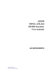
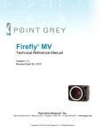
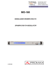
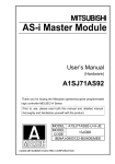
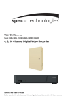
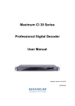
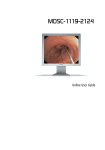
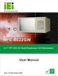
DCH-4000P Series
Professional Digital Decoder
User Manual
Table of contents
1. SAFETY............................................................................................................................................... 1
2. TECHNICAL INTRODUCTION............................................................................................................ 2
2.1 Features......................................................................................................................................... 2
2.2 Factory Options ............................................................................................................................. 2
3. INSTALLATION.................................................................................................................................... 3
3.1 Inspection and Test........................................................................................................................ 3
3.2 Functional Self Test ....................................................................................................................... 4
3.3 Mounting ........................................................................................................................................ 4
4. FRONT PANEL.................................................................................................................................... 4
4.1 Front Panel List.............................................................................................................................. 4
4.2 Indicator LEDs ............................................................................................................................... 4
4.3 Liquid Crystal Display .................................................................................................................... 5
4.4 Keypad........................................................................................................................................... 5
4.5 Common Interface ......................................................................................................................... 5
5. REAR PANEL ...................................................................................................................................... 6
5.1 Power Supply................................................................................................................................. 6
5.2 Output Connectors......................................................................................................................... 6
5.3 ASI Input Connector....................................................................................................................... 7
5.4 RS-232 Interface............................................................................................................................ 7
5.5 Ethernet Interface .......................................................................................................................... 7
5.6 TS/IP Interface (Factory Optional) ................................................................................................. 7
6. INSTALLATION.................................................................................................................................... 7
6.1 Main Menu ..................................................................................................................................... 7
6.2 System Menu................................................................................................................................. 8
6.2.1 Local Setup ............................................................................................................................. 8
6.2.2 Setting up the Trap IP Address ............................................................................................... 8
6.2.3 Editing the Unit Name ............................................................................................................. 9
6.2.4 Checking the Properties ......................................................................................................... 9
6.2.5 Recover Factory Default Settings ........................................................................................... 9
6.2.6 Setting Machine Type ............................................................................................................. 9
7. Manual for DCH-4000P-30S /-30T/-30C/-30S2 .................................................................................. 9
7.1 Menu Structure for DCH-4000P-30S /-30T/-30C/-30S2 ................................................................ 9
7.2 Setting Inputs for DCH-4000P-30S /-30T/-30C/-30S2 .................................................................11
7.2.1 Checking Status of Inputs ......................................................................................................11
7.2.2 Setting the Tuner Parameters................................................................................................11
7.3 Setting Outputs for DCH-4000P-30S /-30T/-30C/-30S2.............................................................. 13
7.3.1 Checking Status of Outputs .................................................................................................. 13
7.3.2 Setting Common Interface .................................................................................................... 14
7.3.3 Setting the Parameters of Decoder ...................................................................................... 14
7.3.4. Setting the ASI1 Output ....................................................................................................... 15
7.3.5. Setting the ASI2/SDI Output ................................................................................................ 15
7.3.6. Setting the Mux/Filter ........................................................................................................... 15
8. Manual for DCH-4000P-41S /-41T/-41C/-41S2 ................................................................................ 15
8.1 Menu Structure for DCH-4000P-41S /-41T/-41C/-41S2 .............................................................. 15
8.2 Setting Inputs for DCH-4000P-41S /-41T/-41C/-41S2 ................................................................ 18
8.2.1 Checking Status of Inputs ..................................................................................................... 18
8.2.2 Setting the Tuner Parameters............................................................................................... 18
8.2.3 Setting the Ethernet Connector ............................................................................................ 18
8.3 Setting Outputs for DCH-4000P-41S /-41T/-41C/-41S2.............................................................. 19
9. Manual for DCH-4000P-42S /-42T/-42C/-42S2 ................................................................................ 19
9.1 Menu Structure for DCH-4000P-42S /-42T/-42C/-42S2 .............................................................. 19
9.2 Setting Inputs for DCH-4000P-42S /-42T/-42C/-42S2 ................................................................ 21
9.3 Setting Outputs for DCH-4000P-42S /-42T/-42C/-42S2.............................................................. 22
9.3.1 Setting the Ethernet TS over IP output ................................................................................. 23
9.3.2 Other output settings for DCH-4000P-42S /-42T/-42C/-42S2 .............................................. 23
10. REMOTE MONITORING AND CONTROL...................................................................................... 23
10.1 Install HDMS to a PC................................................................................................................. 23
10.2 Connect to HDMS...................................................................................................................... 23
10.3 Login to HDMS .......................................................................................................................... 24
10.4 Add DCH-4000P-xx to HMDS.................................................................................................... 24
10.5 DCH-4000P-xx in HDMS ........................................................................................................... 24
10.6 Other Settings............................................................................................................................ 25
11. FAQ.................................................................................................................................................. 25
12. Appendix.......................................................................................................................................... 25
12.1 Specification............................................................................................................................... 25
DCH-4000P-xx series Receivers
1. SAFETY
Please read this chapter before installation and use of the device
This equipment is provided with a protective earthing ground incorporated in the power cord.
The main plug shall only be inserted in a socket outlet provided with a protective earth contact.
Any interruption of the protective conductor, inside or outside the device, is likely to make the
device dangerous.
The device described in this manual is designed to be used by properly-trained personnel
only. Adjustment, maintenance and repair of the device shall be carried out by qualified
personnel.
No operator serviceable parts inside. Refer servicing to qualified personnel. To prevent
electrical shock, do not remove covers.
For the correct and safe use of the device, it is essential that both operating and servicing
personnel follow generally accepted safety procedures in addition to the safety precautions
specified in this manual.
Whenever it is likely that safety protection is impaired, the device must be made in-operative
and secured against unintended operation. The appropriate servicing authority must be
informed. For example, safety is likely to be impaired if the device fails to perform the
intended measurements or shows visible damage.
WARNINGS
z
Do not use the equipment in moisture environment surroundings.
Avoid direct contact with water.
z
Never place the equipment in direct sunlight.
z
The outside of the equipment may be cleaned using a lightly dampened cloth. Do not use
any cleaning liquids containing alcohol, methylated spirit or ammonia etc.
z
For continued protection against fire hazard, replace line fused only with same type.
WWW.PBI-CHINA.COM
-1-
DCH-4000P-xx series Receivers
2. TECHNICAL INTRODUCTION
DCH-4000P-xx is a professional IRD with a variety of input (including DVB over ASI, IP,
QPSK, QAM, COFDM and DS3) and output (CVBS, SDI, ASI, DS3 and IP) combinations. An
appropriate IP port equipped as an option supports DVB over IP applications. LAN control
and monitoring are achieved with TCP/IP, SNMP and HDMS*.
(*Headend Devices Management System, a remote management software)
2.1 Features
z
Fully complies with MPEG-2, MP@ML and DVB-S/-T/-C standards
z
IP input or output with UDP/RTP (optional)
z
Multicast and Unicast on IP
z
Supports PAL, NTSC or SECAM
z
Supports various Conditional Access systems
z
SDI video output with digital audio embedded
z
Two sets of independent ASI outputs
z
Automatic PMT update
z
Compatible with Multiple De-encrypt CI modules
z
DS3 I/O for TS (optional)
z
Switchable audio sound track
z
Teletext VBI, EBU subtitle and DVB subtitle
z
Upgradeable through LAN
z
Easy-to-use LCD menu
2.2 Factory Options
WWW.PBI-CHINA.COM
-2-
DCH-4000P-xx series Receivers
Figure 2.1 Factory Option list of DCH-4000P series
3. INSTALLATION
Warning:
This equipment is provided with a protective earthing ground incorporated in the power cord.
The main plug shall only be inserted in a socket outlet provided with a protective earth contact.
Any interruption of the protective conductor, inside or outside the instrument, is likely to make
the instrument dangerous. The type of main plugged shipped with each instrument depends
on the country of application.
Caution:
Do not connect AC power until you have verified that the line voltage is correct and the proper
fuses are installed. The equipment requires a power source of either 50/60 Hz at 110V or
50/60 Hz at 240V. The voltage ranges for these nominal voltage values are shown in the
table:
POWER REQUIREMENT
Input voltage
90-260 Vrms auto select
Frequency
47 to 63 Hz
Power
50 VA max. / 30 VA typical.
Current
110 V/0.27A or 240 V/0.125A typical
Caution:
Be sure the supply voltage is within the specified range.
Checking the fuses:
The recognized recommended fuses are size 5 by 20 mm, rate T 2.0A, 250 V (UL and IEC
approved).
The line fuse is housed in a small container besides the power connector on the rear panel.
To check the fuse, insert the tip of a screwdriver in the slot at the middle of the container and
pry gently to extend the fuse where there is a little tap and pull out the fuse gently. The fuse is
attached to the line module and cannot be removed.
3.1 Inspection and Test
Check if the devise has any visible damage. If everything seems all right, power can be
applied to the device. The main socket and fuse are located at the rear panel of the device.
When the device is turned on, verify that the display shows the following message:
DCH-4000P
(factory default unit-name)
IP: 168.192.1.21
(factory default IP Address)
If no message is shown in the display or there is not light in the display, the device is
WWW.PBI-CHINA.COM
-3-
DCH-4000P-xx series Receivers
defective and has to be returned for servicing.
3.2 Functional Self Test
No specific functional self test is needed.
The device has been factory tested according to recognized test procedures and is ready for
operation.
3.3 Mounting
The environment should be relatively dust free, free of excessive vibration and the ambient
temperature between 0 ℃ to 40 ℃. Relative humidity of 20% to 80% (non-condensed) is
recommended.
Air intake for cooling is achieved via holes at the side of the device and the fans inside. The
air flow should not be obstructed. Therefore, the device has to be placed on a flat surface,
leaving some space at the sides of the device.
When in operation, the internal temperature should not exceed the limit of 70 ℃.
4. FRONT PANEL
4.1 Front Panel List
Figure 4.1 Front Panel of DCH-4000P-xx Series Receiver
4.2 Indicator LEDs
There are 3 LED-indicators:
-POWER: the status of the power supply
green: the power is turned on
off
: the power is turned off
-TUNER LOCK: the status of the tuner
green: The incoming QPSK is locked by the tuner.
off
: there is no QPSK input signal or the signal is unlocked
-ALARM: the status of input signal source, which includes IP input, QPSK signal input and
DVB-ASI TS input.
WWW.PBI-CHINA.COM
-4-
DCH-4000P-xx series Receivers
4.3 Liquid Crystal Display
The 2 x 20 character Liquid Crystal Display (LCD) shows all the required information about
the selected parameters.
The top row of the LCD shows the selected parameter. The bottom row indicates the present
values and how these can be adjusted.
The parameters are grouped in three menus:
-the Inputs, which gives the full operation on inputs parameters
-the Outputs, with the full operation control functions on outputs parameters
-the Systems, gives the general device management parameters and informs about the
device working status
4.4 Keypad
Figure 4.2 Keypad of DCH-4000P-xx series
The 6 keys on the front panel allow you to navigate in the information given on the LCD and
to change parameters, when the device operates under local control.
The <ENTER>-key is used to enter the main menu or a sub-menu. When you stand on the
preferred menu, <ENTER> is used to active the parameter on the bottom line and allows you
to change the value. It also finishes the input of new alphanumeric values and confirms the
changes.
The <
>-and<
>-keys are used to select between the main menus or sub-menus. When
you stand on the preferred menu and the parameter is active, they are also used to change
the numerical values. Selecting a digit with the < >-and <
>-keys.
The <EXIT>-key, is used to exit a menu without any action.
4.5 Common Interface
There are two Common Interface slots. You can insert up to two different CAM modules for
descrambling.
WWW.PBI-CHINA.COM
-5-
DCH-4000P-xx series Receivers
5. REAR PANEL
Figure 3.2 Rear Panel of DCH-4000P-xx Series
B1
TS/IP Input/Output interface
B2
XRL L interface
B3
XRL R interface
B4
RGB/YUV interface (G/Y)
B5
RGB/YUV interface (B/U)
B6
RGB/YUV interface (R/Y)
B7
CVBS2 Output interface
B8, B18
ASI2/SDI output interface
B9, B19
ASI1 output interface
B17
ASI input interface
B10
RS-232 interface
B11
Tuner Loop Out interface
B12
Tuner In interface
B13
Power socket, AC 90~260V
B14
CVBS1 Output interface
B15, B16
L-Audio-R interface
B20
Ethernet interface for remote management system
B21
Grounding
5.1 Power Supply
The power cord is inserted to an IEC main socket at the side of the device.
Check that the power cord is suitable for the country where the device will be used.
A standard power cord with a European DIN 49441 two pin main plug is delivered together
with the device.
The line fuses are housed in a small container at the side of the power supply connector.
5.2 Output Connectors
The ASI interface B9), B19) and ASI2 interface B8), B18) are two pairs of independent ASI
output. Both use female BNC connectors, with 75 Ohm impedance. The ASI interface B18)
and B19) are used as a redundant output of B8) and B9) out.
WWW.PBI-CHINA.COM
-6-
DCH-4000P-xx series Receivers
Note: the B8), B18) interface could be configured as SDI with Audio embedded. Please refer
to Chapter 7.3.5.
5.3 ASI Input Connector
The ASI input B17) is a 75 ohm female BNC connector.
5.4 RS-232 Interface
This interface is a 9-pins female sub-D connector. The RS-232 interface is only used for
factory software upgrade and configuration, so you are not allowed to connect any cable to
the RS-232 connector, as that could damage the device.
5.5 Ethernet Interface
An RJ-45 connector B20) provides a remote control interface.
5.6 TS/IP Interface (Factory Optional)
An RJ-45 connector B1) provides a streaming stream over IP input or output.
6. INSTALLATION
The device allows you to configure, control and monitor through the Keypad and front panel
display when a remote control system is not used.
6.1 Main Menu
Turn on the device and wait for 8 to 10 seconds, while the device will complete self inspection
and configuration. The top row of the LCD shows the name of the device. The local IP address is
displayed on the bottom row of the LCD.
Note: the local IP address can be changed in the System Menu.
Use the <ENTER>-key to enter on the Main Menu. The <
between the three main menus.
WWW.PBI-CHINA.COM
-7-
>-and<
>-keys are used to choose
DCH-4000P-xx series Receivers
Figure 6.1 Main Menu
6.2 System Menu
The system menu provides information about the general functions, the surroundings
equipment and the hardware used.
Figure 6.2 System Menu
6.2.1 Local Setup
Each DCH-4000P-xx has an IP address, a network sub mask and a gateway. These must be
set to an appropriate value for the network over which the unit can be accessed by the
remote control system such as the HDMS.
-IP Address: The IP address for the unit.
-Network Mask: The network mask for the subnet to which the unit is connected.
-Gateway: The gateway for the network to which this unit is connected.
6.2.2 Setting up the Trap IP Address
The DCH-4000P-xx provides a Monitor Center IP address. You can set this to be the same IP
address of the Monitor Center, which is typically a PC in order to allow the device to send
messages to the monitor center. If the DCH-4000P-xx is connected with the HDMS remote
management system, the Trap IP address is typically set to be the IP address of the PC on
which the HDMS has been installed.
WWW.PBI-CHINA.COM
-8-
DCH-4000P-xx series Receivers
6.2.3 Editing the Unit Name
The DCH-4000P-xx allows you to edit the unit name which is displayed on the front panel
LCD. The unit name should not be longer than 20 characters in ASCII format.
6.2.4 Checking the Properties
You are allowed to check the properties information of the device.
- MAC address: Factory-set MAC address which is guaranteed to be unique. You cannot
configure this address.
- FW Version: the version of the FPGA software.
- SW Version: the version of the main software.
6.2.5 Recover Factory Default Settings
All the user configurable parameters will be set to the factory default settings, including IP
address and the unit name. Note that the unit will not be connected with the HDMS remote
management system until the IP is properly configured.
6.2.6 Setting Machine Type
This setting is reserved for factory-setting, and you are not allowed to access this menu.
7. Manual for DCH-4000P-30S /-30T/-30C/-30S2
7.1 Menu Structure for DCH-4000P-30S /-30T/-30C/-30S2
Note: only the Inputs menu differs from DCH-4000P-30S /-30T/-30C/-30S2 models.
WWW.PBI-CHINA.COM
-9-
DCH-4000P-xx series Receivers
Figure 7.1 Full Menu Structure for DCH-4000P-30S
WWW.PBI-CHINA.COM
- 10 -
DCH-4000P-xx series Receivers
Figure 7.2 Inputs Menu Structure for DCH-4000P-30T
Figure 7.3 Inputs Menu Structure for DCH-4000P-30C
Figure 7.4 Inputs Menu Structure for DCH-4000P-30S2
7.2 Setting Inputs for DCH-4000P-30S /-30T/-30C/-30S2
Under Input Menu, you can monitor and configure the parameters of the Tuner.
7.2.1 Checking Status of Inputs
- ASI Input: locked or unlock indicate the status of the ASI input.
- Tuner Input: when the QPSK/QAM/COFDM signal is locked by the tuner, the bit rate is
displayed on the bottom row of LCD.
7.2.2 Setting the Tuner Parameters
To receive the QPSK/QAM/COFDM signal, these parameters below must be set to
appropriate values for the receiving antenna over which the device can receive the signal.
WWW.PBI-CHINA.COM
- 11 -
DCH-4000P-xx series Receivers
For QPSK Tuner:
- LNB Local Oscillator (L.O.) Freq: enter the frequency of the LNB in MHz.
- Satellite Freq: edit the satellite down link frequency in MHz. The IF frequency will be
calculated automatically.
- Symbol Rate: enter the QPSK symbol rate.
- LNB Voltage: select the correct LNB voltage output of the F-connector: Off, 13 V, 18 V. <A>
- LNB 22KHz: activate the LNB 22 kHz control signal to the LNB: On or Off. <B>
- Note: please contact the local satellite operator for the satellite frequency and symbol rate.
<A> Normally, 13V switches the LNB to receive Vertical/Left hand polarization
while 18V receive Horizontal/Right hand.
<B> Normally, 22KHz control signal switches the LNB to receive high band if any.
For QAM Tuner:
- Constellation: enter the modulation mode of the QAM signal.
- Frequency: enter the frequency of the QAM signal in MHz.
- Symbol Rate: edit the symbol rate to the proper value in KBaud.
For COFDM Tuner:
- Frequency: enter the proper frequency of the COFDM signal in MHz.
For DVB-S2 Tuner:
- LNB Local Oscillator (L.O.) Freq: enter the frequency of LNB in MHz.
- Satellite Freq: edit the satellite down link frequency in MHz. The IF frequency will be
calculated automatically.
- Symbol Rate: enter the QPSK/8PSK symbol rate.
- LNB Voltage: select the correct LNB voltage output of the F-connector: Off, 13 V, 18 V. <A>
- LNB 22KHz: activate the LNB 22 kHz control signal to the LNB: On or Off. <B>
- Note: please contact the local satellite operator for the satellite frequency and symbol rate.
<A> Normally, 13V switches the LNB to receive Vertical/Left hand polarization
while 18V receive Horizontal/Right hand.
<B> Normally, 22KHz control signal switches the LNB to receive high band if any.
- Demodulation Mode: select the DVB-S or DVB-S2 demodulation mode.
- Operation Mode: select the appropriate operation mode in the menu. There are QPSK 1/2,
2/3, 3/4, 4/5, 5/6, 8/9, 9/10 and 8PSK 2/3, 3/4, 3/5, 5/6, 8/9, 9/10 to
choose among.
- Pilot: select Off or On according to the actual signal.
- Roll-Off Factor: you can choose 0.2, 0.25 or 0.35.
WWW.PBI-CHINA.COM
- 12 -
DCH-4000P-xx series Receivers
7.3 Setting Outputs for DCH-4000P-30S /-30T/-30C/-30S2
Figure 7.5 Outputs Menu Structure for DCH-4000P-30S /-30T/-30C/-30S2
7.3.1 Checking Status of Outputs
There are 2 displays on the LCD for monitoring the status of the decoder and the common
interface.
- Decoder: OK or Alarms indicates the status of the decoder. You can use the <ENTER>-key
to check detailed information in the submenu of the Decoder.
- CI: You can check the information of the CAM Modules in Slot1 and Slot2.
WWW.PBI-CHINA.COM
- 13 -
DCH-4000P-xx series Receivers
7.3.2 Setting Common Interface
There are 2 submenus: CI Source and Setup which allow you to set or select the parameters
of the CI.
- CI Source: select Tuner or ASI input to set the signal source of descrambling.
- Setup: press the <
> or <
>-key to select the program which is expected to be
descrambled, then press the <ENTER>-key to choose Slot1, or Slot2, or Bypass.
Press the <EXIT>-key after configuration, and the following message will be shown
on the LCD: “Confirm Changed? ENTER=YES, EXIT=NO”. If you want to keep the
changes, press the <ENTER>-key.
0-xxxxx displays the program name, which signal source is ASI.
1-xxxxx displays the program name, which signal source is TUNER.
2-xxxxx displays the program name, which signal source is TS/IP (this is invalid for
30 -10S/-11T/-12C/-13S2 series).
3-xxxxx factory occupied.
7.3.3 Setting the Parameters of Decoder
You can configure the parameters of Video and Audio of the program decoded by decoder.
- Program: Press the <
> or <
>-key to select the program which is expected to be
decoded. Press the < >-and <
>-key to choose channel from 0 to 3, then
press the <ENTER>-key to confirm.
0-xxxxx displays the program name, which comes from ASI input.
1-xxxxx displays the program name, which comes from TUNER input.
2-xxxxx displays the program name, which comes from TS/IP input (this is
invalid for 30 -10S/-11T/-12C/-13S2 series).
3-xxxxx displays the program name which comes from the CI.
- Video: You can configure the video parameters of programs in this submenu. Press the
<ENTER>-key to confirm and press the <EXIT>-key to cancel.
Video Standard: you can select Auto or SECAM or NTSC or PAL for the
composite video output.
Screen: select the screen mode: 4:3 Full, 16:9 Full or 4:3 Letterbox.
DVB Subtitle Lang: select the language of DVB Subtitle.
EBU Subtitle Lang: select the language of EBU Subtitle.
Subtitle Priority: configure the priority of Subtitle; choose whether DVB or EBU
should be first.
- Audio: You can configure the audio settings in the submenu.
Audio Level: use the <
><
>< ><
>-keys to modify the audio level within
this range: 0~99.
Audio Mode: select Stereo, Left, Right or Mono for soundtracks.
Audio Language: select the language of the audio.
WWW.PBI-CHINA.COM
- 14 -
DCH-4000P-xx series Receivers
7.3.4. Setting the ASI1 Output
User can configure the settings of ASI1 in this menu.
- ASI Source: select the signal source of ASI output: CI De-encrypted, TUNER, ASI Input or
Mux-TS.
- ASI Package Length: you can configure the package length of ASI output as 188 bytes or
select Bypass.
Note: the Mux-TS is only valid when the Mux or Filter is enabled and turned on. The Mux-TS
indicates not only the after-multiplexed TS when Mux is enabled, but also the
after-filtered TS when the filter is enabled.
7.3.5. Setting the ASI2/SDI Output
The ASI2/SDI port is user-configured as ASI output or SDI output.
If the port is configured as ASI2, the configuration method is the same as ASI. (Please refer to
the paragraph 7.3.4.)
If the port is configured as SDI, there are two parameters which need to be set: Audio PID
and Embed Audios.
- Audio PID: press the <
><
>-keys to choose the audio PID from 1~4.
- Embed Audios: there are 4 options: none, one&two, two, and one.
7.3.6. Setting the Mux/Filter
Note: the Mux / Filter are alternative.
For Mux
Mux Switch: the internal multiplexer could be switched On/Off.
Bit Rate: set the output bit rate of the multiplexed TS in Kbps.
TS ID: you can configure the TS ID to mark the multiplexed TS.
Program List: the list of programs multiplexed. Press the <ENTER>-key to select the
program which is expected to be multiplexed. A “*” will be displayed in the front
of the program name. Press the <ENTER>-key again to deselect a program.
For Filter
Filter Switch: the internal filter could be switched On/Off.
Bit Rate: set the output bit rate of the filtered TS in Kbps.
Source: select the source of the TS which is expected to be filtered.
Program List: the list of programs filtered. Press the <ENTER>-key to select the program
which is expected to be filtered away. A “*” will be displayed in the front of the
program name. Press the <ENTER>-key again to deselect a program.
8. Manual for DCH-4000P-41S /-41T/-41C/-41S2
8.1 Menu Structure for DCH-4000P-41S /-41T/-41C/-41S2
Note: the Input menu differs from DCH-4000P-41S /-41T/-41C/-41S2 models according to the
type of tuner.
WWW.PBI-CHINA.COM
- 15 -
DCH-4000P-xx series Receivers
WWW.PBI-CHINA.COM
- 16 -
DCH-4000P-xx series Receivers
Figure 8.1 Full Menu Structure for DCH-4000P-41S
Figure 8.2 Inputs Menu Structure for DCH-4000P-41T
Figure 8.3 Inputs Menu Structure for DCH-4000P-41C
WWW.PBI-CHINA.COM
- 17 -
DCH-4000P-xx series Receivers
Figure 8.4 Inputs Menu Structure for DCH-4000P-41S2
8.2 Setting Inputs for DCH-4000P-41S /-41T/-41C/-41S2
In the Input Menu, you can monitor and configure the parameters of the Tuner.
8.2.1 Checking Status of Inputs
There are 2 displays on the LCD for monitoring the status of input.
- ASI Input: locked or unlock indicates the ASI input status.
- Tuner Input: when a satellite signal is locked via the tuner, the bit rate is displayed on the
bottom row of the LCD.
- IP IN: this indicates the status of the transport stream over IP input. The bitrate is displayed
on the bottom row of the LCD, if IP input is valid.
8.2.2 Setting the Tuner Parameters
Please refer to paragraph 7.2.2.
8.2.3 Setting the Ethernet Connector
There is an Ethernet connector for receiving transport stream over IP. The Ethernet connector
has user-configurable IP address, network mask and default gateway. These must be set to
appropriate values for the network over which the transport stream over IP is received.
- Source IP Addr: Enter the IP address for streaming IP input of the unit.
- Source Network: Enter the network sub mask for the subnet to which the unit is connected
for IP streaming traffic.
- Source Gateway: Set the gateway for the network to which the unit is connected for IP
streaming traffic.
WWW.PBI-CHINA.COM
- 18 -
DCH-4000P-xx series Receivers
- Source Mac Address: factory-set MAC addresses are guaranteed to be unique. Therefore
you cannot configure the address.
- Multicast IP Addr: Enter the IP address of the multicast stream for the transport stream
over IP.
- Multicast UDP Port: Enter the UDP port number of the TS over IP stream.
- Protocol: select the protocol for multicast: UDP or RTP.
- Output Smoothing: set the quality of TS which comes from the TS/IP input.
Auto: the bit rate is variable.
Disable: the unit let the TS pass by.
Fixed Rate: the bitrate is fixed.
- TS Bit Rate: set the bit rate of the TS comes from the TS/IP input. The setting is only valid
when the output smoothing is configured as Fixed Rate.
8.3 Setting Outputs for DCH-4000P-41S /-41T/-41C/-41S2
Please refer to paragraph 7.3 for the setting method.
Note that the TS over IP input also could be configured as the source of CI, ASI, ASI2 and
Mux/Filter.
9. Manual for DCH-4000P-42S /-42T/-42C/-42S2
9.1 Menu Structure for DCH-4000P-42S /-42T/-42C/-42S2
Note: the Input menu differs from DCH-4000P-42S /-42T/-42C/-42S2 models according to the
different type of tuner.
WWW.PBI-CHINA.COM
- 19 -
DCH-4000P-xx series Receivers
WWW.PBI-CHINA.COM
- 20 -
DCH-4000P-xx series Receivers
Figure 9.1 Full Menu Structure for DCH-4000P-42S
Figure 9.2 Inputs Menu Structure for DCH-4000P-42T
Figure 9.3 Inputs Menu Structure for DCH-4000P-42C
Figure 9.4 Inputs Menu Structure for DCH-4000P-42S2
9.2 Setting Inputs for DCH-4000P-42S /-42T/-42C/-42S2
Please refer to paragraph 7.2 for the setting method.
WWW.PBI-CHINA.COM
- 21 -
DCH-4000P-xx series Receivers
9.3 Setting Outputs for DCH-4000P-42S /-42T/-42C/-42S2
Figure 9.5 Outputs Menu Structure for DCH-4000P-42S /-42T/-42C/-42S2
WWW.PBI-CHINA.COM
- 22 -
DCH-4000P-xx series Receivers
9.3.1 Setting the Ethernet TS over IP output
The Ethernet connector could also be configured as the output of the transport stream over IP.
The parameters listed below must be set to appropriate values for the network over which the
transport stream over IP is broadcasted.
- Stream IP Address: Enter the IP address for streaming IP output of the unit.
- Stream Network Mask: Enter the network sub mask for the subnet to which the unit is
connected for IP streaming traffic.
- Stream Gateway: Set the gateway for the network to which the unit is connected for IP
streaming traffic.
- Stream Mac Address: factory-set MAC addresses are guaranteed to unique. Therefore you
cannot configure the address.
- Multicast IP address: Enter the IP address of the multicast stream for the transport stream
over IP output.
- UDP Port: Enter the UDP port number of the TS over IP stream output.
- Protocol: select the protocol for multicast: UDP or RTP.
- TS Pkts Per UDP: set the number of the TS packages encapsulated in one UDP package.
The valid range goes from 1 to 7.
- Time To Live: set the number of the routers over which the TS over IP can be transmitted.
The valid range goes from 1 to 5.
- Type of Service: select the type of service. There are: Normal, Min Monetary Cost, Max
Reliability, Max Throughput or Min Delay optional.
- Source: select the source of the TS over IP streaming output. There are: ASI Input, CI
De-encrypted or TUNER.
9.3.2 Other output settings for DCH-4000P-42S /-42T/-42C/-42S2
Please refer to paragraph 7.3 for the other output setting method.
10. REMOTE MONITORING AND CONTROL
The DCH-4000P-xx series provides an Ethernet remote control interface for user remote
control or supervise one or multiple DCH-4000P-xx via the Headend Devices Management
System (HDMS).
10.1 Install HDMS to a PC
The HDMS Installation.exe file could be found on the CD-ROM which is enclosed in the
original package. Detailed information about installation can be found in the HDMS Reference
Guide.
10.2 Connect to HDMS
After installation of HDMS, you need to configure the local settings of the DCH-4000P-xx (s)
which is/are expected to connect to the remote control network. Please refer to paragraph 6.2.1.
WWW.PBI-CHINA.COM
- 23 -
DCH-4000P-xx series Receivers
10.3 Login to HDMS
To login on HDMS, a user account and password are needed. Default user account is:
administrator, password is: admin. You can create or delete new accounts. Detailed information
can be found in the HDMS Reference Guide.
10.4 Add DCH-4000P-xx to HMDS
Ensure the DCH-4000P-xx are well connected with the network over which the PC that
installed the HDMS can access the DCH-4000P-xx. Press the
icon in the top left of the
window in HDMS to and the system will search the DCH-4000P-xx automatically. The units
which are searched will be displayed in the Devices Window in HDMS.
When a new DCH-4000P-xx is added to the remote control network, you can press
to refresh the network. The new added unit will be added into the HDMS automatically. For
other methods for adding one or a group of DCH-4000P-xx, please refer to the HDMS
Reference Guide.
10.5 DCH-4000P-xx in HDMS
Double click on the device in the Devices Management window to open the console of the
DCH-4000P-xx. The HDMS provides full operation to the DCH-4000P-xx. Parameters are
grouped in three panels:
- The Input Setting, which gives the full operation on inputs parameters.
- The Output Setting, allows the full operation control functions on outputs parameters.
- The System Setting, shows the general device management parameters.
Each console has four control buttons:
- Apply: to apply the current settings for the unit which is being accessed.
- Refresh: to obtain the current settings from the unit.
- Load: to load the pre-settings files to the HDMS, and press “Apply” to apply the pre-settings
for the unit.
- Save: save the user’s settings as an .xml file.
Remark: When duplicating the configuration of one device to the other unit(s), you need to
modify the System Setting (such as IP address, gateway, Unit name, etc) manually
after loading the .xml file.
WWW.PBI-CHINA.COM
- 24 -
DCH-4000P-xx series Receivers
10.6 Other Settings
The HDMS provides also Alarms management, Devices management, and User accounts
management. It may also be necessary to modify some of the other settings to suit the
particular installation, please see the HDMS Reference Guide for details.
11. FAQ
1. Why is there nothing in the LCD?
Answer: Please check whether the power supply is connected well first. If not, insert it well
and turn on the device. If there is still nothing displayed on the LCD, then the unit may be
damaged, please contact the agent for technical support.
2. Why can the QPSK/QAM/COFDM/DVB-S2 signal not be locked?
Answer: Please ensure whether the input cable in connected well first. If not, insert it well.
If it is connected well, please check whether all the necessary parameters are set properly.
If not, please set the parameters properly. If the signal still cannot be locked, please check
whether the quality of the signal is out of the threshold of the Tuner. If not, then the device
might be damaged, please contact the agent for support.
3. Why can the ASI not be locked?
Answer: Please make sure the BNC cable is connected well and there are programs
transmitted to the unit via the BNC cable.
12. Appendix
12.1 Specification
QPSK Demodulation & FEC Parameters
Input Frequency Range
C & Ku Band, 950~2150 MHz
Input Level
-25 dBm ~ -65 dBm
Input Impedance
75 Ω F type
Symbol Rate
2~45 Mb/s (SCPC or MCPC)
Rolling Off Factory
0.20 or 0.35
Punctured Rates
1/2, 2/3, 3/4, 5/6, 6/7, 7/8
Reeds Salomon Decoding
204, 188, T = 8 & I=12
DVB-C QAM Demodulation
Connector
IEC, Female (7/8 MHz) or F Female (6 MHz) Input
Input Symbol Rate Range
1~7 Mbs (PAL), 1~6 Mbps (NTSC)
Demodulation
16/32/64/128/256 QAM
Tuner Bandwidth
6 MHz or 7 MHz or 8 MHz factory optional
FEC Decoder
1/2, 2/3, 3/4, 5/6, 7/8; K=7
WWW.PBI-CHINA.COM
- 25 -
DCH-4000P-xx series Receivers
Frequency Range
50~860 MHz
Digital Signal Input Level
-15~15 dBmV
Input Impedance
75 Ω F-type
DVB-T COFDM Demodulation
Connector
IEC, Female (7/8 MHz) or F Female (6 MHz) Input
1 IF Loop through
Yes
Frequency Range
470-862 MHz, 174-230 MHz
Input Symbol Rate Range
4.98~31.67 Mbit/s (8 MHz bandwidth)
Constellation
QPSK, 16-QAM, 64-QAM
Tuner Bandwidth
8 MHz
Digital Signal Input Level
-20 to -75 dBmV
Input Impedance
75 Ω unbalanced
FFT mode
2K/8K
Guard Interval
1/4, 1/8, 1/16, 1/32, off
FEC Code Rate
1/2, 2/3, 3/4, 5/6 and 7/8
DS3 Input
Input Impedance
75 Ω
Connector
BNC
Maximum Input Code Rate
44.736 Mbit/s
Format
Unframed Framing according to G.804/G.752 (DS3)
DS3 Loop Through Output
Impedance
75 Ω
Maximum Output Code Rate
44.736 Mbit/s
Connector
BNC
Format
Unframed Framing according to G.804/G.752 (DS3)
TS over IP Output
Connector
100 base-T RJ45
Output Bit Rate
70 Mbits/s Max.
UDP/RTP
Multicast or Unicast
Multicast Control Protocol
IGMPV2
I/O Interface on back panel
LNB I/O
1×Input, 1×loop through output
RS-232
1×9-pin D-sub male
RJ45
1×Ethernet control port, 1×TS over IP output
(factory optional)
ASI input
1
ASI output
2×Redundant output
SDI output
1 (optional)
RGB output
1×RCA
CVBS output
1×RCA, 1×BNC
WWW.PBI-CHINA.COM
- 26 -
DCH-4000P-xx series Receivers
Audio XRL Balance Output
1
General
Operating Temperature
0-45 ℃
Storage Temperature
-20~70 ℃
Humidity
<85%
Power Supply
AC 90V~260V
Dimensions
483 mm×255 mm×44 mm
Approximately Net Weight
5 kg
WWW.PBI-CHINA.COM
- 27 -
50Hz/60Hz
DCH-4000P-xx series Receivers
Pro Broadband Inc.
Tel: +86 (0)10 6263 8833
Fax: +86 (0)10 6263 7776
Website: www.pbi-china.com
E-Mail: [email protected]
This document and the information contained in it is the property of Pro Broadband Inc. and
may be the subject of patents pending and granted. It must not be used for commercial
purposes nor copied, disclosed, reproduced, stored in a retrieval system or transmitted in any
form or by any means (electronic, mechanical, photocopying, recording or otherwise),
whether in whole or in part, without Pro Broadband Inc.‘s prior written agreement.
© 2007 Pro Broadband Inc. All rights reserved.
WWW.PBI-CHINA.COM
- 28 -