1
AIM PCB
User’s & Reference Guide
Version 3.0
Part Number 00713-00530, Rev. A
August 1996
5RVH 2UFKDUG :D\ 6DQ -RVH &$ 86$ 3KRQH )D[ 2WWR+DKQ6WUDVVH 'RUWPXQG *HUPDQ\ 3KRQH )D[ 9RLH OD &DUGRQ 3DODLVHDX )UDQFH 3KRQH )D[ $]D 1DNDKDUD 0LWVX\D&KR 7R\RKDVKL $LFKL.HQ -DSDQ )D[ The information contained herein is the property of Adept Technology, Inc., and shall not
be reproduced in whole or in part without prior written approval of Adept Technology,
Inc. The information herein is subject to change without notice and should not be construed as a commitment by Adept Technology, Inc. This manual is periodically reviewed
and revised.
Adept Technology, Inc., assumes no responsibility for any errors or omissions in this document. Critical evaluation of this manual by the user is welcomed. Your comments assist
us in preparation of future documentation. A form is provided at the back of the book for
submitting your comments.
Copyright © 1992, 1996 by Adept Technology, Inc. All rights reserved.
The Adept logo is a registered trademark of Adept Technology, Inc.
Adept, AdeptOne, AdeptOne-MV, AdeptThree, AdeptThree-MV, PackOne, PackOne-MV,
HyperDrive, Adept 550, Adept 550 CleanRoom, Adept 1850, Adept 1850XP,
A-Series, S-Series, Adept MC, Adept CC, Adept IC, Adept OC, Adept MV,
AdeptVision, AIM, VisionWare, AdeptMotion, MotionWare, PalletWare,
AdeptNet, AdeptFTP, AdeptNFS, AdeptTCP/IP, AdeptForce, AdeptModules,
and V+ are trademarks of Adept Technology, Inc.
Any trademarks from other companies used in this publication
are the property of those respective companies.
Printed in the United States of America
Table Of Contents
Read Me First! . . . . . . . . . . . . . . . . . . . . . . . . . . . . . . . . . . . . . . . . . . . . . . . . . . . . . . . . . . . . . . . . . . . . . . . . . . . . . . . . . . . . . . . . . . . . . . . . 1
What Is AIM PCB? . . . . . . . . . . . . . . . . . . . . . . . . . . . . . . . . . . . . . . . . . . . . . . . . . . . . . . . . . . . . . . . . . . . . .
What Do I Already Need to Know? . . . . . . . . . . . . . . . . . . . . . . . . . . . . . . . . . . . . . . . . . . . . . .
What Should I Have Already Done? . . . . . . . . . . . . . . . . . . . . . . . . . . . . . . . . . . . . . . . . . . . . .
Software Installation and Start-up . . . . . . . . . . . . . . . . . . . . . . . . . . . . . . . . . . . . . . . . . . . . . . . .
Do I Have to Read All the Manuals? . . . . . . . . . . . . . . . . . . . . . . . . . . . . . . . . . . . . . . . . . . . . .
How Do I Use AIM PCB? . . . . . . . . . . . . . . . . . . . . . . . . . . . . . . . . . . . . . . . . . . . . . . . . . . . . . . . . . . . .
How Can I Get Help? . . . . . . . . . . . . . . . . . . . . . . . . . . . . . . . . . . . . . . . . . . . . . . . . . . . . . . . . . . . . . . . .
Service Calls . . . . . . . . . . . . . . . . . . . . . . . . . . . . . . . . . . . . . . . . . . . . . . . . . . . . . . . . . . . . . . . . . . .
Training Information . . . . . . . . . . . . . . . . . . . . . . . . . . . . . . . . . . . . . . . . . . . . . . . . . . . . . . .
Application Information . . . . . . . . . . . . . . . . . . . . . . . . . . . . . . . . . . . . . . . . . . . . . . . . . . .
International Customer Assistance . . . . . . . . . . . . . . . . . . . . . . . . . . . . . . . . . . . . .
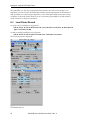
Chapter 1.
1.1
1.2
1.3
Chapter 2.
2.1
Parts and Part Types
1
1
1
2
2
3
4
4
4
4
4
...................................................................
5
What Are Parts and Part Types? . . . . . . . . . . . . . . . . . . . . . . . . . . . . . . . . . . . . . . . . . . . . . . . . . . . . . .
Part Records . . . . . . . . . . . . . . . . . . . . . . . . . . . . . . . . . . . . . . . . . . . . . . . . . . . . . . . . . . . . . . . . . . . . . . . . . . . . . . . .
Part Menu Page Options . . . . . . . . . . . . . . . . . . . . . . . . . . . . . . . . . . . . . . . . . . . . . . . . . . . . . . . . . . . .
Part Type Records . . . . . . . . . . . . . . . . . . . . . . . . . . . . . . . . . . . . . . . . . . . . . . . . . . . . . . . . . . . . . . . . . . . . . . . .
Part Type Menu Page Options . . . . . . . . . . . . . . . . . . . . . . . . . . . . . . . . . . . . . . . . . . . . . . . . . . . .
5
6
6
7
7
Feeders
.....................................................................................
9
2.3
What Are Feeders? . . . . . . . . . . . . . . . . . . . . . . . . . . . . . . . . . . . . . . . . . . . . . . . . . . . . . . . . . . . . . . . . . . . . . . . . 9
Feeder Menu Page Options . . . . . . . . . . . . . . . . . . . . . . . . . . . . . . . . . . . . . . . . . . . . . . . . . . . . . . 11
Using Pallet Feeders . . . . . . . . . . . . . . . . . . . . . . . . . . . . . . . . . . . . . . . . . . . . . . . . . . . . . . . . . . . . . . . . . . . . 12
Pallet Parameters Menu Page Options . . . . . . . . . . . . . . . . . . . . . . . . . . . . . . . . . . . . . . . . 12
How Rows and Columns Are Determined . . . . . . . . . . . . . . . . . . . . . . . . . . . . . . . . . . 13
Feeder Control Signals . . . . . . . . . . . . . . . . . . . . . . . . . . . . . . . . . . . . . . . . . . . . . . . . . . . . . . . . . . . . . . . . . 13
Specifying Feeder Control Signals . . . . . . . . . . . . . . . . . . . . . . . . . . . . . . . . . . . . . . . . . . . . . . 13
Feeder Enabled Signal . . . . . . . . . . . . . . . . . . . . . . . . . . . . . . . . . . . . . . . . . . . . . . . . . . . . . . . . . . . . . 13
Feeder Input Signal . . . . . . . . . . . . . . . . . . . . . . . . . . . . . . . . . . . . . . . . . . . . . . . . . . . . . . . . . . . . . . . . . 14
Feeder Output Signals . . . . . . . . . . . . . . . . . . . . . . . . . . . . . . . . . . . . . . . . . . . . . . . . . . . . . . . . . . . . . 14
Reenabling a Feeder . . . . . . . . . . . . . . . . . . . . . . . . . . . . . . . . . . . . . . . . . . . . . . . . . . . . . . . . . . . . . . . . 14
Chapter 3.
Tool Records . . . . . . . . . . . . . . . . . . . . . . . . . . . . . . . . . . . . . . . . . . . . . . . . . . . . . . . . . . . . . . . . . . . . . . . . . . . . 15
2.2
3.1
3.2
3.3
What Are Tool Records? . . . . . . . . . . . . . . . . . . . . . . . . . . . . . . . . . . . . . . . . . . . . . . . . . . . . . . . . . . . . . .
The Tool Menu Page . . . . . . . . . . . . . . . . . . . . . . . . . . . . . . . . . . . . . . . . . . . . . . . . . . . . . . . . . . . . . . . . . . .
Tool Menu Page Options . . . . . . . . . . . . . . . . . . . . . . . . . . . . . . . . . . . . . . . . . . . . . . . . . . . . . . . . . .
Tool Control Signals . . . . . . . . . . . . . . . . . . . . . . . . . . . . . . . . . . . . . . . . . . . . . . . . . . . . . . . . . . . . . . . . . . . .
AIM PCB User’s & Reference Guide, Rev. A
15
16
16
17
iii
Table of Contents
3.4
Chapter 4.
4.1
4.2
4.3
Chapter 5.
5.1
5.2
5.3
Chapter 6.
6.1
6.2
6.3
6.4
6.5
Chapter 7.
7.1
7.2
7.3
7.4
7.5
Specifying Tool Control Signals . . . . . . . . . . . . . . . . . . . . . . . . . . . . . . . . . . . . . . . . . . . . . . . . .
Part present . . . . . . . . . . . . . . . . . . . . . . . . . . . . . . . . . . . . . . . . . . . . . . . . . . . . . . . . . . . . . . . . . .
Open gripper . . . . . . . . . . . . . . . . . . . . . . . . . . . . . . . . . . . . . . . . . . . . . . . . . . . . . . . . . . . . . . . .
Close gripper . . . . . . . . . . . . . . . . . . . . . . . . . . . . . . . . . . . . . . . . . . . . . . . . . . . . . . . . . . . . . . . .
Raise gripper . . . . . . . . . . . . . . . . . . . . . . . . . . . . . . . . . . . . . . . . . . . . . . . . . . . . . . . . . . . . . . . .
Lower gripper . . . . . . . . . . . . . . . . . . . . . . . . . . . . . . . . . . . . . . . . . . . . . . . . . . . . . . . . . . . . . .
Displaying the Tool Controls Values . . . . . . . . . . . . . . . . . . . . . . . . . . . . . . . . . . . . . . . . . . . . . .
Using the Transfer Statement
17
17
17
17
17
17
18
.....................................................
19
Statement Syntax and Arguments . . . . . . . . . . . . . . . . . . . . . . . . . . . . . . . . . . . . . . . . . . . . . . . . . .
Sequence of Operations . . . . . . . . . . . . . . . . . . . . . . . . . . . . . . . . . . . . . . . . . . . . . . . . . . . . . . . . . . .
How TRANSFER Uses the Databases . . . . . . . . . . . . . . . . . . . . . . . . . . . . . . . . . . . . . . . . . . . . . . .
Things to Remember . . . . . . . . . . . . . . . . . . . . . . . . . . . . . . . . . . . . . . . . . . . . . . . . . . . . . . . . . . . . . . . . . . .
19
19
20
21
Transferring Parts Using Vision . . . . . . . . . . . . . . . . . . . . . . . . . . . . . . . . . . . . . . . . . . . . . . . . . . 23
Statement Syntax and Arguments . . . . . . . . . . . . . . . . . . . . . . . . . . . . . . . . . . . . . . . . . . . . . . . . . .
Sequence of Operations . . . . . . . . . . . . . . . . . . . . . . . . . . . . . . . . . . . . . . . . . . . . . . . . . . . . . . . . . . .
Required Records for TRANSFER.FP . . . . . . . . . . . . . . . . . . . . . . . . . . . . . . . . . . . . . . . . . . . . . .
Optional Records for TRANSFER.FP . . . . . . . . . . . . . . . . . . . . . . . . . . . . . . . . . . . . . . . . . . . . . . . .
Vision Refinement for the Gripped Part . . . . . . . . . . . . . . . . . . . . . . . . . . . . . . . . . . . . . .
Vision Frame for the Insert Location . . . . . . . . . . . . . . . . . . . . . . . . . . . . . . . . . . . . . . . . . . .
Additional Considerations . . . . . . . . . . . . . . . . . . . . . . . . . . . . . . . . . . . . . . . . . . . . . . . . . . . . . . .
24
24
25
25
25
27
28
..........................................................
33
Introduction . . . . . . . . . . . . . . . . . . . . . . . . . . . . . . . . . . . . . . . . . . . . . . . . . . . . . . . . . . . . . . . . . . . . . . . . . . . . . .
Lead Finder Vision Tool . . . . . . . . . . . . . . . . . . . . . . . . . . . . . . . . . . . . . . . . . . . . . . . . . . . . . . . . . . . . . . .
Lead Finder Record . . . . . . . . . . . . . . . . . . . . . . . . . . . . . . . . . . . . . . . . . . . . . . . . . . . . . . . . . . . . . . . . . . . . .
Lead Finder Record Options . . . . . . . . . . . . . . . . . . . . . . . . . . . . . . . . . . . . . . . . . . . . . . . . . . . . .
Frame Finder Tool . . . . . . . . . . . . . . . . . . . . . . . . . . . . . . . . . . . . . . . . . . . . . . . . . . . . . . . . . . . . . . . . . . . . . .
Frame Finder Record . . . . . . . . . . . . . . . . . . . . . . . . . . . . . . . . . . . . . . . . . . . . . . . . . . . . . . . . . . . . . . . . . . .
Frame Finder Tool Options . . . . . . . . . . . . . . . . . . . . . . . . . . . . . . . . . . . . . . . . . . . . . . . . . . . . . . .
33
33
34
35
36
37
37
Special PCB Vision Tools
Customizing Overview . . . . . . . . . . . . . . . . . . . . . . . . . . . . . . . . . . . . . . . . . . . . . . . . . . . . . . . . . . . . . . 41
Overview . . . . . . . . . . . . . . . . . . . . . . . . . . . . . . . . . . . . . . . . . . . . . . . . . . . . . . . . . . . . . . . . . . . . . . . . . . . . . . . . . .
Prerequisite Background Information . . . . . . . . . . . . . . . . . . . . . . . . . . . . . . . . . . . . . . . . . . . . .
Databases . . . . . . . . . . . . . . . . . . . . . . . . . . . . . . . . . . . . . . . . . . . . . . . . . . . . . . . . . . . . . . . . . . . . . . . . . . . . . . . . . .
Overview of the AIM PCB Module . . . . . . . . . . . . . . . . . . . . . . . . . . . . . . . . . . . . . . . . . . . . . . . . . .
Database Summary . . . . . . . . . . . . . . . . . . . . . . . . . . . . . . . . . . . . . . . . . . . . . . . . . . . . . . . . . . . . . . . . .
Menu Summary . . . . . . . . . . . . . . . . . . . . . . . . . . . . . . . . . . . . . . . . . . . . . . . . . . . . . . . . . . . . . . . . . . . . .
Runtime Routines . . . . . . . . . . . . . . . . . . . . . . . . . . . . . . . . . . . . . . . . . . . . . . . . . . . . . . . . . . . . . . . . . . . . . . .
41
41
42
42
43
44
44
Chapter 8.
Databases . . . . . . . . . . . . . . . . . . . . . . . . . . . . . . . . . . . . . . . . . . . . . . . . . . . . . . . . . . . . . . . . . . . . . . . . . . . . . . . . 47
8.1
8.2
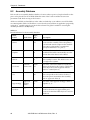
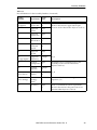
8.3
Identification Numbers . . . . . . . . . . . . . . . . . . . . . . . . . . . . . . . . . . . . . . . . . . . . . . . . . . . . . . . . . . . . . . . . 47
Assembly Database . . . . . . . . . . . . . . . . . . . . . . . . . . . . . . . . . . . . . . . . . . . . . . . . . . . . . . . . . . . . . . . . . . . . . 48
Feeder Database . . . . . . . . . . . . . . . . . . . . . . . . . . . . . . . . . . . . . . . . . . . . . . . . . . . . . . . . . . . . . . . . . . . . . . . . . 51
iv
AIM PCB User’s & Reference Guide, Rev. A
Table of Contents
8.4
8.5
8.6
Part Database . . . . . . . . . . . . . . . . . . . . . . . . . . . . . . . . . . . . . . . . . . . . . . . . . . . . . . . . . . . . . . . . . . . . . . . . . . . . . 60
Part Type Database . . . . . . . . . . . . . . . . . . . . . . . . . . . . . . . . . . . . . . . . . . . . . . . . . . . . . . . . . . . . . . . . . . . . . 61
Tool Database . . . . . . . . . . . . . . . . . . . . . . . . . . . . . . . . . . . . . . . . . . . . . . . . . . . . . . . . . . . . . . . . . . . . . . . . . . . . 64
Chapter 9.
Statements . . . . . . . . . . . . . . . . . . . . . . . . . . . . . . . . . . . . . . . . . . . . . . . . . . . . . . . . . . . . . . . . . . . . . . . . . . . . . . . 67
Chapter 10.
Primitive and Strategy Routines
.................................................
81
10.1 Acquire Primitives . . . . . . . . . . . . . . . . . . . . . . . . . . . . . . . . . . . . . . . . . . . . . . . . . . . . . . . . . . . . . . . . . . . . . .
Details of the Acquire Routine . . . . . . . . . . . . . . . . . . . . . . . . . . . . . . . . . . . . . . . . . . . . . . . . . .
Standard Part-Acquisition Strategy Routine . . . . . . . . . . . . . . . . . . . . . . . . . . . . . . . . .
Part-Acquisition Strategy Sequence . . . . . . . . . . . . . . . . . . . . . . . . . . . . . . . . . . . . . . . . . . . .
Acquire Strategy Routine . . . . . . . . . . . . . . . . . . . . . . . . . . . . . . . . . . . . . . . . . . . . . . . . . . . . . . . . .
Pallet Part-Acquisition Strategy Routine . . . . . . . . . . . . . . . . . . . . . . . . . . . . . . . . . . . . .
10.2 Insertion Primitives . . . . . . . . . . . . . . . . . . . . . . . . . . . . . . . . . . . . . . . . . . . . . . . . . . . . . . . . . . . . . . . . . . . . .
Details of the Insertion Routine . . . . . . . . . . . . . . . . . . . . . . . . . . . . . . . . . . . . . . . . . . . . . . . . .
Standard Part-Insertion Strategy Routine . . . . . . . . . . . . . . . . . . . . . . . . . . . . . . . . . . . .
Part-Insertion Strategy Sequence . . . . . . . . . . . . . . . . . . . . . . . . . . . . . . . . . . . . . . . . . . . . . . .
Insert Strategy Routine . . . . . . . . . . . . . . . . . . . . . . . . . . . . . . . . . . . . . . . . . . . . . . . . . . . . . . . . . . . .
10.3 Reject Primitives . . . . . . . . . . . . . . . . . . . . . . . . . . . . . . . . . . . . . . . . . . . . . . . . . . . . . . . . . . . . . . . . . . . . . . . . .
Details of the Reject Routine . . . . . . . . . . . . . . . . . . . . . . . . . . . . . . . . . . . . . . . . . . . . . . . . . . . . .
Standard Part-Rejection Strategy Routine . . . . . . . . . . . . . . . . . . . . . . . . . . . . . . . . . . . .
Part-Rejection Strategy Sequence . . . . . . . . . . . . . . . . . . . . . . . . . . . . . . . . . . . . . . . . . . . . . . .
Reject Strategy Routine . . . . . . . . . . . . . . . . . . . . . . . . . . . . . . . . . . . . . . . . . . . . . . . . . . . . . . . . . . . .
81
81
83
83
85
86
87
87
88
89
90
91
91
91
92
93
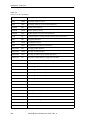
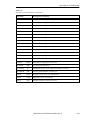
Appendix A. Disk Files . . . . . . . . . . . . . . . . . . . . . . . . . . . . . . . . . . . . . . . . . . . . . . . . . . . . . . . . . . . . . . . . . . . . . . . . . . . . . . . 107
Index . . . . . . . . . . . . . . . . . . . . . . . . . . . . . . . . . . . . . . . . . . . . . . . . . . . . . . . . . . . . . . . . . . . . . . . . . . . . . . . . . . . . . . . . . . . . . . . . . . . . . . . . . 111
Index of Programs and Statements
.................................................................
113
Index of Global Variables . . . . . . . . . . . . . . . . . . . . . . . . . . . . . . . . . . . . . . . . . . . . . . . . . . . . . . . . . . . . . . . . . . . . . . . . . . . . . 115
AIM PCB User’s & Reference Guide, Rev. A
v
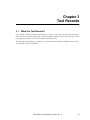
Read Me First!
What Is AIM PCB?
AIM PCB (Printed Circuit Board) is designed for the Adept AIM system and is an add-on module to
MotionWare. AIM PCB allows you to create sophisticated robot workcell implementations without
using low-level programming. AIM PCB is designed primarily for printed circuit board
applications, but can be used for any tasks that involve placing multiple parts onto a single
assembly.
What Do I Already Need to Know?
You should be familiar with your robot and the capabilities of the robot. In particular, you should
know:
• How to power up the controller.
• How to power up and perform start-up calibration of the robot.
• How to power up and adjust any other devices in the workcell.
• The safety requirements of your robot and any other devices that operate in the workcell.
When run carelessly or by inexperienced operators, robots and other motion devices can
severely injure personnel and cause equipment damage.
• Basic operation and use of the optional Manual Control Pendant (if you will be using the
MCP).
• How to use MotionWare.
What Should I Have Already Done?
The hardware that AIM PCB will be controlling should already be installed and tested. If you are
using any of the following hardware, it should be installed:
• The robot and any of the following options you may be using:
• Fifth axis
• Force sensing module
• The controller (see the controller user’s guide) and any of the following options:
• Digital I/O (see the controller user’s guide)
• Cameras and strobes (see the MotionWare User’s Guide)
• Cell equipment, including:
• Part feeders
• Conveyors
• Connections between the cell equipment and the digital I/O system
• Safety devices needed to prevent injuries during workcell operation
AIM PCB User’s & Reference Guide, Rev. A
1
Read Me First!
Software Installation and Start-up
The MotionWare User’s Guide covers installing the software on your hard drive (a hard drive is
required to run AIM). To load and execute the software, follow the procedure described in the
MotionWare User’s Guide. Substitute the commands load lpcb and comm lpcb for load lmow and
comm lmow, respectively.
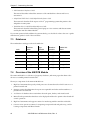
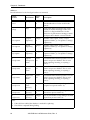
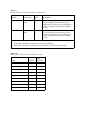
Do I Have to Read All the Manuals?
AIM PCB comes with a complete set of reference material that allows you not only to use AIM PCB,
but to customize AIM PCB at the programming (V +) level and write your own vision and robot
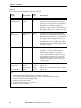
programming applications. The manuals you should read are listed in Table 1. The manuals you
can ignore (unless you are customizing AIM) are listed in Table 2.
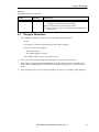
Table 1
Manuals You Should Read or Review
Manual
Material Covered
MotionWare User’s
Guide
How to use MotionWare.
AIM PCB User’s &
Reference Guide
How to use the AIM PCB software.
Robot user’s guide
Basic capabilities of your robot, as well as how to perform
the start-up procedures.
Controller user’s guide
Basics of using the controller. If you are using digital I/O,
pay particular attention to the requirements for initializing
and installing the digital I/O hardware.
Instructions for Adept
Utility Programs
Instructions for running the different Adept utility
programs. Depending on which options you use, you may
have to run different Adept utility programs. Keep the
manual handy for instructions on any utility programs you
may have to run.
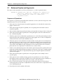
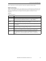
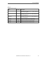
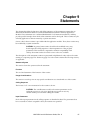
Table 2
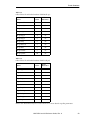
Manuals Used for Custom Programming
2
Manual
Material Covered
AIM reference manuals
These reference manuals cover the AIM database structures
and the routines used to drive the AIM system. There will be
a manual or section of a manual for the base AIM system and
each AIM module you have. If you are going to use AIM PCB
as delivered, you can ignore this material.
V+ Reference Guide
This set of reference manuals covers the operating system
and language in which all V+ and AIM programs are written.
Unless you are writing custom V+ or AIM code, you can
ignore this material.
AdeptVision Reference
Guide
(Vision only) This reference manual is a companion to the V+
Reference Guide. It details the vision enhancements to V+.
AIM PCB User’s & Reference Guide, Rev. A
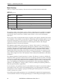
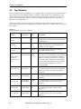
How Do I Use AIM PCB?
Table 2
Manuals Used for Custom Programming (Continued)
Manual
Material Covered
AdeptVision VME User’s
Guide
(Vision only) This manual contains the “how to” material
for Adept’s vision system. Unless you are programming
custom vision applications, you can ignore this manual. A
quick review of the manual will give you an idea of how the
vision system works
VisionWare User’s Guide
(Vision only) This manual covers the stand-alone vision
inspection module for AIM. If you are using the vision
capability of AIM PCB, you will find a review of this manual
useful.
AIM CAD Data
Translator User’s Guide
(CAD data translator only) This manual covers using the
CAD data translator to automatically create database
records from CAD data.
How Do I Use AIM PCB?
The AIM PCB implementations you will be creating involve picking up parts from a feeder location
and placing them at a given location. Basic AIM PCB operations require you to complete the
following actions:
1. Create an assembly. An assembly is the “thing” your robot system will actually build.
Creating an assembly involves specifying the locations at which parts will be placed.
2. Define the parts that will be placed on the assembly. Parts are the objects you actually pick up
and place on an assembly. Every part has an associated part type that defines how the part is
to be picked up and placed. Chapter 1 covers creating parts and part types.
3. Define the feeders that will supply the parts. A “feeder” is simply a location at which to pick
up a part. Every part requires an associated feeder to let the robot know where to pick up the
parts and what to do when the feeder is empty. Chapter 2 covers creating feeders.
In addition to the required actions, AIM PCB allows you to take several optional actions to control
the robot more effectively and accurately. These actions are:
1. Create “paths” or safe corridors along which the robot can move without damaging any
equipment in the workcell or other parts on the assembly. A path is a series of locations.
Once the robot enters a path, it should be able to move from one location in the path to
another without causing any damage. See the MotionWare User’s Guide.
2. Create reference frames. If assemblies will not always be in the same location in the workcell,
reference frames simplify updating of the locations on an assembly. If you have the vision
option, reference frames can be automatically updated using vision data. See the MotionWare
User’s Guide.
If your system has the vision option, the vision system can:
1. Update an assembly reference frame (Chapter 6).
2. Update the true location and orientation of parts picked up by the robot (Chapter 5).
3. Update the actual locations where the robot is to place parts (Chapter 5).
4. Inspect parts before they are placed (Chapter 6).
AIM PCB User’s & Reference Guide, Rev. A
3
Read Me First!
How Can I Get Help?
Service Calls
Adept Technology maintains a fully staffed Customer Service Center at its headquarters in San
Jose, California.
When calling an Adept Customer Service Center, select the appropriate phone number from the
following list:
(800) 232-3378 from anywhere in the continental United States
(49) 231 / 75 89 40 from within Europe
(408) 434-5000 from outside the continental US or Europe
When calling Customer Service, please have the serial number of the controller and the system
software version. The controller’s serial number is on the right side of the controller. The system
software version is available by entering the command id at the system prompt.
Training Information
For information regarding Adept Training Courses in the USA, please call (408) 434-5024.
Application Information
For applications assistance with Adept products, please call (800) 232-3378.
International Customer Assistance
Europe
For information on training, service, or applications, Adept has a Customer Service Center in
Dortmund, Germany. The phone number is (49) 0231 / 75 89 40.
Outside Europe or USA
For information on training or applications, call (408) 434-5000. Adept’s FAX number is (408)
433-9462.
4
AIM PCB User’s & Reference Guide, Rev. A
Chapter 1
Parts and Part Types
1.1
What Are Parts and Part Types?
Each part acquired and placed onto an assembly must have a part record and an associated part
type record. The part record gives a name to the part, indicates which feeders the part can be
acquired from, and specifies which part type the part is. The part type record specifies how to
acquire, insert, and reject the part, as well as any tool transformation (described in the MotionWare
User’s Guide) used when the part is acquired.
Separating parts and part types avoids the redundancy of specifying the acquisition and insertion
parameters for parts that are physically identical. For example, you might have 15 different
resistors that are physically identical but vary in resistance value. All these resistors would be
acquired and inserted in the same manner.
In this example, you would create 15 part records, to identify the different resistors and the feeders
that supply the resistors, but only one part type record that specifies how to acquire and insert the
15 different resistors. Parts that are physically unique will have a part type record for each part
record.
AIM PCB User’s & Reference Guide, Rev. A
5
Chapter 1 - Parts and Part Types
1.2
Part Records
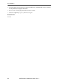
To create a new part record, perform:
Edit
➡ Part ➡ Edit ➡ New Record
To edit an existing part, perform:
Edit
➡ Part ➡ Seek ➡ Index ➡ double-click “part record name”
➋
➌
➊
➍
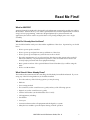
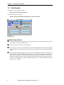
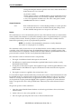
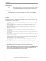
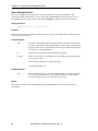
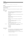
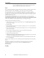
Figure 1-1
Part Menu Page
Part Menu Page Options
➊
➋
➌
➍
6
Shows the name of the current part record, the number of this record in the database, and the
total number of records in the database.
Shows the date this record was last modified.
Enter a part type to be associated with this part. Double-clicking this data box when it is empty
displays a pick list of defined part types that can be selected. Part types are detailed in the next
section.
Enter the feeders that supply this type of part. Double-clicking these data boxes when they are
empty displays a pick list of defined feeders that can be selected. All feeders specified must
use the same acquisition strategy (specified in the part type record). Feeders are detailed in
Chapter 2. Each part requires at least one feeder. If the first defined feeder is empty or inactive,
the robot will attempt to access the next defined feeder, and so on until all defined feeders are
either inactive or empty.
AIM PCB User’s & Reference Guide, Rev. A
Part Type Records
1.3
Part Type Records
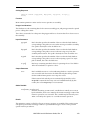
To create a new part record, perform:
Edit
➡ Part Type ➡ Edit ➡ New Record
To edit an existing part, perform:
Edit
➡ Part Type ➡ Seek ➡ Index ➡ double-click “part type record name”
The following screen is displayed:
:
➋
➌
➊
➍
➎
➏
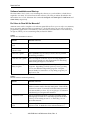
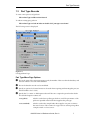
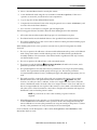
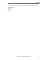
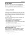
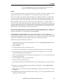
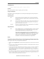
Figure 1-2
Part Type Menu Page
Part Type Menu Page Options
➊
➋
➌
➍
Shows the name of the current part type record, the number of this record in the database, and
the total number of records in the database.
Shows the date this record was last modified.
Specify an optional tool transformation to be used when acquiring and inserting this part (see
the MotionWare User’s Guide).
Specify the V+ routine or AIM sequence that will be run to acquire the part from the feeder.
The standard acquire routines are:
rn.ac.pallet( )
which is used when a pallet type feeder is used. The parameters of the
pallet are specified in the feeder that supplies this part type.
rn.ac.standard( )
which is used with a simple feeder that supplies one part at a time to
the same location. This routine also supports force sensing using either
a simple switch or a force sensor.
AIM PCB User’s & Reference Guide, Rev. A
7
Chapter 1 - Parts and Part Types
➎
Specify the V+ routine or AIM sequence that will be run to insert the part in the assembly. The
standard insertion routine is:
rn.in.standard( )
➏
8
which opens the gripper when the location is reached. This routine also
supports force sensing using either a simple switch or a force sensor.
Specify the V+ routine or AIM sequence that will be run to discard the part if it cannot be
inserted. The standard reject routine is rn.rj.standard( ). This routine moves the robot onto a
reject path and dumps the part at the first exit location on that path. See the MotionWare User’s
Guide for details on paths.
AIM PCB User’s & Reference Guide, Rev. A
Chapter 2
Feeders
2.1
What Are Feeders?
Feeders identify the locations where parts will be acquired.
Every part requires at least one feeder from which the part is acquired. An acquire strategy is
specified in the part type record associated with the part this feeder is supplying. This strategy
must agree with the actual type of feeder. For example, if the feeder is a pallet feeder, the acquire
strategy rn.ac.pallet( ) must be specified in the part type record.
AIM PCB User’s & Reference Guide, Rev. A
9
Chapter 2 - Feeders
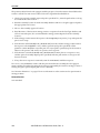
To create a new feeder, perform:
Edit
➡ Feeder ➡ Edit ➡ New Record
To edit an existing feeder, perform:
Edit
➡ Feeder ➡ Seek ➡ Index ➡ double-click “feeder record name”
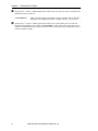
The following screen is displayed:
➋
➌
➊
➎
➍
➏
➐
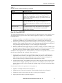
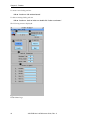
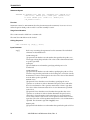
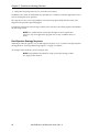
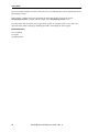
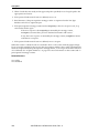
Figure 2-1
Feeder Menu Page
10
AIM PCB User’s & Reference Guide, Rev. A
What Are Feeders?
Feeder Menu Page Options
➊
➋
➌
➍
Enter a name for this feeder. The name can be changed, but part records that reference this
feeder will not be able to find the feeder unless the name change is also made in the part
record. The numbers indicate the number of this record and the total number of records in the
database.
Shows the date this record was last modified.
Shows the name of the robot device that will access this feeder.
Choose Transit to create a location the robot will move through on the way to the feeder.
This location is used when the robot must approach a feeder from a specific side or at a critical
angle.
Choose Feeder to create or edit the location at which the robot will acquire a part from this
feeder. In addition to the standard location parameters and approach and depart heights, the
feeder location has two additional variables, pickup offset X and Y. These variables behave like
approach heights, only the offset is in the X, Y plane rather than along the Z-axis. If an X, Y
offset is specified the robot will:
a. move to the approach height offset by the specified amount (if an approach has been
defined)
b. move to the offset location
c. move to the feeder location
d. depart from the feeder location.
➎
If the feeder is a pallet, choose Pallet to specify the dimensions of the pallet (see section 2.2).
NOTE: As delivered by Adept, User parameters are not used.
➏
➐
If a gripper with a “part present” sensor is used and a signal for the sensor has been
configured, Retry count specifies the maximum number of attempts that should be made to
acquire a part. Maximum time specifies the total time that should be spent trying to acquire a
part. These two parameters are used with the acquire strategy routine rn.ac.standard( ). Cycle
time specifies the time (in seconds) required by a feeder to present a new part after one is
acquired. AIM PCB will not attempt another access to this feeder until Cycle time seconds have
passed (used when there is no hardware part-ready signal).
Indicates the status of the digital I/O signals. When the button and the signal name are
dimmed, no signal has been defined. If a question mark appears in place of the button, the
signal defined is not the right type or is not properly configured. A button with a gray center
indicates that the signal is off; a button with a green center indicates that the signal is on.
Double-click on the signal name box to select an existing signal name or define a new signal
name for these controls. See the controller user’s guide for details on the physical installation
and configuration of digital I/O. See section 2.3 for details on using these specific signals.
AIM PCB User’s & Reference Guide, Rev. A
11
Chapter 2 - Feeders
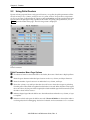
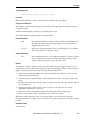
2.2
Using Pallet Feeders
If parts are being acquired from evenly spaced locations on a pallet, the pallet parameters tell the
robot how many rows, columns, and layers are on a pallet, and how far apart those components
are. If you are using a pallet feeder, the acquire routine rn.ac.pallet( ) must be specified in the part
type record for the part types being acquired at this feeder. To specify pallet parameters, choose
Pallet from the feeder menu page. The following screen is displayed:
➊
➋
➌
➍
➎
➏
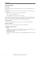
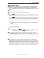
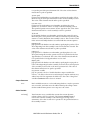
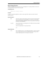
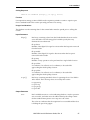
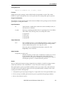
Figure 2-2
Pallet Parameters
Pallet Parameters Menu Page Options
➊
➋
➌
➍
➎
➏
12
If a reference frame has been declared for the feeder, the name of the frame is displayed here.
Enter the space between individual part locations in the row, column, and layer directions.
Enter the number of part locations in an individual row, column, and layer.
Shows the column, row, and layer that the robot will access when the next part is picked up
from this pallet. These fields are updated as the feeder is accessed. When all index values equal
the count values, the last part will be acquired, the feeder enabled signal will be turned off, and
the index values will be reset to 1.
Indicate a digital signal that should be set to the indicated state when the row, column, or layer
is complete.
Indicate in which order parts should be removed. If Freeze all indices is selected, the index is
not changed (useful for debugging). See below for details on what constitutes a row or column.
AIM PCB User’s & Reference Guide, Rev. A
Feeder Control Signals
How Rows and Columns Are Determined
Pallet rows are considered to be parallel to the feeder frame X-axis. Columns are parallel to the
feeder frame Y-axis. Layers are parallel to the feeder frame Z-axis. If the world coordinate system
is used for the feeder, the pallet will have to be lined up exactly with the axes of the world
coordinate system. Since this could be difficult to set up, pallet feeders normally use calculated
reference frames. Reference frames are described in the MotionWare User’s Guide. The strategy for
using a pallet feeder is:
1. Create a reference frame based on three locations on the pallet.
2. Declare the feeder location to be relative to this reference frame.
3. Teach the row 1, column 1, layer 1 location as the location of the feeder.
When the robot accesses the pallet feeder, it will start at row 1, column 1, layer 1 and (if row,
column, layer is specified) add the value specified in Row: Spacing to each successive access until
the number of accesses specified in Row: Count have been made. The robot will then return to the
original row offset and add the value specified in Column: Spacing for the next access. When the
current layer is completed, the robot will return to row 1, column 1, and add the value specified in
Layer: Spacing for the next access. When column count, row count, and layer count have reached
their specified values, the feeder will be disabled and the feeder alarm signal will be set. See the
MotionWare User’s Guide and the MotionWare Reference Guide for more information on pallets.
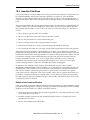
2.3
Feeder Control Signals
The feeder control signals are digital I/O signals that are used to indicate the status of a part
feeder. Before these signals can be used:
• The hardware that sets the signal or receives the signal must be installed.
• The required digital I/O modules must be installed in the controller (see the controller user’s
guide).
• The individual signal numbers must be entered into the feeder record (see below).
Specifying Feeder Control Signals
To enter feeder control signal numbers, display the feeder menu page (see Figure 2-1). You can
enter a signal number or variable database record for each feeder control signal.
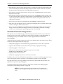
Feeder Enabled Signal
The feeder enabled signal lets AIM PCB know that a feeder is available for use. If an input signal is
not installed, a software signal (from 2001 to 2512) must be specified. If a soft signal is used to
enable or disable a feeder, select Enable: and specify the soft signal. (If this signal is left blank, AIM
PCB will assume the feeder has been deactivated and will not attempt to access it.)
AIM PCB User’s & Reference Guide, Rev. A
13
Chapter 2 - Feeders
Feeder Input Signal
Digital input senses the state of the input signal circuit. If a switch is off (circuit is open), the digital
input signal is considered off. The feeder input signal is:
Ready
This signal indicates that a part is ready. If there is no part ready sensor for this
feeder, leave the signal data box blank and AIM PCB will assume a part is ready
whenever the feeder is enabled. If an open (off) signal from a feeder sensor
indicates the part is ready, enter a negative signal number and the part ready
signal will be properly interpreted.
Feeder Output Signals
Digital output signals act as switches for user-supplied current applied to equipment in the
workcell. The feeder control output signals are:
Alarm
This signal will be set when a feeder becomes empty or the robot fails to acquire a part
from the feeder. If no signal is entered, the alarm signal is not activated.
User1
This signal can be used in custom strategy routines or sequences.
User2
This signal can be used in custom strategy routines or sequences.
User3
This signal can be used in custom strategy routines or sequences.
Reenabling a Feeder
Once a feeder has been refilled, to reenable the feeder, perform:
I/O
➡ Feeder Controls
The feeder control page will be displayed. If the wrong feeder record is displayed, perform:
Index
➡ double click on desired feeder
When the correct feeder record is displayed, press the enabled push button. The center of the push
button should turn green to indicate the feeder is enabled.
14
AIM PCB User’s & Reference Guide, Rev. A
Chapter 3
Tool Records
3.1
What Are Tool Records?
A tool record contains information pertaining to a tool for a robot. This information includes the
name of the robot (motion device), the tool transformation (offset from the end of the robot to the
tool grip point), and tool controls (I/O signals and delay times).
The information entered into each field of a tool record is stored in the Tool database. See section
8.6 for details on the Tool database.
AIM PCB User’s & Reference Guide, Rev. A
15
Chapter 3 - Tool Records
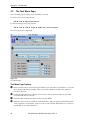
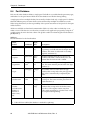
3.2
The Tool Menu Page
The Tool menu page is used to create and edit tool records.
To create a new tool record, perform:
Edit
➡ Tool ➡ Edit ➡ New Record
To edit an existing tool record, perform:
Edit
➡ Tool ➡ Seek ➡ Index ➡ double-click “tool record name”
The following screen is displayed:
➊
➋
➌
➍
➎
➏
➐
Figure 3-1
Tool Menu Page
Tool Menu Page Options
➊
➋
➌
➍
16
Enter a name for the tool record. The total number of records in the Tool database (1 of 1, in the
above figure) indicates the number of this record in the database and the total number of
records for this tool.
Double click this data box to display a list of motion devices and select the one you want
associated with this Tool record.
Shows the date and time that this record was last modified.
Enter the values for the tool offset (tool transformation). (When a sequence statement that has
a tool argument is executed, the value of tool #1 is used.) See the MotionWare User’s Guide for
more details on tool transformations.
AIM PCB User’s & Reference Guide, Rev. A
Tool Control Signals
➎
➏
➐
3.3
Choose a Set button to use the values in item ➍ as the current tool.
Specify the digital I/O signal number or variable name for each tool control signal. (These
signals do not appear in MotionWare.) See section 3.3 for details.
Specify the delay time (in seconds) that the robot will wait after the corresponding tool control
signal is activated.
Tool Control Signals
The tool control signals are digital I/O signals that are used to control the operation of the robot
grippers. See the MotionWare User’s Guide for additional information on using digital I/O.
Before these signals can be used:
• The hardware that sets the signal or receives the signal must be installed.
• The required digital I/O modules must be installed in the controller (see the controller user’s
guide).
• The individual signal numbers must be entered into the tool record (see below).
Specifying Tool Control Signals
To enter tool control signal numbers or variables, display the Tool record page (see Figure 3-1).
You can enter a signal number or variable database record for each tool control signal.
Part present
The part present input signal lets AIM PCB know that a part is held in the robot gripper. This
digital signal or variable should have the value zero if no part present sensor is connected.
Open gripper
The open gripper output signal opens the robot gripper when the signal is set to TRUE. This signal
is controlled as the complement of the close gripper signal. This digital signal or variable should
have the value zero if no open gripper signal is connected.
Close gripper
The close gripper output signal closes the robot gripper when the signal is set to TRUE. This signal
is controlled as the complement of the open gripper signal.This digital signal or variable should
have the value zero if no close gripper signal is connected.
Raise gripper
The raise gripper output signal raises the robot gripper when the signal is set to TRUE. This signal
is controlled as the complement of the lower gripper signal. This digital signal or variable should
have the value zero if no raise gripper signal is connected.
Lower gripper
The raise gripper output signal raises the robot gripper when the signal is set to TRUE. This signal
is controlled as the complement of the raise gripper signal. This digital signal or variable should
have the value zero if no lower gripper signal is connected.
AIM PCB User’s & Reference Guide, Rev. A
17
Chapter 3 - Tool Records
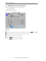
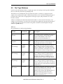
3.4
Displaying the Tool Controls Values
To display the signal values for the tool controls, perform:
I/O
➡ Tool Controls
The following screen is displayed:
➋
➊
➌
➍
Figure 3-2
Tool Controls
➊
➋
➌
➍
The name of the current tool record. To view a different record, choose Index (see item ➍).
Displays the motion device associated with the current tool record.
Displays the values of the tool control signals.
Choose Index to display a list of tool records.
Choose Done to exit the Tool Controls display.
18
AIM PCB User’s & Reference Guide, Rev. A
Chapter 4
Using the Transfer Statement
TRANSFER is the basic AIM PCB statement. It performs a pick-and-place operation, acquiring a part
from a feeder and inserting it into an assembly. In addition, it can follow optional paths while
moving to the feeder, moving to the assembly, rejecting a bad part, and departing from the
assembly.
4.1
Statement Syntax and Arguments
The syntax for this statement is as follows, where braces ({...}) enclose optional clauses:
TRANSFER {APPROACH path} PART part {ALONG path} TO assembly
{DEPART path} {USING tool} {REJECT path}
Sequence of Operations
The sequence of operations performed by this statement is as follows (the relevant portion of the
statement syntax is shown for each step):
1. If the optional tool transformation is specified, apply that tool to describe the current robot
gripper. ({USING tool})
2. If the optional approach path is specified, move along that path to the feeder locations.
({APPROACH path})
3. Select a feeder and pick up a part. (PART part)
4. If the optional transit path is specified, move along that path to the assembly location.
({ALONG path})
5. Place the part onto the assembly. (TO assembly)
6. If the placement fails and the optional reject path is specified, follow the reject path and discard the bad part. ({REJECT path}) (If the insertion fails and the optional reject path is not
specified, AIM PCB pauses the sequence and sends an error message to the operator.)
7. If the optional depart path is specified, depart from the assembly area along that path.
({DEPART path})
AIM PCB User’s & Reference Guide, Rev. A
19
Chapter 4 - Using the Transfer Statement
4.2
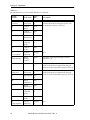
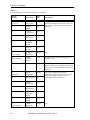
How TRANSFER Uses the Databases
Table 4-1 shows the statement clause, the databases accessed by that clause, and the information
retrieved from each database.
Table 4-1
TRANSFER Statement
Clause
Database
Information
APPROACH path
Path
Path to use moving from current robot location to the part
feeder.
Entry point nearest the current robot location.
Exit point nearest the location being moved to.
Transit locations between the entry and exit points.
PART part
Part Type
Feeder
The part being acquired.
The part type associated with this part.
The possible feeders.
The part acquisition, insertion, and reject strategies.
A tool transformation to use (overridden if “USING tool” is
defined).
Transit location to move through on way to feeder.
The feeder location, including:
Approach and depart heights
Arm configuration
Reference frame
Motion parameters for all moves
X/Y offsets for approaching the Pallet feeder parameters.
Feeder digital I/O signals.
Retry limits for grippers with “part present” sensors.
Minimum cycle time for feeder access.
ALONG path
Path
Path to use moving from the feeder to the assembly
location.
Entry point nearest the current robot location.
Exit point nearest the location being moved to.
Transit locations between the entry and exit points.
TO assembly
Assembly
The part insertion location, including:
Approach and depart heights
Arm configuration
Reference frame
Motion parameters for all moves
DEPART path
Path
Path to use when leaving the insertion location.
Entry point nearest the current robot location.
Exit point nearest the location being moved to.
Transit locations between the entry and exit points.
USING tool
Tool
A tool transformation to use for all robot motions.
20
AIM PCB User’s & Reference Guide, Rev. A
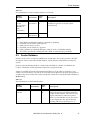
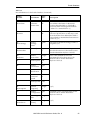
Things to Remember
Table 4-1
TRANSFER Statement (Continued)
Clause
Database
Information
REJECT path
Path
Path to use moving from the assembly location when
rejecting a part that failed to be inserted.
Entry point nearest the current robot location.
First exit point after entry point (the part will be dumped at
this location).
4.3
Things to Remember
1. The minimum information required to execute a TRANSFER statement is:
•A part
•A part type for the part, including insert and acquire strategies
•A feeder for the part, including:
The feeder location
An enabled digital I/O signal
•An assembly with at least one insertion location.
2. All location data must be taught with the proper tool transformation in place.
3. If the acquire strategy routine rn.ac.pallet( ) is used, the reference frames specified for the
feeder and assembly database locations must be defined with respect to a named reference
frame.
4. Each module must have an associated assembly. You cannot use assembly global databases.
AIM PCB User’s & Reference Guide, Rev. A
21
Chapter 5
Transferring Parts
Using Vision
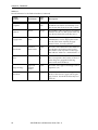
The TRANSFER.FP statement performs pick-and-place operations for PCB assembly using the
vision system to improve the placement accuracy. It acquires a part from a feede; visually inspects
the part and determines precisely how the part is being held; visually inspects the assembly
location and determines its precise location; and then places the part at that location. See
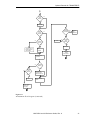
“TRANSFER.FP Flow Diagram” on page 30 for details.
The vision operations permit high-accuracy placement even when the initial part grasping
location and the final assembly placement location are known only approximately. In addition,
this statement allows optional paths to be followed while moving to the feeder, moving to the
vision inspection locations, rejecting a bad part, moving to the assembly, rejecting a part that failed
to be placed, and departing from the assembly.
AIM PCB User’s & Reference Guide, Rev. A
23
Chapter 5 - Transferring Parts Using Vision
5.1
Statement Syntax and Arguments
The syntax for this statement is as follows, where braces ({...}) enclose optional clauses:
TRANSFER.FP {APPROACH path} PART part {{APPROACH path} {REFINE vision
{AND vision}} {REJECT path}} {ALONG path} {LOCATE vision}
TO board {DEPART path} {USING tool} {REJECT path}
{OK_SIGNAL variable}
Sequence of Operations
The sequence of operations performed by this statement is as follows (the relevant portion of the
statement syntax is shown for each step):
1. If the optional tool transformation is specified, apply that tool to describe the current robot
gripper. ({USING tool})
2. If the optional approach path is specified, move along that path to the feeder locations.
({APPROACH path})
3. Select a feeder and pick up a part by executing a part acquisition strategy routine. (PART part)
4. If the optional transit path is specified, move along that path to the vision refinement location. ({{APPROACH path})
5. If the first optional vision refinement is specified, move to each of the picture taking locations,
inspect the part, and compute the part position in the gripper. Save a robot tool adjustment
value based on the vision results. ({REFINE vision}).
6. If the first optional vision refinement succeeds and the second optional vision refinement is
specified, rotate the part 180°, move to each of the picture taking locations, inspect the part,
and compute the part position. Modify the saved robot tool adjustment value based on the
vision results. This additional step compensates for any camera position errors in the X,Y
plane (but does not compensate for rotational errors). ({AND vision})
7. If either vision refinement inspection fails and the optional reject path is specified, follow the
reject path and discard the bad part and acquire a new part (loop to step 2). ({REJECT path}})
(If the optional reject path is not specified, AIM stops processing the sequence and sets the
operator alert signal.)
8. If the optional transit path is specified, move along that path to the assembly location.
({ALONG path})
9. If the optional vision assembly locating operation is specified, move to each of the picture-taking locations, inspect the assembly location and compute the precise assembly location. Adjust the robot TOOL based on the vision results. ({LOCATE vision})
10. If one or both of the optional vision part position refinement operations have been performed, apply the saved robot tool adjustment value to the robot TOOL to compensate for any
error in grasping the part.
11. Place the part onto the assembly. (TO board)
24
AIM PCB User’s & Reference Guide, Rev. A
Required Records for TRANSFER.FP
12. If the visual inspection fails or the placement fails and the optional reject path is specified, follow the reject path and discard the bad part and acquire a new part (loop to step 2). ({REJECT
path}) If the optional reject path is not specified, AIM stops processing the sequence and sends
an error message to the operator.
13. If the optional departure path is specified, depart from the assembly area along that path.
({DEPART path})
14. If the statement completes all defined arguments through the DEPART argument, the output
signal is set to TRUE. Otherwise, the output signal is set to FALSE. ({OK_SIGNAL variable})
5.2
Required Records for TRANSFER.FP
The records required by TRANSFER.FP are the same as the standard TRANSFER statement. These
records are:
• Part
• Part Type
• Feeder
• Assembly
See Chapter 4 for details on these records.
5.3
Optional Records for TRANSFER.FP
TRANSFER.FP uses five optional records. The first two records are identical to the standard
TRANSFER statement. They are:
• Path
• Tool
See Chapter 4 for details on these records.
The three additional optional records used by TRANSFER.FP are vision records. These records are
detailed in the rest of this section.
Vision Refinement for the Gripped Part
The REFINE vision and AND vision clauses of the TRANSFER.FP statement require a vision
record that returns a vision frame defining the actual location of a part in the robot gripper. The
center and orientation of this frame are used to calculate the true center of the part. If both vision
clauses are used, the results of both operations are averaged to calculate the true part center. The
offset of the true part center from the actual gripper center will be taken into account when the
robot attempts to place the part. The most commonly used vision tools that return a frame result
are:
• Blob Finder (VisionWare User’s Guide)
• Prototype Finder (VisionWare User’s Guide)
• Frame Finder (Chapter 6)
• Computed Frame (VisionWare User’s Guide)
The frame class vision tools may require additional vision records to supply the information
needed to calculate the frame. Vision record types are detailed in the VisionWare User’s Guide.
AIM PCB User’s & Reference Guide, Rev. A
25
Chapter 5 - Transferring Parts Using Vision
The camera record for the refinement operation should have the following characteristics:
• The camera used to generate the frame should be a stationary camera that the robot presents
the part to.
• The camera should have been calibrated with one of the camera calibration options (see the
VisionWare User’s Guide).
The picture record for the refinement operations should be set up as follows (see the description of
the Robot Motion Information pop-up window in the MotionWare User’s Guide):
Select ✔ Object moved by robot.
If
Vision target location is selected:
Specify a path name in the PATH name: data box. The path record controls the motion
parameters for moving to the picture-taking location. These include speed, motion type,
etc. The path record also controls the offset of the vision target with respect to the robot
gripper.
Set the path reference frame to
World (see the description of the Path Segment menu
page in the MotionWare User’s Guide). When the robot moves the gripped part in front of
the camera, it uses the location values created during camera calibration to move the
gripper in front of the camera.
Specify the path segment in the Path segment: data box (located on the Robot Motion
Information pop-up window). This is used to offset the camera from the camera location
specified during camera calibration.
If you are using a computed frame to calculate the true part center, and the tools needed to
compute the frame will not fit on a single screen, you can use multiple picture records
with different path segments to move the camera to the different locations. AIM PCB will
take care of the necessary calculations to generate the frame.
Enter values in the Placement in FOV: data boxes to offset the picture-taking location by
the specified amount. The default values (50/50) center the robot at the vision location.
This offset is in addition to any offsets defined in the path location.
Choose Here to record the current location of the object being viewed by the camera in
the specified path database record as the picture-taking location.
If
Robot location is selected:
The path segment specified in the PATH name: data box will be the location the robot
moves to when taking a picture.
Choose Here to record the current location of the robot tool tip in the specified path
database record as the picture-taking location.
If ✔ Auto-select is selected, the first vision refinement operation (REFINE vision) will use
segment 1 of the specified path, and the second refinement argument (AND vision) will use
segment 2 of the specified path. This allows you to use the same vision operation for each
argument. If you enter a value in the Path segment: data box, that segment will be used
during the refine operation.
26
AIM PCB User’s & Reference Guide, Rev. A
Optional Records for TRANSFER.FP
Vision Frame for the Insert Location
The LOCATE vision clause of TRANSFER.FP also requires a vision record returning a frame
result. This record must return the actual center of the placement location. The offset of the true
center of the placement location from the defined assembly location is taken into account when the
robot attempts to place the part. The vision tools commonly used to return a frame result are:
• Blob Finder (VisionWare User’s Guide)
• Prototype Finder (VisionWare User’s Guide)
• Frame Finder (Chapter 6)
• Computed Frame (VisionWare User’s Guide)
The camera record used to generate the vision frame should have the following characteristics:
• It should be a robot-mounted camera. The camera should have been calibrated using the
“Arm-Mounted Camera Calibration” option described in the MotionWare User’s Guide.
• The vision frame must have its Z-axis pointing away from the camera. See the “Camera
Record Options” section in the VisionWare User’s Guide for details on making this change.
• If this camera also is being used for a LOCATE.ASSEMBLY statement, load two virtual
cameras, one with the Z-axis pointing towards the camera for the LOCATE.ASSEMBLY
operation, and one with the Z-axis pointing away from the camera for the TRANSFER.FP
operation.
The picture record should be set up as follows (see the description of the Robot Motion
Information pop-up window in the MotionWare User’s Guide):
Do not select
If
Object moved by robot.
Vision target location is selected:
Specify a path name in the PATH name: data box. The path record controls the motion
parameters for moving to the picture-taking location. These include, speed, motion type,
etc. The path record also controls the offset of the vision target with respect to the
assembly location.
Set the path reference frame to
Dynamic (see the description of the Path Segment
menu page in the MotionWare User’s Guide). When the robot moves the camera over the
assembly, it uses the camera-to-robot offsets created during camera calibration to move
the camera, rather than the gripper, over the assembly location.
Specify the path segment in the Path segment: data box (located on the Robot Motion
Information pop-up window). If the path segment contains all zeros, the center of the
assembly location will be used as the vision target. Nonzero values for X and Y move the
vision target within the vision plane.
If the camera is not mounted on the final link of the robot, the values of Z and orientation
control the tool height and orientation with respect to the assembly location when the
picture is taken.
NOTE: An important use of the path is to move the quill out of the way of
the assembly (the camera-to-robot transformation does not take into
account any Z offset). Since assembly locations have a pitch of 180°, a
negative value for the Z offset must be used to keep the gripper above the
board. See “robot approach minimum” in the robot initialization database
file ROBINI.DB.
AIM PCB User’s & Reference Guide, Rev. A
27
Chapter 5 - Transferring Parts Using Vision
If you are using a computed frame to calculate the true assembly location, and the tools
needed to compute the frame will not fit on a single screen, you can use multiple picture
records with different path segments to move the camera to the different locations. AIM
PCB will take care of the necessary calculations to generate the frame.
Choose Here , and the current robot offsets from the assembly location will be recorded
in the specified path segment (during walk-thru training only).
If
Robot location is selected:
The path segment specified in the Location data box will be the location the robot moves to
when taking a picture
Choose Here to record the current robot location in the specified path segment.
If
Auto-select is selected, the (LOCATE vision) operation will use segment 1 of the
specified path. If you enter a value in the Path segment: data box, that segment will be used
as the vision target offset or the robot location.
Additional Considerations
1. A part type with at least one feeder must be defined in the Part database. Remember, the minimum information required to execute a TRANSFER statement is:
•A part
•A part type for the part, including insert and acquire strategies
•A feeder for the part, including:
The feeder location
An enabled digital I/O signal
•An assembly with at least one insertion location.
2. If your robot is using a tool transformation to acquire and place parts, teach all locations and
calibrate LOCATE vision clauses with the tool transformation in place (see the VisionWare
User’s Guide).
3. If you are using a pallet feeder, make sure the strategy routine rn.ac.pallet( ) is specified in
the part type record and the pallet parameters and proper reference frame have been
assigned in the feeder record.
28
AIM PCB User’s & Reference Guide, Rev. A
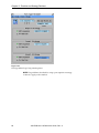
Optional Records for TRANSFER.FP
4. The values generated by the vision operations are added to any existing values of the current
TOOL to create the final placement location. When debugging the REFINE vision or
LOCATE vision clauses, observe the robot TOOL transformation before and after the refinement. If it changes drastically, either the camera calibration is incorrect or parameters on the
picture record or associated path are set up incorrectly. The current values of TOOL can be
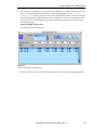
seen by performing:
Setup
➡ Display/Change Tool
The following screen is displayed:
Figure 5-1
Display/Change Tool Menu Page
5. Each module must have an associated assembly. You cannot use assembly global databases.
AIM PCB User’s & Reference Guide, Rev. A
29
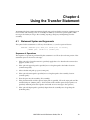
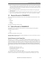
Chapter 5 - Transferring Parts Using Vision
USING
--tool-defined?
execute
TRANSFER.FP
Tool
defined in
part type
rec?
no
yes
yes
apply tool
set tool
to NULL
➀
no
picture
location is
robot loc?
yes
APPROACH
--path-defined?
move to cam cal
location offset by
path location
move to
path
location
yes
enter path
perform vision
operation
select feeder
REJECT
--path-defined?
acquire part
operation
passed?
yes
no
no
REFINE
--vision-defined?
no
➋
yes
halt
yes
AND
--vision-defined?
no
no
move to reject
location and
dump part
APPROACH
--path-defined?
➊
yes
yes
enter path
AND
--vision-processed?
no
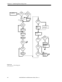
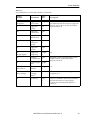
Figure 5-2
TRANSFER.FP Flow Diagram
30
AIM PCB User’s & Reference Guide, Rev. A
yes
calculate tool
correction
based on
vision data
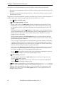
➋
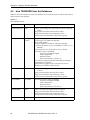
Optional Records for TRANSFER.FP
➁
ALONG
--path-defined?
no
yes
enter path
LOCATE
--vision-defined?
part
placement yes
succeeded?
no
execute
next
statement
no
yes
no
no
path
location is
robot loc?
halt
REJECT
--path-defined?
yes
yes
enter path
move to
path
location
move to cam cal
location offset by
path location
dump part
at first
exit location
perform vision
operation
➊
no
operation
passed?
yes
yes
REJECT
--path-defined?
calculate tool
correction from
defined vision ops
no
halt
Apply correction
to tool
move to reject
location and
dump part
➊
Figure 5-2
TRANSFER.FP Flow Diagram (Continued)
AIM PCB User’s & Reference Guide, Rev. A
31
Chapter 6
Special PCB Vision Tools
6.1
Introduction
The TRANSFER.FP and LOCATE.ASSEMBLY statements use vision tools to refine robot motions
based on the actual conditions of the workcell. The standard vision record types are described in
the VisionWare User’s Guide.
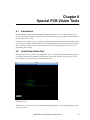
AIM PCB has two special vision tools that are used with printed circuit board assembly. The special
tools are the lead finder and the frame finder. The lead finder inspects the leads of a surface mount
device. The frame finder creates a vision reference frame for rectangular parts. These tools are
described in this chapter.
6.2
Lead Finder Vision Tool
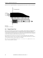
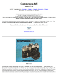
The first special PCB vision tool is the lead finder. This tool inspects the lead width and spacing of
a surface mount device and returns a line based on the average position and orientation of the
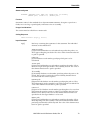
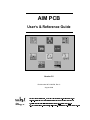
leads. Figure 6-1 shows the layout of the lead finder tool.
Figure 6-1
Lead Finder Tool
The dimensions of the tool can be set either with the drag handles or by entering absolute values
in the tool record.
AIM PCB User’s & Reference Guide, Rev. A
33
Chapter 6 - Special PCB Vision Tools
The lead finder tool will stop locating leads if the primary ruler fails to find an edge or an
individual search area fails to find leads that meet the spacing requirements. If the number of
leads specified are located and pass inspection, a line will be generated based on the average
orientation of the leads. Frame finder tools can use the lines generated by four lead finders to
create a frame for a surface mount device.
6.3
Lead Finder Record
To create a new lead finder record, perform:
Edit ➡ Vision ➡ Edit ➡ New Record
Types: Lead Finder ➡ OK
➡ enter lead finder record name ➡ Other Record
To edit an existing lead finder record, perform:
Edit
➡ Vision ➡ Seek ➡ Index ➡ double-click “lead finder record name”
The following screen is displayed:
➊
➌
➎
✔
➋
➍
➏
➐
➑
➒
Figure 6-2
Lead Finder Record
34
AIM PCB User’s & Reference Guide, Rev. A
Lead Finder Record
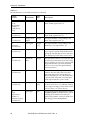
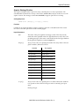
Lead Finder Record Options
➊
➋
➌
➍
➎
➏
Shows the name of this lead finder record and the date it was created or last modified.
Select ✔ TopLevel to have this tool displayed in pick lists of vision tools. Select ✔ Show at
Runtime if you want the tool graphics for the lead finder displayed when a sequence using
this tool is executed.
Enter the picture record to be used by this finder tool.
Choose this button to display a pop-up window from which you can edit the absolute values
of the primary ruler.
Select this button to make the tool relative to a vision frame.
If
Binary is selected, the first lead will be searched for based on the binary image. Use the
slide bar to set the binary threshold.
If
Edge is selected, the first lead will be searched for based on the grayscale image. Use the
slide bar to set the difference in graylevel values that must be detected before an edge is found.
Indicate whether the background is light or dark relative to the surface mount device.
➐
Enter the size of the search areas for individual leads (can also be set using the search area drag
handles).
Enter the effort level to use when searching for a lead. Higher effort levels require more
processing time. (Adept recommends 100% unless vision processing time is critical.)
Individual leads are searched for based on the grayscale image. Use the slide bar to set the
difference in graylevel values required to detect an edge.
➑
In the Minimum and Maximum data boxes, enter the minimum and maximum acceptable lead
width and spacing. If any of the leads do not fall within these values, the inspection will fail.
In the Number of Leads data box, enter the number of leads that should be searched for. If all
the leads are not found, the inspection will fail.
In the Nominal data boxes, enter the ideal values the lead width and spacing should have.
The Result information box shows the average width and spacing of the leads.
➒
Displays the center of the calculated line (centered on the first lead) and the angle with respect
to the vision X-axis of the calculated line.
AIM PCB User’s & Reference Guide, Rev. A
35
Chapter 6 - Special PCB Vision Tools
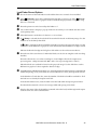
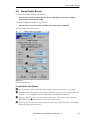
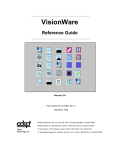
Figure 6-3 shows a typical lead finder tool inspecting the first five leads on a surface mount device.
Calculated line
Figure 6-3
Lead Finder Tool Example
6.4
Frame Finder Tool
This tool uses the results of four line class tools to calculate a reference frame for rectangular parts.
The four line tools locate the four sides of a rectangle and are used to calculate two diagonal
corners. The frame calculated from these two corners has the X-axis pointing at the first corner and
is centered between the two opposing corners. The line class tools that can be used to calculate the
corners of the rectangle are listed in the VisionWare User’s Guide.
Frame finders have two primary uses. The first is to inspect gripped parts and calculate the
difference between the true center of the gripper and the actual center of the part. The second use
is to locate the true center of a part location on an assembly.
This vision tool is used primarily for the REFINE vision, AND vision, and LOCATE vision
clauses of the TRANSFER.FP statement.
36
AIM PCB User’s & Reference Guide, Rev. A
Frame Finder Record
6.5
Frame Finder Record
To create a new frame finder record, perform:
Edit ➡ Vision ➡ Edit ➡ New Record
Record Types: Frame Finder ➡ OK
➡ enter frame finder record name ➡ Other
To edit an existing frame finder record, perform:
Edit
➡ Vision ➡ Seek ➡ Index ➡ double-click “frame finder record name”
The following screen is displayed:
➋
➊
➌
➍
➎
➏
Figure 6-4
Frame Finder Record
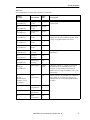
Frame Finder Tool Options
➊
➋
➌
➍
Shows the name of this frame finder record and the date it was created or last modified.
Select this option to have this tool displayed in pick lists of vision tools (for example, when the
REFINE vision argument is double clicked from a TRANSFER.FP statement).
Select two line class vision records to form the first corner of the frame. Unless otherwise
indicated by item ➎, the positive X-axis will point at this corner.
Select two line class vision records to form the second corner of the frame. This corner must be
diagonally opposite from corner 1.
AIM PCB User’s & Reference Guide, Rev. A
37
Chapter 6 - Special PCB Vision Tools
➎
➏
If you do not want the calculated center to be exactly the center of the found frame, indicate
the desired offsets in the X and Y data boxes. To change the rotation of the computed frame,
enter a value in the RZ data box.
Shows the actual value of the frame center and rotation (including any offsets specified in item
➎).
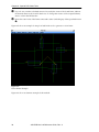
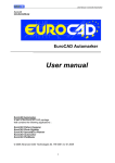
Figure 6-5 shows an example of using four lead finder tools to generate a vision frame.
Figure 6-5
Frame Finder Example
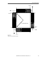
Figure 6-6 shows an alternate example of this method.
38
AIM PCB User’s & Reference Guide, Rev. A
Frame Finder Record
Line 4
Line 1
Calculated frame
Line 3
Line 2
Figure 6-6
Alternate Frame Finder Example
AIM PCB User’s & Reference Guide, Rev. A
39
Chapter 7
Customizing Overview
7.1
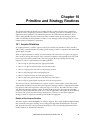
Overview
The Printed Circuit Board (PCB) application is an addition to the standard MotionWare
application. All of the MotionWare statements and databases are available for use in addition to
the PCB-specific statements and databases. If the vision or conveyor tracking options are present,
the MotionWare vision server and conveyor manager tasks are used.
A detailed description of the AIM PCB Application Module is presented in this manual. This
application module requires an AIM system with the MotionWare Module; it supports the optional
Vision Module.
Individuals who wish to customize the AIM system—to provide an interface to applicationspecific hardware or to enhance the system with special algorithms—should use this manual. This
manual contains detailed information regarding the internal organization of the software, the data
structures, and the databases.
An understanding of the information contained in the remainder of this document is not required
in order to operate the AIM system. For a description of how to operate the AIM system, please refer
to the previous chapters and to the MotionWare User’s Guide or the VisionWare User’s Guide.
7.2
Prerequisite Background Information
Before reading this manual, we recommend that you first become familiar with the following
documents:
• MotionWare User’s Guide/MotionWare Reference Guide
These manuals describe in detail the general-purpose robot control routines and data
structures used by the AIM MotionWare Module.
NOTE: AIM PCB is an add-on module for MotionWare.
• V+ Reference Guide
This manual describes the V + robot control and programming system. Since all of the AIM
software is written in the V+ programming language, most customizers will find it necessary
to have a good working knowledge of the V+ programming language. In particular,
customizers wishing to make use of the advanced features of the operator interface or those
wishing to add new statements or strategy routines will find it necessary to understand V+.
However, simple changes to the operator interface (or the addition of new menu pages) can
be accomplished without knowledge of the V+ programming language.
AIM PCB User’s & Reference Guide, Rev. A
41
Chapter 7 - Customizing Overview
• AIM Customizer’s Reference Guide
This manual describes in detail the structure of the AIM baseline software and how to
customize it.
• AdeptVision VME User’s Guide/AdeptVision Reference Guide
These manuals describe all the aspects of the V+ programming system that pertain to the
AdeptVision VME system.
• VisionWare User’s Guide/VisionWare Reference Guide
These manuals describe in detail the general-purpose vision routines and data structures
used by the AIM VisionWare Module.
If your AIM system includes additional system modules, you should also refer to the user’s guide
and reference guide for each of those modules.
7.3
Databases
The PCB databases and type codes are listed below:
7.4
Code
Database
Name
Type
Variable
Database
Variable
Global File
Name
md
Module
md.ty
md.db[]
pcbmod.db
as
Assembly
as.ty
as.db[]
None
fd
Feeder
fd.ty
fd.db[ ]
feeder.db
pa
Part
pa.ty
pa.db[ ]
part.db
pt
Part Type
pt.ty
pt.db[ ]
parttype.db
vc
Camera
vc.ty
vc.db[ ]
vcampcb.db
Overview of the AIM PCB Module
The AIM PCB Module is a collection of programs, databases, and menu pages that direct robot
devices to assemble printed circuit boards.
The major components of the AIM PCB Module are:
1. High-level statements that specify which parts are to be transferred to which locations on a
printed circuit board
2. Strategy routines that determine how parts are acquired from feeders and inserted into or
placed on the circuit board
3. A collection of databases that contain data about the parts, feeders, and circuit boards
4. Menu files that permit these databases to be displayed and that also permit robot-related cell
control operations
5. High-level statements and support routines for interfacing with the AIM Vision Module
6. Custom vision operation routines for inspecting component leads and pad arrays, and for
locating components and fiducial marks
42
AIM PCB User’s & Reference Guide, Rev. A
Overview of the AIM PCB Module
These components are used along with the components supplied with MotionWare.
Database Summary
Table 7-1 contains a brief summary of the databases that are included with the PCB Module. These
databases are in addition to the standard AIM baseline databases and the databases for the AIM
MotionWare Module. (Refer to the respective reference guides for information on those
databases.)
Table 7-1
Database Descriptions
Database
Description
Assembly
This database describes the circuit board locations where parts are placed and
the motions parameters used to place the part. It contains the destination
locations (that is, part attachment locations) for a single assembly.
Feeder
This database describes the feeders from which parts are obtained and the I/O
signals and parameters used to operate the feeders.
Part
This database describes the part type and part feeder for each part to be used in
the assemblies.
Part Type
This database describes the assembly parameters and strategy routines for
acquiring, inserting, and rejecting each type of part.
Camera
The vision camera calibration database. Optional in PCB. The global camera
database for PCB is different from the standard database in MotionWare.
Tool
The standard MotionWare tool database is augmented to describe the
I/O signals used to operate the gripper. Refer to Table 8-9 on page 64 for
details.
AIM PCB User’s & Reference Guide, Rev. A
43
Chapter 7 - Customizing Overview
Menu Summary
Table 7-2 contains a brief summary of the menus that are included with the PCB Module.
Table 7-2
Menu Descriptions
Menu
Description
ASM.MNU
Displays the data for the Assembly database.
FEEDER.MNU
Displays the data for the Feeder database.
PART.MNU
Displays the data for the Part database.
PARTTYPE.MNU
Displays the data for the Part Type database.
PCBVIS.MNU
Displays the custom vision operation records in the Vision database.
7.5
Runtime Routines
The runtime routines (“the runtime”) are the software routines that are responsible for translating
assembly data and processing information into robot and cell hardware commands to assemble
circuit boards. These routines have available to them all the V+ robot control and language
instructions.
The top-level routine of each task that executes a sequence is the sequence scheduler and executer
(“the scheduler”). The scheduler is responsible for determining which assembly sequence is to be
run and how many times it is to be run. Once a sequence is selected, the scheduler executes the
sequence by extracting individual statements from the Sequence database and calling the
appropriate routines to execute each statement.
The statement routines make up the next layer of software. These are the V+ routines that are
called by the scheduler to execute individual AIM sequence statements. There is one statement
routine for each type of AIM statement. Each statement routine is passed a predetermined set of
parameters and performs a single assembly operation. In theory, a statement routine could be
implemented entirely with unique software that is referenced only by that one statement. In fact,
most statement routines rely heavily upon a library of “statement primitives”, which implement
many common high-level actions. The statement routines used by the PCB Module are described
in Chapter 9.
The statement primitives form the next layer of software. This library of routines is called by the
statement routines to perform common actions such as acquiring a part from a feeder or inserting
a part into an assembly. Each statement primitive typically combines several robot motions with
cell control operations, and possibly even sensory feedback, to perform what is a fairly high-level
action. The capabilities provided by the statement primitives can be enhanced by adding new
primitives or by adding new “strategy routines”, which are called by the statement primitives to
deal with special hardware requirements.
In some situations, new primitives may have to be added to the system. To assist in the writing of
new primitives, the source code for the standard primitives is provided with the PCB Module.
New primitives can be written by copying and modifying the standard primitives, or they may be
written as entirely new routines.
It should be kept in mind that primitives are not fundamentally required for the implementation
of new statements. Primitives are simply general-purpose routines that perform high-level actions
44
AIM PCB User’s & Reference Guide, Rev. A
Runtime Routines
that are used often. If an existing primitive can be employed in the development of a new
statement, its use will obviously reduce the development effort. As such, primitives are not always
called from statement routines. If required, a primitive can be called by another primitive or from
any other runtime routine.
See the “dictionary” of runtime routines in Chapter 9 for detailed explanations of the calling
sequences for the routines described in this section.
Strategy routines deal with the application-specific aspects of the assembly process. These
routines directly operate the robot gripper and other hardware devices and interface with special
sensors such as those for detecting jammed parts or for monitoring forces. Strategy routines also
perform special algorithms for acquiring a part from a feeder or searching for an insertion
location. The strategy routines are named in the Part Type database and can be changed easily by
the user.
The strategy routines make use of standard AIM routines that are supplied with the AIM Baseline
Module, the MotionWare Module, or other optional AIM modules. See the respective reference
guides for these modules for complete descriptions of standard AIM routines and low-level
primitives.
AIM PCB User’s & Reference Guide, Rev. A
45
Chapter 8
Databases
This chapter describes the databases used by the PCB Application Module. It also provides
detailed information on databases that are unique to this application.
8.1
Identification Numbers
Table 8-1 lists all the databases added by the PCB Module, their type numbers, and the global
variables that can be used to refer to the databases.
Table 8-1
Database Identification Numbers
Resource
Name
Type Variable,
Database Variable,
Module File Ext.
Type
Number
Description
Assembly
as.ty
as.db[TASK( )]
.as
33
Defines the location where a part is to
be placed and how to place it. There is
no global assembly database.
Feeder
fd.ty
fd.db[TASK( )]
.fd
26
Defines the feeders used by the system.
Global database is FD.DB.
Part
pa.ty
pa.db[TASK( )]
.pa
25
Each record in this database defines the
parameters for a single part (part name,
type, and feeders for the part). Global
database is PA.DB.
Part Type
pt.ty
pt.db[TASK( )]
.pt
24
Each record in this database defines a
single type of part (specifies attributes
that are commonly shared among
multiple parts). Global database is
PT.DB.
Tool
to.ty
to.db[TASK( )]
.to
28
Defines the tool offsets for a robot.
Global database is TOOL.DB.
NOTE: Whenever possible, use the variables listed in Table 8-1 in place of
explicit database numbers. Future AIM systems may use different
numbers to refer to the databases, but the variable names will be retained
with appropriate values.
AIM PCB User’s & Reference Guide, Rev. A
47
Chapter 8 - Databases
8.2
Assembly Database
Each record in an Assembly database defines a location where a part is to be placed and how the
part is to be placed. The record fields define the name of the location and the robot motion
parameters used while moving to the location.
All the record fields are listed below, in the order in which they occur within a record. The fields
are summarized in Table 8-2. The data in a record can be accessed from an application program by
using the V+ variable names shown in the first column. The global variable for accessing the
Assembly database is as.db[TASK( )].
Table 8-2
Record Definition for the Assembly Database
Field #,
Variable
Field Name
Type,
Size
Description
0
cc.name
name
name
15
A standard AIM name that identifies a part
location in this assembly. This is the primary
sort field and must be unique in this database.
This name is referenced in a statement to
specify the destination of a part.(1)
1
cc.update
update date
date/time
4
The date and time when this record was last
modified. This field is automatically set to the
current date when the record is edited.
2
cc.device
device
integer
2
The number of the robot device associated with
this assembly location. This field is set to one
for single-robot systems.
3
as.loc.frame
reference
frame name
name
15
The name of the Frame database record that
defines the frame for this location. This field is
used only if the location type bits indicate
relative to a named frame.(1)
4
as.loc
location
transform
48
The basis location for the next motion block.
This corresponds to the location of the tool
when the part is inserted into the assembly
with no approach offset.(5)
5
as.app.strategy
approach
strategy
name
name
1
The name of the approach strategy routine or
sequence.(1, 3)
6
as.loc.data
approach
integer
2
Start of a standard robot motion parameter
block for the motion to approach the part
location. See the MotionWare Reference Guide for
details.(2)
48
AIM PCB User’s & Reference Guide, Rev. A
Assembly Database
Table 8-2
Record Definition for the Assembly Database (Continued)
Field #,
Variable
Field Name
Type,
Size
7
as.app.mve
approach
motion bits
integer
2
8
approach
speed
real
4
9
approach
acceleration
byte
1
10
approach
deceleration
byte
1
11
approach
rotational
speed
real
4
12
approach
profile
byte
1
13
as.app.seqnum
[approach
sequence]
integer
2
(3, 6)
14
location
configuration
byte
1
15
location
type bits
integer
2
Standard location parameter block for the
assembly location. See the MotionWare
Reference Guide.(3)
16
as.loc.frm.rec
[location
frame]
integer
2
(3, 6)
17
as.loc.strategy
location
strategy
name
name
1
The name of the location strategy routine or
sequence.(1, 3)
18
[location]
byte
1
Start of a standard robot motion parameter
block for the motion to the part location. See
the MotionWare Reference Guide.(4)
Description
Part of the standard robot motion parameter
block for the motion to approach the part
location. See the MotionWare Reference Guide.(3)
AIM PCB User’s & Reference Guide, Rev. A
49
Chapter 8 - Databases
Table 8-2
Record Definition for the Assembly Database (Continued)
Field #,
Variable
Field Name
Type,
Size
19
as.loc.mve
location
motion bits
integer
2
20
location
speed
real
4
21
location
acceleration
byte
1
22
location
deceleration
byte
1
23
location
rotational
speed
real
4
24
location
profile
byte
1
25
as.loc.seqnum
[location
sequence]
integer
2
(3, 6)
26
as.dep.strategy
depart
strategy
routine
name
1
The name of the depart strategy routine or
sequence.(1, 3)
27
depart
integer
2
Start of a standard robot motion parameter
block for the motion to depart from the part
location. See the MotionWare Reference Guide.(2)
28
as.dep.mve
depart
motion bits
integer
2
29
depart speed
real
4
Part of the standard robot motion parameter
block for the motion to depart from the part
location. See the MotionWare Reference Guide.(3)
30
depart
acceleration
byte
1
31
depart
deceleration
byte
1
32
depart
rotational
speed
real
4
33
depart
profile
byte
1
34
as.dep.seqnum
[depart
sequence]
integer
2
50
Description
Part of the standard robot motion parameter
block for the motion to the part location. See
the MotionWare Reference Guide.(3)
(3, 6)
AIM PCB User’s & Reference Guide, Rev. A
Feeder Database
Table 8-2
Record Definition for the Assembly Database (Continued)
Field #,
Variable
Field Name
Type,
Size
35
as.user
(as.user.num=
Number of
user
parameters)
user
parameter 1
real
4
36
user
parameter 2
real
4
Description
These fields contain real values that are
available for general use by the system
customizer.(6)
Notes:
1.
2.
3.
4.
5.
6.
8.3
If this field is modified, the database is marked for updating.
First field of motion block with approach.
Field in motion block, not first.
First field of motion block, no approach.
Field is edited even if defined during the “edit all” mode of walk-thru training.
This field is specified in a linking rule and is filled in automatically by the linker.
Feeder Database
Feeders are the source of all parts handled by the PCB Module. This section presents a detailed
description of the records in the Feeder database, which describes all the feeders used by the
system.
Each record in this database defines a single feeder. The fields in a Feeder record define the
location of the feeder and the parameters required to operate the feeder.
All the record fields are listed and summarized in Table 8-3, in the order in which they occur
within a record. The data in a record can be accessed from an application program by using the V+
variable names shown in the first column. The global variable for accessing the Feeder database is
fd.db[TASK( )].
Table 8-3
Record Definition for the Feeder Database
Field #,
Variable
0
cc.name
Field Name
name
Type,
Size
name
15
Description
A standard name that identifies the feeder.
This is the primary sort field and must be
unique in this database. This name is used
by the AIM linker to link Part records to
their associated Feeder records. This name
is also displayed to the operator during
training and when reporting errors.(1)
AIM PCB User’s & Reference Guide, Rev. A
51
Chapter 8 - Databases
Table 8-3
Record Definition for the Feeder Database (Continued)
Field #,
Variable
Field Name
Type,
Size
Description
1
cc.update
update date
date/
time
4
The date and time when this record was last
modified. This field is automatically set to
the current date when the record is edited.
2
cc.device
device
integer
2
The number of the robot device associated
with this record. For AIM systems with only
one device, this field is normally set to 1.
3
cc.page.name
menu page
name
name
15
The name of the menu page (in the file
FEEDER.MNU) used to display this feeder
record. If this name is blank, the page
named “main” is used by default.
4
fd.loc.frame
reference
frame name
name
15
The name of the Reference Frame database
record that is the frame for this location.
This field is used only if the location type
bits indicate “relative to a named frame”.(1)
5
fd.loc
location
transform
48
The basis location for the next motion block.
This corresponds to the location of the tool
when the part is gripped while being
removed from the feeder.(2)
6
fd.app.strategy
approach
strategy
name
name
1
The name of the approach strategy name or
sequence.(1, 4)
7
fd.loc.data
approach
integer
2
Start of a standard robot motion parameter
block for the motion to approach the part
grip location. See the MotionWare Reference
Guide.(3)
52
AIM PCB User’s & Reference Guide, Rev. A
Feeder Database
Table 8-3
Record Definition for the Feeder Database (Continued)
Field #,
Variable
Field Name
Type,
Size
8
fd.app.mve
approach
motion bits
integer
2
9
approach
speed
real
4
10
approach
acceleration
byte
1
11
approach
deceleration
byte
1
12
approach
rotational
speed
real
4
13
approach
profile
byte
1
14
fd.app.seqnum
[approach
sequence]
integer
2
(8)
15
location
configuration
byte
1
16
location type
bits
integer
2
Standard location parameter block for the
feeder location. See the MotionWare
Reference Guide.(4)
17
fd.loc.frm.rec
[location
frame]
integer
2
(8)
18
fd.loc.strategy
location
strategy
name
name
1
The name of the location strategy name or
sequence.(1, 4)
19
[location]
byte
1
Start of a standard robot motion parameter
block for the motion to the part grip
location. See the MotionWare Reference
Guide.(5)
Description
Part of the standard robot motion
parameter block for the motion to approach
the part grip location. See the MotionWare
Reference Guide.(4)
AIM PCB User’s & Reference Guide, Rev. A
53
Chapter 8 - Databases
Table 8-3
Record Definition for the Feeder Database (Continued)
Field #,
Variable
Field Name
Type,
Size
20
fd.loc.mve
location
motion bits
integer
2
21
location
speed
real
4
22
location
acceleration
byte
1
23
location
deceleration
byte
1
24
location
rotational
speed
real
4
25
location
profile
byte
1
26
fd.loc.seqnum
[location
sequence]
integer
2
(4, 7)
27
fd.dep.strategy
depart
strategy
name
name
1
The name of the depart strategy name or
sequence.(1, 4)
28
depart
integer
2
Start of a standard robot motion parameter
block for the motion to depart from the part
grip location. See the MotionWare Reference
Guide.(3)
29
fd.dep.mve
depart
motion bits
integer
2
30
depart speed
real
4
Part of the standard robot motion
parameter block for the motion to depart
from the part grip location. See the
MotionWare Reference Guide.(4)
31
depart
acceleration
byte
1
32
depart
deceleration
byte
1
33
depart
rotational
speed
real
4
34
depart
profile
byte
1
35
fd.dep.seqnum
[depart
sequence]
integer
2
54
Description
Part of the standard robot motion
parameter block for the motion to the part
grip location. See the MotionWare Reference
Guide.(4)
(4, 7)
AIM PCB User’s & Reference Guide, Rev. A
Feeder Database
Table 8-3
Record Definition for the Feeder Database (Continued)
Field #,
Variable
Field Name
Type,
Size
Description
36
fd.trn.frame
transit
reference
frame name
name
15
The name of the Reference Frame database
record that is the frame for the transit
location (described below). This field is
used only if the transit type bits indicate
“relative to a named frame”.(1)
37
fd.transit
transit
transform
48
Optional basis location through which the
robot tool tip will move on the way to and
from the feeder. If not defined, this field is
ignored and no intermediate transit motion
occurs.(2, 6, 7)
38
fd.trn.strategy
transit
strategy
name
name
1
The name of the transit strategy routine or
sequence.(1, 4)
39
fd.transit.data
[transit]
byte
1
Start of a standard robot motion parameter
block for the motion to the transit location.
See the MotionWare Reference Guide.(5)
40
fd.trn.mve
transit
motion bits
integer
2
41
transit speed
real
4
Part of the standard robot motion
parameter block for the motion to the
transit location. See the MotionWare
Reference Guide.(4)
42
transit
acceleration
byte
1
43
transit
deceleration
byte
1
44
transit
rotational
speed
real
4
45
transit profile
byte
1
46
fd.trn.seqnum
[transit
sequence]
integer
2
(4, 7)
47
transit
configuration
byte
1
48
transit type
bits
integer
2
Standard location parameter block for the
transit location. See the MotionWare
Reference Guide.(4)
49
fd.trn.frm.rec
[transit
frame]
integer
2
(4, 7)
AIM PCB User’s & Reference Guide, Rev. A
55
Chapter 8 - Databases
Table 8-3
Record Definition for the Feeder Database (Continued)
Field #,
Variable
Field Name
Type,
Size
Description
50
fd.opr
(fd.opr.num=
Number of
arguments in
array)
enable signal
integer
2
The signal number corresponding to the
field “enable signal name”.(7)
51
(see Table 8-4)
ready signal
integer
2
The signal number corresponding to the
field “ready signal name”.(7)
52
(see Table 8-4)
empty alarm
signal
integer
2
The signal number corresponding to the
field “alarm signal name”.(7)
53
fd.user.sig
(see Table 8-4)
user signal
integer
2 [3]
The signal number corresponding to the
field array “user signal name”.(7)
54
(see Table 8-4)
retry count
integer
2
The maximum number of times AIM should
try to acquire a part from the feeder before
giving up and signaling an error. AIM does
not attempt any retries if the value is zero.
55
(see Table 8-4)
maximum
time
integer
2
The maximum number of seconds that AIM
should wait for the feeder to become ready
before signaling an error. This value should
be greater than the cycle time (described
below) or errors may be signaled during
normal operation.
56
(see Table 8-4)
cycle time
real
4
The time (in seconds) required for the
feeder to become ready after it has fed a
part. AIM will wait for at least this long
before attempting to access the feeder after
a part has been extracted, even if the partready signal indicates a part is ready.
57
(see Table 8-4)
pickup offset
real
4 [2]
These two array elements contain the X and
Y offset values (in tool coordinates) used by
some acquire strategy routines. If the values
are zero, there is no offset value.(2)
58
fd.pal
(rb.pal.num=
Number of
elements in array)
(see Table 8-5)
pallet type
byte
1
A type code used by the primitive routine
rn.update.pallet( ) to determine the order in
which parts should be removed from a
pallet. This primitive routine is called from
the strategy routine rn.ac.pallet( ).
56
AIM PCB User’s & Reference Guide, Rev. A
Feeder Database
Table 8-3
Record Definition for the Feeder Database (Continued)
Field #,
Variable
Field Name
Type,
Size
Description
59
(see Table 8-5)
pallet row
count
integer
2
The number of rows, columns, and layers
on the pallet.
60
(see Table 8-5)
pallet col
count
integer
2
61
(see Table 8-5)
pallet layer
count
integer
2
62
(see Table 8-5)
pallet row
index
integer
2
63
(see Table 8-5)
pallet col
index
integer
2
64
(see Table 8-5)
pallet layer
index
integer
2
65
(see Table 8-5)
pallet row
spacing
real
4
66
(see Table 8-5)
pallet col
spacing
real
4
67
(see Table 8-5)
pallet layer
spacing
real
4
68
fd.sig.pal
(see Table 8-5)
pallet signal
integer
2 [3]
An array of three V+ output or soft signal
numbers that are asserted when a row,
column, or layer reaches its maximum
index value. If a signal number is zero, it is
ignored.(7)
69
fd.user
(fd.user.num =
Number of user
parameters)
user
parameter 1
real
4
This is a group of four fields (not a database
array) that are available for general use.
These fields are not used by standard AIM
routines.
70
user
parameter 2
real
4
71
user
parameter 3
real
4
72
user
parameter 4
real
4
The row, column, and layer indexes for the
next part to be accessed from a pallet. These
values are updated after each access.
The spacing between pallet rows, columns,
and layers.
AIM PCB User’s & Reference Guide, Rev. A
57
Chapter 8 - Databases
Table 8-3
Record Definition for the Feeder Database (Continued)
Field #,
Variable
Field Name
Type,
Size
73
fd.enable.name
enable signal
name
string
15
A number or database record name that
specifies the input signal that determines
whether or not the feeder is enabled for
operation. If the signal is FALSE, indicating
the feeder is not enabled, AIM will not
attempt to acquire a part from this feeder. If
the signal number is zero, AIM assumes the
feeder is not enabled.(1)
74
fd.ready.name
ready signal
name
string
15
A number or database record name that
specifies the input signal that specifies that
the feeder has a part ready to be acquired. If
the signal number is negative, the logic of
the signal is inverted (that is, a FALSE signal
then indicates a part is ready). If the signal
number is zero, AIM assumes that the feeder
is always ready.(1)
75
fd.alarm.name
alarm signal
name
string
15
A number or database record name that
specifies the output signal that will be
asserted to activate an alarm when the
feeder becomes empty or a feed error
occurs. If the number is negative, the logic
of the signal is inverted (that is, a FALSE
signal then indicates a part is ready). If the
number is zero, AIM does not assert any
output signal.(1)
76
fd.usig.name
user signal
name
string
15 [3]
Names associated with the fields in “user
signal”.(1)
77
fd.sig.pal.name
pallet signal
name
string
15 [3]
Names associated with the fields in “pallet
signal”.(1)
Description
Notes:
1.
2.
3.
4.
5.
6.
7.
58
If this field is modified, the database is marked for updating.
Field is edited even if defined during the “edit all” mode of walk-thru training.
First field of motion block with approach.
Field in motion block, not first.
First field of motion block, no approach.
Field is optional at runtime.
This field is specified in a linking rule and is filled in automatically by the linker.
AIM PCB User’s & Reference Guide, Rev. A
Feeder Database
Table 8-4
Offset Values From Feeder Database Field 50 (fd.opr)
Value
Field
Reference
fd.opr.enable
0
50
fd.opr.ready
1
51
fd.opr.alarm
2
52
fd.opr.usig.1
3
53
fd.opr.usig.2
4
53
fd.opr.usig.3
5
53
fd.opr.retry
6
54
fd.opr.timeout
7
55
fd.opr.time
8
56
fd.opr.xoffset
9
57
fd.opr.yoffset
10
57
Name
Table 8-5
Offset Values From Feeder Database Field 58 (fd.pal)
Value
Field
Reference
rb.pal.type
0
58
rb.pal.row.cnt
1
59
rb.pal.col.cnt
2
60
rb.pal.lay.cnt
3
61
rb.pal.row.idx
4
62
rb.pal.col.idx
5
63
rb.pal.lay.idx
6
64
rb.pal.row.spc
7
65
rb.pal.col.spc
8
66
rb.pal.lay.spc
9
67
rb.pal.sig
10
68
Name
Refer to the MotionWare Reference Guide section 3.5 for more details on pallet parameters.
AIM PCB User’s & Reference Guide, Rev. A
59
Chapter 8 - Databases
8.4
Part Database
Each record in this database defines a single part. The fields in a record define the part name, type,
and feeders for the part. Internal fields in the Part database are filled in during linking.
A single part can have multiple feeders, but normally a feeder feeds only a single part. For feeders
that feed different parts, the same feeder can be referenced by multiple Part database records.
When using this feature, it is the responsibility of the system customizer to keep track of what part
will be fed next.
All the record fields are listed and summarized in Table 8-6, in the order in which they occur
within a record. The data in a record can be accessed from an application program by using the V+
variable names shown in the first column. The global variable for referencing the Part database is
pa.db[TASK( )].
Table 8-6
Record Definition for the Part Database
Field #,
Variable
Field Name
Type,
Size
Description
0
cc.name
name
name
15
A standard name that identifies this part. This is
the primary sort field and must be unique in this
database. This name is referenced in assembly
sequence statements.(1)
1
cc.update
update date
date/
time
4
The date and time when this record was last
modified. This field is automatically set to the
current date when the record is edited.
2
pa.typename
part type
name
name
15
A standard name that specifies the type of this
part. This name must be present in the Part Type
database.(1)
3
pa.type
[part type]
integer
2
The number of the record in the Part Type
database that corresponds to the part type name.
This value is automatically computed by the
linker.
4
pa.feedername
feeder
name
name
15 [4]
An array of standard names that specify feeders
for this part. The names must be present in the
Feeder database.(1)
5
pa.feeder
(pa.feeder.num=
Number of
elements in
feeder name/
link)
[feeder]
integer
2 [4]
The numbers of the records in the Feeder
database that correspond to the feeder names
(see above). The acquire routine uses these
values when searching for a feeder. These values
are computed during linking.
Notes:
1. If this field is modified, the database is marked for updating.
60
AIM PCB User’s & Reference Guide, Rev. A
Part Type Database
8.5
Part Type Database
Each record in this database defines a single type of part. A Part Type record specifies attributes
that are commonly shared among multiple parts.
The fields in a record define the part type name; the names of routines or sequences used to
acquire, insert, and reject this type of part; the speed factor to be used while holding this type of
part; the name of the robot tool appropriate for this type of part; and parameters for use by
insertion routines.
All the record fields are listed and summarized in Table 8-7, in the order in which they occur
within a record. The data in a record can be accessed from an application program by using the V+
variable names shown in the first column. The global variable for referencing the Part Type
database is pt.db[TASK( )].
Table 8-7
Record Definition for the Part Type Database
Field #,
Variable
Field Name
Type,
Size
Description
0
cc.name
name
name
15
A standard name that identifies this part type.
This is the primary sort field and must be
unique in this database. This name is
referenced in the Part database.(1)
1
cc.update
update date
date/
time
4
The date and time when this record was last
modified. This field is automatically set to the
current date when the record is edited.
2
pt.ac.strategy
acquire
strategy
name
name
15
A standard name that specifies the name of
the V+ strategy routine or sequence that is
called to acquire parts of this type from their
feeders. (For details, see the discussion of the
part-acquisition routine in Chapter 10.)(1)
3
pt.in.strategy
insert
strategy
name
name
15
A standard name that specifies the name of
the V+ strategy routine or sequence that is
called to insert a part of this type into an
assembly. (For details, see the discussion of
the part-insertion routine in Chapter 10.)(1)
4
pt.rj.strategy
reject
strategy
name
name
15
A standard name that specifies the name of
the V+ strategy routine or sequence that is
called to reject a part of this type. (For details,
see the discussion of the part-reject routine in
Chapter 10.)(1)
5
pt.toolnam
tool name
name
15
A standard name that specifies the tool to be
used when handling parts of this type. This
name identifies the record in the Tool
database that contains data defining the tool.
This name must be present in the Tool
database. See the description of the Tool
database in section 8.6.(1)
AIM PCB User’s & Reference Guide, Rev. A
61
Chapter 8 - Databases
Table 8-7
Record Definition for the Part Type Database (Continued)
Field #,
Variable
Field Name
Type,
Size
Description
6
pt.tool
[tool]
integer
2
The number of the record in the Tool database
that describes the tool to be used for this
part.(2)
7
pt.flags
flags
integer
2
These fields define parameters that can be
used by an insertion strategy routine. See
Table 8-8 for flag bit definitions. See the
discussion of part-insertion strategy routines
in Chapter 10 for details on motion blocks.
8
pt.ac.seqnum
[acquire
sequence]
integer
2
Number of the acquire, insert, or reject
sequence if field 2, 3, or 4 specifies a strategy
sequence.(2)
9
pt.in.seqnum
[insert
sequence]
integer
2
Number of the acquire, insert, or reject
sequence if field 2, 3, or 4 specifies a strategy
sequence.(2)
10
pt.rj.seqnum
[reject
sequence]
integer
2
Number of the acquire, insert, or reject
sequence if field 2, 3, or 4 specifies a strategy
sequence.(2)
11
pt.ac.fp.name
acquire
force process
name
name
15
A standard AIM name that specifies a record
in the force process database. This is used
when acquiring, inserting, or rejecting a
part.(1)
12
pt.in.fp.name
insert force
process
name
name
15
A standard AIM name that specifies a record
in the force process database. This is used
when acquiring, inserting, or rejecting a
part.(1)
13
pt.rj.fp.name
reject force
process
name
name
15
A standard AIM name that specifies a record
in the force process database. This is used
when acquiring, inserting, or rejecting a
part.(1)
14
pt.ac.fprocess
[acquire
force
process]
integer
2
The record number corresponding to the field
“acquire force process name”.(2)
15
pt.in.fprocess
[insert force
process]
integer
2
The record number corresponding to the field
“insert force process name”.(2)
16
pt.rj.fprocess
[reject force
process]
integer
2
The record number corresponding to the field
“reject force process name”.(2)
Notes:
1. If this field is modified, the database is marked for updating.
2. This field is computed during linking.
62
AIM PCB User’s & Reference Guide, Rev. A
Part Type Database
Table 8-8
Flag Bits Defined in pt.flags
Name
Setting
Description
pt.flb.ac.rtn
1
Bit number set if acquire uses a V+ routine. Otherwise,
it uses an AIM sequence.
pt.flb.in.rtn
2
Bit number set if insert uses a V+ routine. Otherwise, it
uses an AIM sequence.
pt.flb.rj.rtn
3
Bit number set if reject uses a V+ routine. Otherwise, it
uses an AIM sequence.
pt.fl.ac.fp
^H10
Bit mask set if acquire uses force processing.
pt.fl.in.fp
^H20
Bit mask set if insert uses force processing.
pt.fl.rj.fp
^H40
Bit mask set if reject uses force processing.
AIM PCB User’s & Reference Guide, Rev. A
63
Chapter 8 - Databases
8.6
Tool Database
The Tool database describes multiple tools or grippers that are used by the robot when it handles
parts. Each record in this database defines a single tool. The fields in a record define the robot
(motion device) associated with the record, the offset from the end of the robot to the tool grip
point (tool transformation), and tool controls (I/O signals and delay times) for up to three
different tool configurations.
All the record fields are listed in the order in which they occur within a record. The data in a
record can be accessed from an application program by using the V+ variable names shown in the
first column.
Table 8-9
Record Definition for the Tool Database
Field #,
Variable
Field Name
Type,
Size
Description
name
name
15
A standard name that identifies this record. This
is the primary sort field and must be unique in
this database.(1)
1
cc.update
update date
date
4
The date this record was last modified. This
field is automatically set to the current date
when the record is edited.
2
cc.device
device
integer
2
The number of the robot (motion device)
associated with this record.
3
to.loc
(to.array.num=
Number of
elements in tool
array)
tool
transformation
transform Each element of this array defines an offset from
48 [3]
the robot tool mounting flange to the actual part
grip point. These transformations should be
defined so that the positive Z-axes of the tools
point in the approach direction. The multiple
array elements are intended to be used with a
tool that changes configuration, such as a
pivoting gripper.
4
to.part.sig.nam
part present
input signal
string
15
A variable database record name that specifies
the input signal to be monitored to determine
when a new object is present at the pickup
location.(1)
5
to.opn.sig.nam
open gripper
output signal
string
15
A variable database record name that specifies
the output signal used to open the robot
gripper.(1)
6
to.cls.sig.nam
close gripper
output signal
string
15
A variable database record name that specifies
the output signal used to close the robot
gripper.(1)
7
to.rai.sig.nam
raise gripper
output signal
string
15
A variable database record name that specifies
the output signal used to raise the robot
gripper.(1)
8
to.low.sig.nam
lower gripper
output signal
string
15
A variable database record name that specifies
the output signal used to lower the robot
gripper.(1)
0
cc.name
64
AIM PCB User’s & Reference Guide, Rev. A
Tool Database
Table 8-9
Record Definition for the Tool Database (Continued)
Field #,
Variable
Field Name
Type,
Size
Description
9
to.opr=
(to.opr.num =
Number of
elements in the
array)
[part present]
integer
2
Start of the standard tool operation values.
Element containing the number of the digital
input signal connected to the part-present
sensor. The signal should be TRUE when a part
is held in the robot gripper. The variable should
be set to zero if no part-present sensor is
connected.(2)
10
[open gripper]
integer
2
Element containing the number of the digital
output signal that opens the robot gripper. The
robot gripper should open when the signal is set
to TRUE. (This signal is controlled as the
complement of the signal to.opr.cls.sig.) The
variable should have the value zero if no opengripper signal is connected.(2)
11
[close gripper]
integer
2
Element containing the number of the digital
output signal that closes the robot gripper. The
robot gripper should close when the signal is set
to TRUE. (This signal is controlled as the
complement of the signal to.opr.opn.sig.) The
variable should have the value zero if no
close-gripper signal is connected.(2)
12
[raise gripper]
integer
2
Element containing the number of the digital
output signal that raises the robot gripper. The
robot gripper should raise when the signal is set
to TRUE. (This signal is controlled as the
complement of the signal to.opr.low.sig.) The
variable should have the value zero if no
raise-gripper signal is connected.(2)
13
[lower gripper] integer
2
Element containing the number of the digital
output signal that lowers the robot gripper. The
robot gripper should lower when the signal is
set to TRUE. (This signal is controlled as the
complement of the signal to.opr.rai.sig.) The
variable should have the value zero if no lowergripper signal is connected.(2)
14
open gripper
delay
real
4
Element containing the time, in seconds, that the
robot should delay after activating an opengripper signal. This delay allows the gripper to
open before the robot begins moving.
15
close gripper
delay
real
4
Element containing the time, in seconds, that the
robot should delay after activating a closegripper signal. This delay allows the gripper to
close before the robot begins moving.
AIM PCB User’s & Reference Guide, Rev. A
65
Table 8-9
Record Definition for the Tool Database (Continued)
Field #,
Variable
Field Name
Type,
Size
16
raise gripper
delay
real
4
Element containing the time, in seconds, that the
robot should delay after activating a raisegripper signal. This delay allows the gripper
position to stabilize before the robot begins
moving.
17
lower gripper
delay
real
4
Element containing the time, in seconds, that the
robot should delay after activating a lowergripper signal. This delay allows the gripper
position to stabilize before the robot begins
moving.
Description
Notes:
1. If this field is modified, the database is marked for updating.
2. This field is specified in a linking rule and is filled in automatically by the linker.
Table 8-10
Offset Values From Tool Database Field 9 (to.opr)
Value
Field
Reference
to.opr.part.sig
0
9
to.opr.opn.sig
1
10
to.opr.cls.sig
2
11
to.opr.rai.sig
3
12
to.opr.low.sig
4
13
to.opr.opn.del
5
14
to.opr.cls.del
6
15
to.opr.rai.del
7
16
to.opr.low.del
8
17
Name
Chapter 9
Statements
This chapter describes the functions and calling sequences of the statement routines that are
defined in the Statement database (STATPCB.DB) distributed with the AIM PCB Application
Module. These statements are considered fundamental for all AIM PCB installations, and they
provide specific examples from which other statements can be developed. These routines may be
called by application software written by a system customizer.
Source code for these routines is provided with this application module. Thus, these routines may
be modified by a system customizer.
CAUTION: In general, AIM routines should not be modified in any way
that changes the calling sequence or the interpretations of the program
parameters. This restriction is required to maintain compatibility with
calls by other AIM routines for which source code is not available.
The descriptions of the statement routines are presented in alphabetical order, with each routine
starting on a separate page. The “dictionary page” for each routine contains the following sections,
as applicable.
Statement Syntax
This section shows the syntax used in the statement.
Function
This is a brief statement of the function of the routine.
Usage Considerations
This section is used to point out any special considerations associated with use of the routine.
Calling Sequence
The format of a V+ CALL instruction for the routine is shown.
CAUTION: The variable names used for the routine parameters are for
explanation purposes only. Your application program can use any
variable names you want when calling the routine.
Input Parameters
Each of the input parameters in the calling sequence is described in detail. For parameters that
have a restriction on their acceptable values, the restriction is specified.
AIM PCB User’s & Reference Guide, Rev. A
67
Chapter 8 - Statements
Output Parameters
Each of the output parameters in the calling sequence is described in detail.
Global Variables
Global variables accessed by the routine are described.
Details
A complete description of the routine and its use is given.
Related Routines
Other AIM routines, which are related to the function of the current routine, are listed.
NOTE: Some of the routines listed may be documented in the reference
guide for a different portion of your AIM system.
68
AIM PCB User’s & Reference Guide, Rev. A
LOCATE.ASSEMBLY
Statement Syntax
LOCATE.ASSEMBLY FRAME frame1 {DEFAULT frame2} {APPROACH path}
LOCATE vision {AT loc1 {loc2 {loc3 {loc4}}}}
{DEPART path} {USING tool}
{OK_SIGNAL variable}
Function
Statement routine for the LOCATE.ASSEMBLY statement. This routine uses vision to determine the
reference frame for an entire assembly based on one to four fiducial marks.
Usage Considerations
This routine must be called from a runtime task and the AIM Vision Module must be loaded.
Calling Sequence
CALL locate.assembly (args[], error)
Input Parameter
args[]
Real array containing the arguments for this statement. The individual
elements are described below:
frame1
[1] Frame database record number that specifies the default reference
frame to be used when positioning the camera to view the fiducial marks.
DEFAULT frame2
[2] Optional Frame database record number, specifying the default
reference frame to be used when positioning the camera to view the
fiducial marks.
APPROACH path
[3] Optional Path database record number that specifies the path to use
when approaching the assembly. The value of this element must be 0 if no
path is specified.
LOCATE vision
[4] Vision database record number, specifying the vision operation to
evaluate in order to locate a fiducial mark. This vision operation must
return “frame” type data.
AT loc1−loc4
[5]−[8] Optional Assembly database record numbers, specifying the
nominal location of additional fiducial marks. The actual fiducial marks
must be visible when the camera is aimed at these locations. These
records are found in the current Assembly database that is associated
with the current sequence.
DEPART path
[9] Optional Path database record number that specifies the path to follow
when departing from the assembly location. The value of this element
must be 0 if no path is specified.
USING tool
[10] Optional Tool database record number that specifies the tool to use
AIM PCB User’s & Reference Guide, Rev. A
69
LOCATE.ASSEMBLY
when performing this transfer operation. The value of this element must
be 0 if the NULL tool is to be used.
OK_SIGNAL variable
[11] An optional code for a Variable database output variable that receives
−1 if the reference frame was successfully computed. Otherwise, it is set
to zero. This argument should be set to the value of the global variable
va.undef.var if the clause is omitted.
Output Parameter
error
Real variable that receives a value indicating whether or not the operation
was successful, and what action should be taken by the calling routine.
See the standard AIM operator error response code values.
Details
This statement uses vision to determine the precise value of the reference frame associated with an
entire assembly. The statement is useful when assembly locations are specified relative to a general
assembly reference frame. Then the problem is to precisely determine the assembly reference
frame before performing a series of part placement operations.
NOTE: You should use the TRANSFER.FP statement to visually determine
the location of a single part in an assembly.
This statement visually locates from one to four fiducial marks on the assembly and uses them to
correct the value for the reference frame. If multiple fiducial marks are used, the position of the
new reference frame is computed so that the centroid of all the database-specified fiducial marks is
positioned at the centroid of all the visually determined fiducial marks.
The orientation of the new reference frame is computed by:
1. The angle of each fiducial mark with respect to the centroid.
2. The difference in angle between the database-specified fiducial marks and the visually
determined fiducial marks.
3. An angular correction that is equal to the weighted average of all the angular differences. The
weight used for each difference is equal to the distance from the centroid to the respective
fiducial mark.
4. The angular correction is applied to the current frame value.
To assist with having this statement driven by CAD data, the locations of the fiducial marks should
be specified relative to a reference frame used by the Assembly database locations. To position a
camera for viewing each fiducial mark, an approximate reference frame is required. This frame
can be specified via input parameter args[2]. If this argument is specified, the current reference
frame is set equal to the value of the specified frame. Otherwise, the current reference frame is
used.
The general operation of this statement is:
1. Open the optional default Frame database record and copy the frame value to the frame/
reference frame.
2. Set the robot tool to the value specified or to NULL.
3. Move along the optional path to the location of the first fiducial mark.
70
AIM PCB User’s & Reference Guide, Rev. A
LOCATE.ASSEMBLY
4. Move so that the fiducial mark is seen by the camera.
5. Locate the fiducial mark using the vision runtime routine rn.vis.pic.list( ). If the vision
operation is successful, save the data for later computation.
6. Loop to step 4 for all the defined fiducial marks.
7. Compute the new reference frame value using the general vision routine vi.fit.frame( ), and
store the value in the Frame database.
8. If no error has occurred, move along the optional depart path.
The following general items should be observed when defining data for this statement:
1. All location data must be taught with the proper tool transformation in place.
2. The fiducial marks must be defined relative to the specified frame/reference frame.
3. The camera calibration(s) for the vision locations must have been performed with the proper
tool transformation in place.
When defining data for the vision operation (LOCATE vision), the following items should be
observed:
1. The vision operation should return a frame result that determines the position of the fiducial
mark. This position must coincide with the position of the fiducial mark specified in the
Assembly database. The orientation of the fiducial mark is significant if and only if exactly
one fiducial mark is used.
2. The vision operation should reference a robot-mounted camera.
3. The picture record should have
Vision target location selected for the location, and a
path name specified in the PATH name data box.
4. The specified path record controls the motion parameters for moving to the picture-taking
location. These parameters include speed, motion type, etc. The motion parameters
associated with the fiducial location, including the approach and depart parameters, are not
used.
5. This path record also controls the offset of the vision target with respect to the nominal
fiducial-mark location. The path reference frame must be set to
Dynamic. The path
location is an offset, in robot coordinates, for the vision target. The value NULL causes the
center of the fiducial mark to be used as the vision target. Nonzero values for X and Y move
the vision target within the vision plane. If the camera is not mounted on the final link of the
robot, the values of Z and orientation control the tool height and orientation with respect to
the fiducial location when the picture is taken.
NOTE: To position the tool above the assembly, a negative Z offset is
required.
6. When debugging the locate operation, you should observe the value of the reference frame
for the database before and after the vision operation. If the value changes drastically, the
camera calibration is incorrect, the parameters are set up incorrectly in the picture or camera
records, or the parameters are set up incorrectly for the associated path.
For more details, see the descriptions of the routines rn.vis.pic.list( ) and vi.fit.frame( ) in the
MotionWare Reference Guide.
AIM PCB User’s & Reference Guide, Rev. A
71
LOCATE.ASSEMBLY
Related Routines
locate_frame (in MotionWare Reference Guide)
rn.vis.pic.list
transfer.fp
vi.fit.frame
72
AIM PCB User’s & Reference Guide, Rev. A
TRANSFER
Statement Syntax
TRANSFER {APPROACH path} PART part {ALONG path} TO assembly
{DEPART path} {USING tool} {REJECT path}
Function
Statement routine for the standard robot object TRANSFER statement. It acquires a part from a
feeder, moves it along a specified path, and inserts it into an assembly.
Usage Considerations
This routine must be called from a runtime task.
Calling Sequence
CALL transfer (args[], error)
Input Parameter
args[]
Real array containing the arguments for this statement. The individual
elements are described below:
APPROACH path
[1] Optional Path database record number that specifies the path to use
when approaching the part feeder. The value of this element must be 0 if
no path is specified.
PART part
[2] Part database record number, specifying which part is to be
transferred.
ALONG path
[3] Optional Path database record number, specifying the path to follow
when moving from the part feeder to the assembly location. The value of
this element must be 0 if no path is specified.
TO assembly
[4] Assembly database record number, specifying where the part is to be
placed. This record is found in the current Assembly database that is
associated with the current sequence.
DEPART path
[5]Optional Path database record number, specifying the path to follow
when departing from the assembly location if the transfer succeeded. The
value of this element must be 0 if no path is specified.
USING tool
[6] Optional Tool database record number, specifying the tool to use when
performing this transfer operation, if the tool specified in the Part Type
database is not desired. The value of this element must be 0 if the tool
specified in the Part Type database is to be used.
REJECT path
[7] Optional Path database record number, specifying the path to follow
when departing from the assembly location if the transfer failed and the
part being transferred should be rejected. The value of this element must
be 0 if no path is specified.
AIM PCB User’s & Reference Guide, Rev. A
73
TRANSFER
Output Parameter
error
Real variable that receives a value indicating whether or not the operation
was successful and what action should be taken by the calling routine.
See the standard AIM operator error response code values.
Global Variable
as.db[TASK( )] Real array containing the number of the current Assembly database.
Details
This statement routine performs a simple transfer operation with no vision. The exact series of
robot motions is determined by the strategy routines and data values specified in the various
arguments.
The sequence of operations performed by this statement is as follows (the relevant portion of the
statement syntax is shown for each step):
1. If the optional tool transformation is specified, apply that tool to describe the current robot
gripper. ({USING tool})
2. If the optional approach path is specified, move along that path to the feeder locations.
({APPROACH path})
3. Select a feeder and pick up a part by executing the part-acquisition strategy routine
rn.acquire( ). (PART part)
4. If the optional transit path is specified, move along that path to the assembly location.
({ALONG path})
5. Insert the part into the assembly by executing the part-insertion strategy routine rn.insert( ).
(TO assembly)
6. If the insertion fails and the optional reject path is specified, follow the reject path and discard
the bad part. ({REJECT path})
(If the insertion fails and the optional reject path is not specified, AIM stops processing the
sequence and sends an error message to the operator.)
7. If the optional departure path is specified, depart from the assembly area along that path.
({DEPART path})
The following items should be observed when defining data for the TRANSFER statement:
1. A part type and at least one feeder must be assigned to the Part database.
2. All location data must be taught with the proper tool transformation in place.
3. The reference frames specified for the Feeder and Assembly databases depend upon the
strategy routines being used. For example, the acquire strategy routine rn.ac.pallet( ) requires
that the feeder locations be defined with respect to a named reference frame. Check the
documentation on the individual strategy routines for details.
74
AIM PCB User’s & Reference Guide, Rev. A
TRANSFER
For more details, see the descriptions of the routines rn.acquire( ) and rn.insert( ) in Chapter 9.
Related Routines
transfer.fp
rn.acquire
rn.insert
AIM PCB User’s & Reference Guide, Rev. A
75
TRANSFER.FP
Statement Syntax
TRANSFER.FP {APPROACH path} PART part {{APPROACH path} {REFINE vision
{AND vision}} {REJECT path}} {ALONG path} {LOCATE vision}
TO board {DEPART path} {USING tool} {REJECT path}
{OK_SIGNAL variable}
Function
Statement routine for TRANSFER.FP (the fine-placement transfer statement). It can use vision to
refine the part-in-hand position and to locate the assembly location.
Usage Considerations
This routine must be called from a runtime task.
The AIM Vision Module must be loaded.
Calling Sequence
CALL transfer.fp (args[], error)
Input Parameter
args[ ]
Real array containing the arguments for this statement. The individual
elements are described below:
APPROACH path
[1] Optional Path database record number that specifies the path to use
when approaching the part feeder. The value of this element must be 0 if
no path is specified.
PART part
[2] Part database record number, specifying which part is to be
transferred.
APPROACH path
[3] Optional Path database record number, specifying the path to follow
when moving from the part feeder to where the part is viewed to visually
determine its location with respect to the robot. The value of this element
must be 0 if no path is specified.
REFINE vision
[4] Optional Vision database record number, specifying the vision
operation to evaluate in order to determine the part location and refine
the tool transformation. This operation must return “frame” type data.
The value of this element must be 0 if no vision refinement is specified.
AND vision
[5] Optional Vision database record number that specifies the vision
operation to evaluate in order to further determine the part location,
refine the tool transformation, and compensate for any translational
errors in the camera location. This vision operation must return “frame”
type data. The value of this argument must be 0 if no vision refinement is
specified. This element is ignored if args[4] is zero.
REJECT path
[6] Optional Path database record number that specifies the path to follow
76
AIM PCB User’s & Reference Guide, Rev. A
TRANSFER.FP
to reject the part if the part refinement fails. The value of this element
must be 0 if no path is specified.
ALONG path
[7] Optional Path database record number, specifying the path to follow
when moving from the part refinement location to the assembly location.
The value of this element must be 0 if no path is specified.
LOCATE vision
[8] Optional Vision database record number, specifying the vision
operation to evaluate in order to visually locate the assembly position.
The specified operation must return “frame” type data. The value of this
element must be 0 if no visual assembly location is specified.
TO board
[9] Assembly database record number, specifying the nominal location
where the part is to be placed. This location is used when positioning the
camera to visually determine the assembly location. This record is found
in the current Assembly database associated with the current sequence.
DEPART path
[10] Optional Path database record number, specifying the path to follow
when departing from the assembly location if the transfer succeeds. The
value of this element must be 0 if no path is specified.
USING tool
[11] Optional Tool database record number, specifying the tool to use
when performing this transfer operation if the tool specified in the Part
Type database is not desired. The value of this element must be 0 if the
tool specified in the Part Type database is to be used.
REJECT path
[12] Optional Path database record number, specifying the reject path to
follow when departing from the assembly location if the visual inspection
of the assembly location fails or the insert operation fails. The value of
this element must be 0 if no path is specified.
OK_SIGNAL variable
[13] An optional code for a Variable database output variable that
receives −1 if all the robot motions and strategies complete without error,
and 0 if any fail. This argument should be set to the value of the global
variable va.undef.var if the clause is omitted.
Output Parameter
error
Real variable that receives a value indicating whether or not the operation
was successful, and what action should be taken by the calling routine.
See the standard AIM operator error response code values.
Global Variable
rn.frame[ ]
Transformation array variable that contains the current dynamic
reference frame value for each task. The element rn.frame[TASK( )]
receives the nominal assembly location during processing of this
statement to allow the second vision operation to be specified relative to
the assembly location.
AIM PCB User’s & Reference Guide, Rev. A
77
TRANSFER.FP
Details
This statement routine performs a transfer operation using vision sensing to improve placement
accuracy. During the transfer operation the statement can optionally inspect and refine the
position of a part held by the robot, and/or inspect and locate a single assembly location prior to
placement. To visually determine the reference frame for an entire assembly, you should use the
LOCATE.ASSEMBLY statement.
All the vision operations in this statement are optional. If no vision operation is needed, the
simpler TRANSFER statement should be used, since it is more efficient than TRANSFER.FP.
The first and second vision operations refine the position of the part held in the robot gripper.
These vision operations are specified in the optional clauses and the operations are passed to this
routine as args[4] and args[5]. No visual part-position refinement is performed if args[4] is zero
(that is, the “REFINE” clause is not specified).
Processing of the part-position refinement is done as follows: After the part has been acquired, if
the optional first vision operation is specified, the robot moves to position the part in front of a
stationary camera, where the part is located using the second vision operation. If the optional
second vision operation is specified, the robot rotates the part 180 degrees about the tool-Z axis
and then locates the part a second time using the second vision operation—this compensates for
translational errors in the stationary position. The locations determined visually are used to
correct the robot tool transformation before the part is placed.
The optional third vision operation determines the assembly location where the part is placed. The
operation is passed to this routine as args[8]. No visual assembly location is defined if args[8] is
zero (that is, the “LOCATE” clause is not specified).
When the third vision operation is specified, before the part is placed at the assembly location, the
robot moves to position a robot-mounted camera where it can view the assembly location. A
vision operation inspects, and precisely determines, this location by directly viewing pads or
fiducial marks.
The exact series of robot motions performed by the TRANSFER.FP statement is determined by the
strategy routines and the data values specified in the various arguments. The general sequence of
operations performed by this statement is as follows (the relevant portion of the statement syntax
is shown for each step):
1. If the optional tool transformation is specified, apply that tool to describe the current robot
gripper. ({USING tool})
2. If the optional approach path is specified, move along that path to the feeder locations.
({APPROACH path})
3. Select a feeder and pick up a part by executing a part-acquisition strategy routine
rn.acquire( ). (PART part)
4. If the optional transit path is specified, move along that path to the vision refinement
location. ({APPROACH path})
5. If the first optional vision refinement is specified, move to each of the picture-taking
locations, inspect the part, and compute the part position. Save a robot tool-adjustment value
based on the vision results. ({REFINE vision ...})
6. If the first optional vision refinement succeeds and the second optional vision refinement is
specified, rotate the part 180 degrees, move to each of the picture-taking locations, inspect the
78
AIM PCB User’s & Reference Guide, Rev. A
TRANSFER.FP
part, and compute the part position. Modify the saved robot tool-adjustment value based on
the vision results to compensate for any errors in the camera position. ({AND vision})
7. If either vision refinement inspection fails and the optional reject path is specified, follow the
reject path and discard the bad part. ({REJECT path})
(In this case, if the optional reject path is not specified, AIM stops processing the sequence and
sends an error message to the operator.)
8. If the optional transit path is specified, move along that path to the assembly location.
({ALONG path})
9. If the optional vision assembly-locating operation is specified, move to each of the picturetaking locations, inspect the assembly location and compute the precise assembly location
using the vision runtime routine rn.vis.pic.list( ). Adjust the robot TOOL based on the vision
results. ({LOCATE vision})
10. If one or both of the optional visual part-position refinement operations were performed (see
above), apply the saved robot tool-adjustment value to the robot TOOL to compensate for any
error in grasping the part.
11. Insert the part into the assembly by executing the part-insertion strategy routine rn.insert( ).
(TO assembly)
12. If the visual inspection fails or the insertion fails, and the optional reject path is specified,
follow the reject path and discard the bad part. ({REJECT path}) In this case, if the optional
reject path is not specified, AIM stops processing the sequence and sends an error message to
the operator.
13. If the optional departure path is specified, depart from the assembly area along that path.
({DEPART path})
14. If the insert operation succeeds, set the OK_SIGNAL variable to TRUE. Otherwise, set it to
FALSE.
The following general items should be observed when defining data for this statement:
1. A part type and at least one feeder must be assigned to each part in the Part database.
2. All location data must be taught with the proper tool transformation in place.
3. The camera calibration(s) for the vision locations must have been performed with the proper
tool transformation in place.
When defining data for the first and second vision operations ({REFINE vision {AND vision}}), the
following points should be observed:
1. The vision operation should return a reference frame result that determines the position and
orientation of the part being grasped by the robot.
2. The vision operation should reference a stationary camera.
3. The picture record should have
Vision target location selected for the location and a path
name specified in the PATH name data box.
4. The specified path record controls the motion parameters for moving to the picture-taking
location. These parameters include speed, motion type, etc.
5. This path record also controls the offset of the vision target with respect to the robot tool tip.
The path reference frame must be set to
World. The path location is an offset, in robot
coordinates, for the vision target. The value NULL causes the tool tip to be used as the vision
AIM PCB User’s & Reference Guide, Rev. A
79
TRANSFER.FP
target. Non-zero values for X, Y, and roll move and rotate the vision target within the vision
plane.
6. When debugging the refinement operation, you should observe the robot TOOL
transformation before and after the refinement. If it changes drastically, either the camera
calibration is incorrect, the parameters are set up incorrectly in the picture or camera records,
or the parameters are set up incorrectly for the associated path.
When defining data for the third vision operation (LOCATE vision), the following items should be
observed:
1. The vision operation should return a reference frame result that determines the position and
orientation of the assembly location where the part is to be placed.
2. The vision operation should reference a robot-mounted camera.
3. The picture record should have
Vision target location selected for the location and a path
name specified in the PATH name data box.
4. The specified path record controls the motion parameters for moving to the picture-taking
location. These parameters include speed, motion type, etc.
5. This path record also controls the offset of the vision target with respect to the nominal
assembly location. The path reference frame must be set to
Dynamic. The path location is
an offset, in robot coordinates, for the vision target. The value NULL causes the center of the
assembly location to be used as the vision target. Nonzero values for X and Y move the vision
target within the vision plane. If the camera is not mounted on the final link of the robot, the
values of Z and orientation control the tool height and orientation with respect to the
assembly location when the picture is taken.
NOTE: To position the tool above the assembly, a negative Z offset is
required.
6. When debugging the locate operation, you should observe the robot TOOL transformation
before and after the location correction. If the value changes drastically, either the camera
calibration is incorrect, the parameters are set up incorrectly in the picture or camera records,
or the parameters are set up incorrectly for the associated path.
For more details, see the descriptions of the routines rn.acquire( ) and rn.insert( ) in Chapter 9,
and the routine rn.vis.pic.list( ) in the MotionWare Reference Guide.
80
AIM PCB User’s & Reference Guide, Rev. A
Chapter 10
Primitive and Strategy Routines
This chapter describes the higher-level runtime primitive routines that perform complicated
operations such as acquiring a part from a feeder or inserting a part into an assembly. For most
applications, these primitives are sufficiently general to be used without modification. Those
actions of the primitive that are hardware-specific are dealt with by special strategy routines,
which are called by the main primitive routines. A new strategy routine will typically have to be
written when new hardware is integrated.
10.1 Acquire Primitives
An acquire primitive is called to acquire a part from a feeder. This primitive is able to handle a
wide variety of standard feeders by calling special strategy routines or sequences that understand
specific types of feeders.
When an acquire primitive is called, it assumes that the robot does not have a part in its gripper
and is ready to pick up the next part. Upon successful completion of the primitive, the robot will
be moving away from the feeder with a part in its gripper. More specifically, the following
sequence of actions is performed by an acquire primitive:
1. Move along an optional path to the appropriate feeder.
2. Move to an optional transit location in front of the feeder.
3. Move to an approach location above the part grip location.
4. Move to the part grip location and grip the part.
5. Move to a depart location above the part grip location.
6. Move to the same optional transit location in front of the feeder.
7. Move along an optional path in preparation for the next operation.
This series of actions is performed by two separate routines: a main acquire routine that selects
which feeder should be accessed and a part-acquisition strategy routine or sequence that handles
the operation and actual acquisition of the part (steps 3 to 5 above). The feeder-selection routine
calls the part-acquisition strategy routine specified by the part type to be acquired. The feederselection routine is intended to be used “as is” for most applications, although it can be modified if
necessary. The system customizer will normally have to write one or more part-acquisition
strategy routines or sequences to handle special feeders and grippers.
Details of the Acquire Routine
The main acquire routine rn.acquire( ) is called for all parts. This routine handles multiple feeders
that contain the same part, selecting one according to the algorithm described below. It expects
that all feeders have the control parameters listed below. (The corresponding field names in the
Feeder database are included for reference.)
AIM PCB User’s & Reference Guide, Rev. A
81
Chapter 9 - Primitive and Strategy Routines
1. A software signal (“enable signal”) that indicates the feeder is enabled. Feeders that are not
enabled are ignored. Feeders may be disabled by the operator or by a part-acquisition strategy
routine. Feeders may be enabled by the operator or by a program.
2. An optional hardware input signal (“ready signal”) that indicates a part is ready to be fed and
grasped. If this signal is omitted, the feeder is assumed to always be ready (subject to the
timing described below).
3. A cycle-time value (“cycle time”) that indicates how long a feeder takes to become ready. The
feeder will not be accessed for at least this long after it has fed a part, even if the part-ready
signal is TRUE.
4. A time-out value (“maximum time”) that indicates the maximum amount of time to wait for a
feeder to become ready.
5. An optional output signal (“alarm signal”) that is enabled whenever a feeder fails to feed a
part as expected or when a pallet becomes empty. For example, this signal can be connected to
an alarm.
The main acquire routine follows the algorithm described below. (Refer to the description of the
Feeder database for details on the data structure.)
1. Call the routine rn.update.tool( ) to make sure the current robot tool is the correct one for this
part. The new tool to use may be specified by an argument to rn.acquire( ). If not specified, the
tool is read from the Part Type database.
If the current tool is different from the desired one, the Tool database is read to obtain the new
tool transformation. See the description of the Tool database for more details.
2. Check if an optional feeder approach path is specified. If so, enter the path and move along it
toward the first exit location.
3. Scan through all the feeders indicated by the desired part, looking for one that is enabled, has
its ready signal set, and that has not been accessed for a specified time interval. The scanning
begins with the feeder that was accessed most recently (to empty that feeder before moving on
to the next one).
4. If no feeders are ready, continue moving along the feeder approach path until the first enabled
feeder is reached. Wait there until a feeder becomes ready. An error is signaled if there are no
feeders available after the specified time-out interval.
5. When a feeder becomes ready, and an approach path is specified, move along the path to the
appropriate exit location.
6. If the optional feeder transit location is specified, move to it.
7. Read the name of the part-acquisition strategy routine or sequence from the Part Type
database and call it to acquire the part. See the following section for details on that routine.
8. If the part-acquisition strategy routine returns a “retry action” error response code, loop and
scan the feeders again. If the error response code “skip action” is returned, the routine
rn.acquire( ) assumes that a part was obtained and returns with success. If any other error
response is returned from the routine, rn.acquire( ) exits with that error response.
9. If the optional feeder transit location is specified, move to it again.
10.If no error occurs, rn.acquire( ) exits with the part in the robot gripper, and with the robot
either completing the last motion requested by the part-acquisition strategy routine, or
moving to the transit point (if it is defined).
82
AIM PCB User’s & Reference Guide, Rev. A
Acquire Primitives
Standard Part-Acquisition Strategy Routine
Each part has an associated part type, and the database record for each part type specifies the
name of a part-acquisition strategy routine. That routine is called by the main acquire primitive
routine (rn.acquire( )) as described previously. The standard strategy routine supplied with the
PCB Module is named rn.ac.standard( ).
A separate acquisition strategy routine may be exist for each different type of part in the system.
These routines should all perform the following steps:
1. Verify that the gripper is open and that any part-present sensors are in the correct state.
2. Move the robot to the part pickup location at the selected feeder.
3. Activate the feeder and grip the part.
4. Verify that any part-present sensors are in the correct state.
5. Depart from the pickup point.
In addition, each routine should handle any expected error conditions and take appropriate
action—such as disabling the feeder or retrying the acquire operation.
The steps shown above are only guidelines. The actual steps performed, and their order, will
depend on the particular feeder, part, and gripper.
Customizer-written part-acquisition strategy routines must conform to the calling sequence
described in the following section.
NOTE: The variable names used in this description are for explanation
purposes only. Your application program can use any variable names you
want.
Part-Acquisition Strategy Sequence
AIM PCB provides the option to use an AIM sequence in place of a V+ routine for the part-
acquisition strategy. Refer to the section titled “Part Type Menu Page Options” on page 7 for
details.
An example of this method is shown in Figure 10-1.
AIM PCB User’s & Reference Guide, Rev. A
83
Chapter 9 - Primitive and Strategy Routines
Figure 10-1
Part Type Menu Page Using AIM Sequences
NOTE: The guidelines described for using a part-acquisition strategy
routine also apply to this method.
84
AIM PCB User’s & Reference Guide, Rev. A
Acquire Primitives
Acquire Strategy Routine
The acquire strategy routine is passed an array containing the tool control parameters. The
selected feeder motion block is set up so that calls to rn.move.loc( ) may be used to move to the
acquire location. The strategy routine rn.ac.standard( ) supports optional force sensing.
Calling Sequence
CALLS $rtn (fd.opr[ ], to.opr[], error)
Function
Called from an acquire primitive routine to acquire a part from a selected feeder. This routine
moves the robot and operates the feeder and the gripper.
Input Parameters
$rtn
The name of the part-acquisition strategy routine. This must exactly
match the name specified in the Part Type database record for the corresponding part type. (This name is extracted from the Part Type database
by the general acquisition routine rn.acquire( ).)
fd.opr[ ]
Array of real values for operating the feeder. The array index values are
global variables, defined as follows:
Variable
to.opr[ ]
Description
fd.opr.enable
enable signal
fd.opr.ready
ready signal
fd.opr.alarm
empty alarm signal
fd.opr.usig.1
user signal element 1
fd.opr.usig.2
user signal element 2
fd.opr.usig.3
user signal element 3
fd.opr.retry
retry count
fd.opr.timeout
maximum time
fd.opr.time
cycle time
fd.opr.xoffset
pickup offset x value
fd.opr.yoffset
pickup offset y value
Array of real values for operating the tool. Table 8-10 lists the standard
tool operation values.The following records are currently open upon
entry:
feeder, part type
AIM PCB User’s & Reference Guide, Rev. A
85
Chapter 9 - Primitive and Strategy Routines
Output Parameter
error
Real variable that receives a value indicating whether or not the operation
was successful and what action should be taken by the calling routine.
See the standard operator error response code values.
Pallet Part-Acquisition Strategy Routine
The PCB Module contains an alternate strategy routine, rn.ac.pallet( ), for acquiring parts from a
pallet. Instead of picking parts from a single feeder location, this routine uses data structures in the
Feeder database to index through a rectangular array of regularly-spaced locations. The calling
sequence is identical to the standard acquire strategy routine, and the general operation is the
same. See the section titled Pallets in the AIM MotionWare Reference Guide.
86
AIM PCB User’s & Reference Guide, Rev. A
Insertion Primitives
10.2 Insertion Primitives
Parts are inserted into a PCB assembly location using a part-insertion primitive. This primitive can
be called immediately after the part-acquisition primitive (as in the case of the TRANSFER
statement) or after other primitives have performed other operations (such as part inspection or
position refinement). This routine calls part-insertion strategy routines to handle different types of
parts.
The part must be held in the robot gripper with the proper tool transformation selected before this
routine is called. Upon successful completion of the routine, the robot has inserted the part into
the assembly and retracted to a safe location. An insertion routine generally moves the robot as
follows:
1. Move along an optional path to the assembly.
2. Move to an approach location above the part insertion location.
3. Move to the part insertion location and insert the part.
4. Move to a depart location above the part insertion location.
5. If the insertion failed, move along an optional reject path and discard the part.
6. If no reject path was taken, move along an optional path in preparation for the next operation.
The full part-insertion procedure is performed by two routines: a main primitive routine that
handles the optional paths before and after the insertion, and a part-insertion strategy routine that
handles the actual insertion of the part and the tool operation. The main insertion routine calls the
part-insertion strategy routine indicated by the part type of the part to be inserted. The main
routine is intended to be used “as is” for most applications, although it can be copied and
modified if necessary. The system customizer will normally have to write one or more partinsertion strategy routines or sequences to handle special parts and grippers.
In addition to the standard control variables, the PCB Module uses the control variable
rn.ctl[TASK( ),cv.ins.success] to indicate whether or not a part has been successfully placed in the
assembly. This control variable is set to FALSE before each statement is executed. The statement
then sets the variable to TRUE if the part insertion or placement was successful. The operator
control panel can also change the value of this variable. That is, due to operator intervention, it is
possible for a statement primitive to complete with a success indication without having actually
inserted or placed a part. The scheduler can ignore this variable, automatically retry if it is FALSE,
or simply log failures, as desired.
Details of the Insertion Routine
Parts are normally inserted by calling the main part-insertion primitive routine rn.insert( ), which
performs the following steps to set up for inserting a part. Refer to the description of the Assembly
database record (in Chapter 8) for details on the data structure.
1. Check if an optional assembly approach path is specified. If so, enter the path and move along
it toward the first exit location.
2. Read the assembly location from the Assembly database and move along the path to the
appropriate exit location.
3. Move to the assembly approach location.
AIM PCB User’s & Reference Guide, Rev. A
87
Chapter 9 - Primitive and Strategy Routines
4. Read the name of the insertion strategy routine or sequence from the Part Type database and
call it to insert the part. (See the following section for details on that routine.) It is assumed
that the strategy routine performs any required depart operation.
5. If the insertion strategy routine returns a response code of rn.opr.retry (retry action), repeat
the previous two steps.
6. If the insertion strategy routine returns a response code of rn.opr.fail (operation failed), and
an optional reject path is specified, call the primitive routine rn.reject( ) to reject the part. If no
optional reject path is specified, report the insertion failure to the operator and wait for an
operator error response.
7. If any other error response is returned, exit from rn.insert( ) with that response.
8. If the error response indicates success and the optional depart path is specified, enter the path
and move along it to the first exit location.
9. If no error occurs, rn.insert( ) exits with the part inserted in the assembly, the robot gripper
empty, and the robot either executing the last motion requested by the insertion strategy
routine, or moving along the optional depart path (if one is defined).
Standard Part-Insertion Strategy Routine
Each part has an associated part type, and each part type specifies the name of a part-insertion
strategy routine. That routine is called by the main insertion primitive routine (rn.insert( )) as
described previously. The standard insertion routine supplied with the PCB Module is
rn.in.standard( ).
A separate insertion strategy routine may exist for every different type of part in the system. These
routines should all perform the following steps:
1. Verify that the gripper is closed and that any part-present sensors are in the correct state.
2. Approach the assembly location and insert the part using an appropriate strategy.
3. Open the gripper to release the part.
4. Indicate successful insertion by setting the system control variable
rn.ctl[TASK( ),cv.ins.success] to TRUE.
5. Depart from the insertion location.
6. Verify that any part-present sensors are in the correct state.
In addition, the routine should handle any expected error conditions and take appropriate action,
such as retrying the insertion operation or automatically executing a search algorithm.
The steps shown above are only guidelines. The actual steps performed, and their order, will
depend on the particular part and gripper.
Customizer-written part-insertion strategy routines must conform to the calling sequence
described in “Insert Strategy Routine” on page 90.
NOTE: The variable names used in this description are for explanation
purposes only. Your application program can use any variable names you
want.
88
AIM PCB User’s & Reference Guide, Rev. A
Insertion Primitives
Part-Insertion Strategy Sequence
AIM PCB provides the option to use an AIM sequence in place of a V+ routine for the part-insertion
strategy. Refer to the section titled “Part Type Menu Page Options” on page 7 for details.
An example of this method is shown in Figure 10-1.
NOTE: The guidelines described for using a part-insertion strategy
routine also apply to this method.
AIM PCB User’s & Reference Guide, Rev. A
89
Chapter 9 - Primitive and Strategy Routines
Insert Strategy Routine
The insert strategy routine is passed an array containing the tool control parameters. The
selected assembly motion block is set up so that calls to rn.move.loc( ) may be used to move to
the assembly location. The strategy routine rn.in.standard( ) supports optional force sensing.
Calling Sequence
CALLS $rtn (loc, to.opr[], error)
Function
Called from an insertion primitive routine to insert a part into an assembly. This routine moves the
robot and operates the tool.
Input Parameters
$rtn
The name of the part-insertion strategy routine. This must exactly match
the name specified in the Part Type database record for the corresponding
part type. (This name is extracted from the Part Type database by the general insertion routine rn.insert( ).)
loc
Absolute location for the current assembly destination.
to.opr[ ]
Array of real values for operating the tool. See Table 8-10 for the standard
tool operation values.
The following databases are open upon entry:
assembly, part type, tool
Output Parameter
error
Real variable that receives a value indicating whether or not the operation
was successful and what action should be taken by the calling routine.
See the standard operator error response code values.
Details
If insertion succeeds, global value rn.ctl[TASK( ),rn.ctl.ins.suc] is set to TRUE. Otherwise, it is
unchanged.
90
AIM PCB User’s & Reference Guide, Rev. A
Reject Primitives
10.3 Reject Primitives
A part-reject primitive is called to discard a defective part that is currently held in the robot
gripper. It is normally called when a part-insertion routine fails or a part-inspection routine
detects a bad part. This routine calls part-reject strategy routines to handle different types of parts.
Before calling this routine, the part must be held in the robot gripper with the proper tool
transformation selected. Upon successful completion of the routine, the robot will have moved the
part to a specified location and retracted to a safe location. A reject routine generally moves the
robot as follows:
1. Move along a path to the first exit point.
2. Activate the gripper to release the part.
3. Continue along the path to the next exit point.
The full part-reject procedure is performed by two routines: a main primitive routine that handles
the path motion before and after the gripper action and a part-reject strategy routine or sequence
that operates the gripper to release the part. The main reject routine calls the part-reject strategy
routine appropriate for the part type of the part to be rejected. The main routine is intended to be
used “as is” for most applications, although it can be copied and modified if necessary. The system
customizer will normally have to write one or more part-reject strategy routines or sequences to
handle special parts and grippers.
Details of the Reject Routine
Parts are normally rejected by calling the main part-reject primitive routine rn.reject( ), which
performs the following steps. Refer to the description of the Assembly database record (in Chapter
8) for details on the data structures.
1. Check if an optional reject path is specified. If not, skip all the remaining steps.
2. Enter the reject path and move along it toward the first exit location.
3. Read the name of the reject strategy routine or sequence from the Part Type database and call
it to reject the part. (See the following section for details on that routine.) It is assumed that the
strategy routine operates the gripper to release the part.
4. If any error response is returned, exit from rn.reject( ) with that response.
5. If the error response indicates success, continue moving along the path to the next exit
location.
6. If no errors occur, rn.reject( ) exits with the part placed at the reject location, the robot gripper
empty, and the robot moving toward the second exit point on the reject path.
Standard Part-Rejection Strategy Routine
Each part has an associated part type, and each part type specifies the name of a part-rejection
strategy routine. That routine is called by the main reject primitive routine (rn.reject( )) as
described in the previous section. The standard reject strategy routine is rn.rj.standard( ).
A separate reject strategy routine may exist for every different type of part in the system. These
routines should all perform the following steps:
1. Wait for the current robot motion to complete by calling rn.break( ).
2. Open the gripper to release the part.
AIM PCB User’s & Reference Guide, Rev. A
91
Chapter 9 - Primitive and Strategy Routines
3. Verify that any part-present sensors are in the correct states.
In addition, the routine should handle any expected error conditions and take appropriate action,
such as retrying the reject operation.
The steps shown above are only guidelines. The actual steps performed, and their order, will
depend on the particular part and gripper.
Customizer-written part-reject strategy routines must conform to the calling sequence described in
the following section.
NOTE: The variable names used in this description are for explanation
purposes only. Your application program can use any variable names you
want.
Part-Rejection Strategy Sequence
AIM PCB provides the option to use an AIM sequence in place of a V+ routine for the part-rejection
strategy. Refer to “Part Type Menu Page Options” on page 7 for details.
An example of this method is shown in Figure 10-1.
NOTE: The guidelines described for using a part-reject strategy routine
also apply to this method.
92
AIM PCB User’s & Reference Guide, Rev. A
Reject Primitives
Reject Strategy Routine
The reject strategy routine is passed an array containing the tool control parameters. The robot is
moving to the first exit point on the reject path.
Calling Sequence
CALLS $rtn (to.opr[], error)
Function
Called from a part-reject primitive routine to reject a part. This routine moves the robot and
operates the tool.
Input Parameters
$rtn
The name of the part-reject strategy routine. This must exactly match the
name specified in the Part Type database record for the corresponding
part type. (This name is extracted from the Part Type database by the general reject routine rn.reject( ).)
to.opr[ ]
Array of real values for operating the tool. See Table 8-10 for the standard
tool operation values.
The following databases are open upon entry:
tool
Output Parameter
error
Real variable that receives a value indicating whether or not the operation
was successful and what action should be taken by the calling routine.
See the standard operator error response code values.
AIM PCB User’s & Reference Guide, Rev. A
93
rn.ac.pallet
Calling Sequence
CALL rn.ac.pallet (fd.opr[], to.opr[ ], error)
Function
Part acquisition strategy routine called from the acquisition primitive routine to acquire a part
from a feeder that is a kit or pallet.
Usage Considerations
The database record containing data for the current feeder must be opened prior to calling this
routine.
Input Parameters
fd.opr[ ]
Real array containing values from the Feeder database that are used to
access the pallet. The following global variables specify the array
elements that are referenced:
fd.opr.alarm
Number of the digital I/O signal to activate when the last part is removed
from the pallet.
fd.opr.enable
Number of the digital I/O signal to deactivate when the last part is
removed from the pallet.
fd.opr.retry
Number of retry operations to be performed at a single pallet location.
fd.opr.xoffset
X coordinate of an offset (in tool coordinates) to be used while
approaching the pallet pickup location.
fd.opr.yoffset
Y coordinate of an offset (in tool coordinates) to be used while
approaching the pallet pickup location.
to.opr [ ]
Real array containing standard values for operating the tool. See Table 810 for details. The following values are used by this routine:
to.opr.part.sig
to.opr.cls.sig
to.opr.opn.sig
to.opr.cls.del
Output Parameter
error
Real variable that receives a value indicating whether or not the operation
was successful and what action should be taken by the calling routine.
See the standard AIM operator error response code values.
The value zero indicates that the acquisition has succeeded and the robot
is holding the part in its gripper.
94
AIM PCB User’s & Reference Guide, Rev. A
rn.ac.pallet
The value rn.opr.retry indicates that the acquisition from the current
feeder has failed and a different pallet should be tried.
Details
This is a simple part-acquisition strategy routine that is provided as a model for strategy routines
written by customizers. (The commented V+ source code for this routine is provided.)
This routine acquires a part from a pallet. The pallet has no digital I/O signals associated with it.
Presence of a part is detected by attempting to grip the part and detecting it in the gripper. If no
part is detected, the robot retries the acquire operation up to the specified maximum retry count.
When using this routine, the feeder location must be specified relative to a “named” reference
frame. The value of this frame determines the origin and orientation of the pallet. The origin is the
location of the first position (row 1, column 1, layer 1) on the pallet. The X-axis of the frame points
in the direction of increasing row values, the Y-axis points in the direction of increasing Y values,
and the Z-axis points in the direction of increasing Z values.
The data in the Feeder database record for the pallet determines the number of rows, columns, and
layers, the spacings between them, and the order in which the pallet is indexed (row, column, or
layer first). This data is accessed using the record fields fd.pal.
The fd.opr.xoffset and fd.opr.yoffset values in the Feeder database are used to implement a
special pickup-offset feature. These values specify X and Y offsets in tool coordinates that are used
to approach the part pickup location. The robot moves to the offset location first, then to the actual
location. This capability is useful for grippers that have one fixed-position finger.
In detail, the steps performed by the routine are:
1. Verify that the part-present signal (specified by the value of -to.opr[to.opr.part.sig]) indicates
that the gripper is empty.
2. Open the gripper.
3. Get the pallet data from the open feeder record.
4. Compute the current pallet position based on the pallet type, index values, and spacings.
5. Move to the approach location above the pallet position, including any tool X or Y offset
specified by the pickup offset parameters.
6. Move to the part pickup location at the feeder, including any tool X or Y offset specified by the
pickup offset parameters.
7. Close the gripper and delay the specified time.
8. Depart from the part pickup location.
9. Check that the part-present signal indicates that a part is in the gripper. If not, retry with step
1.
10.If the part was acquired, update the pallet indexes by calling the routine rn.update.pallet( )
and return error code zero.
11. If the retry count is exhausted, update the pallet indexes as appropriate and return error code
rn.opr.retry.
12.If updating the pallet indicated that the pallet was empty, or now is empty, disable the feeder
and turn on the alarm signal.
AIM PCB User’s & Reference Guide, Rev. A
95
rn.ac.pallet
Upon successful completion of this routine, the robot is holding the part and is departing from the
part pickup location.
If the gripper is empty, the robot is departing from the part pickup location, the signal
fd.opr[fd.opr.enable] is cleared, and the output signal fd.opr[fd.opr.alarm] is set.
Note that when the robot takes the last part from a pallet, it completes with success, but it also
signals that the pallet is empty by disabling the feeder and setting the alarm signal.
Related Routines
rn.ac.standard
rn.acquire
rn.update.pallet
96
AIM PCB User’s & Reference Guide, Rev. A
rn.ac.standard
Calling Sequence
CALL rn.ac.standard (fd.opr[], to.opr[ ], error)
Function
Part-acquisition strategy routine called from the acquisition primitive routine to acquire a part
from a standard feeder. This routine optionally performs force sensing.
Usage Considerations
The database record containing data for the current feeder must be opened prior to calling this
routine.
Input Parameters
fd.opr[]
Real array containing values from the Feeder database that are used to
access the feeder. The following global variables specify the array
elements that are referenced:
fd.opr.alarm
Number of the digital I/O signal to activate when the last part is removed
from the feeder.
fd.opr.enable
Number of the digital I/O signal to deactivate when the last part is
removed from the feeder.
fd.opr.retry
Number of retry operations to be performed at a single feeder location.
fd.opr.xoffset
X coordinate of an offset (in tool coordinates) to be used while
approaching the feeder pickup location.
fd.opr.yoffset
Y coordinate of an offset (in tool coordinates) to be used while
approaching the feeder pickup location.
to.opr []
Real array containing standard values for operating the tool. See Table 810 for details. The following values are used by this routine:
to.opr.part.sig
to.opr.cls.sig
to.opr.opn.sig
to.opr.cls.del
Output Parameter
error
Real variable that receives a value indicating whether or not the operation
was successful, and what action should be taken by the calling routine.
See the standard AIM operator error response code values.
The value zero indicates that the acquisition has succeeded and the robot
is holding the part in its gripper.
AIM PCB User’s & Reference Guide, Rev. A
97
rn.ac.standard
The value rn.opr.retry indicates that the acquisition from the current
feeder has failed and a different feeder should be tried.
Details
This is a simple part-acquisition strategy routine that is provided as a model for strategy routines
written by customizers. (The commented V+ source code for this routine is provided.)
This routine acquires a part from a standard feeder. This feeder has no digital I/O signals
associated with it. Presence of a part is detected by attempting to grip the part and detecting it in
the gripper. If no part is detected, the robot retries the acquire operation for this feeder up to the
specified maximum retry count.
The fd.opr.xoffset and fd.opr.yoffset values in the Feeder database are used to implement a
special pickup-offset feature. These values specify X and Y offsets in tool coordinates that are used
to approach the part pickup location. The robot moves to the offset location first, then to the actual
location. This capability is useful for grippers that have one fixed-position finger.
In detail, the steps performed by the routine are:
1. Verify that the part-present signal (specified by the value of -to.opr[to.opr.part.sig]) indicates
that the gripper is empty.
2. Open the gripper.
3. Move to the approach location above the feeder, including any tool X or Y offset specified by
the pickup offset parameters.
4. Move to the part pickup location at the feeder, including any tool X or Y offset specified by the
pickup offset parameters.
5. If force sensing is enabled, perform the force process specified for this part type.
6. Close the gripper and delay the specified time.
7. Depart from the part pickup location.
8. Check that the part-present signal indicates that a part is in the gripper. If not, retry with step
1. If the part is in the gripper, return with error code zero.
9. If the retry count is exhausted, disable the feeder, turn on the alarm signal, and return with
error code rn.opr.retry.
Upon successful completion, the robot is holding the part and is departing from the part pickup
location.
If the feeder was empty, the robot is departing from the part pickup location, the signal
-fd.opr[fd.opr.enable] is cleared and the output signal fd.opr[fd.opr.alarm] is set.
Related Routines
rn.acquire
rn.ac.pallet
98
AIM PCB User’s & Reference Guide, Rev. A
rn.acquire
Calling Sequence
CALL rn.acquire (part, path, to.opr[], error)
Function
Main runtime primitive routine to acquire a part from a feeder.
Usage Considerations
The database records containing data for the current part and part type must be opened prior to
calling this routine.
Input Parameters
part
Real value that specifies the number of the record in the Part database
that defines the part to be acquired. This record must be the Part record
currently open.
path
Real value that defines the number of the record in the Path database for
the path, if any, to be followed in approaching feeders for this part. No
path is followed if this value is zero.
to.opr[ ]
Real array containing standard values for operating the tool. See Table 810 for the standard tool operation values.
Output Parameter
error
Real variable that receives a value indicating whether or not the operation
was successful and what action should be taken by the calling routine.
See the standard AIM operator error response values.
This parameter returns zero if the part was successfully acquired. It
returns the value rn.opr.abort if a fatal, nonrecoverable error occurs. The
operator response rn.opr.retry is handled by this routine and cannot be
returned as an output value. The operator response rn.opr.skip is
translated to zero and cannot be returned as an output value.
Details
This primitive routine is called for all parts to acquire the part from a feeder. This routine in turn
calls special part-acquisition strategy routines to operate different types of feeders and tools. This
main acquire routine follows the algorithm described below:
1. Call the routine rn.update.tool( ) to make sure the current robot tool is the correct one for this
part.
2. Check if an optional feeder approach path is specified. If so, enter the path and move along it
toward the first exit location.
3. Scan through all the feeders indicated by the desired part, looking for one that is enabled, has
its ready signal set, and has not been accessed for a specified time interval. The scanning
begins with the feeder that was accessed most recently. This tends to empty one feeder before
moving on to the next.
4. If no feeders are ready, continue moving along the feeder approach path until the first enabled
feeder is reached. Wait there until a feeder becomes ready. An error is signaled if there are no
feeders available after the specified time-out interval.
AIM PCB User’s & Reference Guide, Rev. A
99
rn.acquire
5. When a feeder becomes ready and an approach path is specified, move along the path to the
appropriate exit location.
6. If the optional feeder transit location is defined, move to it.
7. Read the name of the part-acquisition strategy routine or sequence from the Part Type
database and call it to acquire the part.
8. If the part-acquisition strategy routine returns rn.opr.retry as the error response code, loop
and scan the feeders again.
If the error response code rn.opr.skip is returned by the strategy routine,
rn.acquire( ) assumes that a part was obtained and returns with success.
If any other error response is returned by the strategy routine, rn.acquire( ) returns
with that error response.
9. If the optional feeder transit location is defined, move to it again.
When this routine is called, the robot is assumed to be in a safe location with the gripper empty.
Upon successful completion, the part is in the robot gripper and the robot is either completing the
last motion requested by the part-acquisition strategy routine, or moving to the transit location (if
one is defined). See “Acquire Primitives” on page 81 for more information on this routine and on
part-acquisition strategy routines.
Related Routines
rn.ac.pallet
rn.ac.standard
100
AIM PCB User’s & Reference Guide, Rev. A
rn.in.standard
Calling Sequence
CALL rn.in.standard (loc, to.opr[ ], error)
Function
Simple part-insertion strategy routine called from the insert primitive routine. This routine
handles an optional part-present sensor. It also performs force sensing if this option is present.
Usage Considerations
The database record containing data for the current assembly location, part type, and tool must be
opened prior to calling this routine.
Input Parameters
loc
Transformation variable that contains the current assembly location, in
absolute robot coordinates.
to.opr[]
Real array containing standard values for operating the tool. See Table 810 for details. The following values are used by this routine:
to.opr.part.sig
to.opr.cls.sig
to.opr.opn.sig
to.opr.opn.del
Output Parameter
error
Real variable that receives a value indicating whether or not the operation
was successful and what action should be taken by the calling routine.
See the standard AIM operator error response values.
Since retry action is handled internally by this routine, the value
rn.opr.retry is never returned.
Global Variable
rn.ctl[TASK( ),rn.ctl.ins.suc]
Element containing an AIM control variable that is initially set to FALSE
by the scheduler and is set to TRUE by this routine if the insertion
operation was successful. This variable may be manually set to TRUE or
FALSE by the operator to override automatic operation.
Details
This is a simple part-insertion strategy routine that is provided as a model for strategy routines
written by customizers. (The commented V+ source code for this routine is provided.)
This routine places a part at a specified assembly location. Upon entry to the routine, the robot
should be moving to the primary approach location specified with the assembly location. This
routine performs the following steps:
1. Verify that the optional part-present signal is on. Ignore this sensor if its signal number is zero.
2. If force sensing is enabled, perform the force process specified in the part type database.
3. Move to the insertion location.
AIM PCB User’s & Reference Guide, Rev. A
101
rn.in.standard
4. Open the gripper, set the global array element rn.ctl[TASK( ),rn.ctl.ins.suc] to TRUE, and delay
for the specified open-gripper delay time.
5. If no error has occurred, depart from the insertion location.
6. If error is rn.opr.retry, loop to try the insertion again.
Related Routine
rn.insert
102
AIM PCB User’s & Reference Guide, Rev. A
rn.insert
Calling Sequence
CALL rn.insert (app.path, dep.path, rej.path, to.opr[ ],
error)
Function
Main runtime primitive routine used to insert a part into an assembly.
Usage Considerations
The database records containing data for the current assembly, part, and part type must be opened
prior to calling this routine.
The robot is assumed to have the part in the gripper and be at a location that allows clear access to
the assembly.
Input Parameters
app.path
Real value that specifies the number of the record in the Path database
corresponding to the path to traverse when moving toward the assembly.
If no path is desired, the value should be zero.
dep.path
Real value that specifies the number of the record in the Path database
corresponding to the path to traverse when moving away from this
assembly after insertion. If no path is desired, the value should be zero.
rej.path
Real value that specifies the number of the record in the Path database
corresponding to the path to traverse when rejecting a part. If no reject
path is desired, the value should be zero.
to.opr[]
Real array containing standard values for operating the tool. See Table 810 for the standard tool operation values.
Output Parameter
error
Real variable that receives a value indicating whether or not the operation
was successful and what action should be taken by the calling routine.
See the standard AIM operator error response values.
If the insertion fails and the part is automatically rejected, the value
rn.opr.fail is returned. Since retry action is handled internally by this
routine, the value rn.opr.retry is never returned.
Global Variable
rn.ctl[TASK( ),rn.ctl.ins.suc]
Element containing an AIM control variable that is initially set to FALSE
by the scheduler, and is set to TRUE by the insertion strategy routine if the
insertion operation was successful. This variable may be manually set to
TRUE or FALSE by the operator to override automatic operation.
Details
This primitive routine is called for all parts to insert a part into an assembly. This routine in turn
calls special part-insertion strategy routines to operate different types of tools and to perform
special insertion procedures.
AIM PCB User’s & Reference Guide, Rev. A
103
rn.insert
The part must be held in the robot gripper with the proper tool transformation selected before this
routine is called. The main insert routine follows the algorithm described below:
1. Check if an optional assembly approach path is specified. If so, enter the path and move along
it toward the first exit location.
2. Read the assembly location from the Assembly database and move along the approach path to
the appropriate exit location.
3. Move to the assembly approach location.
4. Read the name of the insertion strategy routine or sequence from the Part Type database and
call it to insert the part. (It is assumed that the strategy routine departs from the assembly
location.)
5. If the strategy routine returns the response code rn.opr.retry (retry action), loop and repeat the
previous two steps.
6. If the insertion failed (rn.ctl[TASK( ),rn.ctl.ins.suc] is FALSE) and the strategy routine returns
the response code rn.opr.fail or zero, and the optional reject path is specified, call the
primitive routine rn.reject to reject the part. If no reject path is specified, report the insertion
failure to the operator and wait for an operator error response.
7. If the insertion succeeded (rn.ctl[TASK( ),rn.ctl.ins.suc] is TRUE), the error response is zero,
and the optional assembly depart path is specified, enter the path and move along it to the
first exit location.
8. If any other error response is returned, return from rn.insert( ) with that response.
If no errors occur, rn.insert( ) returns with the part inserted in the assembly, the robot gripper
empty, and the robot either executing the last motion requested by the insertion strategy routine or
moving along the optional depart path (if one is defined).
See “Insertion Primitives” on page 87 for more information on this routine and on part-insertion
strategy routines.
Related Routine
rn.in.standard
104
AIM PCB User’s & Reference Guide, Rev. A
rn.reject
Calling Sequence
CALL rn.reject (path, to.opr[ ], error)
Function
Main runtime primitive routine to reject a part that is held in the robot gripper.
Usage Considerations
The database records containing data for the current part and part type must be opened prior to
calling this routine.
A different Path database record may be opened by this routine.
This routine handles walk-thru training of the reject path.
Input Parameters
path
Real value that defines the number of the record in the Path database for
the path to be followed when rejecting the part. The reject operation is
skipped if this value is zero.
to.opr []
Real array containing standard values for operating the tool. See Table 810 for the standard tool operation values.
Output Parameter
error
Real variable that receives a value indicating whether or not the operation
was successful and what action should be taken by the calling routine.
See the standard AIM operator error response values.
Details
This primitive routine is called to reject a part that is held in the robot gripper and place it at a
specific location. This routine in turn calls special part-reject strategy routines to operate the robot
gripper. The main reject routine follows the algorithm described below:
1. If the Path record number path is zero, return immediately with error set to zero. No robot
motion is generated in this case.
2. Otherwise, open the specified Path record, enter the path, and move along it to the first exit
point.
3. Read the name of the reject strategy routine or sequence from the Part Type database and call
it to reject the part.
4. If the reject strategy routine returns any error response code other than zero, return
immediately with that error response.
5. Otherwise, continue along the reject path and exit the path at the next exit point.
6. Pause if “Pause After Action” is requested and no error has occurred.
When this routine returns, the robot is moving toward the second exit point on the path.
See “Reject Primitives” on page 91 for more information on this routine and on part-reject strategy
routines.
Related Routine
rn.rj.standard
AIM PCB User’s & Reference Guide, Rev. A
105
rn.rj.standard
Calling Sequence
CALL rn.rj.standard (to.opr[ ], error)
Function
Part-reject strategy routine called from the reject primitive routine to operate the robot gripper.
Usage Considerations
This routine assumes that the tool database is open to the correct record.
Input Parameter
to.opr[]
Real array containing standard values for operating the tool. See Table 8-9
for details. The following values are used by this routine:
to.opr.part.sig
to.opr.cls.sig
to.opr.opn.sig
to.opr.opn.del
Output Parameter
error
Real variable that receives a value indicating whether or not the operation
was successful, and what action should be taken by the calling routine.
See the standard AIM operator error response code values.
The value zero indicates that the reject operation has succeeded, the robot
gripper is empty, and the robot is ready to continue moving along the
reject path.
Details
This is a simple part-reject strategy routine that is provided as a model for strategy routines
written by customizers. (The commented V+ source code for this routine is provided.)
This routine operates the gripper to reject a part. It is called with the robot moving toward the
reject location. It performs the following steps:
1. Wait for the current robot motion to complete.
2. Open the robot gripper to release the part, and delay the specified time.
3. Verify that the robot gripper is empty.
After successful completion, the robot is stationary at the part-reject location with the gripper
open.
Related Routine
rn.reject
106
AIM PCB User’s & Reference Guide, Rev. A
Appendix A
Disk Files
There are several file name extensions used for the disk files suplied with the AIM PCB Application
Module. They indicate the type of information in each file, as described in Table A-1. Table A-2
lists all the disk files; these files are distributed on the “PCB Module” diskette.
Table A-1
Extensions for AIM Disk File Names
Extension
File Contents
.V2
V+ programs with all comments included
.SQU
V+ programs with comments removed to reduce the amount of system
memory occupied
.OV2
V+ programs (with all comments included) that are loaded into memory
only when needed for the function they perform
.OVR
V+ programs (with comments removed) that are loaded into memory only
when needed for the function they perform
.RFD
Database record definitions
.DB
Database file
.MNU
Menu pages
.DAT
Icon definitions; vision calibration data
.HLP
Help file
In some cases, there are .V2 and .SQU files, or .OV2 and .OVR files, with the same name (for
example, PCBRUN.V2 and PCBRUN.SQU). The programs in such paired files are functionally
identical. The AIM system executes the programs in the .SQU and .OVR files. The corresponding
.V2 program files are provided so system customizers can work with fully commented V +
programs.
The program a.squeeze( ) can be used to create a .SQU file from a .V2 file or an .OVR file from an
.OV2 file. That program is contained in the file SQUEEZE.V2 on the standard Adept Utility Disk #1.
Refer to the manual Instructions for Adept Utility Programs for information on how to use the
squeeze program.
AIM PCB User’s & Reference Guide, Rev. A
107
Appendix A - Disk Files
Table A-2
Disk Files for the PCB Module
File Name
Description of Contents
ASM
.MNU
Assembly database menus
ASM
.RFD
Assembly database record format definitions
FEEDER
.DB
Feeder global database
FEEDER
.MNU
Feeder database menus
FEEDER
.RFD
Feeder database record format definitions
LPCB
.V2
Command file for loading AIM PCB and module initialization
PART
.DB
Part global database
PART
.MNU
Part database menus
PART
.RFD
Part database record format definition
PARTTYPE
.DB
Part Type global database
PARTTYPE
.MNU
Part Type database menus
PARTTYPE
.RFD
Part Type database record format definitions
PCBAUTO
.V2
Autostart command file for single-robot systems
PCBAUTO2
.V2
Autostart command file for dual-robot systems
PCBCTL
.001
Control sequence from module PCBCTL
PCBCTL
.002
Control sequence from module PCBCTL
PCBCTL
.003
Control sequence from module PCBCTL
PCBCTL
.004
Control sequence from module PCBCTL
PCBCTL
.005
Control sequence from module PCBCTL
PCBCTL
.006
Control sequence from module PCBCTL
PCBICON
.DAT
PCB icon definitions
PCBINI
.DB
PCB initialization database
PCBMOD
.DB
Module database for PCB
PCBMOD
.OV2
Overlay for PCB module initialization
PCBMOD
.OVR
Squeezed version of PCBMOD.OV2
PCBRES
.SQU
Resident PCB-specific routines
PCBRTINI
.DB
PCB vision record type initialization database
PCBRUN
.SQU
Squeezed version of PCBRUN.V2
PCBRUN
.V2
Statement and primitive routines
108
AIM PCB User’s & Reference Guide, Rev. A
Disk Files for the PCB Module
Table A-2
Disk Files for the PCB Module (Continued)
File Name
Description of Contents
PCBSAM
.001
Database from sample PCB module PCBSAM
PCBSAM
.AS
Database from sample PCB module PCBSAM
PCBSAM
.FD
Database from sample PCB module PCBSAM
PCBSAM
.FP
Database from sample PCB module PCBSAM
PCBSAM
.FR
Database from sample PCB module PCBSAM
PCBSAM
.LC
Database from sample PCB module PCBSAM
PCBSAM
.MF
Database from sample PCB module PCBSAM
PCBSAM
.PA
Database from sample PCB module PCBSAM
PCBSAM
.PH
Database from sample PCB module PCBSAM
PCBSAM
.PT
Database from sample PCB module PCBSAM
PCBSAM
.TO
Database from sample PCB module PCBSAM
PCBSAM
.VA
Database from sample PCB module PCBSAM
PCBSAM
.VI
Database from sample PCB module PCBSAM
PCBVIS
.HLP
PCB vision tools help file
PCBVIS
.MNU
Menu file for editing PCB vision tools
STATPCB
.DB
PCB statement definitions
VCALPCB
.VI
Database from the vision calibration module VCALPCB
VCAMPCB
.DB
Camera global database for AIM PCB
VPCB
.OV2
Overlay for PCB vision tool initialization
VPCB
.OVR
Squeezed version of VPCB.OV2
VPCB
.SQU
Runtime routines for PCB vision tool
AIM PCB User’s & Reference Guide, Rev. A
109
Index
A
Acquisition, part 81
Application information
Assembly database 48
routine 88, 101
sequence 89
4
reject 91, 105
strategy
routine 91, 106
sequence 92
Part Type database 61
Placement 73
high-accuracy 76
Primitive routines
part acquisition 81, 99
part insertion 87, 103
part reject 91, 105
Program files 107
D
Data files 107
Databases 47
Assembly 48
Feeder 51
Part 60
Part Type 61
summary 43
Tool 64
Disk files 107
E
European customer assistance
F
Feeder database
Files, disk 107
51
H
High-accuracy placement
I
Insertion, part
76
87
M
Manuals, reference
Menu
summary 44
41
P
Pallet routine 94
Part
acquisition 81, 99
strategy
routine 83, 86, 97
sequence 83
database 60
insertion 87, 103
strategy
4
R
Reference manuals 41
Reject, part 91, 105
Routine
part acquisition 81, 99
strategy 83, 86, 97
part insertion 87, 103
strategy 88, 101
part reject 91, 105
strategy 91, 106
Routines
descriptions 67, 69
pallet 94
primitive
part acquisition 81, 99
part insertion 87, 103
part reject 91, 105
runtime 44
statement 67
summary 44
Runtime 44
summary 44
S
Sequence
strategy
part acquisition 83
part insertion 89
part rejection 92
AIM PCB User’s & Reference Guide, Rev. A
111
Index
Statement
routine
part transfer 73
part transfer with fine-placement
76
Strategy routine
part acquisition 83, 86, 97
part insertion 88, 101
part rejection 91, 106
Strategy sequence
part acquisition 83
part insertion 89
part rejection 92
Summary
databases 43
runtime routines 44
T
Tool
database 64
Training information 4
Transfer part statement 73
Transfer part with fine-placement statement 76
V
Vision
high-accuracy placement 76, 94
locating assembly 76, 94
112
AIM PCB User’s & Reference Guide, Rev. A
Index of Programs and Statements
A
a.squeeze
107
L
LOCATE.ASSEMBLY
69
R
rn.ac.pallet
7, 9, 12, 21, 28, 56, 74,
86, 94
rn.ac.standard 7, 11, 83, 97
rn.acquire 74, 75, 78, 80, 81, 82, 83,
85, 99, 100
rn.break 91
rn.in.standard 8, 85, 88, 90, 101
rn.insert 74, 75, 79, 80, 87, 88, 90,
103, 104
rn.move.loc 85, 90
rn.reject 91, 93, 105
rn.rj.standard 8, 91, 106
rn.update.pallet 56, 95
rn.update.tool 82, 99
rn.vis.pic.list 71, 79, 80
T
TRANSFER 73
TRANSFER.FP 76
V
vi.fit.frame
71
AIM PCB User’s & Reference Guide, Rev. A
113
Index of Global Variables
A
as.app.mve 49
as.app.seqnum 49
as.app.strategy 48
as.db 48, 74
as.dep.mve 50
as.dep.seqnum 50
as.dep.strategy 50
as.loc 48
as.loc.data 48
as.loc.frame 48
as.loc.frm.rec 49
as.loc.mve 50
as.loc.seqnum 50
as.loc.strategy 49
as.user 51
as.user.num 51
C
cc.device 48, 52, 64
cc.name 48, 51, 60, 61, 64
cc.page.name 52
cc.update 48, 52, 60, 61, 64
cv.ins.success 87, 88
F
fd.alarm.name 58
fd.app.mve 53
fd.app.seqnum 53
fd.app.strategy 52
fd.db 51
fd.dep.mve 54
fd.dep.seqnum 54
fd.dep.strategy 54
fd.enable.name 58
fd.loc 52
fd.loc.data 52
fd.loc.frame 52
fd.loc.frm.rec 53
fd.loc.mve 54
fd.loc.seqnum 54
fd.loc.strategy 53
fd.opr 56, 85, 96, 98
fd.opr.alarm 59, 85, 94, 96, 97, 98
fd.opr.enable 59, 85, 94, 96, 97, 98
fd.opr.num 56
fd.opr.ready 59, 85
fd.opr.retry 59, 85, 97
fd.opr.time 59, 85
fd.opr.timeout 59, 85
fd.opr.usig.1 59, 85
fd.opr.usig.2 59, 85
fd.opr.usig.3 59, 85
fd.opr.xoffset 59, 85, 94, 95, 97, 98
fd.opr.yoffset 59, 85, 94, 95, 97, 98
fd.pal 56
fd.ready.name 58
fd.sig.pal 57
fd.sig.pal.name 58
fd.transit 55
fd.transit.data 55
fd.trn.frame 55
fd.trn.frm.rec 55
fd.trn.mve 55
fd.trn.seqnum 55
fd.trn.strategy 55
fd.user 57
fd.user.num 57
fd.user.sig 56
fd.usig.name 58
P
pa.db 60
pa.feeder 60
pa.feeder.num 60
pa.feedername 60
pa.type 60
pa.typename 60
pt.ac.fp.name 62
pt.ac.fprocess 62
pt.ac.seqnum 62
pt.ac.strategy 61
pt.db 61
pt.flags 62
pt.in.fp.name 62
pt.in.fprocess 62
pt.in.seqnum 62
pt.in.strategy 61
AIM PCB User’s & Reference Guide, Rev. A
115
Index of Global Variables
pt.rj.fp.nam 62
pt.rj.fprocess 62
pt.rj.seqnum 62
pt.rj.strategy 61
pt.tool 62
pt.toolnam 61
R
rb.pal.col.cnt 59
rb.pal.col.idx 59
rb.pal.col.spc 59
rb.pal.lay.cnt 59
rb.pal.lay.idx 59
rb.pal.lay.spc 59
rb.pal.num 56
rb.pal.row.cnt 59
rb.pal.row.idx 59
rb.pal.row.spc 59
rb.pal.sig 59
rb.pal.type 59
rn.ctl 102, 103, 104
rn.ctl.ins.suc 90, 102, 103, 104
rn.opr.abort 99
rn.opr.fail 103
rn.opr.retry 88, 95, 98, 99, 100, 101,
102, 103, 104
99, 100
rn.opr.skip
T
to.cls.sig.nam 64
to.loc 64
to.low.sig.nam 64
to.opn.sig.nam 64
to.opr 65, 85, 90, 93, 95, 98
to.opr.cls.del 66, 94, 97
to.opr.cls.sig 65, 66, 94, 97, 101, 106
to.opr.low.del 66
to.opr.low.sig 66
to.opr.opn.del 66, 101, 106
to.opr.opn.sig 65, 66, 94, 97, 101, 106
to.opr.part.sig 66, 94, 95, 97, 98, 101,
106
to.opr.rai.del 66
to.opr.rai.sig 66
to.part.sig.nam 64
to.rai.sig.nam 64
116
AIM PCB User’s & Reference Guide, Rev. A
Adept User’s Manual
Comment Form
We have provided this form to allow you to make comments about this manual, to point
out any mistakes you may find, or to offer suggestions about information you want to see
added to the manual. We review and revise user’s manuals on a regular basis, and any
comments or feedback you send us will be given serious consideration. Thank you for
your input.
NAME_______________________________________________ DATE_________________________
COMPANY _________________________________________________________________________
ADDRESS___________________________________________________________________________
PHONE_____________________________________________________________________________
MANUAL TITLE: ____________________________________________________________________
PART NUMBER and REV level:________________________________________________________
COMMENTS:
______________________________________________________________________________________
______________________________________________________________________________________
______________________________________________________________________________________
______________________________________________________________________________________
______________________________________________________________________________________
______________________________________________________________________________________
______________________________________________________________________________________
______________________________________________________________________________________
AIM PCB User’s & Reference Guide, Rev. A