1
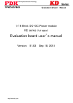
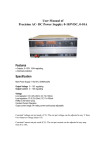
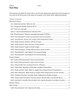
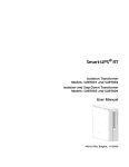
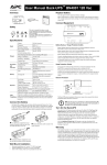
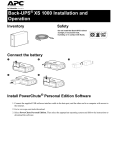
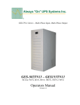
Back-UPS (VA): Back-UPS PRO (VA): STEP 1: 250, 280, 300, 400, 420, 450, 500, 600, 650 650, 1000, 1100, 1400 Connect the UPS’s Internal batteries (Figure 1): NOTE: Battery Disconnect/Connector may vary or be omitted on some models. Figure 1 illustrates some of the variations in connectors. Please follow the illustration which best resembles your UPS. 2 1 Procedure for Figure 1: (1, 2) Remove the two screws holding the battery door. Lay the UPS on its side and open the door 1 Gently pull the battery out. Connect the two wires to the battery 2 NOTE: Make sure to observe the polarity (Red-to-Red, Black-to-Black) NOTE: Small sparks at the battery connections are normal. 1.5 Insert the battery in the UPS. Carefully avoid pinching the wires. 1.6 Close the battery compartment door and replace the screws. 1.1 1.2 1.3 1.4 OR OR A Procedure for Figure 1: (A) 1.1 Locate the ‘Battery Disconnect’ on the rear panel of the UPS. It is typically a Yellow connector. 1.2 If the Battery Disconnect has a metal cover, remove the fastening screws and move the cover A 1.3 Press the yellow connector into the Battery Jack. A snap will be felt as the connector partially engages the jack. A second snap will be felt as the connector securely seats in the Battery Jack. STEP 2: Figure 1 Connect wiring & charge UPS (Figure 2): NOTE: Ensure equipment is turned off. 2.1 Connect equipment to UPS 1 2.2 Connect UPS Power Cord to a suitable power receptacle 2 2.3 Reset the UPS Circuit Breaker by pushing-in the button (Circuit breakers may differ on some models) 3 2.4 Power-up the UPS by pressing the Switch. 2 1 button or 2.5 Wait for the Self-Test to complete, then Power-up equipment. 2.6 Allow UPS to charge batteries for 24 hours prior to operating on battery or performing additional Self-Test or Calibration tests. 1 3 Figure 2 CBM_OTQG_BU3_20110809V02 Page 1 UPS Front Panel (Figure 3): NOTE: Symbols & functions may differ on some UPS models. Figure 4 illustrates some of the variations in displays. Please use the illustration which best resembles your UPS. 1 4 6 3 2 2 7 5 1 Figure 3 ONLINE - UPS is supplying utility power to the POWER ‘ON/OFF’ &/OR TEST BUTTON - 4 Button to turn UPS on or off, or perform a self-test. connected equipment. If not lit, the UPS is not turned ON, or is supplying battery power. ON BATTERY - UPS is supplying battery backup 5 POWER ‘ON/OFF’ SWITCH - Switch to turn UPS 2 on or off. The switch will illuminate when power is present on the output receptacles. OVERLOAD - The power demand from the load has 6 TEST SWITCH - When operating on Utility 3 1 NOTE: Panel Layout may differ depending on model. exceeded the capacity of the UPS. A sustained alarm tone is also emitted. REPLACE BATTERY - UPS fails a self-test, or power, the top part of the switch will cause the UPS to simulate a power outage. ALARM DISABLE SWITCH - When operating on battery, the bottom part of the switch will disable the audible tone. UPS Outlets (Figure 4): power to the connected equipment. UPS will beep four times every 30 seconds. 7 battery is bad. UPS makes short beeps for a minute. BATTERY DISCONNECTED - Flashes to indicate the battery is disconnected. UPS will beep every two seconds. 2 1 1 DB9 Serial Port 2 Site wiring fault Indicator 3 4 UPS input 6 Outlets 7 Battery Disconnect 8 Option Switches 2 6 Modem/Phone/FAX/Network surge protection Circuit breaker/Overload protection 5 8 3 4 3 4 6 7 5 5 Figure 4 Option Switch configuration (Figure 4, reference #8): NOTE: Option switch may not be included on some models. ‘Shutdown Settings’ function is only available on 500 & 650 VA models. Position: UTILITY TRANSFER VOLTAGE Result: Position: AUDIO SETTING Result: (NORMAL SETTING) 103V AC (NORMAL SETTING) AUDIO is enabled. 98V AC AUDIO is disabled. 93V AC 88V AC CBM_OTQG_BU3_20110809V02 Position: SHUTDOWN SETTINGS Result: (NORMAL SETTING) 2 min. prior to shutdown, UPS will sound a tone & activate low battery signal on COM port. Same actions as “NORMAL SETTING”, but delay is increased to 5 minutes instead of 2 minutes. Page 2 UPS troubleshooting: NOTE: Troubleshooting procedures may differ depending on UPS model. Back-UPS troubleshooting Problem: Solution: UPS will not turn on (lamp within power I/O switch is not illuminated), but beeps when power I/O switch is on Line cord plug is loose. Check fitting of line cord plug. Circuit breaker is tripped when button is extended. Unplug excessive loads and reset breaker (press button). Check wall socket with a table lamp. Rear panel circuit breaker is tripped. Dead wall socket. UPS operates normally, but I/O switch not illuminated) Lamp inside the I/O switch is blown. You may continue to use the UPS. It is recommended that the UPS is serviced. The UPS operates normally, but the site wiring fault indicator is lit Building wiring error such as missing ground, hot and neutral polarity reversal, or overloaded neutral wiring. A qualified electrician should be summoned to correct the building wiring. The UPS will not provide rated noise and surge suppression with incorrect building wiring. "Cheater" plug or adapter installed onto line cord plug (ground not connected). Plug the UPS into 2 pole, 3 wire grounding outlet only. UPS occasionally emits a beep, computer equipment operates normally The UPS is briefly transferring your equipment to its alternate power source due to utility voltage sags or spikes. This operation is normal. The UPS is protecting your computer equipment from abnormal utility voltages. If the audible alarm becomes annoying, refer to Option Switch ‘AUDIO SETTING’ section to mute the beeping sound. UPS emits a beep very often, more than once or twice and hour. Computer equipment operates normally Utility voltage is distorted or branch circuits are heavily loaded. Have your line voltage checked by an electrician. Operating your UPS from an outlet which is wired to a different branch fuse or circuit breaker may help. Refer to Option Switch ‘UTILITY TRANSFER VOLTAGE’ section and lower the transfer voltage if it is known that your equipment will operate normally at that voltage. UPS emits loud tone. Power I/O switch is on but computer equipment is not powered. UPS’s rear panel circuit breaker is tripped (button is extended). Normal utility voltages are known to be present UPS has shut down due to severe overload. CBM_OTQG_BU3_20110809V02 Turn off UPS and unplug excessive loads. Laser printers will overload the UPS and should be plugged into a quality surge suppressor. Once overload is removed, reset the circuit breaker (press the button). Page 3 UPS troubleshooting: NOTE: Troubleshooting procedures may differ depending on UPS model. Back-UPS PRO troubleshooting Problem: Solution: UPS will not turn on On/off/test button not pushed. Press the on/off/test button to power the UPS and the loads. Reduce the load on the UPS by unplugging equipment and reset the circuit breaker by pressing the plunger back in. UPS input circuit breaker tripped. UPS will not turn on or off Disconnect the computer interface. If the UPS now works normally, check the interface cable and troubleshoot the attached computer. Computer interface problem. UPS operates on-battery even though line voltage is thought to exist Reduce the load on the UPS by unplugging equipment and reset the circuit breaker by pushing the plunger back in. UPS’s input circuit breaker tripped. UPS beeps occasionally None. The UPS is protecting the load. Normal UPS operation. UPS does not provide expected back up time The UPS’s battery is weak due to recent outage or it is near the end of its service life. The UPS was shutdown by PowerChute® plus software. Charge the battery. The UPS’s batteries require recharging after an extended outage. Batteries age faster when put into service often and when operated at elevated temperatures. If the battery is near the end of its service life, consider replacing the battery even if the replace battery indicator is not yet lit. On-line and overload indicators are flashing alternately None. The UPS will restart automatically when utility power returns. All indicators are flashing OR only the On-line and on-battery indicators are flashing Do not attempt to use the UPS. Turn the UPS off and have it serviced immediately. Internal UPS fault. The UPS operates normally, but the site wiring fault indicator is lit Building wiring error such as missing ground, hot and neutral polarity reversal, or overloaded neutral wiring. The UPS is shutdown and the battery is discharged from an extended power outage. A qualified electrician should be summoned to correct the building wiring. The UPS will not provide rated noise and surge suppression with incorrect building wiring. All indicators are off and the UPS is not operating None. The UPS will return to normal operation when the power is restored and the battery has a sufficient charge. The replace battery light is illuminated Weak batteries. Batteries Disconnect or internal battery lugs not connected properly. The UPS is overloaded. Allow the batteries to recharge for at least 4 hours. If the problem persists after recharging, replace the batteries. Confirm the battery connections and battery Disconnect are firmly installed. The overload light is illuminated or flashing Reduce the load on the UPS by unplugging equipment. For the complete User Manual or comprehensive troubleshooting, please visit the following websites: APC: http://www.apc.com or CBM: http://www.buyupsonline.com CBM_OTQG_BU3_20110809V02 Page 4