1
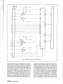
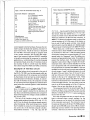
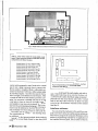
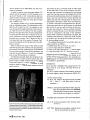
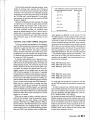
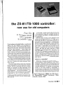
~I••
the ZX-81/TS-1 000 controller:
new use for old computers
'
.
Four ICs
In interface circuit
link compwter
to outside world
If you've been to a ham fest lately, or read the back
pages of any ham magazine, you've probably seen
used Sinclair ZX-81 or Timex/Sinclair 1000 computers
selling for less than $20*. During their heyday several
years ago, these computers - which originally sold
for $150 - led the way for the personal computer revolution. Although the Sinclair was somewhat of a marvel at the time, many users soon became disenchanted
with it, either because of the small membrane keyboard or the difficulty of interfacing it with peripherals.
Perhaps you've stashed a Sinclair away in your junkbox in hope of someday finding something to do with
it. Or perhaps you've toyed with the idea of picking
one up at a hamfest but decided otherwise. Never
mind. Get one.
This small, cheap-looking computer has computing
power comparable to much more expensive computer
systems. The key to harnessing this power is simply
finding an application that takes advantage of its
strengths. For while it's admittedly· disappointing for
· some applications -such as word processing - it's
ideally suited for control functions and can be easily
programmed for a host of controller applications.
*TS-1000 computers ($19.95), manuals ($2.95), and accessories are available from Hai-Tronix, Inc., Dep't HR, P.O. Box 1101, Southgate, Michigan ·
48195 (313-285-1782).
.
In this article, a simple circuit using only four ICs
will be presented, along with a detailed example of
how to program your Z?<-81 or TS-1000 computer for
1/0 applications.
·
With this simple interface circuit attached to the
memory port of either the ZX-81 or TS-1000, you instantly gain the ability to communicate with the outside world. All sorts of applications - including satellite .rotor controls, digital voltmeters, morse code sending and receiving, educational demonstrations, and
many others - easily follow once you have an 1/0
interface. I developed this circuit as part of a school
project a few y~ars ago when I· used the TS-1000
computer to send and receive RTTY. Since then, I've
been selling the information contained herein at cost
to Sinclair computer enthusiasts at local hamfests and
by mail. If you've been wondering how to make your
ZX-81 or TS-1 000 perform some useful tasks and are
interested in a neat one-evening construction project,
then read on.
what is a controller?
While many computers are used for computation,
word processing, or data management, many "small"
computers, composed of just a microprocessor and
a handful of special-purpose chips are built strictly for
controller applications. For example, microprocessor ·
circuitry is now being installed in automobiles. A
microprocessor is programmed with a simple looping
program which does nothing more than continuously
monitor various data lines and then branch to a par-
By Ted. S. Rappaport, N9NB, Box 283, ·Electrical Engineering, Purdue University, West
Lafayette, Indiana 47907.
December 1986
Ull
31
·.
~
1, ·-
FROM SINCLAIR
~E-----o TO
r-18
TO 110
Cl
COMPUTER PORT
ECI
DEVICES
l'JV.
PI
r--
4.7pF
26
+5V
~c
C2
>-'-------
/6A
--j f----a TO 0V
Rli
10
PA7
8
Ul
...
0.01
9_:.14
5
Ro
""\
PA0
15A
IORQ
12
/7A
IJ
WR
II
Ul
36
WI?
7
U'!
TO 0V
...•
P87
/A
27
D7
"'
28
7A
D6
BA
D5
29
lOA
D4
30
D7
D6
D5
9A
D3
3/ D3
D2'
32
5A
D/
33
4A
OliJ
34
1
y
P80
D4
6A
..c.
A
'I
D2
Dl
...
PC7
DO
TO 5V
"
PC4
CJ
·10.0/
~
.,____[E._
78
AliJ
88
AI
;!.28
.A4
2/8
A5
208
A6
/98
A7
._____!j_
3
2
6
5
r-----1
f---J
J
...
0 TO 0V
PC3
~---~
U3
'-.a
6
..::._;-
cs
"
"
PC0
"
v
·•
I(
BAI
~ AliJ
'ro 5V
~
-
GND
4-h.
7
5
7
/08
TO 0V
A3
98
A2
48
ov
..
....__
fig.
1. Schematic diagram for interface circuit.
ticular part of the program when ·specific lines change
state. These input/output (1/0) lines are connected
to hardware such as the fuel level sensor, the climate
control console, and thermal sensors under the hood
and inside the passenger compartment. When the
driver wants to raise the car's interior temperature to
75 degrees, he or she simply presses a button, entering the desired temperature. The program in the microprocessor is continuously looping, searching for any
changes on the input data lines. Finding that the driver has activated the climate control console line, the
32
ril
December 1986
program then branches to the subroutine designed to
effect the desired climate change. In this case, the in.formation (75 degrees) is read into the microprocessor as digital data and a control ~ignal is then sent out
to the appropriate hardware (in this case, the heater
on/off switch). While this is ·an· overly simplified version of what is actually done in today's automobiles,
it illustrates one typical application of a controller.
Qf key importance is the fact that in such applica-tions,· the computer is programmed to handle a variety of input signals from external hardware and issue
"
..;:._,,,,.-.
'
:~rt'.r·-·
'
t
'"
ho·. · - " ·
'
-
....
\ ' -· ..
·
'!.
·
'
•
•' ' . - • • . •
_ ......
.I
•
..
......
• .. -
...... ,
'
~
, • t' •
-
'f ' 'I '•
• .. •
J
• •
-' '"
t
I
'~
- ~
,f
• •: '
'' .J ·, ~--: ,
, • ~
0 ./
,'
! 'I
,
11
.r: '
,
,!,·,(,,,;·,_,,I
•
[
Table 1. Parts list for Interface
Schematic Designator
Circ~it
(fig. 1).
Description
4. 7 ~-tF electrolytic capacitor
0.01 ~-tF capacitor
0.01 ~-tF capacitor
2 row x 23-pin edge connector;
0.1-inch spacing, pin length at
least 0.75-inch.
DB-25 D-connector
74LS32 Quad two-input OR chip
74LSOO Quad two-input NAND
chip
74LS30 Eight-input NAND chip
8255 Programmable Interface
Chip.
C1
C2
C3
EC1
P1
U1
U2
U3
U4
Miscellaneous:
Single-sided circuit board
Jumper wires (at least 10)
Project box (UNIBOXUB270-130)
control signals to external hardware. Because the controller's program is simple and repetitive, it doesn't require much memory. The 2K of memory in the ZX-81
and TS-1 000 is more than enough to program even
a very complex controller. We can also take advantage of the computer's high-level (BASIC) capability
to simplify programming the computer for controller
applications. An understanding of machine lang~age
is important, though, since t~e 1/0 interface must allow exchange of data on a level lower than BASIC;
this is done through the PEEK and POKE commands.
description of interface circuit
With the interface circuit connected to the port of
the ZX-81 or TS-1000, very fast data signals which appear on the data bus of the computer can be latched
by the interface circuit and sent as control signals to
external hardware (1/0 devices). Similarly, in conjunction with the interface circuit, the computer can read
in very fast asynchronous signals from external hard:.
ware and use the received signals to make decisions
in software.
Figure 1 is the schematic diagram of the 1/0 interface. A complete parts list appears in table 1. Note
that no power supply is needed for the interface; all
four ICs are conveniently powered by the computer's
internal 5-volt supply (the voltage is made available at
the computer port).
The heart of the interface circuit is U4, the 8255
programmable peripheral interface (PPI) chip. U 1, U2,
and U3 serve to decode the address signals generated by the computer. After much trial and error, I found
that it's possible to access four 1/0 address locations
not used by any of the internal computer circuitry.
These address locations - 115, 119, 123, and 127
---
-
-
---
-
----
-
--
Table 2. Operation of 8255 PPI chip (U4).
l/0 Instruction 1/0 Address
115
IN
119
IN
123
IN
115
OUT
119
OUT
123
OUT
127
OUT
Operation
Read from Port A
Read from Port B
Read from Port C
Write to Port A
Write to Port B
Write to Port C
Write to Control Register
(decimal) - may be used to activate any .external device connected to the computer port. For my interface circuit, these four address locations are used to
access U4, which in turn directs the flow of data between any external 1/0 device and the computer. In
~able 2, I've shown the addresses used to control the
various registers of. U4. While some of the basics on
how to use U4 will be spelled out later, more details
can be found in any Intel databook or in Goldsbrough's
Microcomputer Interfacing with the 8255.PPI Chip. 2
· When laying out a circuit board, I decided that it
would be nice to have the ability to add components
or connectors in the f~ture. (I call the. upper portion
of the board, where there are several inches of 0.1-inch
spaced holes, the "playground" area.) By adding components and appropriate jumper wires, it's possible to
expand the interface circuit. The single-sided board
negative I used, shown in fig. 2, requires ten insulated jumper wires, which should be installed on the foil
(non-component) side of the circuit board after all of
the components are mounted (see table 3). Pads are
available on the circuit board to permit easy soldering
of each jumper. I used 16 additional jumpers to route
all eight of the port A pins, four of the port B pins,
and four of the port C pins from U4 to molex pins attached on the top of the "playground" area. These
molex pins mate with headers that allow for easy detachment of the data lines from 1/0 hardware or from
a case-mounted connector. You may wish to use just
one pin or all 24 pins available on U4 for 1/0 data exchange. Use as many data lines as you need.
· The component layout for the circuit board (fig. 2)
is shown in fig. 3. When mounting the ICs, be sure
to use a low-wattage·soldering iron since the pads are
delicate. I strongly recommend the use of sockets for
each of the four ICs.
All of the components are easy to acquire at hamfests or electronic shops, except, perhaps, for the
-46-pin connector used to attach the interface board
to the computer memory port. The connector type is
the same as that used on ZX-81 and TS-1000 peripherals such as the 16K RAM-pack, and is a 46-pin, doublesided edge connector with 0.1-inch spacing between
contacts. I found that you have to buy a sturdy con-
----------
December 1986
[II 33
11"'
-· .. , _
0
1:
00000000000000000000000
00000000000000000000000
00000000000000000000000
00000000000000000000000000
00000000000000000000000000
oooooooooooooooooo.oooooooo
00000000000000000000000000
OOOOOOOooooooooooooooooooo
0000000ooooooooooooqooooo~
MD
•
a
D
00000000000000000000000000
D
. .oooooooooooooouoooooooo.o~o
_ _ _ _ _ _ _ _ _ _ _ _. . 0 0 0 0 0 0 0 0
aa
D
a
•
•
~
.. llfHfffau
Of
fig. 2. Single-sided circuit board artwork for 1/0 interface circuit.
Table 3. Jumper wires needed for single-sided circuit
board.The~e connections should be made after all other
components are soldered in place.
Jumper between: U1, pin 11 and U4, pin 36
Jumper between: U2, pin 5 and EC1, pin 198
Jumper between: U2, pin 6 and U3, pin 1
Jumper between: U3, pin 2 and EC1, pin 78
Jumper between: U3, pin 3 and EC1, pin 88
· Jumper between: U3, pin 8 and U4, pin 6
Jumper between: U3, pin 16.and U1, pin 16
Jumper between: U4, pin8and EC1, pin·108
Jumper between: U4, pin 9 and EC1, pin 98
Jumper between: U4, pin27 and EC1, pin 1A
n~ctor
and be prepared to use a Dremel tool or a small
s9w to cut a larger connector down to correct size.
But be carefl!l: I bought a 60-pin, double-sided connector for less than $1.00 fro111 a military surplus dealer
at a hamfest: Eagerly, I took the new connector home,
cu.t.it to length, and soldered it onto the board. After .
a couple of trial fits on the memory port of the computer, the connector crumbled into tiny .bits! It was.
a real pain to have to chop off the faulty connector
and resold~r a new one onto the board! You may notice from the accompanying photographs that the connector must be soldered on the foil side of the board,
and protrudes from th,at side of the board as well.
The entire cost of components is well. under $20.
The construction time is fast - Ofle. evening should
be suffici~nt.
I was able to find attractive plastic boxes made by
UNIBOX3 at a local Radio Shack for less than $4.00
34
rim
December 1986
GOB
C2
C3
D.
GI
U4
~
Cl
,---------~--.+~
L ___ ....:._~'------J
fig. 3. Component layout for interface circuit- view from
component side (I;C1 ~ounted on FOIL s.IDE).
'i
each. The circuit board fits neatly inside·~ and only tyvo
rectangular holes hav~ to be cut into the box: a 0.5
x 2.5-inch hole to allow the 46-pin edg~ connector to
protrude from the circuit board, and a 0.5 x 1.0-inch
hole on the other side of the box to allow. II 0 wires
to be fed to aD-connector mounted on the exterior
(see fig. 4).
interface software
Y <;>U can add all the hardware in the world to a computer, but it won't serve any useful purpose unless you
know how to program the computer effectively. In this
section a programming example for an application of
the interface ~ircuit is given, and a review of how to
. ··---·--------·----------.--~~--"----'-->'---'"----~~~·:..,..~.~-'.c ..
LJ-. ... o.o
'I·
,, ~ !
use the ZX-81 and TS-1000 PEEK and POKE commands is presented.
In order to perform data exchanges between 1/0
devices and the computer, it's first necessary to set
up the 1/0 format on U4. U4 has 24 pins which are
usable for data exchange. These pins are partitioned
into three groups of eight pins. Each group of eight
pins is called a port.
Any program written for 1/0 control should begin
with an initialization stage. This initialization sets the
data flow of the ports on U4. For example, you may
want to program the eight data lines of port A for output (data sent to the 1/0 device from the computer)
and have the eight data lines of port 8 programmed
for input (data sent from the 1/0 device to the computer). While ports A and 8 require that all eight pins
be either input or output, Port C allows for four pins
to be input and four to be output. Of course, Port C ·
may also be programmed for all eight pins to be either
i.nput or output.
While it's beyond the scope of this article to teach
assembly language and machine code programming,
let me assure you that mastering them is not difficult.
If you find the example in this article insufficient, you
may wish to read Chapters 1, 2, and 5 in Hordeski's
easy-to-read Microprocessor Cookbook. 5
The following example details the simplicity of controller software. Consider an alarm system that monitors the status of eight windows around the house.
Three wires (ground, + 5 volts, and data status line)
could be routed to each of eight windows. A small
switch could be mounted by each window so that if
"
'o ,,•. '·" J,, •
.0 " ' 0 o'
~ o ,· ,. o •
o,..o'•o• ·, o _, " " ' .
the window is shut, a low-logic level (0 volts) exists
on the status line. If any of the windows are open,
we want the computer to recognize this and sound
a bell. For this case, we may use all eight pins of Port
A for input (to read the status of each of the eight windows), and may use Port 8 for output (although we
need to use only one of the eight pins to output a control signal for the alarm). Since we're not using Port
C, we don't care what it's programmed for! By connecting the status line of each window to individual
pins of Port A, we can read the status of each window into the computer. If we use a simple transistor
switch to activate the bell, one of the pins from Port
8 can be connected to the gate of the transistor
·switch. When a window is discovered to be open, the
computer then sends out a high-logic level (5 volts)
to the alarm pin (as well as the unused pins) on Port
8, thus sounding the bell.
· The programming steps for the window alarm example would be as follows:.
1. Initialize data flow on Ports A, 8, and C.
2. Look at input data from windows.
3. If any of the input data bits is "1," sound alarm.
4. If the input data is all "0," then go to step 2.
Notice that once the data flow is initialized on U4, no
further action is required unless the power is unplugged or U4 is reprogrammed. The assembly language program for this example follows (comments
are included in parenthesis):
(Initialization):
LD A, 144 (144 = 10010000. This programs Port A for
input, Ports 8, C for output. We load 144 into accumulator.)
OUT 127,A (Send contents of accumulator 144 to the
U4 control register, which is located at ADDR 127.)
(Monitor window data):
loop IN A, 115. (Read in the eight-bit data at ADDR
115 - Port A cumulator.)
and place data in the ac-
· J RZ, loop (Compare the eight bits of data in accumulator to the all-zeros data word 00000000;
if all eight bits of data are zeros, then jump
back to loop and continue to monitor.)
(If program gets to this point, then sound the alarm!):
fig. 4. The circuit board fits into the project box. Be sure to use
an edge connector with at least %"of pin length to allow clearance when the circuit is plugged into the computer port. It is
convenient to have a connector on the back of the box for easy
access to the 1/0 lines.
38
r/1
December 1986
LD A, 255 (Load accumulator with all-ones word,
11111111)
OUT 119, A (Send the accumulator contents out to
Port B; this sounds the alarm).
J UL
••.••
o ooo ••o
••H
j
[' ~;''?"';',
<~"""'
""' • · "'""' ·'"'"' ,,, •·• "' • "., • • '"'" •·" "' • <
" ' co , , '"'"''•' <•, ,, •
<•:",, ,.
< •'• L
"•.- 'M<•" > "• >'. > U.,-,
>.> ,.,_.,,.,_ • .,<,. "··'. "'· ·. " , • • ·· <••
·•·<·.•
<•
i
I
I
The preceding assembly language program, when
written in machine code, requires only 13 bytes of
memory! It's entered into the computer via the POKE
. command. The conversion from assembly language
mnemonics to machine opcodes is given in the ZX-81
and TS-1000 user's manual'appendix. For the previous progrart:l, the machine code that would be POKEd
is given in table 4.
Although not illustrated in this example, it's simple
to monitor your 1/0 activity by going back and forth
between BASIC and machine code. In this case, it
would have been easy to see on the computer monitor which particular window (pr windows) were
opened by simply passing the Port A data to the b-e
register pair in the machine code program, and then
by returning to BASIC by way of the USR command
and printing the value of the USR function on the
screen.
machine code within BASIC programs
To store a machine code program in the computer,
you must first set aside some memory by using a REM
statement (usually the first line in your BASIC program). The REM statement sets aside successive
memory locations which are never written over, thereby allowing you to store machine code programs safely. Machine code programming may be ·saved on tape
by using the SAVE command.
A machine code program is run in sequence by using the USR command, where the argument of the
USR command is the address location of the first machine language opcode. T~e computer returns to the
BASIC program once the return opcode (201) is encountered, and assigns the decimal value of the b-e
register contents to the variable name to which the
USR function is equated. In this manner, it's possible
to pass data from machine code programs (and consequently data from external 1/0 devices) to BASIC.
Or you may use the PEEK command in a BASIC program to retrieve data from dedicated memory locations
in your machine code storage area (REM statement).
Either way, it's a simple chore to t·ransfer data from
''real world" devices to your computer. By using the
POKE command in a BASIC program, you may place
data from BASIC into data locations of machine code
programs. Note that this allows you to make keyboard
entries and have these entries correspond to control
signals for 1/0 devices.
When you're ready to enter a machine·code pro.;.
gram into the computer, clear the computer's memory and begin as if you were writing a new BASIC
program. Enter line 1 as a REM statement, filling in
as many letters in the REM statement as the number
of bytes required in your machine program. It doesn't
matter what you put in your REM statement, because
after you POKE in your machine code, the REM state-
Table 4. Machine code for programming example.
Assembly language instruction
Machine code
LD A, 144
62
144
211
OUT 127, A
127
INA,115
219
115
JRZ~ -4
40
252
62
LD A, 255
255
211
OUT119,A.
119
201
RETURN TO BASIC
ment appears as gibberish on the screen. For the
TS-1000 computer, the first usable memory slot once
a REM statement is entered is 16514. Use the POKE
command to plac~ the machine code in sequential
memory locations starting with 16514. Upon completing the entry of your machine code, place the opcode
201 in the very next memory location following your
last program opcode. At this point it's a good idea to
· save your program on tape (even though it's only a
single REM statement). That way if anything happens
- for example, if junior unplugs your computer - you
don't have to re-POKE your entire program! For the
machine code in table 4, the following would be entered into the computer:
POKE 16514,62 (press enter)
POKE 16515,144 (press enter)
POKE 16516,211 (press enter)
f'OKE 16524,211 (press enter)
POKE 16525,119 (press enter)
POKE 16526,201 (press enter)
To verify that the opcode~ are in memory, you may
use the PEEK command to see what the computer has
stored.
. In order to execute your machine code, you must
have a BASIC statement that contains the USR function. For the window alarm program, your next program line (following the REM statement) could be:
2 LET WINDALARM = USR (16514)
By running this simple two-fine BASIC program, your
Sinclair computer executes the machine code and is
able to communicate with external devices through the
use of the interface circuit! If the machine code was
written so that the Port A data was placed in the b-e
register pair, then the value of the variable WINDALARM, which can be viewed on the monitor with
a simple print statement such as
December 1986
Ul
39
< " ' " •·,
RECEIVE
THIS LCD
CALENDAR!
CLOCK FREE
WITH YOUR
SUBSCRIPTION
WHAT'S REALLY
HAPPENING
IN HOME
SATELLITE
TV?
THE HOME
SATELLITE
TELEVISION
MAGAZINErM
3 PRINT WINDALARM,
could be displayed to indicate (in decimal) the window status.
When using the Sinclair computer as a controller,
more than one machine language program can be
used. It's often convenient to write several subroutines
in machine code, and store them all in succession in
the first REM statement. (Remember they're separate
to the computer when they end in the opcode 201 ).
In this manner, your BASIC program can consist of
various calls to the subroutines by using USR functions with the appropriate memory addresses in the
REM storage.
.conclusion
A monthly of 100-plus pages-has everything you
need to know about where to find equipment, how to
install it, system performance, legal viewpoints, and industry insights! With your subscription to STV®you will
receive a FREE LCD Calendar/Clock.
• Only $19.95 per year (12 monthly issues)
• $1.00 for sample copy
IF YOU HAVE
A SATELLITE
SYSTEM, THEN
YOU REALLY
NEED ...
In this article I've discussed the hardware and software needed to provide a communication path between your Sinclair ZX-81 or Timex/Sinclair 1000
computer and any 1/0 device you might wish to control or monitor. With the price of these computers so
low, even those with the tightest budgets can afford
to experiment with computer control! By now, you
may already have an idea for a controller application
in your shack. If you take an evening out to build this
circuit and spend a few hours reviewing machine language programming, you'll be amazed at what your
small but mighty computer can do!
references
1. Intel is a trademark of Intel Corporation. Information on Intel products may·
be obtained from Literature Department, Intel Corporation, 3065 Bowers
Avenue, Santa Clara,. California 95051.
2. P.F. Goldsbrough, Microcomputer Interfacing with The 8255 PPI Chip,
.Howard W. Sams, Publisher, 1979.
3. UNIBOX, Amerex Corporation, Riverside, California 92502.
4. Michael Hordeski, Microprocessor Cookbook, Tab Books, 1979,
ham radio
The best in satellite programming! Featuring: *All
Scheduled Channels *Weekly Updated Listings
*Magazine Format- *Complete Movie Listing *All
Sports Specials *Prime Time Highlights *Specials
Listing and *Programming Updates!
• Only $45.00 per year (52 weekly issues)
• 2 Years $79.00 (104 weekly issues)
• $1.00 for sample copy
Visa® and MasterCard® accepted (subscription orders only). All prices in US funds·. Write
for foreign rates·.
Send this ad along with your order to:
, STV®/QnSat®
SUBSCRIPTION CALLS ONL V
TOLL FREE 1-800-438-2020
1986
THE 1987
ARRL HANDBOOK
The latest edition of the Ham's bible has been updated with plenty of exciting new projects, new theory
and information chapters and the latest in state-ofthe-art technology. Check out these new features:
Passive LC filter design Including standard value
capacitor tables, overview of 23cm FM fast scan tv
weather satellites basics, a complete revision of the
radio frequencies and transmission section (chapter
22) and satellite communications section (chapter
23). Some of the exciting new projects are: a new hf
legal limit, all band amplifier using the 8877 tube, a
dedicated CRT for Wefax image display and a new
marker generator project for general use to name just
a select few. Over 200 pages have been revised and
updated. Great reference book that should be in every _Ham's shack. Order your's today! Over 1100
pages. @1986. ORDER
I IAR-HB87
!av~~!!-,~o~c~!berJ
P.O. Box 2384-Dept. HR • Shelby, NC 28151-2384
40 fl1 December
AVAILABLE NOW
v
YOURS
NOW
Softbound $17.95
Hardbound $26.95
Please enclose $3.50 shipping & handling.
- 1-------------------1
202
ham-
·
raliiDm~··-'UUI. BOOKSTORE
Greenville, NH 03048