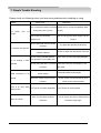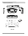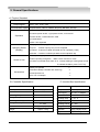
1
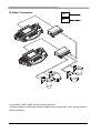
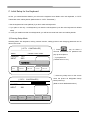
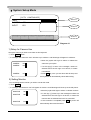
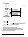
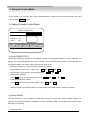
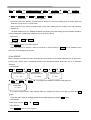
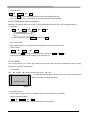
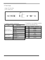
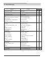
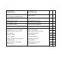
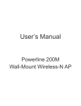
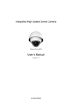
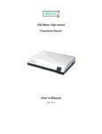
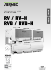
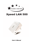
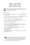
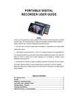
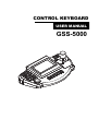
CONTROL KEYBOARD
USER MANUAL
GSS-5000
Caution before installation
Thank you very much for having Green keyboard. You are strongly required to study this
manual before installation. Facing problem or something you don’t understand while
using, please consult with your systems installers or service personnel.
Caution before Installation.
Install the unit after you read following advice.
Avoid installing in places as below,
□ Places with too much high or low temperatures
z Extreme temperatures will damage the unit.
z Always use it within the recommended temperature range of 0℃ to 40℃
□ Where there are excessive dust, smoke, moisture or humidity.
z Using this appliance under such conditions may result in fire, electrical
shock or other serious damage
□ Where the unit can be blended with all kinds of oil or gas
z It may cause the problem if you expose in those conditions.
□ Places with vibration or impact
z Excessive shock may damage the appliance
□ Do not place the appliance in direct sunlight
z It may discolor the unit or cause a problem.
□ Places with high frequency waves, power cables
z Using the appliance under conditions such as electromagnetic waves
cause a problem.
Caution in use
Install the unit after you read following advice.
Avoid following acts,
□ Do not try to disassemble the appliance or put any foreign element.
z It may cause a problem.
□ Turn the power off before installation.
z Before you install the unit, please check the power voltage and turn the
switch on.
□ Never have the unit impacted or operated.
z If you expose the unit to the strong impact or if the button or terminal are
forced to operate, it will be damaged.
(Be careful in using the joystick in particular, if you put too much power on it
while moving left, right or zoom, it may be damaged)
This product has been designed and manufactured in accordance with the harmonized
European standards, following the provisions of the below stated directives.
Electromagnetic Compatibility Directive 89/336/EEC(EN61000-3-2:1995, EN61000-3-3:1995,
EN50081-1:1992, EN50082-1:1997)
This devise complies with part 15 of the fcc rules operation is subject to the following two
conditions: (1) This device may not cause harmful interference and (2) This device must
accept any interference received including interference that may cause undesired operation
• Contents
Caution Before Installation
-----------------
1.
Features & Distinctions
-----------------
2
2.
Basic Setup of Function
-----------------
6
3.
System Setup Mode
-----------------
9
4.
Setup at Control Mode
-----------------
12
5.
Other Detailed Functions
-----------------
16
6.
More Cautions and Check Points
-----------------
19
7.
Simple Trouble Shooting
-----------------
20
8.
Appearance and Dimension
-----------------
21
9.
General Specifications
-----------------
22
Quick Reference
-----------------
24
10.
1. Features & Distinctions
A. COMPONENTS
1) Body of the Keyboard : 1 PC
2) Data Box (Junction Box) : 1 PC
3) Connector Cable (Modular jack) : 1 EA
4) User Manual : 1 EA
2
B. Summary & Features
1) Summary
This unit is a multiple CCTV control keyboard enables to control Speed Dome Camera, CCTV
Receiver, Matrix System, DVR, Quad and so on. You can set up a variety of functions of the
speed dome camera and make efficient use of the dome camera for better surveillance by
gearing all kinds of sensors.
This appliance can be used as a Matrix main(sub) keyboard, CCTV Transmitter main(sub)
keyboard at user’s option.
This manual is explaining only about controlling CCTV Transmitter, please refer to the matrix
manual for the detailed use of Matrix system.
2) Features
• Locking monitor and camera control.
• Convenient control by 5.5 Inch Touch Screen
• Controls up to 512 cameras.
• Controls maximum 32 monitors (when connecting with matrix, GMX-25632)
• Pan/ Tilt/ Zoom controlled by 3-axis joystick.
• Max. 500 Preset widens the surveillance area.
• PAN/ TILT Swing (Auto Pan)
• 12 Group-Tour
• Set and Run the Tour
• Set and Run PTZ Trace.
• Set up on OSD menu of the camera.
• Set and Run Spiral.
• Gearing with alarm receiver unit(controls 512 Sensors)
• Controls DVR with Jog-shuttle (Soon be developed)
• Remote control from Remote Controller
• Users with password only can set up the function.
3
C. Keyboard Functional Keys
12
13
5
2
1
4
3
6
7
11
10
15
9
8
14
1), 2) F/N, F/F: controls focus while using Zoom lens
3) Numeric keypad: used to input numerical value or other functions
4) CLR(CLEAR): used to input number.
5) ENT(ENTER): press this key to input command or save, run designated commands.
6) SET : used to set up Matrix or enter keyboard user setup mode
7) MENU : as a functional key .
8) ALARM: activate or release the alarm when gearing dome camera with ARU (alarm receiver
unit)
9) STATUS : used to enter camera & matrix setup menu.
10) MON: selects monitor.
11) CAM : selects camera
12) Joystick: helps you control the camera up/ down, left/ right, zoom in/ out
13) Touch Screen: support setup button of each function
14) Sensor: allows to remotely control keyboard with remote controller (soon be released)
15) Jog-shuttle: controls DVR(to be released).
4
D. Data Box (Junction box)
Set the communication mode to either RS-485 or RS-422 at your option.
When communicating in RS-485, the switch(485/422) at
both sides should be moved to RS-485.
(It is set to RS-485 when we take from warehouse)
485+ 485- NC
NC
485+ 485- N C N C
GND
GND
422 422 422 422
OUT OUT- IN+
422
IN-
422 422 422
OUT+ OUT- IN+
CAMERA CONTROL 1
RX
485+ 485- N C N C
IN-
CAMERA CONTROL 2
RX
접지
GND
RTS RTS
422 422 422 422
OUT OUT- IN+
IN-
SUB KEYBOARD
INPUT/OUTPUT TERMINAL OF DATA JUNCTION BOX
Camera controls 1: This is the terminal that you can connect with up to 128 speed dome cameras
or receivers.
(Choose either 485 or 422 communication mode and connect in parallel)
Camera controls 2: this is the terminal that you can connect with up to 128 speed dome cameras
or receivers.
(Choose either 485 or 422 communication mode and connect in parallel)
(All together, 256 cameras can be controlled as above connection)
Sub keyboard : This is the terminal that you can connect sub-keyboard with when hoping to use
sub-keyboard and it does duplex transmission.
(Parallel connection is available when using RS485, but if you use RS422 only 1:1
connection is available.)
5
2. Basic Setup of Function
A. Menu Tree
1) SYSTEM SETUP MODE
SYSTEM SETUP MODE
S-CAM
S-MON
S-KEY
PROT-
PASS-
PST
SWING
GROUP
TOUR
TRACE
C/P
L/P
AUX
HOLD
VIEW
QUAD CONTROL MODE
SET
DIVI
RUN
HOLD
VIEW
DVR CONTROL MODE
SET
DIVI
FULL
SEQU
SCR
2) CCTV CONTROL MODE
CAMERA CONTROL MODE
6
B. Basic Connection
485+:
485-:
3 lines (485+, 485-, GND) can be used for data line.
(Ground could be of help when earth is stable, but normally 485+, 485- can be used for
data connection)
7
C. Initial Setup for the Keyboard.
At first, you should decide whether you will use the keyboard as a Matrix main/ sub-keyboard, or CCTV
Transmitter main/ sub-keyboard. (default value is “CCTV Transmitter”)
• Use the keyboard as it was (default) if you don’t need sub-keyboards.
• If you plan to use only 1 sub-keyboard, just reset the sub-keyboard. (use the main keyboard wit default
value)
• In case you install more than 2 sub-keyboards, you will have to reset both main and sub-keyboards
1) Entering Setup Mode
Selecting Main/ Sub Keyboard, locking camera/ monitor, setting protocol and changing password can be
done in this mode.
[ CCTV
CONTROLLER ]
① Press
----------------------------------------<Main>
CAMERA
INPUT
SET
key for about 3
seconds and window for password will
Camera Control mode!
pop up as left picture.
:001
:000
② Input password.
( Default value is 1111)
PASSWORD :
PST
SWING
GROUP
TOUR
COMM OOOOOOOOOOOOOOOOOO
TRACE
ALARM OFF
③ Select any setup menu on the screen
[ CCTV
<Main>
CAMERA
INPUT
S-CAM
when the picture as left(System Setup
CONTROLLER ]
Mode) shows up,
System Setup Mode!
(Refer to each detailed directions.)
:001
:001
S-MON
S-KEY
PROT-
COMM OOOOOOOOOOOOOOOOOOOOO
PASS
ALARM
8
3. System Setup Mode
[ CCTV
CONTROLLER ]
<Main>
Window 1
System Setup Mode!
CAMERA
INPUT
:001
:001
S-CAM
S-MON
Window 2
S-KEY
PROT-
COMM OOOOOOOOOOOOOOOOOOOOO
Window 3
PASS-
ALARM OFF
Diagram 4-1
1) Setup for Camera Use
Set up the camera you wish to use here on this keyboard.
① Touch S-CAM button.
② A message “Set Camera to use!” will show up in window 1 and followings will appear in window 2.
• Move the joystick left/ right to select or release the
CAMERA
:001√
CAMERA
:001√
camera at your option.
• If a tick sign(√) is seen in the rectangle, camera is
.
selected and if the tick sign is not shown, it means
.
not selected.
CAMERA
:512..
• Press SET key once you are done with all setup and
the keyboard will automatically reboot after saving.
2) Setting Monitor
You can designate the monitor you wish to use at this mode.
① Touch S-MON
② A message “Set Monitor to use!” will appear in window 1 and followings will show up at the left picture.
MONITOR
:001√
MONITOR
:001√
.
• If a tick sign (√) shows up in the rectangle monitors are
selected and if the tick sign is not shown, it means the
monitors are not selected and can’t be controlled.
.
MONITOR
• Move the joystick left/ right to select or release monitors.
:512..
• If the correction is completed press SET key and it will
automatically reboot and be saved.
9
3) Setting Keyboard
You can set the keyboard as you like in accordance with its usage.
① Touch S-KEY
② A message “Set Keyboard to use!” will appear in window 1 and classifications will show up as below,
1. CONTROL KEY
[ONLY CAMERA]
[MATRIX USE]
Controls cameras directly (For TX use only)
Controls cameras through Matrix
2. MAIN/ SUB SEL
[MAIN KEY]
[SUB KEY: 01]
….
Set as a Matrix main keyboard, TX
In case you wish to use as a sub-keyboard.
Each sub-keyboard has its own number (up
[SUB KEY: 08]
to 8 sub-keyboard can be used)
3. ALARM TYPE
[ARU ALARM]
[CAM ALARM]
Using Alarm Receiver Unit (ARU)
Using Camera Alarm
③ Setup the keyboard by moving joystick left/ right, up/ down.
④ If the correction is completed do not forget to press “SET” key to save and reboot.
⑤ Setting as a sub-keyboard
Press “SET” key when the keyboard is set as a Main in 2.MAIN/ SUB SEL and window as left will be seen
SUBKEY
:001√
SUBKEY
:002√
Here you will be asked the number of sub-keyboards connecting
with main keyboard.
.
Put the √ sign if the keyboard is connected and press SET key
.
SUBKEY
in the window 2 of Diagram 4-1.
:008..
at the last minute to save and reboot.
Default value is “SUBKEY :001√“
※ Caution
• If you set wrong, turn off the power and try again from the beginning.
• If you once set up the value, it does not change permanently regardless of the power on/ off.
• When setting up several sub-keyboards be careful not to overlap the number of the sub-keyboard.
• If there are any sub-keyboards overlapped, it will not work.
10
4) How to Set Protocol
You will learn how to set protocol here.
① Touch PROT key with your finger.
② A message, Set protocol to use! will be shown in window 1 and following message will appear in window 2
1. PROTOCOL
• Move the joystick left/ right to choose a
protocol at No.1
2. COMM SPEED
( 9600, N, 8, 1 )
(Supports PELCO, SAMSUNG)
• Make a choice for a protocol and pick up a
baud rate.
(Supports 2400, 4800, 9600bps)
• Press the SET key after the correction and the
value would be automatically saved and
reboot.
5). Password Setup
You can create or change the password here. Default value is 1111.
① Touch PASS button.
② A message “Set password to use!” will appear in window 1 and followings will show up in window 2.
1. PASSWORD
OLD :
NEW :
MORE :
• OLD : Input previous PASSWORD
• NEW : Input new PASSWORD
• MORE : Confirm the new PASSWORD again
• Once you are done with correction press SET
key, then it will automatically save and reboot
11
4. Setup at Control Mode
In this chapter, you may learn the usage of detailed setup for Camera, DVR, Quad and launch into each
mode by using STATUS button.
A. Setting Camera Control Mode
[CCTV CONTROLLER]
<Main>
CAMERA
Camera Control mode!
:001
MONITOR :001
INPUT
PST
:000
SWING
GROUP
COMM OOOOOOOOOOOOO
TOUR
TRACE
ALARM OFF
1) Set up PRESET(PST)
This function allows the camera to automatically move to the designated positions and the keyboard can
program up to 500 preset positions for each camera. The memorized preset position can be replaced with
new preset position (new value). Follow the steps as below to set.
① Move the camera to you wish to have the camera memorized.
¨ 1~500 ¨ PST
③ Run PRESET : press preset number programmed
1~500 ¨ PST
② Input PRESET position (1에서 500번까지)
SET
④ Deleting each PRESET
Press CLR key till you hear beep (3secs.) and
1~500
¨ PST
¨ ENT
⑤ Deleting all PRESET positions
Press CLR button till you hear beep (3secs.) and
PST
¨ ENT
※ Maximum number of PRESET positions can be subject to the features of the camera or receiver.
2) Setting SWING
You may select only 2 preset positions memorized from what you had set at preset mode(in horizontal or
vertical) and exercise surveillance repeatedly over the memorized areas. The keyboard can program either
Pan Swing or Tilt Swing.
① Set Swing mode
12
SET
¨ SWING ¨
1 (PAN) / 2 (TILT)
¨ ENT ¨
(either 1 or 2 should be selected)
¨ ENT ¨ 1 ~ 127
¨ ENT ¨
(dwell time)
1 ~ 64
1 ~ 256
¨
(starting preset No.)
ENT
¨
1 ~ 256
(ending preset No.)
¨ SET
(moving speed)
※ Dwell time means the time the camera stays for before it moves from starting point to ending point and
dwell time can be set for 1~127seconds.
※ Moving speed is the camera’s speed which moves from starting point to ending point and maximum
speed is 64.
※ 1 for PAN SWING 2 for TILT SWING should be set. Starting point and ending point for PRESET should be
in horizontal (Pan), vertical (Tilt). Otherwise it may not work properly.
② Run Swing
1 (Pan)
or
2 (Tilt) ¨ SWING
③ Stop Swing
Press SWING button or touch the joystick.
※ When this function is used as a Auto Pan function on CCTV Receiver, SWING can be pressed to stop
and it can not be stopped with joystick.
3) Set GROUP
This is a sequent surveillance function using preset points. Maximum 12 PRESET POINTS can be bound for
1 Group and it allows user to repeatedly observe with designated speed, dwell time. Up to 12 GROUPs
available.
① Set GROUP
SET
¨ GROUP ¨ 1~12 ¨ ENT ¨ 1~256 ¨ ENT ¨ 1~64
Input GROUP No.
Input PRESET No.
(1 ~ 12)
Moving speed
(1 ~ 256)
¨ ENT ¨ 1~127 ¨ ENT
(1 ~ 64)
¨ Input again from PRESET number to keep going on.
Dwell Time
(1 ~ 127)
※ If you wish to input preset in other GROUP after you complete one Group, do it after you finish with SET
button.
※ If you are done with all settings go back to normal mode by pressing SET button.
② Run GROUP
Press Group number 1~12
¨ GROUP
③ Stop GROUP
Press GROUP button or touch joystick.
13
④ Clear GROUP
CLR
¨
¨
GROUP
ENT
※ Hold the CLR key till you hear beep (3secs.) and press GROUP, ENT key..
Each Group (1~6) can not be deleted, all of them should be deleted together.
4) Set TOUR (Auto-Tour Surveillance)
Maximum 12 GROUP can be bound into 1 TOUR sequence that is Auto-Tour with memorized Groups.
① Set TOUR
¨
SET
¨
TOUR
1~12
¨
ENT
¨
Enter a Group No.(1~12)
To add more Groups, enter GROUP number and ENT
② Run / Stop TOUR
Press TOUR button to run, press TOUR button again or touch the joystick to stop.
③ Clear TOUR
¨
CLR
¨
TOUR
ENT
※ Hold down the CLR key till you hear beep (3secs.) and press TOUR and ENT key.
※ Please note that Group will be cleared if you clear the Tour..
5) Set TRACE
This function allows you to track (play back) the movement the user had operated with panning, titling,
zooming for more than 180seconds.
① Set TRACE
SET ¨ TRACE ¨ Moving Joystick with P/T/Z ¨
SET
※ The procedure percentage will show up on the monitor as left picture
while the camera moves (during setup)
Set trace 0~100%
Monitor
② Run/ Stop TRACE
Touch TRACE on the screen to run TRACE and just touch joystick to stop TRACE.
③ Clear memorized TRACE
CLR
¨
TRACE
¨
ENT
* Please study camera manual for more details about Trace function.
14
6) Turning ON/OFF the Camera, Light Power
Select a receiver (camera) you wish to ON/OFF
¨
1~128
① Camera Power
¨
C/P
¨
ON
or
OFF
② Light Power
¨
L/P
¨
ON
or
OFF
② AUX1, AUX2 Power
¨ AUX ¨
ON
or
CAM
OFF
※ This function is only subject to CCTV Receiver.
B. Setting Quad Control Mode
SET
QUAD setup mode
DIVI
Divide the video
RUN
Run the videos
HOLD
Stop the running videos
VIEW
View the selected channel
※ Only works together with Quad Controller(GQC-160) and connected with some specific Quads.
C. Setting DVR Control
SET
DVR setup mode
DIVI
Divide the videos
FULL
View the selected image in full
SEQU
Sequence the videos
SCR
Set division or rotation mode
※ Only some specific DVR can be working together.
15
5. Other Detailed Functions
A. Selecting Camera
Press any camera number (1~255) you wish to control and CAM key.
1 ~ 255
CAM
B. Select Joystick
Move the joystick left/ right or on the diagonal.
Z/O
Z/I
C. OSD Setup Mode
1) Entering OSD Menu
It brings in camera own menu and the menu will appear with beep sound on monitor if you input as below.
1
MENU
2) Control OSD Menu
The cursor will be flickering on monitor (waiting for command)
Move the Joystick right/ left, up/ down and put the cursor as desired.
3) Getting out of OSD Menu
1
MENU
Do as above and the menu on the monitor will disappear and the OSD menu will be released..
※ This function can be used in the speed dome camera only.
16
D. Other Setup Mode.
1) Spiral Function
This function is supported only on speed dome cameras, the fixed panning speed and tilting speed are
operated at the same time that can make spiral surveillance.
*CAMERA SPIRAL?
RUN
7
ON
MENU
또는
OFF
Press On/Off
2) Camera Remote Reset
Initialize the camera or receiver in case they have a problem .
1~255
CAM
10
MENU
ENT
*CAMERA REMOTE
RESET?
※ Supported only on Speed Dome Camera.
Press Enter
3) Keyboard Buzzer On/Off
Turn on/ off the buzzer of the keyboard.
200
*Keyboard Buzzer
MENU
On/Off
4) LCD Contrast setting
Adjust the brightness by moving joystick up/ down.
20
*LEVEL: 0020
MENU
17
5) Converting Up/ Down
Convert the control of up/ down, for instance, If you
move the joystick down, it will go up.
*TILT UP/DOWN
CHANGE?
MENU
11
Press Enter
※ This function can be operated only on GRX-502A
6) Converting Left/ Right
Convert the control left/ right, for instance, if you
move the joystick left, it will move right.
*PAN LEFT/RIGHT
CHANGE?
MENU
12
Press Enter
※ This function can be operated only on DRX-502A
7) Convert the voltage of Lens Control
When the movement of Zoom Lens is too slow or fast, you can change the voltage to adjust the proper
speed.
15
MENU
Number Key
(1=6V, 2=9V, 3=12V)
*ZOOM LENS
POWER CHANGE?
Press Numric
ENT
1,2,3 ENT
※ This function can be operated only on GRX-502A.
8) Checking CCTV Receiver Model
Used to check out the camera or CCTV receiver installed outside.
GSC-300
3
Ver 6.0
STATUS
Information such as Model number and manufacturer will show up on
both monitor and screen of keyboard.
Press CLR key to make it disappear.
18
6. More Cautions and Check Points.
Cautions in Use
z
Do not give a power to the unit in the process of installing.
z
It is recommended that the unit be installed in a well-ventilated place since the operating
range is 5°C~40°C.
z
Do not expose the unit to extreme impact, which may cause serious damage.
z
Avoid installing in the direct rays of the sun.
z
Never install the unit in place with strong magnetic, an electric or a radio wave which
cause a problem in communication.
z
Be careful not to connect wrong cable or line while installing.
z
Never operate the unit until the buzz(beep sound) goes off after turning on the power.
z
Give a power to the unit after you check the insulated wire connected outside.
z
Always use the keyboard cable provided with the keyboard.
z
Do not give a too much strength to the joystick while controlling.
19
7. Simple Trouble Shooting
Please check out followings when you face some problems while installing or using.
Problem
Check Point
Reference
Is the connection between keyboard Make sure to connect the Modular cable.
The
power
can’t
be
and junction box correct?
(RJ45)
brought.
Is the Power sources being
Be sure to plug the power supply into the
supplied now?
consent.
Did you press the camera number
correctly?
The camera can’t pan/ tilt.
Is the RX address the same as
Camera address?
Hasn’t the sub-keyboard address
Try again after pressing CLR button.
Check out again the DIP Switch of the RX.
Check setup of main/ sub-keyboard again.
It’s not working in Sub- been repeated as you initially set?
keyboard.
Has the data cable been connected Check the connection and polarity of the
correctly?
data cable.
Have you set Preset positions at
Preset movement is not
working.
There is an error when
setting motion.
Alarm can’t be on..
Preset mode?
Set Preset position and try again.
Does the camera support Preset
Press number 3 and STATUS key and
function?
check out the camera model.
Have you set it on Main keyboard? It can’t be set on Sub-keyboard.
Have you set off the all Alarm
If you set it off it can’t be on. Please refer to
channels?
the Alarm setup page.
20
8. Appearance and Dimensions
21
9. General Specifications
A. Product Standard
Classification
Output Signal
Specification
● RS – 422 ● RS – 485
Communication speed ● Speed 9,600, 4,800, 2,400BPS, No parity, 8Bit data, 1Bit stop
● Control Pan/Tilt /Zoom lens
● Camera power On/Off , Light power On/Off , AUX On/Off
Operation
● Alarm On/Off , Preset set/clear ,OSD
● Control Matrix
● Main / Sub keyboard
● Display : LCD Display ( The way to select Menu )
Operating Status
(Display)
● Input ? : Number input by Key can be outputted.
● Camera : If camera is called input data can be outputted.(1~256)
● Monitor : If monitor is called input data can be outputted1-64)
● When pressing key : Make a buzz sound for about 0.5seconds.
Sound in Use
● When inputting wrong data : Make a buzz sound for 3 times.
● If alarm is sounded when Alarm is on : it keeps making a warning beep sound
To release the Alarm, press “CLR” key.
Accessories
● Body of keyboard
-1-
● Modular cable(RJ-45cable with 10M long)
-1-
● Data junction box
-1-
● DC 12V 1A Adaptor
-1-
B. Controller Specification
C.Junction Box Specification
ITEM
Specification
In/ Output Terminal
Modular jack
Communicate with Junction Box
Item
Specification
In/output terminal Modular jack
TTL
Power supply
DC 12V, 1A Adapter
Operating Temperature
0∼40。C
Camera Control
RS-485/RS-422
Storage Temperature
-5∼55°C
Operating temp.
0∼40。C
Operating Humidity
10∼75%
Storage temp.
-5∼55°C
Storage Humidity
10∼95%
Operating humid. 10∼75%
Dimension
Weight
338(L)×180(W)×45(H)
Approx. 1.2kg
22
Storage humidity
10∼95%
Dimension
109(L)×66(W)×27(H)
Weight
Approx. 0.3kg
D. Power Supply
Voltage : DC 12V (±10%)
Current : 500mA (min)
F. Constitution of pin between controller
and junction box(Modular Jack)
E. CAMERA CONTROL INTERFACE
ITEM
Specification
Pin no.
Controller ↔ Junction box
1 Start bit
1
RX-TXD
8 Data bit
2
B+12V
No parity
3
RX-RXD
1 Stop bit
4
RX-RTS
11 Byte command
5
GND
Mark logic "1"
6
SK-TXD
Space logic "0"
7
SK-RTS
8
SK-RXD
Asynchronous Serial Interface
Synchronization /
System& word length
Signal polarity
Transmit direction
Half duplex
Transmit speed
9600 bps
23
10. Quick Reference
Operation
Function
Function Input
Main
Sub
Keyboard [1-64] + [MON]
Select Monitor
◎
◎
Keyboard [1-512] + [CAM]
Select Camera
◎
◎
Power supply ON + [SET]
Setting Controller
◎
◎
[SET]
Start Setup mode for Preset
◎
◎
◎
◎
◎
◎
◎
◎
[SET]+[Joystick Stop]+[Keypad 1~128]+[PST]
Run Preset, Preset movement
[Preset No]+[PST]
[CLR+3sec]+[Keypad 1~128]+[PST]+[ENT]
Deleting each Preset
[CLR+3sec]+[PST]+[ENT]
Clear all Preset Positions
[SET]+[SWING]
Start Setup mode for Swing
[1/2]+[ENT]
Select Pan or tilt swing
[Keypad1~128]+[ENT]+[Keypad 1~128]+
Select 2 different preset positions
[ENT]
Set Swing Speed
[Keypad 1~127]+[ENT]
Set dwell time
[Keypad 1~64]+[ENT]
Run Pan or tilt swing
[1/2]+[SWING]
Stop Swing
[SET]+[GROUP]
Start setup mode for Group
[Keypad 1~6]+[ENT]
Select Group number
[Keypad 1~64]+[ENT]
Select Preset point
[Keypad 1~64]+[ENT]
Set moving speed between Preset positions
[Keypad 1~127]+[ENT]
Set Dwell time
[SET]
Confirm Input value
[Keypad 1~12]+[GROUP]
Run Group Surveillance
[GROUP]/Joystick
Stop Group Surveillance
[SET]+[TOUR]
Start setup mode fro Tour
[Keypad 1~12]+[ENT]←repeat
Set Tour repeatedly
[SET]
End setup for Tour
[TOUR]
Run Tour Sequent surveillance
[C/P] + [ON/OFF]
Turn on/ off CCTV CAMERA power
◎
◎
[L/P] + [ON/OFF]
Turn on/ off CCTV LIGHT power
◎
◎
24
[7]+[MENU]+[ON]
[7]+[MENU]+[OFF]
[Keypad〕
[1~512]+[CAM]+[10]+[MENU]+[ENT]
Run Spiral function
Stop Spiral function
Camera Reboot
◎
◎
[20]+[MENU]
Brightness Mode of LCD
Joystick up/down +[CLR]
Ending brightness control
[11] + [MENU] + [ENT]
Converting Up / Down Mode
◎
[12] + [MENU] + [ENT]
Converting Left / Right Mode
◎
[15] + [MENU] + [1/2/3] + [ENT]
Converting Lens Voltage, 6V / 9V / 12V
◎
Hold down [CLR] key for 3 seconds
Enter CLEAR MODE
[PRESET Number 1~64] + [PST]
Delete Preset position one by one
◎
[PST] + [ENT]
Clear all Preset postions
◎
[GROUP] + [ENT]
Clear all Group
[TOUR] + [ENT]
Clear Tour Sequence
[Sensor Number 1~255] + [ALARM
Delete Alarm one by one
[ALARM] + [ENT]
◎
◎
◎
◎
◎
◎
Clear all Alarms
◎
◎
[Monitor Number 1~64] + [MON]
Delete Monitor one by one
◎
◎
[[MON] + [ENT]
Clear all Monitors
◎
◎
26
27
DISTRIBUTED BY