1
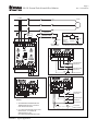
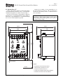
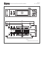
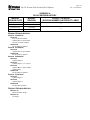
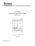
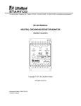
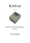
3714 Kinnear Place Saskatoon, SK Canada S7P 0A6 Ph: (306) 373-5505 Fx: (306) 374-2245 www.littelfuse.com/relayscontrols SE-105 MANUAL GROUND-FAULT GROUND-CHECK MONITOR REVISION 13-D-050315 F1 CT1 CT2 GROUND FAULT A B L1 L2 RESET GROUND CHECK GF MODE 4.0 A SH 2.0 A 0.5 A UV POWER 1.0 0.1 2.0 GF TRIP TIME (s) ENHANCED FILTERING SE-105 SW CI GF-GC MONITOR GI GC G F2 Copyright 2015 by Littelfuse Startco All rights reserved. Document Number: PM-1300-EN Printed in Canada. SE-105 Ground-Fault Ground-Check Monitor This page intentionally left blank. Page i Rev. 13-D-050315 Page ii Rev. 13-D-050315 SE-105 Ground-Fault Ground-Check Monitor TABLE OF CONTENTS SECTION LIST OF TABLES PAGE 1 2 General ................................................................. 1 Operation ............................................................. 1 2.1 Settings.................................................................. 1 2.1.1 GF Trip Time ............................................. 1 2.1.2 GF .............................................................. 1 2.1.3 Mode .......................................................... 1 2.2 Indication and Reset .............................................. 1 2.3 Fusing.................................................................... 1 3 Installation ........................................................... 2 3.1 SE-105 .................................................................. 2 3.2 Ground-Fault CT................................................... 4 3.3 Ground-Check Termination .................................. 5 3.4 Remote Operation ................................................. 6 3.5 Parallel-Path Isolation ........................................... 6 3.6 Ground-Fault Testing ............................................ 6 4 Compatibility ....................................................... 6 5 Technical Specifications ................................... 12 5.1 SE-105 ................................................................ 12 5.2 Current Sensors ................................................... 13 5.3 Termination Assemblies ..................................... 13 6 Ordering Information ....................................... 13 7 Warranty ........................................................... 14 8 Ground-Fault Performance Test ..................... 15 Appendix A SE-105 Revision History......................... 16 LIST OF FIGURES FIGURE 1 2 3 4 5 6 7 8 9 10 11 12 13 PAGE Typical Application .............................................. 3 SE-105 Outline and Mounting Details .................. 4 CT200 and CT200L Current Transformers .......... 5 Zener-Diode Termination Devices........................ 6 SE-TA6 Termination Assembly ............................ 7 SE-TA6ASF-WL Small-Format Termination Assembly with Wire Leads ................................... 7 RK-102 Remote Indication and Reset Kit ............ 8 RK-105 Remote Indication-and-Reset Assembly . 8 RK-105I Remote Indication Assembly ................. 9 RK-13 Relay Interface Module ............................. 9 PPI-600V Parallel-Path Isolator .......................... 10 PPI-600V Typical Installation ............................ 11 Ground-Fault-Test Circuits ................................. 15 TABLE 1 2 PAGE Terminal Designations .......................................... 6 Ground-Fault-Test Record .................................. 15 DISCLAIMER Specifications are subject to change without notice. Littelfuse Startco is not liable for contingent or consequential damages, or for expenses sustained as a result of incorrect application, incorrect adjustment, or a malfunction. SE-105 Ground-Fault Ground-Check Monitor This page intentionally left blank. Page iii Rev. 13-D-050315 SE-105 Ground-Fault Ground-Check Monitor 1. GENERAL The SE-105 is a combination ground-fault and groundcheck monitor for resistance-grounded systems in nonhazardous applications. The ground-fault circuit is latching and the ground-check circuit is typically nonlatching. One output contact is provided for contactor control, or for shunt or undervoltage operation in a breaker trip circuit. Ground-fault current is sensed by a CT200-series current transformer. A trip level of 0.5, 2.0, or 4.0 A is switch selectable for use with a 5-, 15-, or 25-A grounding resistor. Enhanced filtering eliminates false ground-fault trips from adjustable-speed-drive harmonic distortion. Trip time is adjustable from 0.1 to 2.0 seconds. The fail-safe ground-check circuit is validated by an end-of-line termination with a 5.6-volt Zener characteristic. The Zener-characteristic clamps induced voltage and allows induced current to flow in the groundcheck loop. Consequently, induced-ac-withstand capability, noise immunity, and open/short detection are independent of current in the phase conductors. Enhanced filtering prevents false ground-check validation due to an active chopper condition. See www.littelfuse.com/relayscontrols for Technical Note GC-1. NOTE: The SE-105 is not a lock-out device. Follow lock-out procedures for maintenance. 2. OPERATION 2.1 SETTINGS 2.1.1 GF TRIP TIME Ground-fault trip time is adjustable from 0.1 to 2.0 seconds. Time-coordinated ground-fault protection requires this setting to be longer than the trip time of downstream ground-fault devices. 2.1.2 GF The ground-fault-circuit trip level is 0.5, 2.0, or 4.0 A when current is sensed with a CT200-series current transformer. Since the ground-fault-circuit trip level should not be greater than 20% of the grounding resistor let-through current, these levels are appropriate for use with 5-, 15-, or 25-A grounding resistors. For other applications, the trip level of the ground-fault circuit is 0.25, 1.0, or 2.0% of the primary rating of the 5-Asecondary current transformer. 2.1.3 MODE In the shunt-trip mode (SH), the output relay energizes and its contact closes if the ground-check loop becomes Page 1 Rev. 13-D-050315 invalid or if a ground-fault trip occurs. The shunt-trip mode is not fail-safe and is not recommended because: Shunt-trip devices do not operate if supply voltage fails. Shunt-trip ground-check circuits allow open cable couplers to be energized for a short interval after supply voltage is applied. In the undervoltage mode (UV), the output relay is energized and its contact is closed when the ground-check loop is valid and the ground-fault circuit is not tripped. The undervoltage mode is referred to as fail-safe and is recommended because: Undervoltage devices release if supply voltage fails. Undervoltage ground-check circuits do not allow cable couplers to be energized until the ground-check loop is verified. For fail-safe-only applications, use an SE-107 GroundFault Ground-Check Monitor. 2.2 INDICATION AND RESET The blue POWER LED indicates that the internal power supply is on. The red GROUND FAULT LED indicates a ground-fault trip and the green GROUND CHECK LED indicates a valid ground-check loop. When a ground-fault trip occurs, the SE-105 remains latched until the reset button is pressed or the supply voltage is cycled. The ground-check circuit is non-latching and does not require a reset. Terminals are provided for remote indication and reset as shown in Fig. 1. For latching ground-check (Option L), the GROUND CHECK LED is red and it indicates a latched ground-check trip. 2.3 FUSING The output contact is protected by fuse F1 (4.0 A, time delay). The ground-check circuit is protected by fuse F2 (0.5 A, time delay). SE-105 Ground-Fault Ground-Check Monitor 3. INSTALLATION 3.1 SE-105 SE-105 outline and mounting details are shown in Fig. 2. Typical connections are shown in Fig. 1. Connect supply voltage to L1 and L2. For a 120-Vac supply, connect supply neutral to L2. For direct-current supply (Option D), connect supply negative to L2. Connect chassis-bonding terminal to ground. Connect contact terminals A and B as required. Faceplate LED's are driven in series with remoteindication LED's. When a remote kit is not used, terminals CI, +, and GI must be connected for the faceplate LED’s to operate. These jumpers are installed at the factory. Connect terminal GC to the outgoing ground-check conductor and connect terminal G to ground. To meet electrical code requirements, do not jumper chassisbonding terminal to terminal G. Install the upper terminal-block cover to prevent inadvertent contact with line terminals. Page 2 Rev. 13-D-050315 Page 3 Rev. 13-D-050315 SE-105 Ground-Fault Ground-Check Monitor CT200 LOAD GROUND UV 120 VAC L GROUND CHECK GC GC N A GROUND FAULT B L1 G RESET GROUND CHECK GF MODE 4.0 A SH 2.0 A 0.5 A UV POWER NOTE 1 ALTERNATE TERMINATION CIRCUIT FOR REMOTE CONTACTOR CONTROL GROUND-CHECK TERMINATION L2 HOLD-IN G CONTACT USE LOWLEVEL CONTACTS NOTE 1 F1 CT1 CT2 START STOP SE-105 GF-GC MONITOR SW CI GI GC G 1.0 0.1 2.0 GF TRIP TIME (s) F2 ENHANCED FILTERING SE-105 GF-GC MONITOR SW CI GI GC GI G RED + F2 CI GROUND-FAULT INDICATOR GROUND-CHECK GREEN INDICATOR SW RESET SWITCH REMOTE INDICATION AND RESET SE-105 SE-105 GF-GC MONITOR SW CI GI GC CI/GI + CI/GI S W R S 1 R S 2 K1 K1 S W R S 1 R S 2 K1 K1 C G I + G R I + F2 GI/RI C G I + G R I K2 K2 NOTE 2 GI K2 K2 G F2 GI/RI TB1 TB1 GI GC G SW SW GF-GC MONITOR SW CI NOTE 2 RK-13 CONNECTION WITHOUT REMOTE INDICATION OR RESET NOTES: 1. SEE ORDERING INFORMATION FOR TERMINATION DEVICES. 5-W AXIAL LEAD DEVICE INCLUDED. 2. K1 CLOSES ON GROUND-CHECK VALID. FOR OPTION L, K1 CLOSES ON GROUND-CHECK TRIP. K2 CLOSES ON GROUND-FAULT TRIP. FIGURE 1. Typical Application. + CI RED GROUND-FAULT INDICATOR GROUND-CHECK GREEN INDICATOR SW RESET SWITCH 24-120 Vac/Vdc ALTERNATE RESET CIRCUIT RK-13 CONNECTION WITH REMOTE INDICATION AND RESET Page 4 Rev. 13-D-050315 SE-105 Ground-Fault Ground-Check Monitor 3.2 GROUND-FAULT CT Outline and mounting details for CT200 and CT200L current transformers are shown in Fig. 3. Pass the phase conductors through the CT window as shown in Fig. 1. Do not pass the ground or ground-check conductors through the CT. In applications that require shields or drain wires to pass through the CT, return them through the CT before connecting them to ground. Connect the secondary of the ground-fault CT to SE-105 terminals CT1 and CT2. The CT connection to the SE-105 is not polarity sensitive. Ground one side of the CT secondary. NOTE: The CT200 and CT200L are 600-V-rated current transformers. When system voltage is above 600 V, ensure conductors passed through the sensor window are insulated to system voltage. NOTE 5 100.0 (3.93) 43.5 (1.71) 109.0 (4.29) 88.9 (3.50) 77.8 (3.06) F1 CT1 CT2 A B L1 L2 GROUND CHECK GF MODE 4.0 A SH 2.0 A 0.5 A UV POWER 1.0 0.1 2.0 GF TRIP TIME (s) (5.90) RESET (5.50) 150.0 GROUND FAULT 139.7 NOTE 4 ENHANCED FILTERING SE-105 SW CI GF-GC MONITOR GI GC G F2 43.5 (1.71) 4.8 (0.19) DIA NOTES: 1. DIMENSIONS IN MILLIMETRES (INCHES). NOTE 5 2. TERMINAL-BLOCK SCREWS: 6-32 x 0.25. 3. MOUNTING SCREWS: M4 OR 8-32. 4. SHOWN WITH TERMINAL-BLOCK COVER REMOVED. 5. MINIMUM CLEARANCE FOR FUSE REMOVAL. FIGURE 2. SE-105 Outline and Mounting Details. Page 5 Rev. 13-D-050315 SE-105 Ground-Fault Ground-Check Monitor 44.5 MAX (1.75) D NOTES: 1. DIMENSIONS IN MILLIMETRES (INCHES). X2 X1 E A 2. MOUNTING SCREWS: M4 OR 8-32. BLACK WHITE B SIDE FRONT B 9.4 (0.37) 44.5 (1.75) F 22.2 (0.87) C TAP M4 OR 8-32 BOTTOM PART NUMBER MOUNTING DETAIL DIMENSIONS A B C D E F CT200 55.9 (2.20) 120.7 (4.75) 101.6 (4.00) 98.3 (3.87) 108.0 (4.25) 5.6 (0.22) CT200L 88.9 (3.50) 154.0 (6.06) 133.4 (5.25) 139.7 (5.50) 144.5 (5.69) 7.1 (0.28) FIGURE 3. CT200 and CT200L Current Transformers. 3.3 GROUND-CHECK TERMINATION Install the ground-check termination at the load to complete the ground-check loop as shown in Fig. 1. Termination outlines and mounting details are shown in Figs. 4, 5, and 6. Use only a Littelfuse Startco termination device; others may not meet performance requirements. Connect terminal G of the termination to the equipment frame so that the ground-conductor-toequipment-frame connection is included in the monitored ground-check loop. Connect terminal GC of the termination to the incoming ground-check conductor. If ground-check interlocks are used, low-level (bifurcated, precious-metal, or sealed-reed) contacts are recommended. If used as a ground-fault monitor only, install the termination at the SE-105. Page 6 Rev. 13-D-050315 SE-105 Ground-Fault Ground-Check Monitor 3.4 REMOTE OPERATION Terminals SW, CI, , and GI are provided for remote LED indication and remote reset as shown in Fig. 1. Remote LED's are driven in series with the front-panel LED's. Remove factory-installed jumpers from terminals CI, +, and GI, and connect a remote kit as shown in Fig. 1. Optional remote kits are shown in Figs. 7, 8, and 9. Standard LED indicator lamps are not compatible with the SE-105. For general-purpose applications, use the RK-105 Remote Indication-and-Reset Assembly or the RK-105I Remote Indication Assembly. Connect terminals SW, CI, +, and GI to remote-kit terminals SW, CI/RI, +, and GI. For 22-mm-component applications, use the RK-102 Remote Indication and Reset Kit. Connect terminal X2 of the green ground-check indicator to CI, terminal X2 of the red ground-fault indicator to GI, and connect indicator X1 terminals to +. For remote reset, connect the normally open push-button switch across terminals + and SW. If indication is required from a separate voltage source, or if separate ground-fault and ground-check contacts are required, use an RK-13 Relay Interface Module. The RK-13 mounts on the SE-105 lower terminal block and is compatible with the RK-102, RK-105 and RK-105I. See Figs. 1 and 10. Contact K1 closes when the GC LED is on and contact K2 closes when the GF LED is on. 3.6 GROUND-FAULT TESTING Use CT-primary current injection to test the groundfault circuit. Fig. 13 shows test circuits using the SE-400 Ground-Fault-Relay Test Unit and the SE-100T GroundFault-Relay Tester. The SE-400 has a programmable output of 0.5 to 9.9 A for a duration of 0.1 to 9.9 seconds. The SE-100T has LO and HI outputs for 5- and 15-A resistance-grounded systems. A test-record form is provided in Section 8 of this manual. Record the test results and test dates on this form to meet the requirements of the National Electrical Code (NEC). Retain the form so that the test data can be made available to the authority having jurisdiction. 4. COMPATIBILITY The SE-105 is a direct replacement for the SEL-100, SEL-100TD, SE-101, SE-101S, SE-102, SE-102S, SE102M, SE-103, and SE-103S. Terminal designations have been changed as shown in Table 1. Terminals CT1 and CT2 are transformer isolated so that the CT secondary can be grounded. Units with old designations do not allow the secondary of the groundfault CT to be grounded when the ground-check circuit is used. TABLE 1. TERMINAL DESIGNATIONS SE-105 OLD DESIGNATION DESIGNATION CT CT (RELAY) (RELAY) L N SW PL + GL P G 3.5 PARALLEL-PATH ISOLATION A PPI-600V can be used for parallel-path rejection. A PPI-600V will also eliminate intermachine arcing and prevent stray ac and dc currents from flowing in the monitored ground wire. See Figs. 11 and 12. See Technical Note GC-10 “Parallel Path Isolator” at www.littelfuse.com/relayscontrols, or contact Littelfuse Startco for application details. 69.9 (2.75) G 35.0 (1.38) 10.0 NOTES: 0.25” - 28 UNF (0.40) TERMINATION MUST BE INSTALLED AT LOAD. 1N5339B 250 (9.84) LENGTH OF # 14 AWG YELLOW STRANDED WIRE G G GC GC SE-TA6-SM FIGURE 4. Zener-Diode Termination Devices. 1. DIMENSIONS IN MILLIMETRES (INCHES). 2. CAN BE IMMERSED IN GLYCOL. CT1 CT2 A B L1 L2 SW CI + GI GC G Page 7 Rev. 13-D-050315 41.5 (1.63) 40.0 (1.57) 22.2 (0.87) 40.0 (1.57) 10.5 (0.41) 19.0 (0.75) 8.0 (0.31) SE-105 Ground-Fault Ground-Check Monitor SE-TA6 TERMINATION ASSEMBLY 51.0 (2.01) 67.0 (2.64) G 67.0 (2.64) TAP M4 OR 8-32 GC 4.5 (0.18) Ø, C’BORE 10.0 (0.39) Ø 3.2 (0.13) DEEP FRONT SIDE MOUNTING DETAIL NOTES: 1. DIMENSIONS IN MILLIMETRES (INCHES). 2. TERMINAL-BLOCK SCREWS: 6-32 x 0.25. 3. MOUNTING SCREWS: M4 OR 8-32. 4. ENCLOSURE IS ELECTRICALLY CONNECTED TO TERMINAL G. 5. CAN BE IMMERSED IN GLYCOL. FIGURE 5. SE-TA6 Termination Assembly. 50.8 (2.00) MOUNTING DETAIL SE-TA6ASF-WL TERMINATION ASSY Serial No: DE130600619 Rev: 01 Rating: 5.6 Vdc @ 105 mA 12 W Max C Use with: SE-134, SE-134C, SB6100 R US LR 53428 12.7 (0.50) 4.0 (0.16) 3.2 (0.13) 12.7 (0.50) NOTE 2 SIDE G 300 (12) OF GREEN/YELLOW WIRE 1. DIMENSIONS IN MILLIMETRES (INCHES). 19.0 (0.75) GC 300 (12) OF YELLOW WIRE NOTES: 58.8 (2.32) 2. MOUNTING SCREWS M3.5 OR 6-32. 3. CAN BE IMMERSED IN GLYCOL. TOP FIGURE 6. SE-TA6ASF-WL Small-Format Termination Assembly with Wire Leads. Page 8 Rev. 13-D-050315 SE-105 Ground-Fault Ground-Check Monitor 30.0 (1.18) 25.0 GROUND FAULT LEGEND PLATE (0.59) NOTE 2 22.5 (0.89) 15.0 43.5 (1.71) GROUND CHECK (0.98) RESET 22.2 (0.87) DIA 17.3 (0.68) 36.6 (1.44) 29.9 (1.17) LEGEND PLATES NOTES: LED PILOT LIGHTS 14.9 (0.59) 30.0 MINIMUM (1.18) 2. ----- INDICATES CLEARANCE REQUIRED. (1.57) 40.0 MINIMUM 43.5 (1.71) 1. DIMENSIONS IN MILLIMETRES (INCHES). 3. PANEL THICKNESS 1.0 TO 6.0 (0.04 TO 0.24). 29.9 (1.17) 36.6 (1.44) 4. NEMA 4X. 5. CERTIFICATIONS NOT SHOWN. MOUNTING DETAIL PUSH BUTTON FIGURE 7. RK-102 Remote Indication and Reset Kit. 30.0 (1.18) 60.0 (0.98) (0.30) 10.0 7.7 (0.40) 25.0 (2.36) 44.5 (1.75) OUTLINE 28.58 (1.125) GROUND CHECK GROUND FAULT 1.25” CONDUIT KNOCKOUT 1.70” DIA 96.0 RESET (3.78) 76.0 (3.00) CI/RI + GI SW RK-105 R 22.25 (0.875) SIDE VIEW FRONT VIEW MOUNTING DETAIL NOTES: 1. DIMENSIONS IN MILLIMETRES (INCHES). 2. NEMA 1. FIGURE 8. RK-105 Remote Indication-and-Reset Assembly. 3.8 (0.15) DIA Page 9 Rev. 13-D-050315 SE-105 Ground-Fault Ground-Check Monitor 30.0 (1.18) 60.0 (2.36) 44.5 (1.75) 7.7 25.0 (0.30) 10.0 (0.40) (0.98) OUTLINE 28.58 (1.125) GROUND CHECK GROUND FAULT 96.0 1.25” CONDUIT KNOCKOUT 1.70” DIA (3.78) 76.0 (3.00) CI/RI + GI SW RK-105I R 22.25 (0.875) SIDE VIEW 3.8 (0.15) DIA MOUNTING DETAIL FRONT VIEW NOTES: 1. DIMENSIONS IN MILLIMETRES (INCHES). 2. NEMA 1. FIGURE 9. RK-105I Remote Indication Assembly. SW + GI/RI 31.0 (1.22) 47.5 (1.87) CI/GI TB1 S W R S 1 R S 2 K1 C G I + C G I + G R I K2 G R I K2 SIDE VIEW RK-13 SHOWN MOUNTED ON SE-105/SE-107/SE-325 60.2 (2.37) R S 1 R S 2 K1 21.0 (0.83) INSTALLATION INSTRUCTIONS: S W 1. REMOVE FOUR LEFTMOST LOWER TERMINAL BLOCK SCREWS. 2. PLACE RK-13 ON TERMINAL BLOCK AND REPLACE SCREWS. 3. MAKE REQUIRED CONNECTIONS TO TERMINAL BLOCK TB1. NOTES: 1. DIMENSIONS IN MILLIMETRES (INCHES). 2. CERTIFICATIONS NOT SHOWN. FIGURE 10. RK-13 Relay Interface Module. Page 10 Rev. 13-D-050315 SE-105 Ground-Fault Ground-Check Monitor 8-32 TAP 34.9 (1.38) 152.4 260.4 (10.25) 190.5 (7.50) 63.5 (2.50) 12.7 19.1 (0.75) (0.50) 19.1 (0.75) 9.5 DIA. (0.38 DIA.) 34.9 (1.38) 38.1 (1.50) 26.2 (1.03) 102.4 (4.03) 38.1 (1.50) (6.00) 235.0 (9.25) NOTES: 1. FIGURE 11. PPI-600V Parallel-Path Isolator. DIMENSIONS IN MILLIMETRES (INCHES). Page 11 Rev. 13-D-050315 SE-105 Ground-Fault Ground-Check Monitor GROUND CHECK MONITOR SE-105, SE-107, SE-134C, OR SE-135 CABLE GROUND G GROUND CHECK GC GC G OUTGOING GROUND CHECK OUTGOING GROUND INCOMING GROUND CHASSIS GROUND BUS PPI-600V NOTES: 1. THE PARALLEL-PATH ISOLATOR IS NOT POLARIZED. EITHER FLANGE CAN BE CONNECTED TO CHASSIS. 2. THE OUTGOING GROUND MUST BE ISOLATED FROM THE CHASSIS GROUND BUS. IF A FLANGE-MOUNTED RECEPTACLE IS USED, VERIFY THAT THE FLANGE IS ISOLATED FROM THE GROUND PIN, AND - USE A MATING PLUG WITH A NON-METALLIC HOUSING, OR - ISOLATE THE FLANGE FROM THE CHASSIS IF THE MATING PLUG HAS A METALLIC HOUSING. 3. CABLE PLUGS AND RECEPTACLES WITH GROUNDED METAL HOUSING MUST BE ISOLATED FROM GROUND TO PREVENT PARALLEL GROUND PATHS. 4. FOR SYSTEMS ABOVE 600 VAC, CONNECT A V131DA40 MOV ACROSS THE PPI-600V. FIGURE 12. PPI-600V Typical Installation. SE-105 Ground-Fault Ground-Check Monitor 5. TECHNICAL SPECIFICATIONS 5.1 SE-105 Supply: ac ............................................10 VA, 120 or 240 Vac (+10, -45%), 50/60 Hz ac/dc .......................................5 W, 120 Vdc (+40, -8%); 10 VA, 120 Vac (+10, -45%), 50/60 Hz NOTE: Voltage between supply terminals (L1, L2) and ground terminal (G) must not exceed 300 Vac continuous or 1,250 Vac under transient conditions. Dimensions: Height ................................. 150 mm (5.9”) Width .................................. 109 mm (4.3”) Depth .................................. 100 mm (4.0”) Shipping Weight....................... 1 kg (2.2 lb) Environment: Operating Temperature ....... -40 to 60°C (-40 to 140°F) Storage Temperature........... -55 to 80°C (-67 to 176°F) Humidity ............................. 85% Non-Condensing Ground-Fault Circuit: CT Ratio ............................. 200:5 CT Input Burden ................. 0.02 Trip Level (1) ....................... 0.5, 2.0, or 4.0 A Frequency Response ........... 25 to 110 Hz Trip Time ............................ 0.1 to 2.0 s Thermal Withstand (1) ......... 200 A Continuous, 2,500 A for 2 s Trip-Level Accuracy........... +10, -20% CT Lead Resistance Limit (2) 0.5 A Trip Level......... 2 2 A Trip Level............ 5 4 A Trip Level............ 5 Trip-Time Accuracy ........... 10% Trip Mode ........................... Latching Ground-Check Circuit: Open-Circuit Voltage ......... 12 Vdc Output Impedance............... 240 Nominal Loop Current........ 25 mA Induced-ac Withstand ......... 25 Vac Continuous, 120 Vac for 3 s Fuse Rating (F2) ................. 0.5 A, 250 Vac, Time Delay Fuse Part Number ............... Littelfuse 313.500 or Bussman MDA-1/2, MDL-1/2 Pull-in Filter........................ Chopper Rejection Pull-in Time ........................ 1.5 s Page 12 Rev. 13-D-050315 Trip Time............................ 0.2 s (GC open), 0.5 s (GC to G short) Trip-Time Accuracy ........... +10, -30% GC-Loop Trip Resistance(3) ................ 40 ± 10 Trip Mode........................... Non-Latching, Latching with Option L Output Relay: CSA/UL Contact Ratings ... 1 mA to 4 A Resistive, 240 Vac or 28 Vdc Supplemental Contact Ratings: Make/carry 0.2 s .............. 10 A Carry continuous ............. 4 A Break: dc .................................. 20 W Resistive, 10 W Inductive (L/R=0.04 s) ac................................... 960 VA Resistive, 700 VA Inductive (PF=0.4) Subject to maximums of 4 A and 240 V (ac or dc) Contact Configuration ........ N.O. (Form A) Fuse Rating (F1) ................. 4.0 A, 250 Vac, Time Delay Fuse Part Number ............... Littelfuse 313004. or Bussman MSL-4 Operating Mode.................. UV (Undervoltage/FailSafe) or SH (Shunt Trip/Non-Fail-Safe) Remote Indication: .......................................... 12 Vdc GI/CI .................................. Current Sink, 560 Internal Optional RK-13 Module: Contact Ratings .................. 0.08 A, 120 V (ac or dc) 0.50 A, 24 Vdc Contact Configuration ........ N.O. (Form A) Reset Input ......................... 24 to 120 V (ac or dc), Isolated PWB Conformal Coating............ MIL-1-46058 qualified, UL QMJU2 recognized Page 13 Rev. 13-D-050315 SE-105 Ground-Fault Ground-Check Monitor Certification.............................. CSA, Canada and USA R C LR 53428 US UL Listed Australia(4) N11659 FCC NOTES: (1) Currents referred to primary of CT200 for prospective ground-fault currents less than 4,000 A. (2) Typical maximum CT lead resistance to meet specified trip-level accuracy. (3) The GROUND CHECK LED may flash when the GC-loop trip resistance is near the trip level. (4) Applicable only on 240 Vac Supply (Option E in the ordering information). 5.2 CURRENT SENSORS Environment: Operating Temperature ....... -40 to 60°C (-40 to 140°F) Storage Temperature........... -55 to 80°C (-67 to 176°F) Humidity ............................. 85% Non-Condensing CT200: Current Ratio ...................... 200:5 A Insulation ...............................600-V Class Window Diameter .................56 mm (2.2”) Shipping Weight ....................1 kg (2.2 lb) CT200L: Current Ratio ...................... 200:5 A Insulation ...............................600-V Class Window Diameter .................89 mm (3.5”) Shipping Weight ....................1 kg (2.2 lb) 5.3 TERMINATION ASSEMBLIES SE-TA6: Characteristic ...................... Zener Diode, Unidirectional Circuit Type ...........................High Current Shunt Regulator Reverse Voltage.....................5.6 ± 0.3 Vdc @ 25 mA Forward Voltage ....................0.65 ± 0.1 Vdc @ 25 mA Operating Temperature .........-40 to 60°C (-40 to 140°F) Power Rating .........................50 W Screw Terminal .....................6-32 x 0.25” Dimensions ............................ 67 x 40 x 41.5 mm (2.6 x 1.6 x 1.6”) Shipping Weight ................... 200 g (0.45 lb) SE-TA6ASF-WL: Characteristic ...................... 6-V Zener, Temperature Compensated Circuit Type........................ High-Current Shunt Regulator Reverse Voltage ................. 5.6 ±0.03 Vdc @ 100 mA Forward Voltage................. 0.5 ±0.1 Vdc @ 100 mA Operating Temperature....... -40 to 60°C (-40 to 140°F) Current Range .................... 2 mA to 15 A Maximum Clamping Voltage ............................... 55 V @ 250 A, 5x20 µs Pulse Power Rating ...................... 12 W Wire Leads ......................... 18 AWG (0.82 mm2), 300 mm (11.8”) Dimensions ......................... 58.8 x 19 x 12.7 mm (2.32 x 0.75 x 0.5”) Shipping Weight................. 45 g (0.1 lb) SE-TA6-SM: Characteristic ...................... Zener Diode, Unidirectional Circuit Type........................... High Current Shunt Regulator Reverse Voltage .................... 5.6 ± 0.3 Vdc @ 25 mA Forward Voltage ................... 0.65 ± 0.1 Vdc @ 25 mA Operating Temperature ......... -40 to 60°C (-40 to 140°F) Power Rating ......................... 50 W Screw Terminal ..................... 0.25” – 28 UNF Dimensions: Body ................................ 45 mm Wire Lead ........................ 250 mm (9.84”) 14 AWG (2.08 mm2) Shipping Weight ................... 45 g (0.1 lb) 6. ORDERING INFORMATION Option List (1) SE-105 120-Vac Supply (2) E 240-Vac Supply (3) D 120-Vac/dc Supply L Latching Ground-Check Trip Each SE-105 is supplied with a 1N5339B termination device. (1) (2) (3) List options required in order shown above. Standard, leave blank. Only Supply option available with C-Tick certification. Ground-Fault CT’s: CT200 ............................... 56 mm (2.2”) window CT200L ............................. 89 mm (3.5”) window SE-105 Ground-Fault Ground-Check Monitor Ground-Check Termination: 1N5339B ............................ 5-W Axial Lead Termination Device SE-TA6 ............................... 50-W Termination Assembly SE-TA6-SM ........................ 50-W Stud-Mount Termination Assembly SE-TA6ASF-WL ................ 12-W Small-Format Termination Assembly with Wire Leads Remote Indication and Reset: RK-102 ............................... Includes two LED pilot lights, a reset push button, and legend plates RK-105 ............................... Indication-and-Reset Assembly RK-105I .............................. Indication Assembly RK-13 ................................. Relay Interface Module Parallel-Path Isolator: PPI-600V ............................ For system voltages up to 600 Vac 7. WARRANTY The SE-105 Ground-Fault Ground-Check Monitor is warranted to be free from defects in material and workmanship for a period of five years from the date of purchase. Littelfuse Startco will (at Littelfuse Startco’s option) repair, replace, or refund the original purchase price of an SE-105 that is determined by Littelfuse Startco to be defective if it is returned to the factory, freight prepaid, within the warranty period. This warranty does not apply to repairs required as a result of misuse, negligence, an accident, improper installation, tampering, or insufficient care. Littelfuse Startco does not warrant products repaired or modified by non-Littelfuse Startco personnel. Page 14 Rev. 13-D-050315 Page 15 Rev. 13-D-050315 SE-105 Ground-Fault Ground-Check Monitor 8. GROUND-FAULT PERFORMANCE TEST a) USING SE-400 To meet the requirements of the National Electrical Code (NEC), as applicable, the overall ground-faultprotection system requires a performance test when first installed. A written record of the performance test is to be retained by those in charge of the electrical installation in order to make it available to the authority having jurisdiction. A test record form is provided for recording the date and the final results of the performance tests. The following ground-fault system tests are to be conducted by qualified personnel: a) Evaluate the interconnected system in accordance with the overall equipment manufacturer’s detailed instructions. CT200 FROM POWER SOURCE LOAD CT1 CT2 L L1 N L2 11 L N 3 5 SE-105 OP1 L2 8 9 12 SE-400 1 REMOTE TEST OP2 L1 RMT1 RMT2 b) USING SE-100T CT200 b) Verify proper location of the ground-fault current transformer. Ensure the cable or bus passes through the ground-fault current transformer window, and that the grounding conductors or shields are not encompassed by the ground-fault current transformer in such a way as to cause ground-fault current to be missed. These checks can be done visually with knowledge of the circuit involved. The connection of the current-transformer secondary to the SE-105 is not polarity sensitive. c) Verify that the system is correctly grounded and that alternate ground paths do not exist that bypass the current transformer. High-voltage testers and resistance bridges can be used to determine the existence of alternate ground paths. d) Verify proper reaction of the circuit-interrupting device in response to a simulated or controlled ground-fault current. To simulate ground-fault current, use CT-primary current injection. Fig. 13a shows a test circuit using an SE-400 Ground-FaultRelay Test Unit. The SE-400 has a programmable output of 0.5 to 9.9 A for a duration of 0.1 to 9.9 seconds. Set the test current to 0.6, 2.3, or 4.6 A for SE-105 units set at 0.5, 2.0, or 4.0 A respectively. Fig. 13b shows a test circuit using an SE-100T Ground-Fault-Relay Tester. The SE-100T provides a test current of 0.65 or 2.75 A for testing 0.5- and 2.0A trip levels. Inject the test current through the current-transformer window for at least 2.5 seconds. Verify that the circuit under test has reacted properly. Correct any problems and re-test until the proper reaction is verified. FROM POWER SOURCE LOAD CT1 CT2 REMOTE TEST L L1 N L2 SE-105 C LO L L1 HI N L2 0.65 A 2.75 A SE-100T RMT FIGURE 13. Ground-Fault-Test Circuits. TABLE 2. GROUND-FAULT-TEST RECORD DATE TEST RESULTS e) Record the date and the results of the test on the attached test-record form. Retain this record for the authority having jurisdiction. Page 16 Rev. 13-D-050315 SE-105 Ground-Fault Ground-Check Monitor MANUAL RELEASE DATE APPENDIX A SE-105 REVISION HISTORY MANUAL PRODUCT REVISION REVISION (REVISION NUMBER ON PRODUCT LABEL) May 3, 2015 13-D-050315 April 29, 2015 13-C-042915 September 8, 2014 13-B-090814 July 4, 2013 13-A-070413 MANUAL REVISION HISTORY REVISION 13-D-050315 SECTION 5 FCC certification added. Updated Fuse F1 part number. Sections 5.2 and 5.3 added. APPENDIX A Revision history updated. REVISION 13-C-042915 SECTION 5 Updated Fuse F1 part number. APPENDIX A Revision history updated. REVISION 13-B-090814 SECTION 3 Updated Figure 1. SECTION 4 Updated Figures 5, 6, 8, and 9. SECTION 5 Updated RK-13 contact ratings. Updated notes. APPENDIX A Revision history updated. REVISION 13-A-070413 SECTION 3 Updated Figure 1. SECTION 4 Updated Figure 7. APPENDIX A Revision history added. PRODUCT REVISION HISTORY REVISION 13 Minor hardware change. REVISION 12 No change. 13 12