1
EOTec 2000 Multi-Node MX Multiplexer User Manual
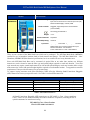
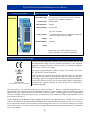
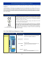
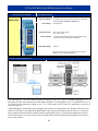
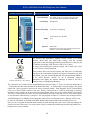
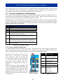
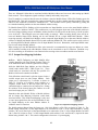
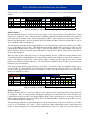
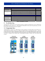
Contact Closure Output Connections Figure 27: MXCC-OP Mating Connections
2.3.3. DigitalDataLinkOperationalSettings
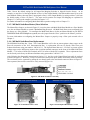
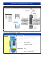
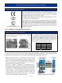
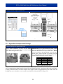
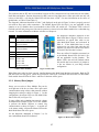
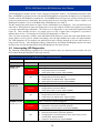
Address Settings for Digital Data Link Use a small screwdriver to press on the latches
(indentations) at the top and bottom of the front housing
cover. Slide housing forward to open.
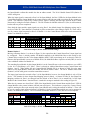
Figure 28: Latches
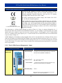
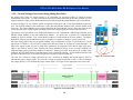
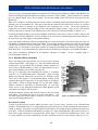
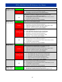
Channel Select: A two position DIP switch, SW1, is used
to select a backplane channel to communicate with the
Multi-Node Base module in a single module stack. Do not
set two I/O modules in the same module stack to the same
channel setting. Each I/O module in a module stack must
have a different Channel Select to function properly. The 4
possible channel selections are shown in Table 4.
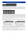
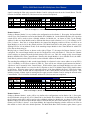
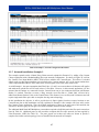
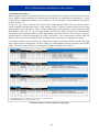
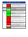
SW1 – Channel Select Switch Channel Position 1 Position 2 00 OFF OFF 01 OFF ON 10 ON OFF 11 ON ON Figure 29: Channel Switch
Table 4: Digital I/O Channel Select
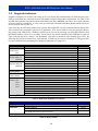
An I/O communication channel must be selected for each Digital Data Link. Open the module as shown in Figure
28 using a small screwdriver to release the front cover latches at both the top and bottom of the module. Slide the
housing front cover forward to reveal a small 2-position DIP switch marked SW1 (Figure 29).
33