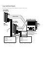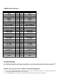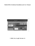
1
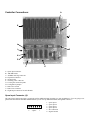
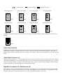
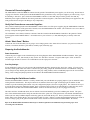
MultiJAMMA Controller Installation and User’s Manual
© 2000, Clay Cowgill Revision 1.0
Notice Regarding this Kit
Warning!
Although this kit has been tested and the techniques used
will not directly cause harm to your video games, if you do
something wrong you can very seriously damage the game
electronics!
To perform this kit installation you should:
• Be familiar with safe handling procedures for electronic components.
• Be able to remove and install new power supplies without causing damage.
• Be able to build cable harnesses for power and (optionally) control inputs.
• Be able to follow directions.
Arcade games are rugged equipment, but anytime you start messing around with something (particularly
something electronic) you accept a certain amount of risk that you may break something.
This kit carries with it no guaranty of compatibility to your particular game. Although this kit has been tested
with numerous JAMMA game boards it is possible that there are JAMMA boards that are incompatible. If you
carefully follow these instructions, you should do fine and everything should work. If you feel the complexity of
this system is beyond your ability to install, please hire someone local to you to perform the installation. Due to
the custom nature of every installation, technical support from Multigame.com is limited to kit behavior only.
Please read these instructions completely through before starting. If at any point you become lost of
confused, please consider hiring someone to perform the installation for you. One reversed power connection
and you’ll have a dead game board(s) and a damaged MultiJAMMA! Because of the risk of “user error”, this kit
is sold AS-IS. It has been tested and works 100% when shipped, but if anything happens to it that requires
repair it IS NOT a free service. Repair rates for the MultiJAMMA Controller start at $15 plus $7 return
shipping. Repair rates for the MultiJAMMA Switchboards start at $9 plus $7 return shipping. Be careful!
By using this kit you agree to the following terms and conditions:
Multigame.com makes no warranties on the MultiJAMMA, expressed, implied, statutory, or in any other
communication with you. Multigame.com specifically disclaims any implied warranty of merchantability or
fitness for a particular purpose. Multigame.com does not warrant that the operation of the MultiJAMMA will
be uninterrupted or error free. In no event will Multigame.com or any supplier of the MultiJAMMA be liable to
you or any other person or entity for any damages, including any incidental or consequential damages,
expenses, lost profits, lost savings, or other damages arising out of the use of or inability to use the
MultiJAMMA even if Multigame.com have been advised of the possibility of such damages. This kit is provided
AS-IS. By using the MultiJAMMA you agree to the above terms and conditions. If you choose not to abide by
these terms you must return the MultiJAMMA to the place of purchase within 7 days of receiving it for a full
refund, less any restocking fees and shipping/handing expenses.
MultiJAMMA Controller User Guide and Installation Manual Table of Contents:
INTRODUCTION: .......................................................................................................................................................................... 4
CONTROLLER FEATURES: ........................................................................................................................................................ 4
CONTROLLER CONNECTIONS: ................................................................................................................................................ 5
SPARE INPUT CONNECTOR (A):........................................................................................................................................................ 5
1PR/2PR HEADER (B):.................................................................................................................................................................... 6
JAMMA CARD-EDGE CONNECTOR (C): .......................................................................................................................................... 6
EXPANSION CONNECTOR (D):.......................................................................................................................................................... 6
GROUND POINT (E):........................................................................................................................................................................ 6
AUXILIARY POWER CONNECTOR (F): ............................................................................................................................................... 6
COOLING FAN CONNECTION POINTS (G): ......................................................................................................................................... 6
CONFIGURATION JUMPERS (H):........................................................................................................................................................ 6
GAME SELECT SWITCH (I): .............................................................................................................................................................. 7
GAME SELECT CONNECTOR (J):....................................................................................................................................................... 7
EIGHT 40 PIN CONNECTORS FOR SWITCHBOARDS (K):....................................................................................................................... 7
GETTING STARTED:.................................................................................................................................................................... 8
THE MULTIJAMMA WILL NOT: ..................................................................................................................................................... 8
THE MULTIJAMMA WILL:............................................................................................................................................................. 8
MONITOR SELECTION: .............................................................................................................................................................. 8
POWER SUPPLY SELECTION: ................................................................................................................................................... 8
TOOLS/SUPPLIES REQUIRED:................................................................................................................................................... 9
MULTIJAMMA CONTROLLER INSTALLATION:................................................................................................................... 9
JUMPER SETTINGS:.......................................................................................................................................................................... 9
FAN CONNECTIONS: ........................................................................................................................................................................ 9
REMOVE POWER FROM THE CABINET: .............................................................................................................................................. 9
CONNECT ALL GROUNDS TOGETHER: ............................................................................................................................................. 10
VERIFY THAT GROUNDS ARE CONNECTED TOGETHER:..................................................................................................................... 10
ATTACH “NEXT GAME” BUTTON:.................................................................................................................................................. 10
PREPARING THE SWITCHBOARDS: .................................................................................................................................................. 10
Power Connection:.................................................................................................................................................................. 10
Free Play Settings:.................................................................................................................................................................. 10
CONNECTING THE SWITCHBOARD CABLES:..................................................................................................................................... 10
SMALL INSTALLATION EXAMPLE:....................................................................................................................................... 11
LARGE INSTALLATION EXAMPLE:....................................................................................................................................... 12
JAMMA PINOUT REFERENCE: ...................................................................................................................................................... 13
TROUBLESHOOTING:............................................................................................................................................................... 13
ANYTIME YOU SUSPECT AN ERROR, ALWAYS CHECK THE FOLLOWING FIRST: .................................................................................... 13
DIM PICTURE ON MONITOR. ........................................................................................................................................................... 14
MONITOR DISPLAY ROLLS OR WON’T SYNC. .................................................................................................................................... 14
GAME GRAPHICS MESSED UP/GAME DOESN’T DISPLAY PICTURE. ....................................................................................................... 14
NO SOUND, OR POOR QUALITY SOUND. ........................................................................................................................................... 14
GAMES GENERATE CREDITS OR START WHEN THE CABINET IS TURNED ON......................................................................................... 14
ADDITIONAL HELP AND INFORMATION: ............................................................................................................................ 14
Introduction:
The MultiJAMMA system is designed to allow up to eight JAMMA standard arcade game boards to be connected in a single cabinet
and allow easy electronic switching between the games with the push of a button.
A MultiJAMMA installation will consist of a MultiJAMMA Controller and anywhere from two to eight MultiJAMMA
Switchboards. The Controller coordinates switching between the games while the Switchboards handle the actual electrical signal
routing. Switchboards connect to the MultiJAMMA Controller by a 40 pin ribbon cable. JAMMA Game boards plug into the
Switchboards and the MultiJAMMA Controller plugs into the JAMMA harness in the arcade game cabinet.
Because most arcade game power supplies are designed to run a single arcade game board, you will need to add additional power
supplies to the game cabinet to power all of the boards.
Controller Features:
•
Each Controller board can switch up to 8 JAMMA games with the push of a button.
•
Works for coin-operated or free-play. (Coin drops only credit the selected game. Service switch only credits the selected game.)
•
Free-play mode generates "virtual credits" so it works with game boards that don't have a built-in free-play setting. (Early classic
games, etc.)
•
Allows boards with or without built-in free-play settings to be easily mixed and matched -- just press Start and the game starts!
•
Game-select switch included on MultiJAMMA main board for easier installation and trouble-shooting. (No need to go around
front and hit the game-select button when working inside the cabinet.)
•
Microprocessor controlled for fast, flexible switching.
•
No "dead spots". The Controller will only cycle through the number of game boards attached (2 to 8), so if you run with less
than 8 boards you won't see a black screen when switching over "empty" slots.
•
Remembers the last selected game and automatically powers-up with it selected the next time the game is turned on.
•
Expandable. Start with a two-game switcher and then add additional Switchboards as your needs and board collection grows.
•
Controller board includes two 12V fan outputs for additional cabinet cooling if desired.
•
Supports a variety of Switchboards. (Initially JAMMA is available, but other standards such as Konami 36 pin, Sega 56 Pin,
Capcom 56 Pin, Nintendo, etc. are planned to allow direct connection of other board types without needing an additional
JAMMA adapter on the board.)
•
All game boards are powered for instantaneous switching and no "bootup" time. A must for location/coin-op use!
•
Uses inexpensive and reliable "PC" type power supplies and IDE hard-drive cables for connections.
Controller Connections:
A
B
K
C
J
D
I
H
G
F
E
A = Spare input connector.
B = 1PR/2PR header.
C = JAMMA card-edge connector.
D = Expansion connector.
E = Ground point.
F = Auxiliary power connector.
G = Cooling fan connection points.
H = Configuration jumpers.
I = Game select switch.
J = Game select connector.
K = Eight 40 pin connectors for Switchboards.
Spare Input Connector (A):
The spare input connector provides a ground pin and four additional input lines that go to each Switchboard. If you are going to use
games with more than the standard JAMMA buttons you can wire up additional buttons through this connector.
6
“Spare”
1
1 = spare input 1
2 = spare input 2
3 = spare input 3
4 = spare input 4
5 = No Connection
6 = Signal Ground
1PR/2PR Header (B):
This connector is reserved for future expansion.
JAMMA Card-Edge Connector (C):
This card-edge plugs into the JAMMA harness in the arcade game cabinet that you’re equipping with the MultiJAMMA. Only
+5VDC and Ground are necessary for power on the harness, however be aware that any signals you need for the game boards you’re
attaching need to be present on the connector. (This is mainly an issue for some “home-made” JAMMA cables that only connect the
minimum number of wires needed for a particular game and not all 56 wires.)
Expansion Connector (D):
This connector is reserved for future expansion.
Ground Point (E):
This is a point that is available to directly connect the power supply ground from any additional power supplies you add to the
cabinet. It is critical that all power supplies are connected to the same ground reference!
Auxiliary Power Connector (F):
This connector is a standard “PC” hard-drive/floppy drive power connector. If you want to power additional 12Volt fans from the
MultiJAMMA Controller you need to connect +12VDC to this connector. This also server as a ground point for additional power
supplies if Ground Point (E) is already used or inconvenient. It is critical that all power supplies are connected to the same ground
reference!
+12V DC
Ground
Ground
+5V DC
Front, Top Down
View
Cooling Fan Connection Points (G):
These are for two .1” spaced headers to allow connection of standard “PC” type 12V cooling fans. Since there is some risk that you
could attach a switch to one of the fan headers instead of the “Game Select” header these are left unpopulated unless you choose to
use them. You may solder pin headers into the holes, or solders wires for the fans directly there as well.
Configuration Jumpers (H):
The MultiJAMMA uses four jumpers for configuration settings. These jumpers tell the Controller how many games are attached to
the system, as well as if the games should be operated in free-play mode or not. The MultiJAMMA is shipped with the jumpers set
for an eight game system, with free-play turned off.
= Jumper Off Pins
Two Game System
Three Game System
A
B
C
FREE
Six Game System
= Jumper On Pins
Four Game System
A
B
C
FREE
Seven Game System
A
B
C
FREE
= Jumper On or OFF
A
B
C
FREE
Eight Game System
A
B
C
FREE
A
B
C
FREE
Five Game System
A
B
C
FREE
Reserved (do not use)
A
B
C
FREE
In addition to the above settings, the system can be set to free-play by closing the “FREE” jumper in addition to any of the above
settings:
A
B
C
FREE
Game Select Switch (I):
Located above the Jumpers is the Game Select Switch. Pressing this button when the system is on and operating will result in the
MultiJAMMA Controller selecting the game in the next slot. (Up to the limit set by the configuration jumpers.) This button is
meant to make installation and testing easier since it functions even when the “main” Game Select button isn’t yet hooked up in the
cabinet.
Game Select Connector (J):
The Game Select Connector is a .1” two-pin header that is used to connect the “main” Game Select button for the system. The size
of the button and mounting location of this button is up to the user, but it should be a Normally Open momentary type. (Just like a
“normal” arcade game button.) Closing the switch that attaches to these contacts results in the MulciJAMMA Controller selecting
the game in the next slot. (Up to the limit set by the configuration jumpers.)
Eight 40 pin connectors for Switchboards (K):
These eight connectors go to the MultiJAMMA Switchboards. Switchboards come with cables and are keyed to prevent inserting
them backwards. If longer cables are necessary for your particular installation you may use standard “PC” IDE Hard-drive cables.
Note that longer cables (or poor quality short cables) can effect video and audio quality in some cases.
Getting Started:
The MultiJAMMA is really just a fancy “switchbox”. When told to, it will disconnect signals from one point and reconnect them at
another point. The signals coming out of the MultiJAMMA Controller will only be as good as the signals going in (“garbage in,
garbage out”). Installing the MultiJAMMA Controller into a cabinet that isn’t 100% functional, has flaky controls, a bad picture,
etc, will just let you have up to eight games in a cabinet that isn’t 100% functional, has flaky controls, and a bad picture. The system
will only perform as well as the cabinet hardware allows it.
The MultiJAMMA Will Not:
•
•
•
•
Rotate Horizontal Games to play on a Vertical monitor.
Rotate Vertical Games to play on a Horizontal monitor.
Automatically adjust the monitor settings to games with different sync rates.
Run reliably (or safely!) unless additional power is provided in the cabinet (extra power supply(s) required).
The MultiJAMMA Will:
•
•
•
•
Switch between up to eight games without needing to plug and un-plug game boards inside the cabinet.
Allow all games to use free-play. (Even those without free-play settings.)
Switch only through the number of games you have attached.
…and lots of other stuff!
There are some important considerations when using the MultiJAMMA. In particular, Monitor selection and Power Supply.
Monitor Selection:
The MultiJAMMA will work best with an "auto-sync" (multi-sync) type game monitor. (In general this is most any monitor made
after about 1994 or so, and most any that came in a factory-built "JAMMA cabinet", but there are other ones as well.) It is possible to
use the MultiJAMMA on an older manual-sync monitor, but depending on your game boards the display on some games could "roll"
or not sync without manually tweaking the monitor controls when you switch games.
To test your monitor you can do the following:
1.
Collect the game boards you would like to use with the MultiJAMMA.
2.
One at a time, plug in each game board and turn on your game. Make sure the picture looks "normal" without having to make
any adjustments on the monitor.
If the monitor did not sync on one or more of the games, or if you had to manually tweak the monitor to get it to sync (I
warned you not to!), the MultiJAMMA will act the same way. (So if one of the games "rolls" on the monitor without the
MultiJAMMA, it will do the same through the MultiJAMMA too!)
You may be able to set an older manual-sync monitor to a setting that will sync for all the games through trial and error. It will
depend on the monitor and the games however.
Power Supply Selection:
You will need to add an additional power supply (or two) to your game cabinet to supply power for the game boards. It is not
included with the MultiJAMMA. The MultiJAMMA will use the power supply in your JAMMA cabinet for its own power, but
additional power is needed for game boards connected to the MultiJAMMA Switchboards. The switching power supplies used in
personal computers are recommended for use with the MultiJAMMA.
Power requirements for the additional power supply(s) will vary with your games, but in general you can use the following guideline:
1.
2.
3.
Assume 5 Amps of +5 Volt power for every game board.
Assume 1 Amp of +12 Volt power for every game board.
Some -5V current (for some games only).
When in doubt, go with bigger power supplies.
Following this example, a full 8-game MultiJAMMA would require:
8 * 5 Amps = 40 Amps of +5 Volt power
8 * 1 Amps = 8 Amps of +12 Volt power
Some -5V supply
Since most "PC" power supplies are rated for about 20A of +5 Volt power, a "safe" configuration would be two PC power supplies-one for every four games. (The 5 Amp per game "rule of thumb" already has safety margin calculated in, so being right at the rated
limit of the power supply is OK since the rating should be "overkill" already.)
Users with electronics experience can measure the current being drawn by their games and select a power supply more specifically
suited for their application if so desired.
If in doubt, buy a power supply that you know supplies more current than you need. Don’t skimp on buying the power supplies
either-- they’re supplying power to your game boards, and you don’t want a bad power supply failing and killing your boards!
Be sure to read the section in the MultiJAMMA Switchboard Manual about power supply wiring and connections.
Tools/Supplies Required:
Most installations will need some simple tools and supplies to get started.
•
•
•
•
•
•
•
A 100% working JAMMA Arcade Game Cabinet with an auto-sync monitor.
One or two extra power supplies (depending on number of games).
Wood screws (to mount the MultiJAMMA Controller to the side of the cabinet if so desired).
Screw driver (to go with the wood screws).
Wire cutter, electrical tape, connectors, etc. (For hooking up power supplies and extra button inputs.)
JAMMA Arcade Game boards you want to use.
A Multimeter to check power supply operation and verify wiring.
MultiJAMMA Controller Installation:
Jumper Settings:
Start by setting the jumpers on the MultiJAMMA to the number of games you want to install and whether or not free-play mode is
activated. Use the diagrams in the “Configuration Jumpers (H)” section as a guide.
Fan Connections:
If you are going to use the MultiJAMMA controller to power any +12VDC fans for additional cooling, install the headers or wires
for the fans to the MultiJAMMA Controller now. (See “Cooling Fan Connection Points (G)” for reference.)
Remove Power from the Cabinet:
Make sure the cabinet you’re installing the MultiJAMMA into is turned off and unplugged.
Connect all Grounds together:
The MultiJAMMA Controller MUST be connected to the ground of the additional power supplies you will be using. Run at least an
18 gauge wire from the “GND” point on the MultiJAMMA to the ground lines on any extra power supplies you will be using. If you
are attaching a “disk drive” power lead to the MultiJAMMA controller’s socket that will provide the ground. Note that any
additional power supplies should also have their ground lines connected together. (This insures that all the power supplies have the
same ground reference and prevent damage to any components.)
Verify that Grounds are connected together:
Once you have attached ground on the MultiJAMMA Controller to the rest of the power supplies, plug the MultiJAMMA Controller
into the JAMMA Harness of the game and (if desired) secure the MultiJAMMA to the cabinet. (Be careful not to use screws that are
too long or will poke through the cabinet sides!)
Use a multimeter set to Ohms (resistance) to measure from the Ground on the MultiJAMMA Controller to the grounds of all the
power supplies and the JAMMA harness. All should read very low resistance (<1 ohm) indicating they’re directly connected
together.
Attach “Next Game” Button:
Connect the wires from the button you are going to use to change games to the “Game Select Connector” (see previous section for
location). The button should be a push-button, normally open, momentary type.
Preparing the Switchboards:
Power Connection:
Connect the power supplies to the Switchboards per the wiring diagrams in the MultiJAMMA Switchboard manual. If the game
only requires +5V, +12V, and Ground you may use the “PC” disk-drive connector. For games that require -5VDC or that will
consume larger amounts of current is it recommended to use the 8-pin power connector.
Free Play Settings:
If your installation is going to be coin-operated, the Switchboards should be jumpered to the “Pay/Coins” setting. If you are using
Free-Play and the game board does not have a built-in free play setting, jumper the Switchboard for the “Free/Phantom” setting. If
you are using Free-Play and the game board also has a free-play setting enabled, set the Switchboard jumpers for the “Free/Normal”
setting. These settings and jumper positions are described in the MultiJAMMA Switchboard manual.
Connecting the Switchboard cables:
Now that the MultiJAMMA Controller is securely mounted and your Switchboards are properly jumpered, you can attach the cables
coming from the Switchboards. The 40 pin connectors are numbered from one to eight. Switching begins at number one and
continues up to the maximum game number set by the configuration jumpers (from two to eight games). The connectors are keyed
to prevent cables from being installed backwards, but if you purchase longer cables or use other IDE driver cables they may not be
keyed like the cables that come with the MultiJAMMA. Exercise care that the cables you use are plugged in correctly.
The other end of the Switchboard cables (the one with the circuit board attached) goes to the JAMMA game boards. The “parts
side” of the Switchboard should be facing the same direction as the “parts side” of the game board. Note that the Switchboards are
NOT keyed since many JAMMA adapters and bootleg games do not include the key slot. The key location is noted on the edgeboard—make sure it matches the key slot on your game board if it exists. (Failure to connect the Switchboard properly can result in
incorrect voltages going to the game board which can result is destruction of the board and/or MultiJAMMA. Be careful.)
Refer to the MultiJAMMA Switchboard manual for a detailed explanation and additional setup and testing steps when
connecting the Switchboards.
Small Installation Example:
A typical small system (two to four games) will be something like this:
MultiJAMMA Switchboards
MultiJAMMA Controller
40 pin cables
To JAMMA
harness in
cabinet
To JAMMA
game boards
+12V
+5V
-5V
Ground MUST connect
to both Controller and
Switchboards!
Ground
Additional Power Supply:
+5V DC
+12V DC
-5V DC (some games)
Ground
(Typically a ~250W PC Power Supply)
Large Installation Example:
For a larger system (five or more games) multiple power supplies will often be used:
MultiJAMMA
Switchboards
40 pin cables
MultiJAMMA Controller
MultiJAMMA
Switchboards
To JAMMA
game boards
To JAMMA
harness in
cabinet
40 pin cables
+12V
+5V
-5V
Ground
First Power Supply:
+5V DC
+12V DC
-5V DC (some games)
Ground
(Typically a ~250W PC Power Supply)
+12V
+5V
-5V
Ground MUST connect
to both Controller,
Switchboards, and both
power supplies!
Second Power Supply:
+5V DC
+12V DC
-5V DC (some games)
Ground
(Typically a ~250W PC Power Supply)
JAMMA Pinout Reference:
Solder Side
GND
GND
+5VDC
+5VDC
-5VDC
+12VDC
- KEY Coin Counter # 2
Lock Out Coil # 2
Speaker (-)
Video Green
Video Sync
Service Switch
Tilt Switch
Coin Switch # 2
2P Start
2P Up
2P Down
2P Left
2P Right
2P Button 1
2P Button 2
2P Button 3
2P Button 4
GND
GND
Pin #
A
B
C
D
E
F
H
J
K
L
M
N
P
R
S
T
Y
V
W
X
Y
Z
a
b
c
d
e
f
Pin #
1
2
3
4
5
6
7
8
9
10
11
12
13
14
15
16
17
18
19
20
21
22
23
24
25
26
27
28
Parts Side
GND
GND
+5VDC
+5VDC
-5VDC
+12VDC
- KEY Coin Counter # 1
Lock Out Coin # 2
Speaker (+)
Video Red
Video Blue
Video GND
Test Switch
Coin Switch # 1
1P Start
1P Up
1P Down
1P Left
1P Right
1P Button 1
1P Button 2
1P Button 3
1P Button 4
GND
GND
(signals in “italic” are not supported on the MultiJAMMA.)
Troubleshooting:
The MultiJAMMA Controller is fully tested prior to shipment, so a hardware problem is relatively unlikely. Certain installation
errors can create situations that may look like a hardware fault—some of these include (but are not necessarily limited to):
Anytime you suspect an error, always check the following first:
•
•
•
Check voltages at the game board and at several points on the board, all should be within +/-10% of their specified value.
Are all power supplies connected by common grounds?
Is everything plugged in? (Obvious, but you’d be surprised how many times this causes problems!)
•
Test the cabinet with the MultiJAMMA unplugged and a known working JAMMA board to verify that the monitor, speakers,
and controls all work properly.
Dim picture on monitor.
Make sure that all the game boards are supplied with power and ground and that all grounds are common (connected together
somewhere). Test game boards without the MultiJAMMA in line to make sure it’s not a monitor problem. If you’re using IDE
cables that did not come with the kit they could be too long, or too fine of gauge wire and are degrading the video signal.
Monitor display rolls or won’t sync.
Is the monitor a fixed-scan monitor? The MultiJAMMA system can not automatically adjust sync rates. Test game boards without
the MultiJAMMA in line to make sure it’s not a monitor problem. If you’re using IDE cables that did not come with the kit they
could be too long, or too fine of gauge wire and are degrading the video signal.
Game graphics messed up/game doesn’t display picture.
Are you supplying -5V to the game board by way of the “High-Current” connector on the Switchboard? Some games will need -5V
for proper video output and to pass self-test. Test game boards without the MultiJAMMA in line to make sure it’s not a board
problem.
No sound, or poor quality sound.
Are you supplying -5V to the game board by way of the “High-Current” connector on the Switchboard? Some games will need -5V
for proper audio output. Test game boards without the MultiJAMMA in line to make sure it’s not a speaker or board problem. If
you’re using IDE cables that did not come with the kit they could be too long, or too fine of gauge wire and are degrading the audio
signal.
Games generate credits or start when the cabinet is turned on.
The MultiJAMMA Controller needs to start-up and reset itself before other game boards start monitoring their inputs for coin drops.
If the power supply in the cabinet that the MultiJAMMA is running from “comes up” slower than the other power supplies that run
the games, spurious credits/starts can occur as the MultiJAMMA initializes itself. This can usually be solved by disconnecting the
original cabinet power supply and running the MultiJAMMA off of one of the same power supplies that runs the game boards. An
alternate method is to run the MultiJAMMA controlled from a small power supply that is always on (bypassing the cabinet power
switch) and only have the game power supplies turn on with the main cabinet power switch.
Additional Help and Information:
If you’re still stuck, or if you’d like to see some more examples (in color) of MultiJAMMA installations please consult the
MultiJAMMA webpage and the FAQ there.
http://www.multigame.com/jamma.html
If you’re still confused, you may wish to hire a professional to perform the installation for you. Due to the custom nature of each
installation and the high risk of e-mail or telephone based instructions being misinterpreted, only “generic” help and troubleshooting
instructions can be provided by Multigame.com.