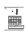
1
Concept
X(X)MIT-IEC / RTXMIT
Transmit (Receive) Function
Block
33002196.05
10/2006
2
Table of Contents
Safety Information . . . . . . . . . . . . . . . . . . . . . . . . . . . . . . . . . . . . 5
About the Book . . . . . . . . . . . . . . . . . . . . . . . . . . . . . . . . . . . . . . . 7
Chapter 1
Introduction to XXMIT and RTXMIT. . . . . . . . . . . . . . . . . . . . . . . 9
At a Glance . . . . . . . . . . . . . . . . . . . . . . . . . . . . . . . . . . . . . . . . . . . . . . . . . . . . . . 9
XXMIT Functionality . . . . . . . . . . . . . . . . . . . . . . . . . . . . . . . . . . . . . . . . . . . . . . 10
RTXMIT Functionality . . . . . . . . . . . . . . . . . . . . . . . . . . . . . . . . . . . . . . . . . . . . . 11
Chapter 2
XMIT: Transmit (Momentum) . . . . . . . . . . . . . . . . . . . . . . . . . . . 13
At a Glance . . . . . . . . . . . . . . . . . . . . . . . . . . . . . . . . . . . . . . . . . . . . . . . . . . . . .
Brief Description . . . . . . . . . . . . . . . . . . . . . . . . . . . . . . . . . . . . . . . . . . . . . . . . .
Representation . . . . . . . . . . . . . . . . . . . . . . . . . . . . . . . . . . . . . . . . . . . . . . . . . .
Parameter Description. . . . . . . . . . . . . . . . . . . . . . . . . . . . . . . . . . . . . . . . . . . . .
Description of Data Structure XMIT_SET . . . . . . . . . . . . . . . . . . . . . . . . . . . . . .
Description of Data Structure XMIT_CFG . . . . . . . . . . . . . . . . . . . . . . . . . . . . . .
XMIT ASCII Functions. . . . . . . . . . . . . . . . . . . . . . . . . . . . . . . . . . . . . . . . . . . . .
XMIT Communication Functions . . . . . . . . . . . . . . . . . . . . . . . . . . . . . . . . . . . . .
XMIT Modem Functions . . . . . . . . . . . . . . . . . . . . . . . . . . . . . . . . . . . . . . . . . . .
XMIT Modbus Functions . . . . . . . . . . . . . . . . . . . . . . . . . . . . . . . . . . . . . . . . . . .
FIFO and Flow Control . . . . . . . . . . . . . . . . . . . . . . . . . . . . . . . . . . . . . . . . . . . .
Run Time Errors . . . . . . . . . . . . . . . . . . . . . . . . . . . . . . . . . . . . . . . . . . . . . . . . .
Application Example . . . . . . . . . . . . . . . . . . . . . . . . . . . . . . . . . . . . . . . . . . . . . .
13
14
15
18
19
20
27
30
31
32
37
40
41
3
Chapter 3
XXMIT: Transmit (Compact, Momentum, Quantum) . . . . . . . . 47
At a Glance . . . . . . . . . . . . . . . . . . . . . . . . . . . . . . . . . . . . . . . . . . . . . . . . . . . . . 47
Brief Description. . . . . . . . . . . . . . . . . . . . . . . . . . . . . . . . . . . . . . . . . . . . . . . . . . 48
Representation. . . . . . . . . . . . . . . . . . . . . . . . . . . . . . . . . . . . . . . . . . . . . . . . . . . 49
Detailed Parameter Description . . . . . . . . . . . . . . . . . . . . . . . . . . . . . . . . . . . . . . 51
XXMIT Communication Functions . . . . . . . . . . . . . . . . . . . . . . . . . . . . . . . . . . . . 58
XXMIT ASCII Functions . . . . . . . . . . . . . . . . . . . . . . . . . . . . . . . . . . . . . . . . . . . . 59
XXMIT Modem Functions . . . . . . . . . . . . . . . . . . . . . . . . . . . . . . . . . . . . . . . . . . 64
XXMIT Modbus Functions . . . . . . . . . . . . . . . . . . . . . . . . . . . . . . . . . . . . . . . . . . 66
FIFO and Flow Control. . . . . . . . . . . . . . . . . . . . . . . . . . . . . . . . . . . . . . . . . . . . . 73
Run Time Errors. . . . . . . . . . . . . . . . . . . . . . . . . . . . . . . . . . . . . . . . . . . . . . . . . . 76
Application Example . . . . . . . . . . . . . . . . . . . . . . . . . . . . . . . . . . . . . . . . . . . . . . 77
Chapter 4
RTXMIT: Full Duplex Transmit
(Compact, Momentum, Quantum) . . . . . . . . . . . . . . . . . . . . . . 89
At a Glance . . . . . . . . . . . . . . . . . . . . . . . . . . . . . . . . . . . . . . . . . . . . . . . . . . . . . 89
Brief Description. . . . . . . . . . . . . . . . . . . . . . . . . . . . . . . . . . . . . . . . . . . . . . . . . . 90
Representation. . . . . . . . . . . . . . . . . . . . . . . . . . . . . . . . . . . . . . . . . . . . . . . . . . . 91
Parameter Description . . . . . . . . . . . . . . . . . . . . . . . . . . . . . . . . . . . . . . . . . . . . . 92
Runtime Errors. . . . . . . . . . . . . . . . . . . . . . . . . . . . . . . . . . . . . . . . . . . . . . . . . . . 96
Application Example . . . . . . . . . . . . . . . . . . . . . . . . . . . . . . . . . . . . . . . . . . . . . . 97
Chapter 5
Technical References for XXMIT function block. . . . . . . . . . 101
At a glance . . . . . . . . . . . . . . . . . . . . . . . . . . . . . . . . . . . . . . . . . . . . . . . . . . . . . 101
Modbus Query/Response Parameter Limits . . . . . . . . . . . . . . . . . . . . . . . . . . . 102
XXMIT Configuration using Hayes Compatible Dial-Up Modems (Only) . . . . . . 106
Chapter 6
Cabling Information . . . . . . . . . . . . . . . . . . . . . . . . . . . . . . . . . 111
At a Glance . . . . . . . . . . . . . . . . . . . . . . . . . . . . . . . . . . . . . . . . . . . . . . . . . . . . 111
Cable Pinouts. . . . . . . . . . . . . . . . . . . . . . . . . . . . . . . . . . . . . . . . . . . . . . . . . . . 112
Cable Adapter Kits . . . . . . . . . . . . . . . . . . . . . . . . . . . . . . . . . . . . . . . . . . . . . . . 126
4
Glossary
. . . . . . . . . . . . . . . . . . . . . . . . . . . . . . . . . . . . . . . . . . . . . . 127
Index
. . . . . . . . . . . . . . . . . . . . . . . . . . . . . . . . . . . . . . . . . . . . . . 151
Safety Information
§
Important Information
NOTICE
Read these instructions carefully, and look at the equipment to become familiar with
the device before trying to install, operate, or maintain it. The following special
messages may appear throughout this documentation or on the equipment to warn
of potential hazards or to call attention to information that clarifies or simplifies a
procedure.
The addition of this symbol to a Danger or Warning safety label indicates
that an electrical hazard exists, which will result in personal injury if the
instructions are not followed.
This is the safety alert symbol. It is used to alert you to potential personal
injury hazards. Obey all safety messages that follow this symbol to avoid
possible injury or death.
DANGER
DANGER indicates an imminently hazardous situation, which, if not avoided, will
result in death or serious injury.
WARNING
WARNING indicates a potentially hazardous situation, which, if not avoided, can result
in death, serious injury, or equipment damage.
CAUTION
CAUTION indicates a potentially hazardous situation, which, if not avoided, can result
in injury or equipment damage.
33002196
5
Safety Information
PLEASE NOTE
Electrical equipment should be installed, operated, serviced, and maintained only by
qualified personnel. No responsibility is assumed by Schneider Electric for any
consequences arising out of the use of this material.
© 2006 Schneider Electric. All Rights Reserved.
6
33002196
About the Book
At a Glance
Document Scope
This manual presents all information neccessary to configure the XMIT, XXMIT and
the RTXMIT function blocks on all PLC platforms supporting the IEC languages.
Validity Note
The information contained in this book is valid for Concept version 2.6 Service
release 1 and later.
Related
Documents
Title of Documentation
Reference Number
Concept Installation
840 USE 502 00
Concept User Manual
840 USE 503 00
Concept IEC Block Libraries
840 USE 504 00
You can download these technical publications and other technical information from
our website at www.telemecanique.com
User Comments
33002196
We welcome your comments about this document. You can reach us by e-mail at
[email protected]
7
About the Book
8
33002196
Introduction to XXMIT and RTXMIT
1
At a Glance
Overview
This chapter gives a general overview on the transmit function block XXMIT and the
transmit/receive function block RTXMIT.
What's in this
Chapter?
This chapter contains the following topics:
33002196
Topic
Page
XXMIT Functionality
10
RTXMIT Functionality
11
9
Introduction
XXMIT Functionality
Function
Overview
The XXMIT (Transmit) function block enable the use of the PLCs serial ports for
communication under the control of the application program.
The following communication types are supported:
Modbus as Master
Simple ASCII Input/Output
ASCII Input with one or two termination characters
Modem Communication
l
l
l
l
Function
Description
10
The Transmit blocks send Modbus messages from a "master" PLC to multiple slave
PLCs or sends ASCII character strings from the PLC's Modbus slave port #1 (on
Momentum PLCs also port #2 is supported) to ASCII printers and terminals. XXMIT
sends these messages over telephone dialup modems, radio modems, or simply
direct connections. The Transmit blocks perform general ASCII input functions in
the communication mode including simple ASCII and terminated ASCII. You may
import and export ASCII or binary data into your PLC. The block has builtin
diagnostics that checks to make sure no other Transmit blocks are active in the PLC
on the same port. Within the Transmit blocks, control inputs allows you to control the
communications link between the PLC and DCE (Data Communication Equipment)
devices attached to Modbus port #1 or port #2 of the PLC. The Transmit blocks do
NOT activate the port LED when transmitting data.
33002196
Introduction
RTXMIT Functionality
Function
Overview
The RTXMIT (Receive/Transmit) function block enable the use of the PLCs serial
ports for full duplex communication under the control of the application program.
The following communication types are supported:
l Simple ASCII Input/Output
l ASCII Input with one or two termination characters
Function
Description
33002196
The RTXMIT Transmit block sends ASCII character strings from the PLC's Modbus
slave port#1 (on Momentum PLCs also port#2 is supported) to ASCII printers,
terminals or any other serial device. The Transmit blocks perform general ASCII
input functions in the communication mode including simple ASCII and terminated
ASCII. You may import and export ASCII or binary data into your PLC. The RTXMIT
block can send and receive characters at the same time (full duplex). The block has
builtin diagnostics that checks to make sure no other Transmit blocks are active in
the PLC on the same port. Within the Transmit blocks, control inputs allows you to
control the communications link between the PLC and DCE (Data Communication
Equipment) devices attached to Modbus port #1 or port#2 of the PLC. The Transmit
blocks do NOT activate the port LED when transmitting data.
11
Introduction
12
33002196
XMIT: Transmit (Momentum)
2
At a Glance
Introduction
This chapter describes the XMIT function block.
What's in this
Chapter?
This chapter contains the following topics:
33002196
Topic
Page
Brief Description
14
Representation
15
Parameter Description
18
Description of Data Structure XMIT_SET
19
Description of Data Structure XMIT_CFG
20
XMIT ASCII Functions
27
XMIT Communication Functions
30
XMIT Modem Functions
31
XMIT Modbus Functions
32
FIFO and Flow Control
37
Run Time Errors
40
Application Example
41
13
XMIT: Transmit (Momentum)
Brief Description
Function
Description
The XMIT (Transmit) function block sends Modbus messages from a "master" PLC
to multiple slave PLCs or sends ASCII character strings from the PLC's Modbus
slave port #1 or port #2 to ASCII printers and terminals. XMIT sends these
messages over telephone dialup modems, radio modems, or simply direct
connection. XMIT performs general ASCII input functions in the communication
mode including simple ASCII and terminated ASCII. You may import and export
ASCII or binary data into your PLC and convert it into various binary data or ASCII
to send to DCE devices based upon the needs of your application. The block has
builtin diagnostics that checks to make sure no other XMIT blocks are active in the
PLC on the same port. Within the XMIT block a control table allows you to control
the communications link between the PLC and DCE (Data Communication
Equipment) devices attached to Modbus port #1 or port #2 of the PLC. The XMIT
block does NOT activate the port LED when it is transmitting data.Remember, the
Modbus protocol is a "master/slave" protocol. Modbus is designed to have only one
master polling multiple slaves. Therefore, when using the XMIT block in a network
with multiple masters, contention resolution and collision avoidance is your
responsibility and may easily be addressed through ladder logic programming.
EN and ENO can be configured as additional parameters
Using Modbus
Remember, the Modbus protocol is a "master/slave" protocol. Modbus is designed
to have only one master polling multiple slaves. Therefore, when using the XMIT
block in a network with multiple masters, contention resolution and collision
avoidance is your responsibility and may easily be addressed through user logic
programming.
Restrictions
This function block controls Modbus port #1 and #2 of the Momentum CPUs. It can
be used with the stripped exec only. The XMIT function block works just as its LL984
counterpart, but without ASCII string conversion, copy and compare functions and
without the Port Status functions.
Software and
Hardware
Required
When using the Momentum PLCs the XMIT function block it is a builtin.
14
The following hardware is not supported by the XXMIT function block:
l Soft PLC
l Atrium 386 and Atrium-S908 PLCs
l IEC Simulator
33002196
XMIT: Transmit (Momentum)
Representation
Symbol
Representation of the block
XMIT
ANY
XMIT_SET
BYTE
BOOL
BOOL
Parameter
Description
33002196
MSG_OUT
SET
PORT
START
ABORT
MSG_IN
CFG
ANY
XMIT_CFG
OP_ACT
NO_SUC
OP_SUC
Ext
BOOL
BOOL
BOOL
DINT
Description of the block parameter
Parameters
Data type
Meaning
SET
XMIT_SET
Data structure for the XMIT configuration
MSG_OUT
ANY
Message to be sent (must be in 4x range)
PORT
BYTE
Selection of communications interface
START
BOOL
1: Starts XMIT operation
ABORT
BOOL
1: Aborts current XMIT operation
MSG_IN
ANY
Incoming message (must be in 4x range)
CFG
XMIT_CFG
Data structure with all components of the XMIT
configuration, including the automatically set and not
used variables. Only for display and must be in 4x
range.
OP_ACT
BOOL
1: XMIT operation in progress
NO_SUC
BOOL
1: There is an error or the current XMIT operation is
aborted.
OP_SUC
BOOL
1: XMIT operation successfully completed
Ext
DINT
not presently in use
15
XMIT: Transmit (Momentum)
XMIT_SET Data
Structure
16
Description of data structure
Element
Data type
Meaning
BaudRate
WORD
This component corresponds to the 4x+3 register
(data rate) of the LL984 XMIT instruction.
DataBits
BYTE
This component corresponds to the 4x+4 register
(data bits) of the LL984 XMIT instruction.
Parity
BYTE
This component corresponds to the 4x+5 register
(parity) of the LL984 XMIT instruction.
StopBits
BYTE
This component corresponds to the 4x+6 register
(stop bits) of the LL984 XMIT instruction.
Command
Word
WORD
This component corresponds to the 4x+8 register
(command word) of the LL984 XMIT instruction.
MessageLen
WORD
This component corresponds to the 4x+10 register
(message length) of the LL984 XMIT instruction. (In
case of a terminated ASCII receipt, this component
will be set automatically.)
RespTimeOut WORD
This component corresponds to the 4x+11 register
(response time-out (ms)) of the LL984 XMIT
instruction.
RetryLimit
WORD
This component corresponds to the 4x+12 register
(retry limit) of the LL984 XMIT instruction.
XmStartDelay WORD
This component corresponds to the 4x+13 register
(start of transmission delay (ms)) of the LL984 XMIT
instruction.
XmEndDelay
This component corresponds to the 4x+14 register
(end of transmission delay (ms)) of the LL984 XMIT
instruction.
WORD
33002196
XMIT: Transmit (Momentum)
XMIT_CFG Data
Structure
33002196
Description of data structure
Element
Data type
Meaning
FaultStatus
WORD
This component corresponds to the 4x+1 register
(fault status) of the LL984 XMIT instruction.
UserAvail_1
WORD
This component corresponds to the 4x+2 register
(available to user) of the LL984 XMIT instruction.
BaudRate
WORD
This component corresponds to the 4x+3 register
(data rate) of the LL984 XMIT instruction.
DataBits
WORD
This component corresponds to the 4x+4 register
(data bits) of the LL984 XMIT instruction.
Parity
WORD
This component corresponds to the 4x+5 register
(parity) of the LL984 XMIT instruction.
StopBits
WORD
This component corresponds to the 4x+6 register
(stop bits) of the LL984 XMIT instruction.
UserAvail_2
WORD
This component corresponds to the 4x+7 register
(available to user) of the LL984 XMIT instruction.
Command
Word
WORD
This component corresponds to the 4x+8 register
(command word) of the LL984 XMIT instruction.
MessagePtr
WORD
This component corresponds to the 4x+9 register
(message pointer) of the LL984 XMIT instruction.
MessageLen
WORD
This component corresponds to the 4x+10 register
(message length) of the LL984 XMIT instruction.
RespTimeOut WORD
This component corresponds to the 4x+11 register
(response time-out (ms)) of the LL984 XMIT
instruction.
RetryLimit
This component corresponds to the 4x+12 register
(retry limit) of the LL984 XMIT instruction.
WORD
XmStartDelay WORD
This component corresponds to the 4x+13 register
(start of transmission delay (ms)) of the LL984 XMIT
instruction.
XmEndDelay
WORD
This component corresponds to the 4x+14 register
(end of transmission delay (ms)) of the LL984 XMIT
instruction.
CurrentRetry
WORD
This component corresponds to the 4x+15 register
(current retry) of the LL984 XMIT instruction.
17
XMIT: Transmit (Momentum)
Parameter Description
MSG_OUT
MSG_OUT contains the message data to be transferred, for example, ASCII
characters for an ASCII transfer, definition of termination characters for terminated
ASCII input or Modbus templates for Modbus master messages.
The data type that must be assigned to the parameter has to be a data type WORD
array. This array has to be assigned to a 4x register range. The field length must
equal the length of the MSG_IN field. If the field is assigned to the range for
Unlocated variables, a runtime error message will be generated.
SET
SET contains the configuration of the XMIT function block in form of the XMIT_SET
data structure. This parameter may be assigned to an Unlocated variable.The data
structure components have the same function as the components of the LL984
XMIT configuration. There is only one difference, the variables are set automatically
by the system and the unused variables are not shown in this data structure. This
means, a complete configuration requires that all components in this data structure
have to be defined.
PORT
PORT specifies the communications interface. The only authorized values are 1 and
2.
START
A 1-signal at START initiates the XMIT operation. The 1-signal must be applied until
the operation has finished or until an error has occurred.
ABORT
A 1-signal terminates the current XMIT operation and writes the abort code "121" to
the "FaultStatus" component of the XMIT_CFG data structure at the CFG output.
MSG_IN
MSG_IN contains the incoming message data, for example, terminated ASCII input
or responses of a Modbus master command which was previously sent by the XMIT
function block.The data type that must be assigned to the parameter has to be a
data type WORD array. This array has to be assigned to a 4x register range. The
field length must equal the length of the MSG_OUT field. If the field is assigned to
the range for Unlocated variables, a runtime error message will be generated.
CFG
CFG contains an XMIT function block copy of the configuration defined on SET
which has the form of data structure XMIT_CFG, it includes the automatically set
and not used variables.The data structure components have the same function as
the components of the LL984 XMIT configuration.This data structure has to be
assigned to a 4x register range. If the data structure is assigned to the range for
Unlocated variables, a runtime error message will be generated. CFG is used to
verify the actually applied configuration.
18
33002196
XMIT: Transmit (Momentum)
OP_ACT
A 1-signal indicates that an XMIT operation is in progress.
NO_SUC
A 1-signal indicates that an error has occurred or that the current XMIT operation is
terminated.
OP_SUC
A 1-signal indicates that the XMIT operation has been completed successfully.
EXT
Presently not use. Do not connect
Description of Data Structure XMIT_SET
XMIT_SET
This data structure contains the particular configuration for the XMIT operation. This
variable may be stored in the unlocated memory. The elements of this structure
have the same meaning as the corresponding elements of the XMIT_CFG (see
Description of Data Structure XMIT_CFG, p. 20) structure. XMIT_SET is used to
configure the XMIT block. The values of this data structure are transfered to
XMIT_CFG.
Note: XMIT_SET does not contain the MessagePtr element. This is automatically
set to the adress of the MSG_IN array and placed into XMIT_CFG.
33002196
19
XMIT: Transmit (Momentum)
Description of Data Structure XMIT_CFG
At a Glance
This data structure contains the actual configuration data the XMIT block uses. Do
not write directly to this array, as the content is automatically generated or copied
from XMIT_SET. The following is a detailed description of each of the (16) XMIT
communication control table registers.
XMIT_CFG.Revis
ion Read Only
Displays the current revision number of XMIT block. This number is automatically
loaded by the function block and over writes any other number entered into this
register.
XMIT_CFG.Fault
Status Read
Only
This field displays a fault code generated by the XMIT block. A complete list is
shown in the table below.
20
Fault Code
Fault Description
1
Modbus exception - Illegal function
2
Modbus exception - Illegal data address
3
Modbus exception - Illegal data value
4
Modbus exception - Slave device failure
5
Modbus exception - Acknowledge
6
Modbus exception - Slave device busy
7
Modbus exception -Negative acknowledge
8
Modbus exception -Memory parity error
9 ... 99
Reserved
100
Slave PLC data area cannot equal zero
101
Master PLC data area cannot equal zero
102
Coil (0x) not configured
103
Holding register (4x) not configured
104
Data length cannot equal zero
105
Pointer to message table cannot equal zero
106
Pointer to message table is outside the range of configured holding registers
(4x)
107
Transmit message time-out (This error is generated when the UART cannot
complete a transmission in 10 seconds or less. This error bypasses the retry
counter and will activate the error output on the first error).
108
Undefined error
109
Modem returned ERROR
110
Modem returned NO CARRIER
33002196
XMIT: Transmit (Momentum)
XMIT_CFG.User
Avail_1
33002196
Fault Code
Fault Description
111
Modem returned NO DIALTONE
112
Modem returned BUSY
113
Invalid LRC checksum from the slave PLC
114
Invalid CRC checksum from the slave PLC
115
Invalid Modbus function code
116
Modbus response message time-out
117
Modem reply time-out
118
XMIT could not gain access to PLC communications port #1 or port #2
119
XMIT could not enable PLC port receiver
120
XMIT could not set PLC UART
121
User issued an abort command
122
not used
123
not used
124
Undefined internal state
125
Broadcast mode not allowed with this Modbus function code
126
DCE did not assert CTS
127
Illegal configuration (data rate, data bits, parity, or stop bits)
128
Unexpected response received from Modbus slave
129
Illegal command word setting
130
Command word changed while active
131
Invalid character count
132
Invalid register block
133
ASCII input FIFO overflow error
134
Invalid number of start characters or termination characters
The XMIT block does not use this register. However, it may be used in the user logic
as a pointer.
21
XMIT: Transmit (Momentum)
XMIT_CFG.Data
Bits
XMIT supports the following data bits: 7 and 8. To configure a data bit size, enter
its decimal number into this element. Modbus messages may be sent in ASCII
mode or RTU mode. ASCII mode requires 7 data bits, while RTU mode requires
8 data bits. When sending ASCII character message you may use either 7 or 8 data
bits. When an invalid data bit is entered, the block displays an illegal configuration
error (error code 127) in the XMIT_CFG.FaultStatus element. For more details on
Modbus message formats refer to Modicon Modbus Protocol Reference Guide
(PI MBUS 300).
XMIT_CFG.Parity
XMIT supports the following parity: none, odd and even. Enter a decimal of either:
0 = no parity, 1 = odd parity, or 2 = even parity. When an invalid parity is entered,
the block displays an illegal configuration error (error code 127) in the
XMIT_CFG.FaultStatus element.
XMIT_CFG.Stop
Bits
XMIT supports one or two stop bits. Enter a decimal of either: 1 = one stop bit, or
2 = two stop bits. When an invalid stop bit is entered, the block displays an illegal
configuration error (error code 127) in the XMIT_CFG.FaultStatus element.
XMIT_CFG.User
Avail_2
The XMIT block does not use this element. However, it may be used in the user
logic as a pointer.
XMIT_CFG.
CommandWord
The XMIT interprets each bit of the command word as a function to perform. If bit 7
and 8 are on simultaneously or if any two or more of bits 13, 14, 15 or 16 are on
simultaneously or if bit 7 is not on when bits 13, 14, 15, or 16 are on error 129 will
be generated. Other restrictions apply. For more details refer to Command Word
Bits, p. 30 . The individual bit definitions are shown in the table below.
Bit
Definition
Bit 1 (msb)
Reserved
Bit 2 Enable RTS/CTS modem control Set to 1 when a DCE connected to the PLC requires
hardware handshaking using RTS/CTS control.
This bit may be used in conjunction with values
contained in XMIT_CFG.XmStartDelay and
XMIT_CFG.XmEndDelay. Start of transmission
delay keeps RTS asserted for (X mS) before XMIT
sends message out of PLC port. Likewise, end of
transmission delay keeps RTS asserted for (X mS)
after XMIT has finished sending a message out of
the PLC port. Once the end of transmission delay
expires XMIT de-assert RTS.
Bit 3 Enable RS485 mode
22
Set to 1 when the selected port should operate in
RS485 mode. Otherwise it defaults to 0, which is
RS232 mode.
33002196
XMIT: Transmit (Momentum)
Bit
33002196
Definition
Bit 4
Reserved
Bit 5 Terminated ASCII input
Set to 1 to remove and discard all characters from
FIFO until the starting string is matched, then these
starting characters and subsequent characters are
written into the MSG_IN array until the terminator
sequence is matched. The terminator string is also
written into the MSG_IN array. Refer to chapter
"Terminated ASCII Input Function (see Terminated
ASCII Input Function, p. 27)" for more details.
Bit 6 Simple ASCII input
Set to 1 to remove the ASCII characters from FIFO
for writing into the MSG_IN array. The Message
pointer (XMIT_CFG.MessagePtr) is automatically
set to the register address specified for the MSG_IN
array. Refer to chapter "Simple ASCII Input
Function (see Simple ASCII Input Function, p. 29)"
for more details.
Bit 7 Enable ASCII string messaging
Set to 1 when you want to send ASCII messages out
of the PLC. XMIT sends ASCII strings up to 1024
characters in length. You program the ASCII
message into the MSG_OUT array. Two characters
allowed per register. Only use Bit 7 OR Bit 8, do not
try to use both. Refer to chapter "ASCII String
Messaging (see ASCII String Messaging, p. 29) " for
more details.
Bit 8 Enable Modbus messaging
Set to 1 when you want to send Modbus messages
out of the PLC. Modbus messages may be in either
RTU or ASCII formats. When data bits=8, XMIT
uses Modbus RTU format. When data bits=7, XMIT
uses Modbus ASCII format. Only use Bit 7 OR Bit 8,
do not try to use both.
Bit 9 Enable ASCII receive FIFO
Set to 1 to allow the XMIT block to take control over
the selected port (1 or 2) from the PLC. The block
begins to receive ASCII characters into an empty
512 byte circular FIFO. Refer to chapter "ASCII
Receive FIFO (see ASCII Receive FIFO, p. 37)" for
more details.
23
XMIT: Transmit (Momentum)
24
Bit
Definition
Bit 10 Enable back space
Set to 1 to allow special handling of ASCII back
space character (BS, 8Hex). When using either
Simple ASCII Input (Bit 6) or Terminated ASCII Input
(Bit 5) each back space character is removed from
FIFO and may or may NOT be stored into the
MSG_IN array. Refer to chapter "Enable Back
space (see Enable Back space, p. 37)" for more
details.
Bit 11 Enable RTS/CTS flow control
Set to 1 to allow full duplex hardware flow control
using the RTS and CTS handshaking signals for
ASCII massaging. The RTS/CTS operates in both
the input and output modes. Refer to chapter
"Enable RTS/CTS Flow Control (see Enable RTS/
CTS Flow Control, p. 38)" for more details.
Bit 12 Enable Xon/Xoff flow control
Set to 1 to allow full duplex software flow control
using the ASCII Xon character (DC1, 11 Hex) and
the ASCII Xoff character (DC3, 13 Hex). The Xon/
Xoff operates in both the input and output modes.
Refer to chapter "Enable Xon/Xoff Flow Control (see
Enable Xon/Xoff Flow Control, p. 39)" for more
details.
Bit 13 Pulse dial modem
Set to 1 when using a Hayes compatible dial-up
modem and you wish to pulse dial a telephone
number. You program the phone number into the
MSG_IN array. The length of the message must be
in XMIT_SET.MessageLen. Pulse dialed numbers
are sent to the modem automatically preceded by
ATDP and with carriage return <CR> and line feed
<LF> appended. Since the dial message is an
ASCII string, bit 7 must be ON prior to sending the
number to be dialed.
Bit 14 hangup modem
Set to 1 when using a Hayes compatible dial-up
modem and you want to hangup the modem. You
must use ladder logic to turn this bit ON. Since the
hangup message is an ASCII string, bit 7 must be
ON prior to sending the message. Hang up
messages are sent to the modem automatically
preceded by +++AT and with carriage return <CR>
and line feed <LF> appended. XMIT looks for a
correct disconnect response from the modem before
it turns ON the OP_SUC output signal, noting a
successful completion.
33002196
XMIT: Transmit (Momentum)
Bit
Definition
Bit 15 Tone dial modem
Set to 1 when using a Hayes compatible dial-up
modem and you wish to tone dial a telephone
number. The the dial message must be placed in
MSG_OUT array and the length of the message in
XMIT_SET.MessageLen. Tone dial numbers are
sent to the modem automatically preceded by ATDT
and with carriage return <CR> and line feed <LF>
appended. Since the dial message is an ASCII
string, bit 7 must be ON prior to sending the number
to be dialed.
Bit 16 Initialize modem
Set to 1 when using a Hayes compatible dial-up
modem and you want to initialize the modem. You
program the initialization message into the
MSG_OUT array and the length of the message
XMIT_SET.MessageLen. All messages are sent to
the modem automatically preceded by AT and with
a carriage return <CR> and line feed <LF>
appended. Since the initialization message is an
ASCII string, bit 7 must be ON prior to sending the
message.
XMIT_CFG.
MessagePtr
This pointer is automatically handled by the XMIT block. It points to the beginning of
the message table which is either the MSG_IN (see MSG_IN, p. 18) array or the
MSG_OUT (see MSG_OUT, p. 18) array depending on the chosen XMIT function.
Each array element (4x register) holds up to two ASCII characters. Each ASCII
string may be up to 1024 characters in length. For example, when you want to send
10 ASCII messages out of the PLC, you must transfer the10 ASCII characters
strings into the MSG_OUT array one after another after each successful operation
of XMIT.
XMIT_CFG.
MessageLen
You enter the length of the current message. When XMIT is sending Modbus
messages for function codes 01, 02, 03, 04, 05, 06, 08, 15 and 16, the length of the
message is automatically set to five. When XMIT is receving Terminated ASCII
input the length of the message must be set to five or an error results. When XMIT
is sending Modbus messages for function codes twenty and twenty-one, the length
of the message is automatically set to six. When XMIT is sending ASCII messages,
the length may be 1 ... 1024 ASCII characters per message.
33002196
25
XMIT: Transmit (Momentum)
XMIT_CFG.Resp
TimeOut
You enter the time value in milliseconds (ms) to determine how long XMIT waits for
a valid response message from a slave device (PLC, modem, etc.). In addition, the
time applies to ASCII transmissions and flow control operations. When the
response message is not completely formed within this specified time, XMIT issues
a fault. The valid range is 0 ... 65535 ms. The timeout is initiated after the last
character in the message is sent.
XMIT_CFG.Retry
Limit
You enter the quantity of retries to determine how many times XMIT sends a
message to get a valid response from a slave device (PLC, modem, etc.). When the
response message is not completely formed within this specified time, XMIT issues
a fault and a fault code. The valid range is 0 ... 65535 # of retries. This field is used
in conjunction with response time-out (4x + 11).
XMIT_CFG.Start
Delay
You enter the time value in milliseconds (ms) when RTS/CTS control is enabled, to
determine how long XMIT waits after CTS is received before it transmits a message
out of the PLC port #1. Also, you may use this register even when RTS/CTS is NOT
in control. In this situation, the entered time value determines how long XMIT waits
before it sends a message out of the PLC port #1. You may use this as a pre
message delay timer. The valid range is 0 ... 65535 ms.
XMIT_CFG.Xm
EndDelay
You enter the time value in milliseconds (ms) when RTS/CTS control is enabled, to
determine how long XMIT keeps RTS asserted once the message is sent out of the
PLC port #1. After the time expires, XMIT deassert RTS. Also, you may use this
register even when RTS/CTS is NOT in control. In this situation, the entered time
value determines how long XMIT waits after it sends a message out of the PLC port
#1. You may use this as a post message delay timer. The valid range is
0 ... 65535 ms.
XMIT_CFG.Xm
CurrentRetry
The value displayed here indicates the current number of retry attempts made by
the XMIT block. This register is read only.
26
33002196
XMIT: Transmit (Momentum)
XMIT ASCII Functions
At a Glance
The XMIT function block supports the following ASCII communication functions:
l Simple ASCII Input
l Terminated ASCII Input
l ASCII String Messaging
Terminated
ASCII Input
Function
When XMIT_CFG.CommandWord, Bit 5 is actived for terminated ASCII Input
messages, the MSG_OUT array has to contain the ASCII input definition table. The
terminated ASCII definition table is five registers long. The message length
XMIT_CFG.MessageLen is automatically set. The terminated ASCII input definition
table is shown in the table below.
Terminated ASCII Input Definition Table
Word
High Byte
Low Byte
MSG_OUT[1]
Number of starting characters (allowed
content = 0, 1, 2)
Number of terminator characters
(allowed content = 1, 2)
MSG_OUT[2]
First starting character
Second starting character
MSG_OUT[3]
First terminator character
Second terminator character
MSG_OUT[4]
Not used. Destination register is automatically set to MSG_IN
MSG_OUT[5]
Counter: counts the number of received characters written into the 4x
storage destination registers
During the process, MSG_OUT[5] holds a running count of characters written into
the MSG_IN array. Once the terminated string is received the OP_SUC output on
the XMIT block goes ON and MSG_OUT[5] holds the total length of the received
string including the starting and terminator strings. At this point the XMIT block stills
owns the port and continues to save newly received characters into the ASCII
receive FIFO, because the enable ASCII receive FIFO XMIT_CFG.CommandWord,
Bit 9 is ON.Using program logic, you can clear the simple ASCII input Bit before the
next scan, while leaving the enable ASCII receive FIFO Bit ON. Thus, MSG_IN is
NOT over written by newer FIFO data, which is still collected in the FIFO. Using
program logic, you can clear both bits for enable ASCII receive FIFO ( Bit 9), and
terminated ASCII input (Bit 5) to return port control back to the PLC. When too many
characters are written into the MSG_IN array with NO terminator detected, or the
MSG_IN array is outside the allowed range for the configured PLC an error is
reported in XMIT_CFG.FaultStatus. The character limit is the smaller of 1024 or two
times the sizes of the MSG_IN array. We recommend you place the MSG_IN array
for terminated ASCII input past all other 4x registers used in the application to avoid
being over written by ASCII input in case the terminator is absent. Also, you could
allocate 512 registers for the MSG_IN array.
33002196
27
XMIT: Transmit (Momentum)
Terminated
ASCII Example
Assume that XMIT is activated with the command word Bit 9 and 5 set. Enable
ASCII FIFO and terminated ASCII. The following ASCII string is received by the
port: "AMScrlf$weight= 1245 GRAMScrlf$wei". Refer to the ASCII Input Definition
Table that shows the contents denoted by ( ) used in this example.
Terminated ASCII Input Definition Table Example (contents)
Word
High Byte
Low Byte
MSG_OUT[1]
Number of starting characters
(0x01)
Number of terminator characters
(0x02)
MSG_OUT[2]
First starting character ('$')
Second starting character (Not Used)
MSG_OUT[3]
First terminator character ('cr')
Second terminator character ('if'')
MSG_OUT[4]
n.a.
n.a.
MSG_OUT[5]
Counter: counts the number of received characters written into the 4x
storage destination registers
The XMIT block becomes ACTIVE and then discards from the input FIFO the initial
five characters, "AMScrlf", because they do not match the first starting character set
to '$'. On the logic scan after the '$' is received, the XMIT block remains ACTIVE
and it copies the '$' and subsequent characters into the MSG_IN array, updating
MSG_OUT[5] of the ASCII Input Definition Table with the count done so far, as the
characters come in. After the final termination character is received the output
OP_SUC "Operation Successful" is activated and MSG_OUT[5] of the ASCII Input
Definition Table contains the total length equal to 0x0016. The MSG_IN array
contains: "$w", "ei", "gh", "t", "=", "12", "45", "G", "RA", "MS", "cflf". On the scan that
the output OP_SUC "Operation Successful" is activated, the already received
characters from the next message, "$wei", that came in after the termination string,
remains in the ASCII input FIFO. This gives the program logic the opportunity to turn
off the Terminated ASCII input before the next scan solve of XMIT for this port,
keeping those characters in the FIFO until the PLC completes processing the
current message, that might take several scans.
28
33002196
XMIT: Transmit (Momentum)
Simple ASCII
Input Function
All incoming characters are placed into the MSG_IN array. Two characters are
stored in each element. The first character transferred from FIFO is stored in the
high byte of the first element. The second character is transferred from FIFO is
stored in the low byte of the first element. The third character is stored in the high
byte of the second element, and so on. The Message Length variable
(XMIT_CFG.MessageLen) contains the length of the message (1 ... 1024).
Therefore, the Message Length variable (XMIT_CFG.MessageLen) decreases as
the characters are transferred from FIFO into the MSG_IN array. Once the entire
message is transfered the Message Length variable (XMIT_CFG.MessageLen)
restores its initial value and the XMITs Operation Successful output OP_SUC is
activated. To enter the desired message length use the XMIT_SET.MessageLen
element.
Note: When Simple ASCII Input (Bit 6) and ASCII Receive FIFO (Bit 9) remain set,
new characters are constantously transferred from FIFO into the same MSG_IN
array thus constantly over writing the previous characters stored into the MSG_IN
array.
ASCII String
Messaging
33002196
When XMIT_CFG.CommandWord, Bit 7 is actived for String Messaging, the
MSG_OUT array has to contain the ASCII information to be transmitted. Two
characters are stored in each element of the MSG_OUT array. The message length
XMIT_SET.MessageLen has to be set to the lenght of the message to be
transmitted.
29
XMIT: Transmit (Momentum)
XMIT Communication Functions
XMIT Command
Word
The XMIT communication block performs six functions shown below. For each
function certain bits of the command word (XMIT_CFG.CommandWord) must be
set.
Command Word
Bits
XMIT_CFG.CommandWord Functions in Relation to Bits
XMIT_CFG.Command
Word Function
Command word bits
that must be set to 1
Bits that MUST be set to = 0
Terminated ASCII input
(Bit 5=1) *
2,3,9,10,11,12
6,7,8,13,14,15,16
Simple ASCII input (Bit 6=1)
*
2,3,9,10,11,12
5,7,8,13,14,15,16
Simple ASCII output
(Bit 7=1)
2,3,9,10,11,12
5,6,8,13,14,15,16
Modem output (Bit 7=1)
2,3,13,14,15,16
5,6,8,9,10,11,12 (plus one, but
ONLY one, of the following bits is set
to 1: 13,14,15 or 16, while the other
three bits must be set to 0)
Modbus master messaging
output (Bit 8=1)
2,3
5,6,7,9,10,11,12,13,14,15,16
Enable ASCII receive input
FIFO ONLY (Bit 9=1)
2,3,10,11,12
5,6,7,8,13,14,15,16
Note: * When using either of these functions you MUST set Enable ASCII receive
FIFO ( Bit 9) to 1.
30
33002196
XMIT: Transmit (Momentum)
XMIT Modem Functions
At a glance
The XMIT function block allows you to communicate to a Hayes compatible modem
using the functions listed in the following table:
Modem Functions
Bit in Command Word
Function
Bit 13
Pulse dial modem
Bit 14
Hangup modem
Bit 15
Tone dial modem
Bit 16
Initialize modem
Initialize Modem
Set to 1 when using a Hayes compatible dial-up modem and you want to initialize
the modem. You program the initialization message into the MSG_OUT array and
the length of the message into XMIT_SET.MessageLen. All messages are sent to
the modem automatically preceded by AT and with a carriage return <CR> and line
feed <LF> appended. Since the initialization message is an ASCII string, bit 7 must
be ON prior to sending the message.
Pulse Dial
Modem
Set to 1 when using a Hayes compatible dial-up modem and you wish to pulse dial
a telephone number. You program the phone number into the MSG_IN array. The
length of the message must be in XMIT_SET.MessageLen. Pulse dialed numbers
are sent to the modem automatically preceded by ATDP and with carriage return
<CR> and line feed <LF> appended. Since the dial message is an ASCII string, bit
7 must be ON prior to sending the number to be dialed.
Tone Dial Modem
Set to 1 when using a Hayes compatible dial-up modem and you wish to tone dial a
telephone number. The the dial message must be placed in MSG_OUT array and
the length of the message in XMIT_SET.MessageLen. Tone dial numbers are sent
to the modem automatically preceded by ATDT and with carriage return <CR> and
line feed <LF> appended. Since the dial message is an ASCII string, bit 7 must be
ON prior to sending the number to be dialed.
Hangup Modem
Set to 1 when using a Hayes compatible dial-up modem and you want to hangup the
modem. You must use program logic to turn this bit ON. Since the hangup message
is an ASCII string, bit 7 must be ON prior to sending the message. Hang up
messages are sent to the modem automatically preceded by +++AT and with
carriage return <CR> and line feed <LF> appended. XMIT looks for a correct
disconnect response from the modem before it turns ON the OP_SUC output signal,
noting a successful completion.
33002196
31
XMIT: Transmit (Momentum)
XMIT Modbus Functions
At a Glance
The XMIT function block supports the following Modbus function codes:
l
l
l
l
01 ... 06
08
15 and 16
20 and 21
For Modbus messages, the MSG_OUT array has to contain the Modbus definition
table. The Modbus definition table for Modbus function code: 01, 02, 03, 04, 05, 06,
15 and 16 is five registers long and you must set XMIT_SET.MessageLen to 5 for
successful XMIT operation. The Modbus definition table is shown in the table below
Modbus
Function Codes
01...06
For Modbus messages, the MSG_OUT array has to contain the Modbus definition
table. The Modbus definition table for Modbus function code: 01, 02, 03, 04, 05, 06,
15 and 16 is five registers long and you must set XMIT_SET.MessageLen to 5 for
successful XMIT operation. The Modbus definition table is shown in the table below
Modbus Definition Table Function Codes (01 ... 06, 15 and 16)
32
Content
Description
Modbus
function code
(MSG_OUT[1])
XMIT supports the following function codes:
01 = Read multiple coils (0x)
02 = Read multiple discrete inputs (1x)
03 = Read multiple holding registers (4x)
04= Read multiple input registers (3x)
05 = Write single coil (0x)
06 = Write single holding registers (4x)
15 = Write multiple coils (0x)
16 = Write multiple holding registers (4x)
Quantity
(MSG_OUT[2])
Enter the amount of data you want written to the slave PLC or read from
the slave PLC. For example, enter 100 to read 100 holding registers from
the slave PLC or enter 32 to write 32 coils to a slave PLC. There is a size
limitation on quantity that is dependent on the PLC model. Refer to
Appendix A for complete details on limits.
Slave PLC
address
(MSG_OUT[3])
Enter the slave Modbus PLC address. Typically the Modbus address
range is 1 ... 247. To send a Modbus message to multiple PLCs, enter 0
for the slave PLC address. This is referred to as Broadcast Mode.
Broadcast Mode only supports Modbus function codes that writes data
from the master PLC to slave PLCs. Broadcast Mode does NOT support
Modbus function codes that read data from slave PLCs.
33002196
XMIT: Transmit (Momentum)
Content
Description
Slave PLC data
area
(MSG_OUT[4])
For a read command, the slave PLC data area is the source of the data.
For a write command, the slave PLC data area is the destination for the
data. For example, when you want to read coils (00300 ... 00500) from a
slave PLC, enter 300 in this field. When you want to write data from a
master PLC and place it into register (40100) of a slave PLC, enter 100 in
this field. Depending on the type of Modbus command (write or read), the
source and destination data areas must be as defined in the Source and
Destination Data Areas table below.
Master PLC
data area
(MSG_OUT[5])
For a read command, the master PLC data area is the destination for the
data returned by the slave. For a write command, the master PLC data
area is the source of the data. For example, when you want to write coils
(00016 ... 00032) located in the master PLC to a slave PLC, enter 16 in the
field. When you want to read input registers (30001 ... 30100) from a slave
PLC and place the data into the master PLC data area (40100 ... 40199),
enter 100 in this field. Depending on the type of Modbus command (write
or read), the source and destination data areas must be as defined in the
Source and Destination Data Areas table below.
Source and Destination Data Areas for Function Codes (01 ... 06, 15 and 16)
Function Code
Master PLC Data Area
Slave PLC Data Area
03 (Read multiple 4x)
4x (destination)
4x (source)
04 (Read multiple 3x)
4x (destination)
3x (source)
01 (Read multiple 0x)
0x (destination)
0x (source)
02 (Read multiple 1x)
0x (destination)
1x (source)
16 (Write multiple 4x)
4x (source)
4x (destination)
15 (Write multiple 0x)
0x (source)
0x (destination)
05 (Write single 0x)
0x (source)
0x (destination)
06 (Write single 4x)
4x (source)
4x (destination)
When you want to send 20 Modbus messages out of the PLC, you must transfer 20
Modbus definition tables one after another into MSG_OUT after each successful
operation of XMIT, or you may program 20 separate XMIT blocks and then activate
them one at a time through user logic.
33002196
33
XMIT: Transmit (Momentum)
Modbus
Function Code
(08)
The Modbus definition table for Modbus function code: 08 is five registers long and
you must you must set XMIT_SET.MessageLen to 5 for For Modbus messages, the
MSG_OUT array has to contain the Modbus definition successful XMIT operation.
The Modbus definition table is shown in the table below.
Modbus Definition Table Function Codes (08)
34
Content
Description
Modbus function code
(MSG_OUT[1])
XMIT supports the following function code: 08 = Diagnostics
Diagnostics (MSG_OUT[2])
Enter the diagnostics subfunction code decimal value in this
filed to perform the specific diagnostics function desired.
The following diagnostic subfunctions are supported:
Code
Description
00
Return query data
01
Restart comm option
02
Return diagnostic register
03
Change ASCII input delimiter
04
Force listen only mode
05 ... 09 Reserved
10
Clear counters (& diagnostics registers in 384, 484)
11
Return bus messages count
12
Return bus comm error count
13
Return bus exception error count
14 ... 15 Not supported
16
Return slave NAK count
17
Return slave busy count
18
Return bus Char overrun count
19 ... 21 Not supported
Slave PLC address
(MSG_OUT[3])
Enter the slave Modbus PLC address. Typically the Modbus
address range is 1 ... 247. Function code 8 dose NOT
support Broadcast Mode (Address 0)
Diagnostics function data field
content (MSG_OUT[4])
You must enter the decimal value needed for the data area
of the specific diagnostic subfunction. For subfunctions 02,
04, 10, 11, 12, 13, 16, 17 and 18 this value is automatically
set to zero. For subfunctions 00, 01, and 03 you must enter
the desired data field value. For more details, refer to
Modicon Modbus Protocol Reference Guide (PI-MBUS300).
33002196
XMIT: Transmit (Momentum)
Modbus
Function Codes
(20, 21)
Content
Description
Master PLC data area
(MSG_OUT[5])
For all subfunctions, the master PLC data area is the
destination for the data returned by the slave. You must
specify a 4x register that marks the beginning of the data
area where the returned data is placed. For example, to
place the data into the master PLC data area starting at
(40100), enter 100 in this field. Subfunction 04 does NOT
return a response. For more details, refer to Modicon
Modbus Protocol Reference Guide (PI-MBUS-300).
For Modbus messages, the MSG_OUT array has to contain the Modbus definition
table. The Modbus definition table for Modbus function codes: 20 and 21 is six
registers long and you must you must set XMIT_SET.MessageLen to 6 for
successful XMIT operation. The Modbus definition table is shown in the table below.
Modbus Definition Table Function Codes (20, 21)
33002196
Content
Description
Modbus function code
(MSG_OUT[1])
XMIT supports the following function codes: 20 = Read
general reference (6x) 21 = Write general reference (6x)
Quantity (MSG_OUT[2])
Enter the amount of data you want written to the slave PLC
or read from the slave PLC. For example, enter 100 to read
100 holding registers from the slave PLC or enter 32 to write
32 coils to a slave PLC. There is a size limitation on quantity
that is dependent on the PLC model. Refer to Appendix A for
complete details on limits.
Slave PLC address
(MSG_OUT[3])
Enter the slave Modbus PLC address. Typically the Modbus
address range is 1 ... 247. Function code 20 and 21 do NOT
support Broadcast Mode (Address 0).
Slave PLC data area
(MSG_OUT[4])
For a read command, the slave PLC data area is the source
of the data. For a write command, the slave PLC data area
is the destination for the data. For example, when you want
to read registers (600300 ... 600399) from a slave PLC,
enter 300 in this field. When you want to write data from a
master PLC and place it into register (600100) of a slave
PLC, enter 100 in this field. Depending on the type of
Modbus command (write or read), the source and
destination data areas must be as defined in the Source and
Destination Data Areas table below. The lowest extended
register is addressed as register "zero" (600000). The
lowest holding register is addressed as register "one"
(400001).
35
XMIT: Transmit (Momentum)
Content
Description
Master PLC data area
(MSG_OUT[5])
For a read command, the master PLC data area is the
destination for the data returned by the slave. For a write
command, the master PLC data area is the source of the
data. For example, when you want to write registers (40016
... 40032) located in the master PLC to 6x registers in a
slave PLC, enter 16 in the filed. When you want to read 6x
registers (600001 ... 600100) from a slave PLC and place
the data into the master PLC data area (40100 ... 40199),
enter 100 in this field. Depending on the type of Modbus
command (write or read), the source and destination data
areas must be as defined in the Source and Destination
Data Areas table below. The lowest extended register is
addressed as register "zero" (600000). The lowest holding
register is addressed as register "one" (400001).
File number (MSG_OUT[6])
Enter the file number for the 6x registers to be written to or
read from. (1 ... 10) depending on the size of the extended
register data area. 600001 is 60001 file 1 and 690001 is
60001 file 10 as viewed by the Reference Data Editor.
Source and Destination Data Areas for Function Codes (20, 21)
Function Code
Master PLC Data Area
Slave PLC Data Area
20 (Read general reference 6x)
4x (destination)
6x (source)
21 (Write general reference 6x)
4x (source)
6x (destination)
When you want to send 20 Modbus messages out of the PLC, you must transfer 20
Modbus definition tables one after another into MSG_OUT after each successful
operation of XMIT, or you may program 20 separate XMIT blocks and then activate
them one at a time through user logic.
36
33002196
XMIT: Transmit (Momentum)
FIFO and Flow Control
At a Glance
The XMIT function block allows the the user to define the use of a receive FIFO
buffer, flow control and the function of received back spaces.
ASCII Receive
FIFO
Setting this bit to 0 ends this function. When the FIFO receives 512 characters an
internal overflow is set. When this occurs all subsequent characters are discarded,
all ASCII input operations (simple and terminated) are ended, and the block returns
an error until you toggle (Bit 9). When (Bit 9) is toggled, all data in the FIFO is
discarded, both ASCII input control bits are ignored (Simple ASCII (Bit 6),
Terminated ASCII (Bit 5)), and when no ASCII output controls are selected then the
control of the port (1 or 2) is returned back to the PLC. You need to set either
Terminated ASCII (Bit 5) or Simple ASCII (Bit 6) to remove the ASCII characters
from FIFO for processing. No more than one of the following three bits can be set
simultaneously: Terminated ASCII (Bit 5), Simple ASCII (Bit 6), or ASCII Output (Bit
7). Full duplex operation may be achieved by setting both ASCII Receive FIFO (BIT
9), and ASCII Output (Bit 7). This allows simple ASCII transmission out of the PLC
while still receiving ASCII characters into FIFO. This is useful when working with
dumb terminals. When ASCII Receive FIFO (Bit 9) is set none of the following ASCII
output controls are allowed: Modbus Master Messaging (Bit 8), Pulse Dial Modem
(Bit 13), Hangup Modem (Bit 14), Tone Dial Modem (Bit 15) and Initialize Modem
(Bit 16).
Enable Back
Space
When a BS is detected it is NOT stored into the MSG_IN array, in fact it deletes the
previous character and thus decreases the Terminated (Bit 5) Character Counter
(MSG_OUT[5]) of the ASCII Input Definition Table. In contrast, when a regular
ASCII character is detected it is stored into the MSG_IN array and the Terminated
(Bit 5) Character Counter of the ASCII Input Definition Table is increased.
Note: Back spaces CANNOT delete characters from an empty MSG_IN array, thus
the Terminated (Bit 5) Character Counter of the ASCII Input Definition Table never
goes below 0.
This special back space functionality along with internal echo enabled at the terminal
are very useful for dealing with dumb terminals. A single Terminated ASCII Input
XMIT block searching for "cr" is activated with ASCII Receive FIFO (Bit 9) and back
space (Bit 10) set. No additional ladder logic is required while the you type and edit
characters using the back space on the fly. When you type "cr" XMIT activates the
bottom output "Operation Successful", and the corrected data is all lined up properly
in the MSG_IN array.
33002196
37
XMIT: Transmit (Momentum)
Enable RTS/CTS
Flow Control
The following pertains to the output mode. The XMIT state goes to BLOCKED
receiving when the receiving device indicates it cannot process additional
characters by setting CTS to OFF. Likewise, The XMIT state goes to UNBLOCKED
when CTS is ON and the receiving devices indicates it CAN process additional
characters. When transmission is UNBLOCKED and Simple ASCII Output (Bit 7)
and RTS/CTS Flow Control (Bit 11) are set then the transmit output data is sent out
in 16 byte packets. After all output packets are sent then the OP_SUC output on the
XMIT block goes ON "Operation Successful".If during a transmission it suddenly
becomes BLOCKED, only the remaining characters in the current output packet are
sent, never exceeding 16 characters, and the XMIT block remains ACTIVE
indefinitely. Only when the CTS in ON will the ASCII output resume sending all
remaining output packets. The following pertains to the input mode. Since RTS is
an output signal, it can be used independently of the ASCII output transmit process,
to BLOCK or UNBLOCK sending devices. When ASCII Receive FIFO (Bit 9) is set
the RTS/CTS Flow Control works in the input mode. When ASCII Receive FIFO (Bit
9) is set and neither of the two ASCII inputs are set, Simple ASCII Input (Bit 6) or
Terminated ASCII Input (Bit 5), the received characters will fill the FIFO in which they
are inserted. Mean time the RTS Flow Control (Bit 11) is ON allowing the sending
device to proceed. When the FIFO is more than three quarters full with characters
the RTS Control Flow (Bit 11) is cleared to BLOCK the sending device. The RTS
Control Flow (Bit 11) remains cleared until either Simple ASCII Input (Bit 6) or
Terminated ASCII Input (Bit 5) have removed enough characters from the FIFO
whereby reducing it to less than one quarter full of characters at which point the RTS
Control Flow (Bit 11) is tuned ON.
Note: The RTS/CTS Flow Control algorithm is different from RTS/CTS Modem
Control. The former is related to full duplex receive buffer overflow. The latter
deals with the transmit process gaining access to a shared transmission medium.
Therefore, it is illegal to simultaneously request both of these RTS/CTS algorithms.
Note: You CANNOT select any type of RTS/CTS Flow Control (Bit 11)
handshaking when the port is in RS 485 Mode (Bit 3) because these signals do
NOT exist in RS 485 mode.
38
33002196
XMIT: Transmit (Momentum)
Enable Xon/Xoff
Flow Control
The following pertains to the output mode. The XMIT state goes to BLOCKED when
Xoff character is received. Likewise the XMIT state goes to UNBLOCKED when
Xon character is received. In neither case will Xon or Xoff be inserted into the
FIFO.When transmission is UNBLOCKED and Simple ASCII Output (Bit 7) and Xon/
Xoff Flow Control (Bit 12) are set then the transmit output data is sent out in 16 byte
packets. After all output packets are sent then the bottom output on the XMIT block
goes ON "Operation Successful".If during a transmission it suddenly becomes
BLOCKED, only the remaining characters in the current output packet are sent,
never exceeding 16 characters, and the XMIT block remains ACTIVE indefinitely.
Only when the next Xon character is received will the ASCII output resume sending
all remaining output packets. The following pertains to the input mode. Xon/Xoff
may be used to BLOCK or UNBLOCK sending devices. When ASCII Receive FIFO
(Bit 9) is set the Xon/Xoff Control Flow (Bit 12) works in the input mode. When ASCII
Receive FIFO (Bit 9) is set and neither of the two ASCII inputs are set, Simple ASCII
Input (Bit 6) or Terminated ASCII Input (Bit 5), the received characters will fill the
FIFO in which they are inserted.When the FIFO is more than three quarter full with
characters and additional characters are received the FIFO state variable is set to
send XOFF character out the serial port after a delay of up to 16 character times
BLOCKING the sender and clearing the FIFO state variable. When all ASCII output
functions are (Bits 8,13,14,15, and 16) OFF and the Xon/Xoff Flow Control (Bit 12)
is ON the delay time defaults to 1 character time. In contrast, when all ASCII output
functions are (Bits 8,13,14,15, and 16) ON and the Xon/Xoff Flow Control (Bit 12) is
ON then the ASCII output is broken up into 16 byte packets. Thus, pending Xoff
characters DO NOT have to wait more than 16 character times before BLOCKING
the sender. Once the sender has stopped transmission, the PLC eventually
removes the characters form the FIFO using either Simple ASCII Input (Bit 6) or
Terminated ASCII Input (Bit 7). When FIFO becomes less than one quarter full with
characters the FIFO state variable is set to send XON. Thus, sending a Xon
character out the serial port to UNBLOCK the sender.
Note: To prevent lockup due to a disconnected cable or other intermittent
communication errors, when the sender is BLOCKED and did NOT receive the Xon
character correctly we use the following algorithm. When FIFO becomes empty
and no characters are subsequently received, then a steady stream of Xon
characters are transmitted at the rate of once every 5 seconds.
Note: The Xon/Xoff Flow Control (Bit 12) is different from the RTS/CTS Control
Flow (Bit 11). The former uses transmitted Xon and Xoff characters to prevent
receive buffer overflow in full duplex mode. The latter uses hardware shaking
signals to accomplish the same goal. Therefore, it is illegal to simultaneously
request both of these flow control algorithms because RTS/CTS Flow Control (Bit
11) Modem Control implies a half duplex network while Xon/Xoff Flow Control (Bit
12) implies a full duplex network.
33002196
39
XMIT: Transmit (Momentum)
Run Time Errors
Error Messages
In case of error, the XMIT function block will generate the following runtime error:
ILLEGAL_CONFIG_DATA
This will be displayed in the Online Event dialog.
Subject to the value of the first error message parameter, the error message may
have various origins.
l One or more variables linked to MSG_OUT, MSG_IN or CFG are not within the
4x register range
l An invalid value for the communications interface was selected at the PORT
input. Authorized values are "1" and "2"
l The wrong message length was selected.
The message length defined in the "MessageLen" component of data structure
XMIT_SET at the SET input is greater than the length of the variable attached at
the MSG_OUT output.
40
33002196
XMIT: Transmit (Momentum)
Application Example
Description
The following program is a short demo application which allows to easily switch
between the four main functions of the XMIT block:
l
l
l
l
ASCII Message Out (0)
Simple ASCII In (1)
Terminated ASCII In (2)
Modbus Master (3)
To select the function enter the appropriate number into the ModeSelection variable.
A rising signal on X_Trigger activates the XMIT block by setting the Start variable 1.
Start remains 1 until the function has been performed or an error occured.
IEC Section
Selection of configuration data
.1.14 (2)
MUX_UINT
Mode Selection
MessageAsciiOut
MessageSimple AsciiIn
MessageTermAsciiIn
MessageModbus
K
DirectMessageOut
.1.15 (3)
MUX_UINT
Mode Selection
XmitSetForAsciiOut
XmitSetForSimpleAsciiIn
XmitSetForTermAsciiIn
XmitSetForModbus
33002196
K
DirectXmitSet
41
XMIT: Transmit (Momentum)
XMIT function block
FBI_1_1 (1)
XMIT
DirectMessageOut
DirectXmitSet
Port
Start
Abort
MSG_OUT
MSG_IN
SET
PORT
START
ABORT
CFG
OP_ACT
NO_SUC
OP_SUC
EXT
DirectMessageIn
DirectXmitConfig
opActive
opError
opDone
Keeps Start "on" until command finished or an error occurs
FBI_1_25 (5)
.1.26 (7)
R_TRIG
X_Trigger
CLK
SR
Q
S1
R
Start
.1.27 (6)
OR_BOOL
opDone
opError
42
33002196
XMIT: Transmit (Momentum)
Variable
Declarations
33002196
The following tables show the variables used in this example
Variable table
Variable Name
Data Type
Address
Description
Start
BOOL
Must remain ON until the XMIT has
been finished
Abort
BOOL
Aborts XMIT operation
opActive
BOOL
Indicates XMIT Status
opError
BOOL
Indicates XMIT Status
opDone
BOOL
Indicates XMIT Status
Port
BYTE
DirectMessageOut
WordArr256
DirectXmitSet
XMIT_SET
400513
Actual configuration data
DirectMessageIn
WordArr256
400001
Data received by ASCII In functions
DirectXmitConfig
XMIT_CFG
400523
Actual configuration data
X_Trigger
BOOL
Triggers the XMIT function
ModeSelection
UINT
Select the requested function 0..3
Message AsciiOut
WordArr256
Message to be transmitted by ASCII
Out
MessageSimpleAsciiIn
WordArr256
(no content needed)
MessageTermAsciiIn
WordArr256
Configuration data for Terminated
ASCII In
MessageModbus
WordArr256
Configuration data for Modbus
XmitSetForAsciiOut
XMIT_SET
Configuration data for ASCII Out
Select port 1 or 2
400257
Actual configuration data or data to
be transmitted
XmitSetForSimpleAsciiIn XMIT_SET
Configuration data for Simple ASCII
In
XmitSetForTermAsciiIn
XMIT_SET
Configuration data for Terminated
ASCII In
XmitSetForModbus
XMIT_SET
Configuration data for Modbus
43
XMIT: Transmit (Momentum)
Înitial Values
The following tables show the initial values for the different arrays used:
Content of XmitSetForAaciiOut Data Structure
Element Name
Data Type
Address
Comment
BaudRate
WORD
9600
DataBits
BYTE
8
Parity
BYTE
2
StopBits
BYTE
1
CommandWord
WORD
512
Bit 7 set
MessageLen
WORD
16
Transmits the first 16 Characters
from MessageAsciiOut array
RespTimeOut
WORD
100
RetryLimit
WORD
100
XmStartDelay
WORD
100
XmEndDelay
WORD
100
Content of XmitSetForSimpleAsciiIn Data Structure
44
Element Name
Data Type
Address
BaudRate
WORD
9600
DataBits
BYTE
8
Parity
BYTE
2
StopBits
BYTE
1
CommandWord
WORD
1152
Bits 6 and 9 set
MessageLen
WORD
16
opDone is set to 1 after receiving 16
characters
RespTimeOut
WORD
100
RetryLimit
WORD
100
XmStartDelay
WORD
100
XmEndDelay
WORD
100
Comment
33002196
XMIT: Transmit (Momentum)
Content of XmitSetForTermAsciiIn Data Structure
Element Name
Data Type
Address
BaudRate
WORD
9600
DataBits
BYTE
8
Parity
BYTE
2
StopBits
BYTE
1
Comment
CommandWord
WORD
2176
Bits 5 and 9 set
MessageLen
WORD
5
The DirectXmitSet.MessageLen
element will be automatically set to 5
independent of this entry
RespTimeOut
WORD
100
RetryLimit
WORD
100
XmStartDelay
WORD
100
XmEndDelay
WORD
100
Content of XmitSetForModbus Data Structure
Element Name
33002196
Data Type
Address
Comment
BaudRate
WORD
9600
DataBits
BYTE
8
Parity
BYTE
2
StopBits
BYTE
1
CommandWord
WORD
256
Bit 8 set
MessageLen
WORD
5
For Function Codes 01...06, 15 and
16
RespTimeOut
WORD
1000
RetryLimit
WORD
10
XmStartDelay
WORD
100
XmEndDelay
WORD
100
RTU Mode
45
XMIT: Transmit (Momentum)
Content of MessageAsciiOut Data Structure
Element Name
Data Type
Address
Comment
MessageAsciiOut[2]
WORD
17220
'CD'
MessageAsciiOut[3]
WORD
17734
'EF'
MessageAsciiOut[4]
WORD
18248
'GH'
MessageAsciiOut[5]
WORD
18762
'IJ'
MessageAsciiOut[6]
WORD
19276
'KL'
MessageAsciiOut[7]
WORD
19790
'MN'
MessageAsciiOut[8]
WORD
20304
'OP'
MessageAsciiOut[...]
WORD
...
to be transmitted)
Content of MessageTermAsciiIn Data Structure
Element Name
Data Type
Address
Comment
MessageAsciiOut[1]
WORD
258
0x0102 1 starting and 2 termination
characters
MessageAsciiOut[2]
WORD
9216
0x2400 First starting character '$'
MessageAsciiOut[3]
WORD
3338
0x0D0A Termination characters
[CR][LF]
Content of MessageModbus Data Structure
46
Element Name
Data Type
Address
Comment
MessageAsciiOut[1]
WORD
3
Read multiple holding registers (4x)
MessageAsciiOut[2]
WORD
32
Read 32 registers
MessageAsciiOut[3]
WORD
10
Slave PLC modbus address
MessageAsciiOut[4]
WORD
101
Start with register 40101
MessageAsciiOut[5]
WORD
701
Data destination is register 40701
33002196
XXMIT: Transmit (Compact,
Momentum, Quantum)
3
At a Glance
Introduction
This chapter describes the XXMIT function block.
What's in this
Chapter?
This chapter contains the following topics:
33002196
Topic
Page
Brief Description
48
Representation
49
Detailed Parameter Description
51
XXMIT Communication Functions
58
XXMIT ASCII Functions
59
XXMIT Modem Functions
64
XXMIT Modbus Functions
66
FIFO and Flow Control
73
Run Time Errors
76
Application Example
77
47
XXMIT: Transmit (Compact, Momentum, Quantum)
Brief Description
Function
Description
The XXMIT (Transmit) function block sends Modbus messages from a "master" PLC
to multiple slave PLCs or sends ASCII character strings from the PLC's Modbus
slave port#1 (on Momentum PLCs also port#2 is supported) to ASCII printers and
terminals. XXMIT sends these messages over telephone dialup modems, radio
modems, or simply direct connections. XXMIT performs general ASCII input
functions in the communication mode including simple ASCII and terminated ASCII.
You may import and export ASCII or binary data into your PLC. The block has builtin
diagnostics that checks to make sure no other XXMIT blocks are active in the PLC
on the same port. Within the XXMIT block control inputs allows you to control the
communications link between the PLC and DCE (Data Communication Equipment)
devices attached to Modbus port #1 or port#2 of the PLC. The XXMIT block does
NOT activate the port LED when it is transmitting data.
Note: EN and ENO should NOT be used with the XXMIT, otherwise the output
parameters may freeze.
Restrictions
The following restrictions apply to the XXMIT function block:
XXMIT does not support::
l ASCII string conversion
l copy and compare functions
l Port Status functions
Note: Momentum only supports one Stopbit.
Note: Port 2 only supported by Momentum PLCs
48
33002196
XXMIT: Transmit (Compact, Momentum, Quantum)
Software and
Hardware
Required
Software
The XXMIT function block requires the following software
l A minimum of Concept 2.2 Service Release 2
l IEC exec version
Hardware
The following hardware is not supported by the XXMIT function block:
PLCs which do not support IEC languages
Soft PLC
All Atrium PLCs
IEC Simulator
l
l
l
l
Memory
Requirements
The usage of one or more XXMIT EFBs in an IEC application consumes
approximately 15.5 KByte program (code) memory.For each instance of this EFB
included in the user program, additional data memory between 2.5 and 3 Kbyte is
allocated.
Representation
Symbol
Representation of the Block
XXMIT
BOOL
WORD
ANY
INT
BYTE
INT
BYTE
BYTE
BYTE
BYTE
INT
INT
INT
33002196
Start
Command
MsgOut
MsgLen
Port
Bauderate
Databits
Stopbits
Parity
RespTout
RetryLmt
StartDly
EndDly
Active
Done
Error
MsgIn
ReoCount
Status
Retry
BOOL
BOOL
BOOL
ANY
INT
INT
INT
49
XXMIT: Transmit (Compact, Momentum, Quantum)
Parameter
Description
50
Description of the block parameter
Parameters
Data type
Significance
Start
BOOL
Value of 1 starts XXMIT operation
Command
WORD
Specifies the command to be performed
MsgOut
ANY
Message to be sent
MsgLen
INT
Message length of output message
Port
BYTE
Selection of communications interface
Baudrate
INT
Baudrate
Databits
BYTE
Databits
Stopbits
BYTE
Stopbits
Parity
BYTE
Parity
RespTout
INT
Time to wait for a valid response
RetryLmt
INT
Number of retries until receiving a valid response
StartDly
INT
Waiting time before message transmit.
EndDly
INT
Waiting time after message transmit
Active
BOOL
Value of 1 indicates that an XXMIT operation is in
progress
Done
BOOL
Value of 1 indicates that the XXMIT operation has
been completed successfully
Error
BOOL
Value of 1 indicates that an error has ocured or that
the current XXMIT operation is terminated
MsgIn
ANY
Incoming message
RecCount
INT
Displaythe number of received characters
Status
INT
Display a fault code generated by the XXMIT block
Retry
INT
Indicates the current number of retry attempts made
by the XXMIT block
33002196
XXMIT: Transmit (Compact, Momentum, Quantum)
Detailed Parameter Description
Start
A rising edge at Start triggers the XXMIT operation. The value of 1 must be applied
until the operation has finished or until an error has occurred.
Command
The XXMIT interprets each bit of the command word as a function to perform. If bit
7 and 8 are on simultaneously or if any two or more of bits 13, 14, 15 or 16 are on
simultaneously or if bit 7 is not on when bits 13, 14, 15, or 16 are on error 129 will
be generated. For more details refer to XXMIT Communication Functions, p. 58.
The individual bit definitions are shown in the table below.
Command Word Layout
Bit
1
7
8
msb
9
16
lsb
XXMIT Command Word Bit Definitions
Bit
Definition
Bit 1 (msb)
Reserved
Bit 2 Enable RTS/ Set to 1 when a DCE connected to the PLC requires hardware
CTS modem
handshaking using RTS/CTS control. This bit may be used in
control
conjunction with values contained in StartDly and EndDly. Start of
transmission delay keeps RTS asserted for the time in StartDly (ms)
before XXMIT sends a message out of PLC port. Likewise, end of
transmission delay keeps RTS asserted for the time in EndDly (ms) after
XXMIT has finished sending a message out of the PLC port. Once the
end of transmission delay expires XXMIT de-assert RTS.
33002196
Bit 3 Enable
RS485 mode
Set to 1 when the selected port should operate in RS485 mode.
Otherwise it defaults to 0, which is RS232 mode. When using port 2 of a
Momentum PLC in RS485 mode with Modbus Messaging, make sure to
use exactly the same parameters (baudrate, databits, stopbits, parity) for
the XXMIT block as configured for that port.
Bit 4
Reserved
Bit 5 Terminated
ASCII input
Set to 1 to remove and discard all characters from FIFO until the starting
string is matched, then these starting characters and subsequent
characters are written into MsgIn until the terminator sequence is
matched. The terminator string is also written into the MsgIn. Refer to
Terminated ASCII Input Function, p. 59 for more details.
Bit 6 Simple
ASCII input
Set to 1 to remove the ASCII characters from FIFO for writing into MsgIn
array. Refer to Simple ASCII Input Function, p. 61 for more details.
51
XXMIT: Transmit (Compact, Momentum, Quantum)
52
Bit
Definition
Bit 7 Enable
ASCII string
messaging
Set to 1 when you want to send ASCII messages out of the PLC. XXMIT
sends ASCII strings up to 1024 characters in length. You program the
ASCII message into the MsgOut. Only use Bit 7 OR Bit 8, do not try to
use both.
Bit 8 Enable
Modbus
messaging
Set to 1 when you want to send Modbus messages out of the PLC.
Modbus messages may be in either RTU or ASCII formats. When data
bits=8, XXMIT uses Modbus RTU format. When data bits=7, XXMIT
uses Modbus ASCII format. Only use Bit 7 OR Bit 8, do not try to use
both.
Bit 9 Enable
ASCII receive
FIFO
Set to 1 to allow the XXMIT block to take control over the selected port
(1 or 2) from the PLC. The block begins to receive ASCII characters into
an empty 512 byte circular FIFO. Refer to ASCII Receive FIFO, p. 73 for
more details.
Bit 10 Enable
back space
Set to 1 to allow special handling of ASCII back space character (BS,
8Hex) when using either Simple ASCII Input (Bit 6) or Terminated ASCII
Input (Bit 5). If Bit 10 is set, each back space character will NOT be
stored into MsgIn. Refer to Enable Back space, p. 73 for more details.
Bit 11 Enable
RTS/CTS flow
control
Set to 1 to allow full duplex hardware flow control using the RTS and
CTS handshaking signals for ASCII massaging. The RTS/CTS operates
in both the input and output modes. Refer to Enable RTS/CTS Flow
Control, p. 74 for more details.
Bit 12 Enable
Xon/Xoff flow
control
Set to 1 to allow full duplex software flow control using the ASCII Xon
character (DC1, 11 Hex) and the ASCII Xoff character (DC3, 13 Hex).
The Xon/Xoff operates in both the input and output modes. Refer to
Enable Xon/Xoff Flow Control, p. 75 for more details.
Bit 13 Pulse dial
modem
Set to 1 when using a Hayes compatible dial-up modem and you wish to
pulse dial a telephone number. You program the phone number into the
MsgOut. The length of the message must be in MsgLen. Pulse dialed
numbers are sent to the modem automatically preceded by ATDP and
with carriage return <CR> and line feed <LF> appended. Since the dial
message is an ASCII string, bit 7 must be ON prior to sending the
number to be dialed.
Bit 14 hangup
modem
Set to 1 when using a Hayes compatible dial-up modem and you want
to hangup the modem. You must use user logic to turn this bit ON.
Since the hangup message is an ASCII string, bit 7 must be ON prior to
sending the message. Hang up messages are sent to the modem
automatically preceded by +++AT and with carriage return <CR> and
line feed <LF> appended. XXMIT looks for a correct disconnect
response from the modem before it turns ON the Done output signal,
noting a successful completion.
33002196
XXMIT: Transmit (Compact, Momentum, Quantum)
MsgOut
Bit
Definition
Bit 15 Tone dial
modem
Set to 1 when using a Hayes compatible dial-up modem and you wish to
tone dial a telephone number. You program the phone number into the
MsgOut. The length of the message must be in MsgLen. Tone dial
numbers are sent to the modem automatically preceded by ATDT and
with carriage return <CR> and line feed <LF> appended. Since the dial
message is an ASCII string, bit 7 must be ON prior to sending the
number to be dialed.
Bit 16 Initialize
modem
Set to 1 when using a Hayes compatible dial-up modem and you want
to initialize the modem. You program the initialization message into
MsgOut and the length of the message into MsgLen. All messages are
sent to the modem automatically preceded by AT and with a carriage
return <CR> and line feed <LF> appended. Since the initialization
message is an ASCII string, bit 7 must be ON prior to sending the
message.
MsgOut contains the message data to be transferred, for example, ASCII characters
for an ASCII transfer, definition of termination characters for terminated ASCII input
or Modbus templates for Modbus master messages.
The data type that must be assigned to the parameter has to match the
requirements of the function to be performed. The data type of the MsgOut
parameter must be equal to the data type of the MsgIn field.
Note: MsgOut and MsgIn are of Data Type ANY. It is preferrable to use a Byte
Array. Different from the XMIT Block, ASCII messages are stored in byte order,
allowing for easy handling, for example, through assigning a string as an initial
value.
Note: For Modbus Messaging MsgOut must be a field of words. The minimum size
of the array is WordArr9
33002196
53
XXMIT: Transmit (Compact, Momentum, Quantum)
MsgLen
You must enter the length of the current message according to the selected XXMIT
function.
The following table gives an overview for Modbus and ASCII functions:
XXMIT function
Subfunction
Message Length
Modbus Messaging
01, 02, 03, 04, 05, 06, 08,
15, 16
5
Modbus Messaging
20, 21
6
Terminated ASCII Input
5
Simple ASCII Input
1...1024.
ASCII String Messaging
1...1024. The selected length
must match the size of the array
assigned to MsgOut. Otherwise
you get error 129.
Port
Port specifies the communications interface. The only authorized values are the
values 1 and 2. Port 2 is only available on the Momentum PLC.
Baudrate
XXMIT supports the following data rates: 50, 75, 110, 134, 150, 300, 600, 1200,
1800, 2000, 2400, 3600, 4800, 7200, 9600, 19200. To configure a data rate, enter
its decimal number. When an invalid data rate is entered, the block displays an
illegal configuration error (error code 127) in the XXMIT Status element.
Databits
XXMIT supports the following data bits: 7 and 8. To configure a data bit size, enter
its decimal number into this element. Modbus messages may be sent in ASCII
mode or RTU mode. ASCII mode requires 7 data bits, while RTU mode requires 8
data bits. When sending ASCII character message you may use either 7 or 8 data
bits. When an invalid data bit is entered, the block displays an illegal configuration
error (error code 127) in the XXMIT Status element. For more details on Modbus
message formats refer to Modicon Modbus Protocol Reference Guide (PI MBUS
300).
Stopbits
XXMIT supports one or two stop bits. Enter a decimal of either: 1 = one stop bit, or
2 = two stop bits. When an invalid stop bit is entered, the block displays an illegal
configuration error (error code 127) in the XXMIT Status element.
Parity
XXMIT supports the following parity: none, odd and even. Enter a decimal of either:
0 = no parity, 1 = odd parity, or 2 = even parity. When an invalid parity is entered,
the block displays an illegal configuration error (error code 127) in the XXMIT Status
element.
54
33002196
XXMIT: Transmit (Compact, Momentum, Quantum)
RespTout
You enter the time value in milliseconds (ms) to determine how long XXMIT waits
for a valid response message from a slave device (PLC, modem, etc.). In addition,
the time applies to ASCII transmissions and flow control operations. When the
response message is not completely formed within this specified time, XXMIT issues
a fault. The valid range is 0 ... 32767 ms. The timeout is initiated after the last
character in the message is sent.
RetryLmt
You enter the quantity of retries to determine how many times XXMIT sends a
message to get a valid response from a slave device (PLC, modem, etc.). When the
response message is not completely formed within this specified time, XXMIT issues
a fault and a fault code. The valid range is 0 ... 32767 # of retries. This field is used
in conjunction with RespTout.
StartDly
You enter the time value in milliseconds (ms) when RTS/CTS control is enabled, to
determine how long XXMIT waits after CTS is received before it transmits a
message out of the PLC port. Also, you may use this register even when RTS/CTS
is NOT in control. In this situation, the entered time value determines how long
XXMIT waits before it sends a message out of the PLC port. You may use this as a
pre message delay timer. The valid range is 0 ... 32767 ms.
EndDly
You enter the time value in milliseconds (ms) when RTS/CTS control is enabled, to
determine how long XXMIT keeps RTS asserted once the message is sent out of
the PLC port. After the time expires, XXMIT deassert RTS. Also, you may use this
register even when RTS/CTS is NOT in control. In this situation, the entered time
value determines how long XXMIT waits after it sends a message out of the PLC
port. You may use this as a post message delay timer. The valid range is
0 ... 32767 ms.
Note: On RS 485 communication the transmit signal is held to ’1’ during the EndDly
time. On 2-wire connections any characters coming from the communication
partner will be lost.Therefore set EndDly to 0 ms if this function is not needed.
Retry
The value displayed here indicates the current number of retry attempts made by the
XXMIT block. This element is read only.
Active
A value of 1 indicates that an XXMIT operation is in progress.
Done
A value of 1 indicates that the XXMIT operation has been completed successfully.
33002196
55
XXMIT: Transmit (Compact, Momentum, Quantum)
Error
A value of 1 indicates that an error has occurred or that the current XXMIT operation
is terminated.
MsgIn
MsgIn contains the incoming message data, for terminated ASCII input or simple
ASCII input.
The data type that must be assigned to the parameter has to match the
requirements of the function to be performed. The data type must be equal to the
type of the MsgOut field.
RecCount
This element displays the number of received characters.
Status
This element displays a fault code generated by the XXMIT block.
A complete list is shown in the table below.
Fault Status
56
Fault Code
Fault Description
1
Modbus exception - Illegal function
2
Modbus exception - Illegal data address
3
Modbus exception - Illegal data value
4
Modbus exception - Slave device failure
5
Modbus exception - Acknowledge
6
Modbus exception - Slave device busy
7
Modbus exception -Negative acknowledge
8
Modbus exception -Memory parity error
9 ... 99
Reserved
100
Slave PLC data area cannot equal zero
101
Master PLC data area cannot equal zero
102
Coil (0x) not configured
103
Master PLC 4x Holding Register area not configured
104
Data length cannot equal zero
105, 106
Reserved
107
Transmit message time-out (This error is generated when the UART cannot
complete a transmission in 10 seconds or less. This error bypasses the retry
counter and will activate the error output on the first error).
108
Undefined error
109
Modem returned ERROR
110
Modem returned NO CARRIER
111
Modem returned NO DIALTONE
33002196
XXMIT: Transmit (Compact, Momentum, Quantum)
33002196
Fault Code
Fault Description
112
Modem returned BUSY
113
Invalid LRC checksum from the slave PLC (see Note below)
114
Invalid CRC checksum from the slave PLC (see Note below)
115
Invalid Modbus function code
116
Modbus response message time-out (see Note below)
117
Modem reply time-out
118
XXMIT could not gain access to PLC communications port #1 or port #2
119
XXMIT could not enable PLC port receiver
120
XXMIT could not set PLC UART
121
Reserved
122
Invalid Port
123
Reserved
124
Undefined internal state
125
Broadcast mode not allowed with this Modbus function code
126
DCE did not assert CTS
127
Illegal configuration (data rate, data bits, parity, or stop bits)
128
Unexpected response received from Modbus slave (see Note below)
129
Illegal command word setting
130
Command word changed while active
131
Invalid character count
132
Reserved
133
ASCII input FIFO overflow error
134
Invalid number of start characters or termination characters
135...149
Reserved
150
Either configured port already taken by another instance of the XXMIT or the
configured port is not supported on that PLC
151
MsgOut is smaller than 12 Byte while 'Modbus Master Messaging' function is
selected
152
Variable connected to MsgOut is smaller than the value of the MsgLen
parameter while 'ASCII String Messaging' is selected
153
Variable connected to MsgIn is smaller than the value of the MsgLen
parameter while either 'Terminated ASCII Input' or 'SimpleASCII Input' is
selected
57
XXMIT: Transmit (Compact, Momentum, Quantum)
Note: This fault code does happen if the Modbus slave responds too fast.
In case the used Modbus slave is a Modicon PLC , please check the Modbus Port
Setup of that PLC’s configuration.
XXMIT Communication Functions
XXMIT Command
Word
The XXMIT communication block performs six functions shown below. For each
function certain bits of the Command word must be set.
Command Word
Bits
Command Word Functions in Relation to Bits
Function
Command word bits
that may be set to 1
Bits that MUST be set to = 0
Terminated ASCII input
2,3,9,10,11,12
6,7,8,13,14,15,16
Simple ASCII input
(Bit 6=1) *
2,3,9,10,11,12
5,7,8,13,14,15,16
Simple ASCII output
(Bit 7=1)
2,3,9,10,11,12
5,6,8,13,14,15,16
Modem output (Bit 7=1)
2,3,13,14,15,16
5,6,8,9,10,11,12 (plus one, but
ONLY one, of the following bits is set
to 1: 13,14,15 or 16, while the other
three bits must be set to 0)
Modbus master messaging
output (Bit 8=1)
2,3
5,6,7,9,10,11,12,13,14,15,16
(Bit 5=1) 1
Note: 1 When using either of these functions you MUST set Enable ASCII receive
FIFO ( Bit 9) to 1. Bit 1 (MSB) and Bit 4 are reserved. (See Table Command, p. 51)
58
33002196
XXMIT: Transmit (Compact, Momentum, Quantum)
XXMIT ASCII Functions
At a Glance
The XXMIT function block supports the following ASCII communication functions
l Terminated ASCII Input
l Simple ASCII Input
l ASCII String Messaging
Terminated
ASCII Input
Function
When Bit 5 of the Command Word is activated for terminated ASCII Input
messages, the MsgOut array has to contain the ASCII input definition table.
Depending of which datatype you selected for MsgOut, the terminated ASCII
definition table consists of three words or 6 byte. The terminated ASCII input
definition table is shown in the table below.
Terminated ASCII Input Definition Table (Datatype WordArray)
Word
High Byte
Low Byte
MsgOut[1]
Number of starting characters (allowed
content = 0, 1, 2)
Number of terminator characters
(allowed content = 1, 2)
MsgOut[2]
First starting character
Second starting character
MsgOut[3]
First terminator character
Second terminator character
Terminated ASCII Input Definition Table (Datatype ByteArray)
Byte
Function
MsgOut[1]
length of termination string (1 or 2)
MsgOut[2]
length of start string (0 or 1 or 2)
MsgOut[3]
2nd start character
MsgOut[4]
1st start character
MsgOut[5]
2nd termination character
MsgOut[6]
1st termination character
During the process, RecCount holds a running count of characters written into the
MsgIn array. Once the terminated string is received the Done output on the XXMIT
block goes ON and RecCount holds the total length of the received string including
the starting and terminator strings. At this point the XXMIT block still owns the port
and continues to save newly received characters into the ASCII receive FIFO,
because the enable ASCII receive FIFO Command Word, Bit 9 is ON.
33002196
59
XXMIT: Transmit (Compact, Momentum, Quantum)
Using program logic, you can clear the simple ASCII input Bit before the next scan,
while leaving the enable ASCII receive FIFO Bit ON. Thus, MsgIn is NOT over
written by newer FIFO data, which is still collected in the FIFO. Using program logic,
you can clear both bits for enable ASCII receive FIFO ( Bit 9), and terminated ASCII
input (Bit 5) to return port control back to the PLC.
When too many characters are written into the MsgIn array with NO terminator
detected, or the MsgIn array is outside the allowed range for the configured PLC an
error is reported in Status. The character limit is the smaller of 1024 or two times
the sizes of the MsgIn array.
Terminated
ASCII Example
Assume that XXMIT is activated with the command word Bit 9 and 5 set. Enable
ASCII FIFO and terminated ASCII. The following ASCII string is received by the
port: "AMScrlf$weight = 1245 GRAMScrlf$wei". Refer to the ASCII Input Definition
Table that shows the contents denoted by ( ) used in this example.
Terminated ASCII Input Definition Table (content Datatype Byte Array)
Byte
60
Content
MsgOut[1]
Number of starting characters (0x01)
MsgOut[2]
Number of terminator characters (0x02)
MsgOut[3]
Second starting character (Not Used)
MsgOut[4]
First starting character ('$')
MsgOut[5]
Second terminator character ('lf'')
MsgOut[6]
First terminator character ('cr')
33002196
XXMIT: Transmit (Compact, Momentum, Quantum)
Terminated ASCII Input Definition Table Example (content for Datatype Word Array)
Word
High Byte
Low Byte
MsgOut[1]
Number of starting characters (0x01)
Number of terminator characters
(0x02)
MsgOut[2]
First starting character ('$')
Second starting character
(Not Used)
MsgOut[3]
First terminator character ('cr')
Second terminator character ('lf'')
The XXMIT block becomes ACTIVE and then discards from the input FIFO the initial
five characters, "AMScrlf", because they do not match the first starting character set
to '$'. On the logic scan after the '$' is received, the XXMIT block remains ACTIVE
and it copies the '$' and subsequent characters into the MsgIn array, updating
RecCount with the count done so far, as the characters come in. After the final
termination character is received the output Done is activated and MsgLen contains
the total length equal to 22 characters (0x0016). The MsgIn array contains: "$weight
= 1245 GRAMScrlf" as Byte Array (or: "$w", "ei", "gh", "t ", "= ", "12", "45", " G", "RA",
"MS", "crlf" if using a Word Array). On the scan that the output Done is activated,
the already received characters from the next message, "$wei", that came in after
the termination string, remains in the ASCII input FIFO. This gives the program logic
the opportunity to turn off the Terminated ASCII input before the next scan solve of
XXMIT for this port, keeping those characters in the FIFO until the PLC completes
processing the current message, that might take several scans.
Simple ASCII
Input Function
All incoming characters are placed into the MsgIn array. If MsgIn is defined as Byte
Array (as recommended), the incomming characters are simply stored first
character into first array element, second character into second and so on.If MsgIn
is defined as WordArray, two characters are stored in each element. The first
character is stored in the high byte of the first element. The second character is
stored in the low byte of the first element. The third character is stored in the high
byte of the second element, and so on. The Message Length variable (MsgLen)
contains the length of the message (1 ... 1024 characters).
Note: When Simple ASCII Input (Bit 6) and ASCII Receive FIFO (Bit 9) remain set,
new characters are continuously transferred from FIFO into the same MsgIn array
thus constantly over writing the previous characters stored into the MsgIn array.
33002196
61
XXMIT: Transmit (Compact, Momentum, Quantum)
ASCII String
Messaging
When Command Word, Bit 7 is activated for String Messaging, the MsgOut array
has to contain the ASCII information to be transmitted. The message length MsgLen
has to be set to the length of the message to be transmitted.
As mentioned in Detailed Parameter Description, p. 51, MsgOut may be of any
datatype. For ASCII String Messaging the type ByteArray reflects best the nature of
strings: First Byte contains first character and so on. (See Simple ASCII Send, p. 81)
Transmit Receive
Transition
If your application requires to receive an answer from another device after
transmitting a message (request - response), you need the XXMIT function block to
switch from transmit mode to receive mode in order to read the communication
partner’s response. The earliest point in time to switch the XXMIT function block
from transmit to receive is the cycle following the transmit operation. It is the
responsibility of the user to ensure that the response is delayed by at least one cycle
time of the requesting PLC to avoid communication failure.
The transmit delay on the communication partner’s side is especially important in
cases of long cycle times on the requester’s side and fast communication partners.
Timing considerations for the Partner Delay-time:
Requester Scan-time
XXMIT
Receive
XXMIT
Transmit
Transmission-time
min Partner Delay-time
Partner Scan-time
62
33002196
XXMIT: Transmit (Compact, Momentum, Quantum)
From the above figure (not to scale) you can estimate the influence of the three
different times Requester Scan-time, Transmission-time and Partner Scan-time on
the required Partner Delay-time. As the requester’s and partner’s scans are
asynchronous, the Partner Scan-time should not be taken into account. The
transmission-time depends on telegram length and baud rate. A message with 18
characters at 9600 baud takes 14 ms. The main contribution obviously comes from
the Requester Scan-time. So even the minimum Partner Delay-time could be less
than the Requester Scan-time, we recommend to use the Requester Scan-time as
the minimum Partner Delay-time to ensure a sound communication..
33002196
63
XXMIT: Transmit (Compact, Momentum, Quantum)
XXMIT Modem Functions
At a glance
The XXMIT function block allows you to communicate to a Hayes compatible
modem using the functions listed in the following table:
Modem Functions
Bit in Command Word
Function
Bit 13
Pulse dial modem
Bit 14
Hangup modem
Bit 15
Tone dial modem
Bit 16
Initialize modem
Initialize Modem
Set Bit 16 of the command word to 1 when using a Hayes compatible dial-up modem
and you want to initialize the modem. You program the initialization message into
the MsgOut array and the length of the message into MsgLen. All messages are
sent to the modem automatically preceded by AT and with a carriage return <CR>
and line feed <LF> appended. Since the initialization message is an ASCII string,
bit 7 must be ON prior to sending the message
Pulse Dial
Modem
Set Bit 13 of the command word to 1 when using a Hayes compatible dial-up modem
and you wish to pulse dial a telephone number. You program the phone number into
the MsgOut array. The length of the message must be in MsgLen. Pulse dialed
numbers are sent to the modem automatically preceded by ATDP and with carriage
return <CR> and line feed <LF> appended. Since the dial message is an ASCII
string, bit 7 must be ON prior to sending the number to be dialed.
Tone Dial Modem
Set Bit 15 of the command word to 1 when using a Hayes compatible dial-up modem
and you wish to tone dial a telephone number. You program the phone number into
the MsgOut array. The length of the message must be in MsgLen. Tone dialed
numbers are sent to the modem automatically preceded by ATDT and with carriage
return <CR> and line feed <LF> appended. Since the dial message is an ASCII
string, bit 7 must be ON prior to sending the number to be dialed.
64
33002196
XXMIT: Transmit (Compact, Momentum, Quantum)
Hangup Modem
33002196
Set Bit 14 of the command word to 1 when using a Hayes compatible dial-up modem
if you want to hangup the modem. You must use program logic to turn this bit ON.
Since the hangup message is an ASCII string, bit 7 must be ON prior to sending the
message. Hang up messages are sent to the modem automatically preceded by
+++AT and with carriage return <CR> and line feed <LF> appended. XXMIT looks
for a correct disconnect response from the modem before it turns ON the Done
output signal, noting a successful completion.
65
XXMIT: Transmit (Compact, Momentum, Quantum)
XXMIT Modbus Functions
At a Glance
The XXMIT function block supports the following Modbus function codes:.
l 01 ... 06 and 15 ... 16
l 08
l 20 and 21
Note: When using port 2 of a Momentum PLC in RS485 mode with Modbus
Messaging, make sure to use exactly the same parameters (baudrate, databits,
stopbits, paritty) for the XXMIT block as configured for that port.
66
33002196
XXMIT: Transmit (Compact, Momentum, Quantum)
Transmit Receive
Transition
Except broadcast messages all Modbus functions require the XXMIT function block
to switch from transmit mode to receive mode in order to read the slave’s response.
The XXMIT function block switches from transmit to receive in the cycle following the
transmit operation. It is the responsibility of the user to ensure that the slave’s
response is delayed by at least one cycle time of the master to avoid communication
failure.
The transmit delay on the slave side is especially important in cases of long master
cycle times and fast slaves.
Timing considerations for the Slave Delay-time:
Master Scan-time
XXMIT
Receive
XXMIT
Transmit
Transmission-time
min Slave Delay-time
Slave Scan-time
From the above figure (not to scale) you can estimate the influence of the three
different times Master Scan-time, Transmission-time and Slave Scan-time on the
required Slave Delay-time. As the master and slave scans are asynchronous, the
Slave Scan-time should not be taken into account. The transmission-time depends
on telegram type, baud rate and protocol. A standard Read request at 9600 baud
using ASCII protocol for example takes 14 ms. The main contribution obviously
comes from the Master Scan-time. So even the minimum Slave Delay-time could be
less than the Master Scan-time, we recommend to use the Master Scan-time as the
minimum Slave Delay-time to ensure a sound communication.
33002196
67
XXMIT: Transmit (Compact, Momentum, Quantum)
Note: For Quantum, Compact and Momentum PLCs you can specify the delay
time in the Modbus Port Settings dialog. The delay time can be specified between
10 and 1000 ms, which will automatically be rounded up to be divisible by 10.
You must enter the required delay-time plus 10 ms. For example to have a 110 ms
delay you must enter 120 in this field.
Modbus
Function Codes
(01 ... 06,
15 and 16)
For Modbus messages, the MsgOut array has to contain the Modbus definition
table. This has to be defined as a field of words. The Modbus definition table for
Modbus function code: 01, 02, 03, 04, 05, 06, 15 and 16 is five registers long and
you must set MsgLen to 5 for successful XXMIT operation. The Modbus definition
table is shown in the table below.
Modbus Definition Table Function Codes (01 ... 06, 15 and 16)
68
Content
Description
Modbus
function code
(MsgOut[1])
XXMIT supports the following function codes:
01 = Read multiple coils (0x)
02 = Read multiple discrete inputs (1x)
03 = Read multiple holding registers (4x)
04= Read multiple input registers (3x)
05 = Write single coil (0x)
06 = Write single holding registers (4x)
15 = Write multiple coils (0x)
16 = Write multiple holding registers (4x)
Quantity
(MsgOut[2])
Enter the amount of data you want written to the slave PLC or read from
the slave PLC. For example, enter 100 to read 100 holding registers from
the slave PLC or enter 32 to write 32 coils to a slave PLC. There is a size
limitation on quantity that is dependent on the PLC model. Refer to
Appendix A for complete details on limits.
Slave PLC
address
(MsgOut[3])
Enter the slave Modbus PLC address. Typically the Modbus address
range is 1 ... 247. To send a Modbus message to multiple PLCs, enter 0
for the slave PLC address. This is referred to as Broadcast Mode.
Broadcast Mode only supports Modbus function codes that writes data
from the master PLC to slave PLCs. Broadcast Mode does NOT support
Modbus function codes that read data from slave PLCs.
Slave PLC data
area
(MsgOut[4])
For a read command, the slave PLC data area is the source of the data.
For a write command, the slave PLC data area is the destination for the
data. For example, when you want to read coils (00300 ... 00500) from a
slave PLC, enter 300 in this field. When you want to write data from a
master PLC and place it into register (40100) of a slave PLC, enter 100 in
this field. Depending on the type of Modbus command (write or read), the
source and destination data areas must be as defined in the Source and
Destination Data Areas table below.
33002196
XXMIT: Transmit (Compact, Momentum, Quantum)
Content
Description
Master PLC
data area
(MsgOut[5])
For a read command, the master PLC data area is the destination for the
data returned by the slave. For a write command, the master PLC data
area is the source of the data. For example, when you want to write coils
(00016 ... 00032) located in the master PLC to a slave PLC, enter 16 in the
field. When you want to read input registers (30001 ... 30100) from a slave
PLC and place the data into the master PLC data area (40100 ... 40199),
enter 100 in this field. Depending on the type of Modbus command (write
or read), the source and destination data areas must be as defined in the
Source and Destination Data Areas table below.
Source and Destination Data Areas for Function Codes (01 ... 06, 15 and 16)
Function Code
Master PLC Data Area
Slave PLC Data Area
03 (Read multiple 4x)
4x (destination)
4x (source)
04 (Read multiple 3x)
4x (destination)
3x (source)
01 (Read multiple 0x)
0x (destination)
0x (source)
02 (Read multiple 1x)
0x (destination)
1x (source)
16 (Write multiple 4x)
4x (source)
4x (destination)
15 (Write multiple 0x)
0x (source)
0x (destination)
05 (Write single 0x)
0x (source)
0x (destination)
06 (Write single 4x)
4x (source)
4x (destination)
When you want to send 20 Modbus messages out of the PLC, you must transfer 20
Modbus definition tables one after another into MsgOut after each successful
operation of XXMIT, or you may program 20 separate XXMIT blocks and then
activate them one at a time through user logic.
33002196
69
XXMIT: Transmit (Compact, Momentum, Quantum)
Modbus
Function Code
(08)
For Modbus messages, the MsgOut array has to contain the Modbus definition
table. This has to be defined as a field of words. The Modbus definition table for
Modbus function code: 08 is five registers long and you must set MsgLen to 5 for
successful XXMIT operation. The Modbus definition table is shown in the table
below.
Modbus Definition Table Function Codes (08)
Content
Description
Modbus function code
(MsgOut[1])
XXMIT supports the following function code:
08 = Diagnostics
Diagnostics (MsgOut[2])
Enter the diagnostics subfunction code decimal value in this
field to perform the specific diagnostics function desired. The
following diagnostic subfunctions are supported:
Code
00
01
02
03
04
05 ... 09
10
11
12
13
14 ... 15
16
17
18
19 ... 21
70
Description
Return query data
Restart comm option
Return diagnostic register
Change ASCII input delimiter
Force listen only mode
Reserved
Clear counters
(& diagnostics registers in 384, 484)
Return bus messages count
Return bus comm error count
Return bus exception error count
Not supported
Return slave NAK count
Return slave busy count
Return bus Char overrun count
Not supported
Slave PLC address
(MsgOut[3])
Enter the slave Modbus PLC address. Typically the Modbus
address range is 1 ... 247. Function code 8 does NOT support
Broadcast Mode (Address 0)
Diagnostics function data
field content (MsgOut[4])
You must enter the decimal value needed for the data area of
the specific diagnostic subfunction. For subfunctions 02, 04,
10, 11, 12, 13, 16, 17 and 18 this value is automatically set to
zero. For subfunctions 00, 01, and 03 you must enter the
desired data field value. For more details, refer to Modicon
Modbus Protocol Reference Guide (PI-MBUS-300).
33002196
XXMIT: Transmit (Compact, Momentum, Quantum)
Modbus
Function Codes
(20, 21)
Content
Description
Master PLC data area
(MsgOut[5])
For all subfunctions, the master PLC data area is the
destination for the data returned by the slave. You must
specify a 4x register that marks the beginning of the data area
where the returned data is placed. For example, to place the
data into the master PLC data area starting at (40100), enter
100 in this field. Subfunction 04 does NOT return a response.
For more details, refer to Modicon Modbus Protocol
Reference Guide (PI-MBUS-300).
For Modbus messages, the MsgOut array has to contain the Modbus definition
table. This has to be defined as a field of words. The Modbus definition table for
Modbus function codes: 20 and 21 is six registers long and you must set MsgLen to
6 for successful XXMIT operation. The Modbus definition table is shown in the table
below.
Modbus Definition Table Function Codes (20, 21)
33002196
Content
Description
Modbus function code
(MsgOut[1])
XXMIT supports the following function codes:
20 = Read general reference (6x)
21 = Write general reference (6x)
Quantity (MsgOut[2])
Enter the amount of data you want written to the slave PLC or
read from the slave PLC. For example, enter 100 to read 100
holding registers from the slave PLC or enter 32 to write 32 coils
to a slave PLC. There is a size limitation on quantity that is
dependent on the PLC model.
Slave PLC address
(MsgOut[3])
Enter the slave Modbus PLC address. Typically the Modbus
address range is 1 ... 247. Function code 20 and 21 do NOT
support Broadcast Mode (Address 0).
Slave PLC data area
(MsgOut[4])
For a read command, the slave PLC data area is the source of
the data. For a write command, the slave PLC data area is the
destination for the data. For example, when you want to read
registers (600300 ... 600399) from a slave PLC, enter 300 in this
field. When you want to write data from a master PLC and place
it into register (600100) of a slave PLC, enter 100 in this field.
Depending on the type of Modbus command (write or read), the
source and destination data areas must be as defined in the
Source and Destination Data Areas table below. The lowest
extended register is addressed as register "zero" (600000). The
lowest holding register is addressed as register "one" (400001).
71
XXMIT: Transmit (Compact, Momentum, Quantum)
Content
Description
Master PLC data area
(MsgOut[5])
For a read command, the master PLC data area is the destination
for the data returned by the slave. For a write command, the
master PLC data area is the source of the data. For example,
when you want to write registers (40016 ... 40032) located in the
master PLC to 6x registers in a slave PLC, enter 16 in the field.
When you want to read 6x registers (600001 ... 600100) from a
slave PLC and place the data into the master PLC data area
(40100 ... 40199), enter 100 in this field. Depending on the type
of Modbus command (write or read), the source and destination
data areas must be as defined in the Source and Destination
Data Areas table below. The lowest extended register is
addressed as register "zero" (600000). The lowest holding
register is addressed as register "one" (400001).
File number (MsgOut[6])
Enter the file number for the 6x registers to be written to or read
from. (1 ... 10) depending on the size of the extended register
data area. 600001 is 60001 file 1 and 69 0001 is 60001 file 10
as viewed by the Reference Data Editor.
Source and Destination Data Areas for Function Codes (20, 21)
Function Code
Master PLC Data Area
Slave PLC Data Area
20 (Read general reference 6x)
4x (destination)
6x (source)
21 (Write general reference 6x)
4x (source)
6x (destination)
When you want to send 20 Modbus messages out of the PLC, you must transfer 20
Modbus definition tables one after another into MsgOut after each successful
operation of XXMIT, or you may program 20 separate XXMIT blocks and then
activate them one at a time through user logic.
72
33002196
XXMIT: Transmit (Compact, Momentum, Quantum)
FIFO and Flow Control
At a glance
The XXMIT function block allows the the user to define the use of a receive FIFO
buffer, flow control and the function of received back spaces.
ASCII Receive
FIFO
Setting Bit 9 of the command word to 0 ends this function. When the FIFO receives
512 characters an internal overflow is set. When this occurs all subsequent
characters are discarded, all ASCII input operations (simple and terminated) are
ended, and the block returns an error until you toggle (Bit 9). When (Bit 9) is toggled,
all data in the FIFO is discarded, both ASCII input control bits are ignored (Simple
ASCII (Bit 6), Terminated ASCII (Bit 5)), and when no ASCII output controls are
selected then the control of the serial port (1 or 2) is returned back to the PLC.
You need to set either Terminated ASCII (Bit 5) or Simple ASCII (Bit 6) to remove
the ASCII characters from FIFO for processing. No more than one of the following
three bits can be set simultaneously: Terminated ASCII (Bit 5), Simple ASCII (Bit 6),
or ASCII Output (Bit 7).
Full duplex operation may be achieved by setting both ASCII Receive FIFO (BIT 9),
and ASCII Output (Bit 7). This allows simple ASCII transmission out of the PLC
while still receiving ASCII characters into FIFO. This is useful when working with
dumb terminals. When ASCII Receive FIFO (Bit 9) is set none of the following ASCII
output controls are allowed: Modbus Master Messaging (Bit 8), Pulse Dial Modem
(Bit 13), Hangup Modem (Bit 14), Tone Dial Modem (Bit 15) and Initialize Modem
(Bit 16).
Enable Back
Space
When a backspace (BS) is detected it is NOT stored into the MsgIn array, in fact it
deletes the previous character and thus decreases the RecCount Character
Counter. In contrast, when a regular ASCII character is detected it is stored in the
MsgIn array and the RecCount Character Counter is increased.
Note: Back spaces CANNOT delete characters from an empty MsgIn array, thus
the RecCount Character Counter never goes below 0.
This special back space functionality along with internal echo enabled at the terminal
are very useful for dealing with dumb terminals. A single Terminated ASCII Input
XXMIT block searching for "cr" is activated with ASCII Receive FIFO (Bit 9) and back
space (Bit 10) set. No additional program logic is required while you type and edit
characters using the back space on the fly. When you type "cr" XXMIT activates the
Done output, and the corrected data is all lined up properly in the MsgIn array.
33002196
73
XXMIT: Transmit (Compact, Momentum, Quantum)
Enable RTS/CTS
Flow Control
The following pertains to the output mode. The XXMIT state goes to BLOCKED
receiving when the receiving device indicates it cannot process additional
characters by setting CTS to OFF. Likewise, The XXMIT state goes to UNBLOCKED
when CTS is ON and the receiving devices indicates it CAN process additional
characters.
When transmission is UNBLOCKED and Simple ASCII Output (Bit 7) and RTS/CTS
Flow Control (Bit 11) are set then the transmit output data is sent out in 16 byte
packets. After all output packets are sent then the Done output on the XXMIT block
goes ON to indicate "Operation Successful".
If during a transmission it suddenly becomes BLOCKED, only the remaining
characters in the current output packet are sent, never exceeding 16 characters, and
the XXMIT block remains ACTIVE indefinitely. Only when the CTS in ON will the
ASCII output resume sending all remaining output packets.
The following pertains to the input mode. Since RTS is an output signal, it can be
used independently of the ASCII output transmit process, to BLOCK or UNBLOCK
sending devices. When ASCII Receive FIFO (Bit 9) is set the RTS/CTS Flow
Control works in the input mode. When ASCII Receive FIFO (Bit 9) is set and neither
of the two ASCII inputs are set, Simple ASCII Input (Bit 6) or Terminated ASCII Input
(Bit 5), the received characters will fill the FIFO in which they are inserted. In the
mean time, the RTS Flow Control (Bit 11) is ON allowing the sending device to
proceed.
When the FIFO (512 characters) is more than three quarters full with characters the
RTS Control Flow (Bit 11) is cleared to BLOCK the sending device. The RTS
Control Flow (Bit 11) remains cleared until either Simple ASCII Input (Bit 6) or
Terminated ASCII Input (Bit 5) have removed enough characters from the FIFO
whereby reducing it to less than one quarter full of characters at which point the RTS
Control Flow (Bit 11) is turned ON.
Note: The RTS/CTS Flow Control algorithm is different from RTS/CTS Modem
Control. The former is related to full duplex receive buffer overflow. The latter
deals with the transmit process gaining access to a shared transmission medium.
Therefore, it is illegal to simultaneously request both of these RTS/CTS algorithms.
Note: You CANNOT select any type of RTS/CTS Flow Control (Bit 11)
handshaking when the port is in RS 485 Mode (Bit 3) because these signals do
NOT exist in RS 485 mode.
74
33002196
XXMIT: Transmit (Compact, Momentum, Quantum)
Enable Xon/Xoff
Flow Control
The following pertains to the output mode. The XXMIT state goes to BLOCKED
when an Xoff character is received. Likewise the XXMIT state goes to
UNBLOCKED when an Xon character is received. In neither case will Xon or Xoff
be inserted into the FIFO.
When transmission is UNBLOCKED and Simple ASCII Output (Bit 7) and Xon/Xoff
Flow Control (Bit 12) are set then the transmit output data is sent out in 16 byte
packets. After all output packets are sent the Done output on the XXMIT block goes
ON.
If during a transmission it suddenly becomes BLOCKED, only the remaining
characters in the current output packet are sent, never exceeding 16 characters, and
the XXMIT block remains ACTIVE indefinitely. Only when the next Xon character is
received will the ASCII output resume sending all remaining output packets.
The following pertains to the input mode. Xon/Xoff may be used to BLOCK or
UNBLOCK sending devices. When ASCII Receive FIFO (Bit 9) is set the Xon/Xoff
Control Flow (Bit 12) works in the input mode. When ASCII Receive FIFO (Bit 9) is
set and neither of the two ASCII inputs are set, Simple ASCII Input (Bit 6) or
Terminated ASCII Input (Bit 5), the received characters will fill the FIFO in which they
are inserted.
When the FIFO is more than three quarter full with characters and additional
characters are received the FIFO state variable is set to send XOFF characters out
the serial port after a delay of up to 16 character times BLOCKING the sender and
clearing the FIFO state variable.
When all ASCII output functions (Bits 8,13,14,15, and 16) are OFF and the Xon/Xoff
Flow Control (Bit 12) is ON the delay time defaults to 1 character time. In contrast,
when all ASCII output functions (Bits 8,13,14,15, and 16) are ON and the Xon/Xoff
Flow Control (Bit 12) is ON then the ASCII output is broken up into 16 byte packets.
Thus, pending Xoff characters DO NOT have to wait more than 16 character times
before BLOCKING the sender.
Once the sender has stopped transmission, the PLC eventually removes the
characters from the FIFO using either Simple ASCII Input (Bit 6) or Terminated
ASCII Input (Bit 7).
When FIFO becomes less than one quarter full with characters the FIFO state
variable is set to send XON, thus, sending an Xon character out the serial port to
UNBLOCK the sender.
Note: To prevent lockup due to a disconnected cable or other intermittent
communication errors, when the sender is BLOCKED and did NOT receive the Xon
character correctly we use the following algorithm. When FIFO becomes empty
and no characters are subsequently received, then a steady stream of Xon
characters are transmitted at the rate of once every 5 seconds.
33002196
75
XXMIT: Transmit (Compact, Momentum, Quantum)
Note: The Xon/Xoff Flow Control (Bit 12) is different from the RTS/CTS Control
Flow (Bit 11). The former uses transmitted Xon and Xoff characters to prevent
receive buffer overflow in full duplex mode. The latter uses hardware hand-shaking
signals to accomplish the same goal. Therefore, it is illegal to simultaneously
request both of these flow control algorithms because RTS/CTS Flow Control
(Bit 11) Modem Control implies a half duplex network while Xon/Xoff Flow Control
(Bit 12) implies a full duplex network.
Run Time Errors
Error Messages
In case of error, the XXMIT function block will generate the following runtime error:
E_EFB_WORLD_INTERFACE
This will be displayed in the Online Event dialog.
Subject to the value of the first error message parameter, the error message may
have various origins.
l An invalid communications interface was selected.
An invalid value for the communications interface was selected at the Port input.
Authorized values are 1 and 2 for Momentum PLCs, all other platforms only 1.
l Selected port is already taken by another instance of XXMIT.
l Either an invalid value for Baudrate/Stopbits/Databits has been used or the
variables connected to MsgIn or MsgOut do not provide enough memory for the
configured XXMIT operation.
76
33002196
XXMIT: Transmit (Compact, Momentum, Quantum)
Application Example
Description
The following program is a short demo application with four instances of the XXMIT
block showing the four main functions:
l
l
l
l
Modbus Master
Modbus Master
Simple ASCII In
ASCII Message Out
Terminated ASCII In
The following Modbus Master operation is a read request to a slave device
connected to port 1 of the master:
l Read slave's 4:0001 to 4:00010
l into local 4:00011 to 4:00020
The Slave must be set up with the following port parameters:
9600 baud
8 data bits
1 stop bit
even parity (2)
l
l
l
l
The Master uses settings from the XXMIT function block
33002196
77
XXMIT: Transmit (Compact, Momentum, Quantum)
Variable
declaration for
Modbus Master
78
The following table shows the variables used in the Modbus Master example:
Variable Name
Data Type Initial
Value
StartModbusMstr
BOOL
ModbusMstrActive
BOOL
ModbusMstrCommand
WORD
ModbusMstrDone
BOOL
ModbusMstrError
BOOL
ModbusMstrNode
WORD
ModbusMstrSettings
ModbusMstrSettings[1]
ModbusMstrSettings[2]
ModbusMstrSettings[3]
ModbusMstrSettings[4]
ModbusMstrSettings[5]
ModbusMstrSettings[6]
...
WordArr9
ModbusMstrStatus
INT
16#0100
Bit 8 set
3
10
Modbus Code: Read multiple registers
Amount of Registers to read
Slave Modbus address
Source register
Destination Register
not used
1
11
ModbusMstrNode
WORD
ModbusMstrErrorCounter
INT
ModbusMstrDoneCounter
INT
Comment
Enter Slave address
33002196
XXMIT: Transmit (Compact, Momentum, Quantum)
IEC Section for
Modbus Master
Program the following in an FBD section:
Slave node address assignment
MOVE
ModbubsMstrSettings[3]
ModbusMstrNode
Assignments to the XXMIT function block:
XXMIT
StartModbusMstr
ModbusMstrCommand
ModbusMstrSettings
5
1
9600
8
1
2
100
20
100
100
33002196
Start
Command
MsgOut
MsgLen
Port
Bauderate
Databits
Stopbits
Parity
RespTout
RetryLmt
StartDly
EndDly
Active
Done
Error
MsgIn
RecCount
Status
Retry
ModbusMstrActive
ModbusMstrDone
ModbusMstrError
ModbusMstrStatus
ModbusMstrRetryCounter
79
XXMIT: Transmit (Compact, Momentum, Quantum)
Count errors and successes
CTU
ModbusMstrError
CU
Q
0
R
PV
PV
ModbubsMstrErrorCounter
CTU
Simple ASCII
Receive
ModbusMstrDone
CU
Q
0
R
PV
PV
ModbubsMstrDoneCounter
Receives whatever comes into port 1. The receive buffer's length is assigned as
'SimpleReceiveLength', which has an initial value of 10.
Received characters are in MsgIn array, number of received characters in
RecCount.
Variable
declaration for
Simple ASCII
Receive
80
The following table shows the variables used in the Simple ASCII Receive example:
Variable Name
Data Type
StartSimpleReceive
BOOL
SimpleReceiveActive
BOOL
SimpleReceiveCharCounter
INT
SimpleReceiveCommand
WORD
SimpleReceiveDone
BOOL
SimpleReceiveError
BOOL
SimpleReceiveLength
INT
SimpleReceiveRetryCounter
INT
SimpleReceiveStatus
INT
SimpleRecMessage
ByteArr12
SimpleReceiveDoneCounter
INT
SimpleReceiveErrorCounter
INT
Initial
Value
Comment
16#0480
Bits 6 and 9 set. FIFO enabled
10
33002196
XXMIT: Transmit (Compact, Momentum, Quantum)
IEC Section for
Simple ASCII
Receive
Program the following in an FBD section:
XXMIT
StartSimpleReceive
SimpleReceiveCommand
SimpleReceiveLength
Start
Command
MsgOut
MsgLen
Port
Bauderate
Databits
Stopbits
Parity
RespTout
RetryLmt
StartDly
EndDly
1
9600
8
1
2
100
20
100
100
Active
Done
Error
MsgIn
RecCount
Status
Retry
SimpleReceiveActive
SimpleReceiveDone
SimpleReceiveError
SimpleRecMessage
SimpleReceiveCharCount
SimpleReceiverStatus
SimpleReceiveRetryCounter
Count errors and successes
CTU
SimpleReceiveError
CU
Q
0
R
PV
PV
SimpleReceiveDone
CU
Q
0
R
PV
PV
SimpleReceiveErrorCounter
CTU
Simple ASCII
Send
33002196
SimpleReceiveDoneCounter
Sends a simple ASCII message out off port 1, the message is 'Hello World!!'
81
XXMIT: Transmit (Compact, Momentum, Quantum)
Variable
declaration for
Simple ASCII
Send
82
The following table shows the variables used in the Simple ASCII Send example:
Variable Name
Data Type
StartSimpleSend
BOOL
SimpleSendActive
BOOL
SimpleSendCommand
WORD
SimpleSendDone
BOOL
SimpleSendError
BOOL
SimpleSendLength
INT
SimpleSendMessage
SimpleSendMessage[1]
SimpleSendMessage[2]
SimpleSendMessage[3]
SimpleSendMessage[4]
SimpleSendMessage[5]
SimpleSendMessage[6]
SimpleSendMessage[7]
SimpleSendMessage[8]
SimpleSendMessage[9]
SimpleSendMessage[10]
SimpleSendMessage[11]
SimpleSendMessage[12]
SimpleSendMessage[13]
SimpleSendMessage[14]
ByteArr36
Initial
Value
Comment
16#0200
Bit 7 set
14
Number of characters to send
'Hello World !!'
16#48
16#65
16#6C
16#6C
16#6F
16#20
16#57
16#6F
16#72
16#6C
16#64
16#20
16#21
16#21
SimpleSendRetryCounter
INT
SimpleSendStatus
INT
SimpleSendDoneCounter
INT
SimpleSendErrorCounter
INT
33002196
XXMIT: Transmit (Compact, Momentum, Quantum)
IEC Section for
Simple ASCII
Send
Program the following in an FBD section:
XXMIT
StartSimpleSend
SimpleSendCommand
SimpleSendMessage
SimpleSendLength
1
9600
8
1
2
100
20
100
100
Start
Command
MsgOut
MsgLen
Port
Bauderate
Databits
Stopbits
Parity
RespTout
RetryLmt
StartDly
EndDly
Active
Done
Error
MsgIn
RecCount
Status
Retry
SimpleSendActive
SimpleSendDone
SimpleSendError
SimpleSendStatus
SimpleSendRetryCounter
Count errors and successes
CTU
SimpleSendError
CU
Q
0
R
PV
PV
SimpleSendDone
CU
Q
0
R
PV
PV
SimpleSendErrorCounter
CTU
Terminated
ASCII Receive
33002196
SimpleSendDoneCounter
After receiving the 'starting characters' "AB", the function block puts all received
characters into the receive buffer MsgIn. The receiver will stop when the 'finishing
characters' "CD" are received, whereby the "Done" output will be set, to indicate the
successfull completion. The max. length of the receive buffer is assigned as
"TermReceiveLength", which is set to an initial value of 20 in this example.
83
XXMIT: Transmit (Compact, Momentum, Quantum)
Variable
declaration for
Terminated
ASCII Receive
84
The following table shows the variables used in the Terminated ASCII Receive
example:
Variable Name
Data Type
StartTermReceive
BOOL
TermReceiveActive
BOOL
TermReceiveCharCounter
INT
TermReceiveCommand
WORD
TermReceiveDone
BOOL
TermReceiveError
BOOL
TermReceiveLength
INT
TermReceiveMessage
ByteArr36
TermReceiveRetryCounter
INT
TermReceiveSettings
TermReceiveSettings[1]
TermReceiveSettings[2]
TermReceiveSettings[3]
TermReceiveSettings[4]
TermReceiveSettings[5]
TermReceiveSettings[6]
ByteArr36
TermReceiveStatus
INT
TermReceiveDoneCounter
INT
TermReceiveErrorCounter
INT
Initial
Value
Comment
16#0880
Bits 5 and 9 set. FIFO enabled
20
Received characters
16#02
16#02
16#41
16#42
16#43
16#44
length of termination string (1 or 2)
length of start string (0, 1 or 2)
2nd start character
1st start character
2nd termination character
1st termination character
33002196
XXMIT: Transmit (Compact, Momentum, Quantum)
IEC Section for
Terminated
ASCII Receive
Program the following in an FBD section:
XXMIT
StartTermReceive
TermReceiveCommand
TermReceiveSettings
TermReceiveLength
1
9600
8
1
2
100
20
100
100
Start
Command
MsgOut
MsgLen
Port
Bauderate
Databits
Stopbits
Parity
RespTout
RetryLmt
StartDly
EndDly
Active
Done
Error
MsgIn
RecCount
Status
Retry
TermReceiveActive
TermReceiveDone
TermReceiveError
TermReceiveMessage
TermReceiveCharCounter
TermReceiveStatus
TermReceiveRetryCounter
Count errors and successes
CTU
TermReceiveError
CU
Q
0
R
PV
PV
TermReceiveDone
CU
Q
0
R
PV
PV
TermReceiveErrorCounter
CTU
33002196
TermReceiveDoneCounter
85
XXMIT: Transmit (Compact, Momentum, Quantum)
Entering Strings
as initial values
The Variable Editor of Concept allows you to easily enter Strings as initial values into
byte arrays.
The following part gives a short describtion of how to define a variable 'DemoString'
as 'ByteArr36' and enter a string 'My Text ! ' as initial value.
Open the Variable Editor
From the main menu select:
Project -> Variable Editor.
Variable Editor
Variable Editor
Search/Paste
Type
Variables
Exp
1
Constants
Variable Name
Demo String
Search/Replace
Data Type
ByteArr36
Address InitValue
Set...
Used
0
2
3
OK
Cancel
Help
Define new variable
Enter the new variables name in the 'Variable Name' field. As data type select
'ByteArrxx' (xx depends on the size of your message). In the 'InitValue' field a 'Set...'
button appears.
Enter text as initial value
Click on the 'Set...' button and open the definition window. Double clicking into the
value field brings up a cursor and allows you to enter your text.
86
33002196
XXMIT: Transmit (Compact, Momentum, Quantum)
Definition ByteArr
Definition ByteArr36
DemoString
Name
+
DemoString
Type
ByteArr36
OK
Value
My Text!
Help
Cancel
Look at Array Elements
Click on the '+' button in front of the variables name and open the view onto all array
elements. The value column shows the ASCII code representation of the entered
characters as hexadecimal numbers.
Elements of the Byte Array
Definition ByteArr36
DemoString
Name
-
DemoString
Value
DemoString[1]
BYTE
16#4D
DemoString[2]
BYTE
16#79
DemoString[3]
BYTE
16#20
DemoString[4]
BYTE
16#54
DemoString[5]
BYTE
16#65
DemoString[6]
BYTE
16#78
DemoString[7]
BYTE
16#74
DemoString[8]
BYTE
16#20
DemoString[9]
BYTE
16#21
OK
33002196
Type
ByteArr36
Cancel
Help
87
XXMIT: Transmit (Compact, Momentum, Quantum)
88
33002196
RTXMIT: Full Duplex Transmit
(Compact, Momentum, Quantum)
4
At a Glance
Introduction
This chapter describes the RTXMIT function block.
What's in this
Chapter?
This chapter contains the following topics:
33002196
Topic
Page
Brief Description
90
Representation
91
Parameter Description
92
Runtime Errors
96
Application Example
97
89
RTXMIT: Transmit (Compact, Momentum, Quantum)
Brief Description
Function
Description
The function block provides full duplex communication through the local Modbus
port. On Momentum PLCs the second local Modbus port is supported as well.
The function block combines two main functions into one, these are simple message
reception and simple message transmission.
Note: EN and ENO should NOT be used with the RTXMIT, otherwise the output
parameters may freeze.
Restrictions
The RTXMIT does not support Modbus protocol or modem functions.
Software and
Hardware
Required
Software
The RTXMIT function block requires the following software
l A minimum of Concept 2.5 Service Release 2
l IEC exec (delivered with Concept V2.5 SR2 or later)
Hardware
The following hardware is not supported by the RTXMIT function block:
PLCs which do not support IEC languages
Soft PLC
All Atrium PLCs
IEC Simulator
l
l
l
l
Memory
Requirements
90
The usage of one or more RTXMIT EFBs in an IEC application consumes
approximately 5KByte program (code) memory. For each instance of this EFB
included in the user program, additional data memory of 200 byte is allocated.
33002196
RTXMIT: Transmit (Compact, Momentum, Quantum)
Representation
Symbol
Representation of the Block
RTXMIT
33002196
BOOL
ANY
UINT
BOOL
BOOL
UINT
BOOL
BYTE
UINT
BYTE
BYTE
BOOL
BOOL
TxStart
TxBuff
TxLength
RxStart
RxReset
RxLength
RxBckSpc
Port
BaudRate
DataBits
StopBits
Parity
EvenPari
BOOL
BOOL
UINT
BYTE
BYTE
BYTE
BYTE
BYTE
FlowCtrl
FlowSoft
FlowBlck
BegDelt
BegDel1
BegDel2
EndDelCt
EndDel1
BYTE
EndDel2
BOOL
Echo
ActiveTx
ErrorTx
DoneTx
ActiveRx
ErrorRx
DoneRx
CountRx
AllCtRx
BuffRx
StatusTx
StatusRx
BOOL
BOOL
BOOL
BOOL
BOOL
BOOL
UINT
UDINT
ANY
WORD
WORD
91
RTXMIT: Transmit (Compact, Momentum, Quantum)
Parameter Description
Parameter
Description
92
Description of the block parameter
Parameters
Data type
Significance
TxStart
BOOL
On a rising edge (FALSE->TRUE) the EFB begins with the
send operation. This operation would work concurrently to an
ongoing reception. If this parameter transitions from TRUE to
FALSE an ongoing transmission will be aborted without any
error being generated. After a transmission process completed
(with or without success) a new process won't be triggered
before the next rising edge happening to TxStart.
TxBuff
ANY
A variable of any datatype, it contains the 'to be sent' character
stream in Intel format.
TxLength
UINT
This parameter specifies the full amount of characters to be
sent from TxBuff. Without the use of data flowcontrol (RTS/
CTS or XON/XOFF), the amount of characters to be sent from
TxBuff may not exceed 1024. With data flow control being
activated TxLength may go as high as 2^16, as FlowBlck
specifies the number of characters being transmitted with one
message frame.
RxStart
BOOL
On a rising edge (FALSE->TRUE) the EFB begins with the
receive operation. This operation would work concurrently to
an ongoing transmission. In case this parameter carries the
value TRUE after the reception process completed (DoneTx =
TRUE), following characters being received won't be stored in
RxBuff anymore. A new reception process won't be triggerd
before the next rising edge happing to RxStart.
RxReset
BOOL
If TRUE, the following stream of characters being received will
be stored at the begin of BuffRx. Also output parameter
CountRx will be set to zero. At the same time current values of
input parameters RxLength, Strt_Cnt, Strt_Dl1, Strt_Dl2,
End_Cnt, End_Dl1, End_Dl2, RxBckSpc will be used from
then on.
RxLength
UINT
Max. number of characters to be received. In case this value
exceeds the size of BuffRx no error will be generated, but the
size of BuffRx will be used instead. After the given number of
characters has been received the output parameter DoneRx
transitions to TRUE, and the receive operation will end at that
time.
33002196
RTXMIT: Transmit (Compact, Momentum, Quantum)
33002196
Parameters
Data type
Significance
RxBckSpc
BOOL
While this parameter is being set to TRUE a received
character of value 8 (backspace) will cause the one character
being received before the backspace to be overwritten by the
character being received after the backspace. Also, in this
mode the output CountRx will decrease its value with each
backspace being received, till it's 0. The EFB will consider the
value of RxBckSpc only while RxStart transitions from FALSE
to TRUE or while RxReset is TRUE (whereby RxStart needs to
be TRUE at that time).
Port
BYTE
Local port number (1 or 2)
The 2nd port is supported on Momentum PLCs only.
Note: On Momentum PLCs the EFB will switch to RS485 if the
assigned port has been configured as such, otherwise the port
will be run in RS232 mode.
Baudrate
UINT
Bits per second for transmission and reception, allowed values
are: 50, 75, 110, 134, 150, 300, 600, 1200, 1800, 2000, 2400,
3600, 4800, 7200, 9600, 19200
DataBits
BYTE
Databits per transmitted and received character (8 or 7)
StopBits
BYTE
Stopbits per transmitted and received character (1 or 2)
Parity
BOOL
If TRUE, parity check will be enabled (odd or even depends on
EvenPari).
If FALSE no parity check will be used.
EvenPari
BOOL
If TRUE and Parity = TRUE, even parity check will be used.
If FALSE and Parity = TRUE, odd parity check will be used.
FlowCtrl
BOOL
If TRUE, the next triggered transmission will consider either
RTS/CTS or XON/XOFF (depends on FlowSoft)for data flow
control. Receive operations won't use data flow control, since
the PLC internal buffer is big enough (512 byte) to avoid losing
any character between two PLC scans.
FlowSoft
BOOL
If TRUE, the data flow of transmissions will be controled by
using the XON/XOFF handshaking method.
93
RTXMIT: Transmit (Compact, Momentum, Quantum)
94
Parameters
Data type
Significance
FlowBlck
UINT
Used only if FlowCtrl equals TRUE!
This parameter specifies the number of characters being sent
as one frame as soon as the transmitter obtains permission to
sent through the selected data flow control mechanism.
If FlowBlck is set to 0 the EFB will internally use 1 instead, as
this is the minimum amount of characters to be sent in one
frame.
If FlowBlck is set to a higher value than TxLength the EFB will
internally use TxLength instead, as this is the maximum
amount of characters to be sent in one frame. In order to
increase data throughput (only one frame can be transmitted
per PLC scan) the value assigned to FlowBlck needs to be
increased.
BegDelCt
BYTE
Number of start delimiter. This parameter assigns how many
characters are being used for the start delimiter. Allowed
values are: 0, 1, 2. In case the value exceeds 2 the EFB won't
generate an error, but would use the max. of 2 instead.
BegDel1
BYTE
This is the first (of max. 2) character of the start delimiter.
BegDel2
BYTE
This is the second (of max. 2) character of the start delimiter.
EndDelCt
BYTE
Number of end delimiter. This parameter assigns how many
characters are being used for the end delimiter. Allowed
values are: 0, 1, 2. In case the value exceeds 2 the EFB won't
generate an error, but would use the max. of 2 instead.
EndDel1
BYTE
This is the first (of max. 2) character of the end delimiter.
EndDel2
BYTE
This is the second (of max. 2) character of the end delimiter.
Echo
BOOL
If TRUE, all characters being received during transmission will
be discarded. In RS485 2-wire mode this parameter would
need to be set TRUE, otherwise each just-transmitted
character would be received immediately afterwards.
ActiveTx
BOOL
If TRUE, a previously initiated send operation is still ongoing.
ErrorTx
BOOL
If TRUE, a previously initiated send operation failed, StatusTx.
In such case StatusTx will carry an error code that helps to
identify the reason for a failure.
DoneTx
BOOL
If TRUE, a previously initiated send operation finsihed with
success.
ActiveRx
BOOL
If TRUE, a previously initiated receive operation is still
ongoing.
ErrorRx
BOOL
If TRUE, a previously initiated receive operation failed.
In such case StatusRx will carry an error code that helps to
identify the reason for a failure.
33002196
RTXMIT: Transmit (Compact, Momentum, Quantum)
Port-Parameters
33002196
Parameters
Data type
Significance
DoneRx
BOOL
If TRUE, a previously initiated receive operation finsihed with
success.
CountRx
UINT
Number of characters being received since last initiated
receive operation.
This output parameter will be set back to 0 after RxReset has
been set to TRUE. Also this number does decrease upon
reception of a backspace character in case RxBckSpc is set to
TRUE.
AllCtRx
UDINT
Number of ALL characters being received since the last rising
edge happened at RxStart.
This output will also stay at its value after RxReset has been
set to TRUE.
BuffRx
ANY
A variable of any datatype, it is used to store the received
characters in Intel format.
StatusTx
WORD
Will be 0 if there's no error for the send operation, otherwise
error code (see Runtime Errors, p. 96).
StatusRx
WORD
Will be 0 if there's no error for the receive operation, otherwise
error code (see Runtime Errors, p. 96).
New port parameters being assigned to input parameters Port, Baudrate, DataBits,
StopBits, Parity and EvenPari will only be used after both parts of the EFB (receiver
and transmitter) have been shutdown (TxStart = FALSE and RxStart = FALSE) and
at least one of them has been (re-)started again.
95
RTXMIT: Transmit (Compact, Momentum, Quantum)
Runtime Errors
Error code (at
StatusTx and
StatusRx)
96
Error code (at StatusTx and StatusRx)
Error Code
Description
0
No error, either EFB is turned off completely (TxStart and RxStart are
FALSE) or the ongoing process works properly.
8003 (hex)
The assigned Modbus port does not exist (>1 on Quantum and Compact,
>2 on Momentum).
or
Another EFB is using the assigned Modbus port already.
8304 (hex)
The assigned Modbus port is used by a 984-Loadable (like XXMIT).
8305 (hex)
Illegal baudrate being assigned.
8307 (hex)
Illegal number of data bits being assigned.
8308 (hex)
Illegal number of stop bits being assigned.
33002196
RTXMIT: Transmit (Compact, Momentum, Quantum)
Application Example
Description
33002196
The following program is a short demo application which shows the implementation
of a full duplex transmission with RTXMIT in the Structured Text language. The
message to be transmitted has to be in TxBuff, the received message is in
BuffRx.
97
RTXMIT: Transmit (Compact, Momentum, Quantum)
Full Duplex
Transfer
Declaration of function block:
VAR
send_receive : RTXMIT;
END_VAR;
Call of function block:
send_receive (TxStart
TxBuff
TxLength
RxStart
RxReset
RxLength
RxBckSpc
Port
Baudrate
Databits
Stopbits
Parity
EvenPari
FlowCtrl
FlowSoft
FlowBlck
:= TX_start,
(* start of sending *)
:= tx_buffer,
(* send buffer *)
:= TX_length, (* length of a complete send telegram *)
:= Rx_start,
(* start of receiving *)
:= FALSE,
(* reset mode not activated *)
:= 40,
(* max length of a received telegram, inclusing STX/CR *
:= FALSE,
(* no backspaces allowed *)
:= port_number, (* caution: for Quantum PLC only port 1 may be used! *
:= BAUDRATE, (* baudrate is fixed *)
:= 8,
(* data format is fixed *)
:= 1,
(* number of stop bits is fixed *)
:= FALSE,
(* no parity *)
:= FALSE,
:= TRUE,
(* activate flow control *)
:= FALSE,
(* flow control by RTS/CTS *)
:= 40,
(* when flow control is active up to 40 character
per cycle will be sent *)
BegDelCt
:= 0,
BegDel1
:= 0,
BegDel2
:= 0,
EndDelCt
:= 0,
EndDel1
:= 0,
EndDel2
:= 0,
Echo
:= FALSE,
(* only required in mode RS485-2 wire mode *)
BuffRx
=> rx_buffer); (* special operator for allocation of RX_BUFF *)
TX_active := send_receive.ActiveTx;
TX_error
:= send_receive.ErrorTx;
TX_done
:= send_receive.DoneTx;
RX_active := send_receive.ActiveRx;
RX_error
:= send_receive.ErrorRx;
RX_done
:= send_receive.DoneRx;
rx_cnt_uint := send_receive.CountRx;
rx_cnt_udint := send_receive.AllCtRx;
TX_status
:= send_receive.StatusTx;
RX_status
:= send_receive.StatusRx;
98
33002196
RTXMIT: Transmit (Compact, Momentum, Quantum)
Conversion of number of received characters from UDINT to UINT format:
RX_count
33002196
:= UDINT_TO_UINT (IN := rx_cnt_udint);
99
RTXMIT: Transmit (Compact, Momentum, Quantum)
100
33002196
Technical References for XXMIT
Function Block
5
At a Glance
Overview
This chapter describes the Technical References for the XXMIT function block.
What's in this
Chapter?
This chapter contains the following topics:
33002196
Topic
Page
Modbus Query/Response Parameter Limits
102
XXMIT Configuration using Hayes Compatible Dial-Up Modems (Only)
106
101
Tech.Ref.XXMIT
Modbus Query/Response Parameter Limits
Parameter Limits
Based on PLC
Type
The query/response parameters are limited based upon the type of PLC you are
using. Refer to the applicable table below.
Quantum PLC Maximum Parameters table:
Function
Code
Description
Query
Response
1
Read Coil Status
2000 Coils
2000 Coils
2
Read Input Status
2000 Inputs
2000 Inputs
3
Read Holding Registers
125 Registers
125 Registers
4
Read Input Registers
125 Registers
125 Registers
5
Force Single Coil
1 Coil
1 Coil
6
Force Single Register
1 Register
1 Register
15
Force Multiple Coil
800 Coils
800 Coils
16
Force Multiple Register
100 Registers
100 Registers
20
Read General References Maximum length of the
entire message can
NOT exceed 256 bytes
Maximum length of the
entire message can NOT
exceed 256 bytes
21
Write General References Maximum length of the
entire message can
NOT exceed 256 bytes
Maximum length of the
entire message can NOT
exceed 256 bytes
Note: The 140 CPU 113 02 and the 140 CPU 113 03 do not support General
References.
102
33002196
Tech.Ref.XXMIT
884 PLC Maximum Parameters table:
Function
Code
Description
Response
1
Read Coil Status
2000 Coils
2
Read Input Status
2000 Inputs
3
Read Holding Registers
125 Registers
4
Read Input Registers
125 Registers
5
Force Single Coil
1 Coil
6
Force Single Register
1 Register
15
Force Multiple Coil
800 Coils
16
Force Multiple Register
100 Registers
20
Read General References
NOT Supported
21
Write General References
NOT Supported
584/984 PLC Maximum Parameters table:
33002196
Function
Code
Description
Response
1
Read Coil Status
2000 Coils
2
Read Input Status
2000 Inputs
3
Read Holding Registers
125 Registers
4
Read Input Registers
125 Registers
5
Force Single Coil
1 Coil
6
Force Single Register
1 Register
15
Force Multiple Coil
800 Coils
16
Force Multiple Register
100 Registers
20
Read General Refer ences (6x)
Maximum length of the entire message
can NOT exceed 256 bytes
21
Write General Refer ences (6x)
Maximum length of the entire message
can NOT exceed 256 bytes
103
Tech.Ref.XXMIT
484 PLC Maximum Parameters table:
Function
Code
Description
Response
1
Read Coil Status
512 Coils
2
Read Input Status
512 Inputs
3
Read Holding Registers
254 Registers
4
Read Input Registers
32 Registers
5
Force Single Coil
1 Coil
6
Force Single Register
1 Register
15
Force Multiple Coil
800 Coils
16
Force Multiple Register
60 Registers
20
Read General Refer ences
NOT Supported
21
Write General Refer ences
NOT Supported
184/384 PLC Maximum Parameters table:
104
Function
Code
Description
Response
1
Read Coil Status
800 Coils
2
Read Input Status
800 Inputs
3
Read Holding Registers
100 Registers
4
Read Input Registers
100 Registers
5
Force Single Coil
1 Coil
6
Force Single Register
1 Register
15
Force Multiple Coil
800 Coils
16
Force Multiple Register
100 Registers
20
Read General Refer ences
NOT Supported
21
Write General Refer ences
NOT Supported
33002196
Tech.Ref.XXMIT
M84 PLC Maximum Parameters table:
33002196
Function
Code
Description
Response
1
Read Coil Status
64 Coils
2
Read Input Status
64 Inputs
3
Read Holding Registers
32 Registers
4
Read Input Registers
4 Registers
5
Force Single Coil
1 Coil
6
Force Single Register
1 Register
15
Force Multiple Coil
64 Coils
16
Force Multiple Register
32 Registers
105
Tech.Ref.XXMIT
XXMIT Configuration using Hayes Compatible Dial-Up Modems (Only)
Description
There are three commands that you need to become familiar with when interfacing
dial-up modems to XXMIT.
These commands are:
l Initialize modem
l Dial modem
l Hangup modem.
Before an ASCII message or a Modbus message goes through the modem, you
must first send an initialization string and then a dial string to the modem. Once the
modem has dialed the telephone number and made a connection to the remote
modem, you may send an unlimited number of ASCII messages or Modbus
messages through the modem. To send multiple messages, you increment the
message pointer to the next message after each successful XXMIT operation. When
all messages are sent, you may then send the hangup string to the modem.
106
33002196
Tech.Ref.XXMIT
Initialization
Message
The initialization message is just like any other ASCII message and may be a
maximum of 512 characters long, although 50 characters is usually more than
enough to initialize a modem. You may implement any Hayes AT command as part
of the initialization string. We recommend the following commands when initializing
a modem for use with XXMIT.
Initialization Message for Dial-Up Modem
Initialization Message = AT&F&K0&Q0&D0V1Q0X0E1
AT=
Self-calibrate Modem 1
&F=
Recall factory configuration as active configuration 1
&K0=
Disable local flow control 2
&Q0=
Communicate in asynchronous mode 2
&D0=
Ignore status of DTR signal 1
V1=
Display result codes as words 1
If V1 is not used or if modem is not capable of returning verbose
responses the XXMIT block returns error 117 (modem replay
time out).
Q0=
Return result codes 1
X4=
Provide basic call progress result codes: Connect, No Carrier,
and Ring 1
E1=
Echo characters from the keyboard to the screen in command
state 1
1
2
These parameters must always be part of the initialization string for XXMIT to function
properly.
These parameters should be part of the initialization string for XXMIT to transmit a
message to remote modem properly. Only a experienced modem user should change
or not use these parameters.
Note: While some modem manufacturers state full compatibility with Hayes, they
may still be slightly different. Therefore, we recommend using only those
commands that have the same definition as those stated above.
The initialization message must always start with Hayes standard AT command. The
XXMIT block automatically precedes modem command messages with AT and
appends the message with carriage return (0x0D) and line feed (0x0A) characters
since these are required by all modem control messages. Other (non controlling)
ASCII messages do not have to end with a carriage return and line feed.
33002196
107
Tech.Ref.XXMIT
For example, a typical initialization message that XXMIT sends to the modem.
Message
(AT)&F&K0&Q0&D0V1X0Q0 (<CR><LF>)
1
Length
1
17 characters
Characters within parentheses are automatically sent.
For example, the initialization message may also be used to set S-registers of the
modem.
Message
Length
(AT)S0=1 (<CR><LF>) 1
4 characters
1
Characters within parentheses are automatically sent.
To have XXMIT send an initialization message to the modem, bit 7 and bit 16 of the
command word must be ON. When bit 16 is ON, bits 15 and 14 must not be ON or
XXMIT will not complete the operation successfully. To actually send the message,
Start input of XXMIT must come ON and stays ON until the operation is complete or
an error occurs. When XXMIT determines the message was successfully sent to the
modem, it turns ON the Done output. When an error occurs, the Error output comes
ON. The Active output is ON while the message is being sent to the modem.
Note: To eliminate some user logic programming, you may initialize the modem
with parameters via a terminal program and not use XXMIT. Once the parameters
are in the modem memory they may be saved to non-memory with an AT
command, usually &W.
108
33002196
Tech.Ref.XXMIT
Dial Message
The dial message is used to send a telephone number to the modem. Only AT
commands related to dialing a number should be included with the message.
Examples of typical dial messages used with XXMIT are shown below.
For example, dial telephone number using tone dialing.
Message
(AT)DT)6800326 (<CR><LF>)
1
Length
1
7 characters
Characters within parentheses are automatically sent.
For example, dial telephone number using pulse dialing.
Message
Length
1
(AT)DP)6800326 (<CR><LF>)
1
7 characters
Characters within parentheses are automatically sent.
For example, dial telephone number using tone dialing, wait to hear dial tone before
dialing number, and pause before dialing the rest of the number.
Message
Length
(AT)DT)W,6800326 (<CR><LF>)1
9 characters
1
Characters within parentheses are automatically sent.
To have XXMIT send a tone dial message to the modem, bit 7 and bit 15 of the
command word must be ON. When bit 15 is ON, bits 16 and 14 must not be ON or
XXMIT will not complete the operation successfully. To actually send the message,
the Start input of XXMIT must come ON and stays ON until the operation is complete
or an error occurs. When XXMIT determines the message was successfully sent to
the modem, it turns ON the Done output. When an error occurs, the Error output
comes ON. The Active output is ON while the message is being sent to the modem.
Note: Because it takes so long for a local modem to make a connection to a remote
modem, the timeout value, in RespTout should be quite long when sending a dial
message to a modem. For example, set the timeout for 30,000 mS when sending
a dial message. When the timeout value is too short, XXMIT issues a message
timeout. You may have to try several settings before finding the optimal time.
33002196
109
Tech.Ref.XXMIT
Hangup Message
The hangup message is used to hangup the modem. Only AT commands related to
hanging up the modem should be used in this message. An example of a typical
hangup message is shown below.
For example, hangup modem message.
Message
Length
1
(+++AT)H0 (<CR><LF>)
1
2 characters
Characters within parentheses are automatically sent.
When the hangup message is sent to a modem that is already connected to a
remote modem, XXMIT must first set the local modem in command mode. XXMIT
does this by sending a escape sequence +++ to the modem. XXMIT assumes that
+++ sets the modem in command mode. Some modem manufactures let the owner
change this default escape sequence. For XXMIT to function properly the modem
should be set to accept the +++ escape sequence.
To have XXMIT send a hangup message to the modem, bit 7 and bit 14 of the
command word must be ON. When bit 14 is ON, bits 16 and 15 must not be ON or
XXMIT will not complete the operation successfully. To actually send the message,
the Start input of XXMIT must come ON and stays ON until the operation is complete
or an error occurs. When XXMIT determines the message was successfully sent to
the modem, it turns ON the Done output. When an error occurs, the Error output
comes ON. The Done output is ON while the message is being sent to the modem.
Note: Expert: Because it takes so long for a local modem to hangup once it
receives the hangup command, the timeout value, in RespTout should quite long
when sending a dial message to a modem. For example, set the timeout for 30,000
mS when sending a dial message. When the timeout value is too short, XXMIT
issues a message timeout. You may have to try several settings before finding the
optimal time.
110
33002196
Cabling Information
6
At a Glance
Overview
This chapter describes cables and pinouts for the hardware components used with
the Transmit function blocks.
What's in this
Chapter?
This chapter contains the following topics:
33002196
Topic
Page
Cable Pinouts
112
Cable Adapter Kits
126
111
Cabling
Cable Pinouts
Interface Cable
Pinouts
You need to build an interface cable between your PLC and the modem or printer.
The actual cable is connected to the Port which is supported by the PLC and to the
RS232 port of the modem or printer, or direct to another PLC's Modbus port.
Because the XXMIT supports many modems and printers the pinouts are going to
vary. Some pinouts are provided below.
For information on Momentum communication connections see TSX Momentum M1
Processor Adapter and Option Adapter User Guide.
112
33002196
Cabling
9-pin (RS-232) to
25-pin (Modem)
with no RTS/CTS
Control
Refer to the figure for Front Views of Connectors.
25-pin Male Adapter
13
9-pin Male
25
12
Pin 25
24
11
23
10
22
5
9
Pin 9
9
4
21
8
8
3
7
7
19
2
Pin 1
20
6
6
1
18
5
17
4
16
3
Front View
15
2
14
Pin 1
1
Front View
Refer to the Connector Pinouts table.
Connector Pinouts
9-Pin Connector
Signal Name
Pinout
Pinout
Connected To
...
RXD
2
Yes
3
RXD
TXD
3
Yes
2
TXD
RTS
7 Jumpered
8 Jumpered
4 Jumpered
5 Jumpered
RTS
4 Jumpered
6 Jumpered
6 Jumpered
20 Jumpered
DSR
DTR
GND
5
7
GND
CTS
DSR
33002196
25-Pin D-shell
Yes
Pinout
Signal Name
CTS
DTR
113
Cabling
9-pin (RS-232) to
25-pin (Modem)
with RTS/CTS
Control
Refer to the figure for Front Views of Connectors.
25-pin Male Adapter
13
9-pin Male
25
12
Pin 25
24
11
23
10
22
5
4
3
9
Pin 9
9
21
8
8
20
7
7
2
Pin 1
19
6
6
18
1
5
17
4
3
Front View
16
15
2
14
Pin 1
1
Front View
Refer to the Connector Pinouts table.
Connector Pinouts
9-Pin Connector
114
25-Pin D-shell
Signal Name
Pinout
Pinout
Connected To
...
Pinout
Signal Name
RXD
2
Yes
3
RXD
TXD
3
Yes
2
TXD
RTS
7
Yes
4
RTS
CTS
8
Yes
5
CTS
DSR
6 Jumpered
20 Jumpered
DSR
DTR
4 Jumpered
6 Jumpered
GND
5
7
GND
Yes
DTR
33002196
Cabling
9-pin to 9-pin
(Null Modem)
Refer to the figure for Front Views of Connectors.
9-pin Male
5
9
4
3
Pin 9
8
7
2
Pin 1
6
1
Front View
Refer to the Connector Pinouts table.
Connector Pinouts
9-Pin Connector
Signal Name
Pinout
Pinout
Connected To
...
Pinout
Signal Name
RXD
2
Yes
3
TXD
TXD
3
Yes
2
RXD
RTS
7 Jumpered
8 Jumpered
7 Jumpered
8 Jumpered
RTS
4 Jumpered
6 Jumpered
4 Jumpered
6 Jumpered
DSR
DTR
GND
5
5
GND
CTS
DSR
33002196
9-Pin Connector
Yes
CTS
DTR
115
Cabling
9-pin to 9-pin
(Modem)
Refer to the figure for Front Views of Connectors.
9-pin Male
5
4
3
9
Pin 9
8
7
2
Pin 1
6
1
Front View
Refer to the Connector Pinouts table.
Connector Pinouts
9-Pin Connector
116
9-Pin Connector
Signal Name
Pinout
Pinout
Connected To
...
Pinout
Signal Name
TXD
2
Yes
2
TXD
RXD
3
Yes
3
RXD
RTS
7
Yes
7
RTS
CTS
8
Yes
8
CTS
DSR
4 Jumpered
6 Jumpered
DSR
DTR
4 Jumpered
6 Jumpered
GND
5
5
GND
Yes
DTR
33002196
Cabling
9-pin to 25-pin
(Null Modem)
Refer to the figure for Front Views of Connectors.
25-pin Male Adapter
13
9-pin Male
25
12
Pin 25
24
11
23
10
22
5
9
Pin 9
9
4
21
8
8
3
7
7
19
2
Pin 1
20
6
6
1
18
5
17
4
16
3
Front View
15
2
14
Pin 1
1
Front View
Refer to the Connector Pinouts table.
Connector Pinouts
9-Pin Connector
Signal Name
Pinout
Pinout
Connected To
...
Pinout
Siignal Name
RXD
2
Yes
2
TXD
TXD
3
Yes
3
RXD
RTS
7 Jumpered
8 Jumpered
4 Jumpered
5 Jumpered
RTS
4 Jumpered
6 Jumpered
6 Jumpered
20 Jumpered
DSR
DTR
GND
5
7
GND
CTS
DSR
33002196
25-Pin D-shell
Yes
CTS
DTR
117
Cabling
RJ45-(8x8) to
25-pin
(Null Modem)
110XCA20401
Refer to the figure for Front Views of Connectors.
25-pin Male Adapter
RJ45 connector
(8x8)
13
25
12
Pin 25
24
11
23
10
22
9
21
8
20
7
19
6
18
Pin 1
5
17
4
16
3
15
2
Pin 1
14
1
Front View
Refer to the Connector Pinouts table.
Connector Pinouts
RJ45 Connector
25-Pin D-shell
Signal Name
Pinout
Pinout
Pinout
Connected To
...
Signal Name
RXD
4
Yes
2
TXD
TXD
3
Yes
3
RXD
RTS
CTS
6 Jumpered
7 Jumpered
GND
5
Yes
7
GND
DSR
2
Yes
6
20
DSR
1
Chassis
Ground
Chassis
Ground
8
4 Jumpered RTS
5 Jumpered CTS
Yes
DTR
CAUTION
Danger of 5 V short circuit.
Pin1 of the RJ45 receives 5V from the PLC.
Failure to follow this instruction can result in injury or equipment damage.
118
33002196
Cabling
RJ45-(8x8) to
9-pin
(Null Modem)
110XCA20301
Refer to the figure for Front Views of Connectors.
9-pin Male
RJ45 connector
(8x8)
5
9
4
Pin 9
8
3
7
2
Pin 1
6
1
Pin 1
Front View
Refer to the Connector Pinouts table.
Connector Pinouts
RJ45 Connector
9-Pin D-shell
Signal Name
Pinout
Pinout
Connected
To ...
Pinout
Signal Name
RXD
4
Yes
3
TXD
TXD
3
Yes
2
RXD
RTS
6 Jumpered
7 Jumpered
CTS
7 Jumpered RTS
8 Jumpered CTS
GND
5
Yes
5
GND
DSR
2
Yes
4
6
DTR
Chassis
Ground
8
Yes
DSR
Case of the
Connector
CAUTION
Danger of 5 V short circuit.
Pin1 of the RJ45 receives 5V from the PLC.
Failure to follow this instruction can result in injury or equipment damage.
33002196
119
Cabling
RJ45-(8x8) to
25-pin (Modem)
110XCA20401
Refer to the figure for Front Views of Connectors.
25-pin Male Adapter
RJ45 connector
(8x8)
13
12
25
Pin 25
24
11
23
10
22
9
21
8
20
7
19
6
18
Pin 1
5
17
4
16
3
15
2
Pin 1
14
1
Front View
Refer to the Connector Pinouts table.
Connector Pinouts
RJ45 Connector
25-Pin D-shell
Signal Name
Pinout
Pinout
Pinout
Connected To
...
Signal Name
RXD
4
Yes
3
RXD
TXD
3
Yes
2
TXD
RTS
4 Jumpered
5 Jumpered
RTS
CTS
6 Jumpered
7 Jumpered
GND
5
Yes
7
GND
DSR
2
Yes
6
20
DSR
1
Chassis
Ground
Chassis
Ground
8
Yes
CTS
DTR
CAUTION
Danger of 5 V short circuit.
Pin1 of the RJ45 receives 5V from the PLC.
Failure to follow this instruction can result in injury or equipment damage.
120
33002196
Cabling
RJ45-(8x8) to
25-pin (Modem)
110XCA20401
Refer to the figure for Front Views of Connectors.
25-pin Male Adapter
RJ45 connector
(8x8)
13
Pin 25
25
12
24
11
23
10
22
9
21
8
20
7
19
6
18
Pin 1
5
17
4
16
3
15
2
14
Pin 1
1
Front View
Refer to the Connector Pinouts table.
Connector Pinouts
RJ45 Connector
25-Pin D-shell
Signal Name
Pinout
Pinout
Connected
To ...
Pinout
Signal Name
RXD
4
Yes
3
RXD
TXD
3
Yes
2
TXD
RTS
6
Yes
4
RTS
CTS
7
Yes
5
CTS
GND
5
Yes
7
GND
6 Jumpered
20 Jumpered
DSR
1
Chassis
Ground
Chassis
Ground
8
Yes
DTR
CAUTION
Danger of 5 V short circuit.
Pin1 of the RJ45 receives 5V from the PLC.
Failure to follow this instruction can result in injury or equipment damage.
33002196
121
Cabling
RJ45-(8x8) to
RJ45-(8x8)
(Modem)
Refer to the figure for Front Views of Connectors.
9-pin Male
RJ45 connector
(8x8)
5
4
3
9
Pin 9
8
7
2
6
Pin 1
1
Pin 1
Front View
Refer to the Connector Pinouts table.
Connector Pinouts
RJ45 Connector
RJ45 Connector
Signal Name
Pinout
Pinout
Connected
To ...
Pinout
Signal Name
RXD
4
Yes
4
RXD
TXD
3
Yes
3
TXD
RTS
6
Yes
6
RTS
CTS
7
Yes
7
CTS
GND
5
Yes
5
GND
DSR
2
Yes
2
DSR
Chassis
Ground
8
Yes
8
Chassis
Ground
CAUTION
Danger of 5 V short circuit.
Pin1 of the RJ45 receives 5V from the PLC.
Failure to follow this instruction can result in injury or equipment damage.
122
33002196
Cabling
9-pin to RJ45(8x8) (Modem)
110XCA20301
Refer to the figure for Front Views of Connectors.
9-pin Male
RJ45 connector
(8x8)
5
9
4
Pin 9
8
3
7
2
6
Pin 1
1
Pin 1
Front View
Refer to the Connector Pinouts table.
Connector Pinouts
RJ45 Connector
9-Pin Connector
Signal Name
Pinout
Pinout
Connected
To ...
RXD
4
Yes
2
RXD
TXD
3
Yes
3
TXD
RTS
6 Jumpered
7 Jumpered
7 Jumpered
8 Jumpered
RTS
CTS
Pinout
Signal Name
CTS
GND
5
Yes
5
GND
DSR
2
Yes
6
4
DSR
Chassis
Ground
8
Yes
Case of the Connector
DTR
CAUTION
Danger of 5 V short circuit.
Pin1 of the RJ45 receives 5V from the PLC.
Failure to follow this instruction can result in injury or equipment damage.
33002196
123
Cabling
9-pin to RJ45(8x8) (Modem)
110XCA20301
Refer to the figure for Front Views of Connectors.
9-pin Male
RJ45 connector
(8x8)
5
9
4
Pin 9
8
3
7
2
6
Pin 1
1
Pin 1
Front View
Refer to the Connector Pinouts table.
Connector Pinouts
RJ45 Connector
9-Pin Connector
Signal Name
Pinout
Pinout
Pinout
Connected To
...
Signal Name
RXD
4
Yes
RXD
2
TXD
3
Yes
3
TXD
RTS
6
Yes
7
RTS
CTS
7
Yes
8
CTS
GND
5
Yes
5
GND
6 Jumpered
4 Jumpered
DSR
Chassis
Ground
8
Yes
DTR
Case of the Connector
CAUTION
Danger of 5 V short circuit.
Pin1 of the RJ45 receives 5V from the PLC.
Failure to follow this instruction can result in injury or equipment damage.
124
33002196
Cabling
9-pin Momentum
RS 485
Refer to the figure for Front Views of Connectors.
1
6
2
7
3
8
4
9
5
Pinouts table for the 9-pin D-Sub female Momentum RS 485 connector.
RS 485 Multidrop
Example
Pin
Signal Name
1
TXD +
2
RXD +
3
Signal Ground
4
reserved
5
reserved
6
TXD -
7
RXD -
8
reserved
9
reserved
The following illustration shows a RS 485 2-wire multidrop wiring example
1
2
120 Ω
3
4
5
33002196
6
7
8
9
1
2
3
4
5
6
7
8
9
1
2
3
4
5
6
7
8
9
1
2
3
4
6
7
8
120 Ω
9
5
125
Cabling
RJ 45 Momentum
RS 485
Refer to the figure for Front Views of Connectors.
Pin 1
Pinouts table for the RJ 45 Momentum RS 485 connector.
Pin
Signal Name
1
RXD -
2
RXD +
3
TXD +
4
reserved
5
Signal Ground
6
TXD -
7
reserved
8
screen
Cable Adapter Kits
Cable Adapter
Kits for RJ45
You may want to purchase Cable Adapter Kits for your RJ45 (8x8) requirements
rather than make them. The table below provides a list of available kits.
Available Cable Adapter Kids
126
Description
Part Number
RJ45-(8x8) to 25-Pin (Male)
110XCA20401
RJ45-(8x8) to 9-Pin (Male)
110XCA20301
RJ45-(8x8) to 9-Pin (Female)
110XCA20302
RJ45-(8x8) to 25-Pin (Female)
110XCA20402
33002196
Glossary
A
active window
The window, which is currently selected. Only one window can be active at any
given time. When a window is active, the color of the title bar changes, so that it is
distinguishable from the other windows. Unselected windows are inactive.
actual
parameters
current connected input / output parameters
addresses
(Direct) addresses are memory ranges on the PLC. They are located in the State
RAM and can be assigned Input/Output modules.
The display/entry of direct addresses is possible in the following formats:
l Standard Format (400001)
l Separator Format (4:00001)
l Compact format (4:1)
l IEC Format (QW1)
ANL_IN
ANL_IN stands for the "Analog Input" data type and is used when processing analog
values. The 3x-References for the configured analog input module, which were
specified in the I/O component list, are automatically assigned to the data type and
should therefore only be occupied with Unlocated Variables.
ANL_OUT
ANL_OUT stands for the "Analog Output" data type and is used when processing
analog values. The 4x-References for the configured analog output module, which
were specified in the I/O component list, are automatically assigned to the data type
and should therefore only be occupied with Unlocated Variables.
ANY
In the present version, "ANY" covers the BOOL, BYTE, DINT, INT, REAL, UDINT,
UINT, TIME and WORD elementary data types and related Derived Data Types.
33002196
127
Glossary
ANY_BIT
In the present version, "ANY_BIT" covers the BOOL, BYTE and WORD data types.
ANY_ELEM
In the present version, "ANY_ELEM" covers the BOOL, BYTE, DINT, INT, REAL,
UDINT, UINT, TIME and WORD data types.
ANY_INT
In the present version, "ANY_INT" covers the DINT, INT, UDINT and UINT data
types.
ANY_NUM
In the present version, "ANY_NUM" covers the DINT, INT, REAL, UDINT and UINT
data types.
ANY_REAL
In the present version, "ANY_REAL" covers the REAL data type.
application
window
The window contains the workspace, menu bar and the tool bar for the application
program. The name of the application program appears in the title bar. An
application window can contain several Document windows. In Concept the
application window corresponds to a Project.
argument
synonymous with actual parameters.
ASCII-Mode
The ASCII (American Standard Code for Information Interchange) mode is used to
communicate with various host devices. ASCII works with 7 data bits.
Atrium
The PC based Controller is located on a standard AT board, and can be operated
within a host computer in an ISA bus slot. The module has a motherboard (requires
SA85 driver) with two slots for PC104 daughter-boards. In this way, one PC104
daughter-board is used as a CPU and the other as the INTERBUS controller.
B
backup file
(Concept-EFB)
128
The backup file is a copy of the last Source coding file. The name of this backup file
is "backup??.c" (this is assuming that you never have more than 100 copies of the
source coding file). The first backup file has the name "backup00.c". If you have
made alterations to the Definitions file which do not cause any changes to the EFB
interface, the generation of a backup file can be stopped by editing the source
coding file (Objects → Source). If a backup file is created, the source file can be
entered as the name.
33002196
Glossary
base 16 literals
Base 16 literals are used to input whole number values into the hexadecimal system.
The base must be denoted using the prefix 16#. The values can not have any signs
(+/-). Single underscores ( _ ) between numbers are not significant.
Example
16#F_F or 16#FF (decimal 255)
16#E_0 or 16#E0 (decimal 224)
base 2 literals
Base 2 literals are used to input whole number values into the dual system. The
base must be denoted using the prefix 2#. The values can not have any signs (+/-).
Single underscores ( _ ) between numbers are not significant.
Example
2#1111_1111 or 2#11111111 (decimal 255)
2#1110_0000 or 2#11100000 (decimal 224)
base 8 literals
Base 8 literals are used to input whole number values in the octosystem. The base
must be denoted using the prefix 8#. The values can not have any signs (+/-). Single
underscores ( _ ) between numbers are not significant.
Example
8#3_77 or 8#377 (decimal 255)
8#34_0 or 8#340 (decimal 224)
binary
connections
Connections between FFB outputs and inputs with the data type BOOL.
bit sequence
A data element, which consists of one or more bits.
BOOL
BOOL stands for the data type "boolean". The length of the data element is 1 bit
(occupies 1 byte in the memory). The value range for the variables of this data type
is 0 (FALSE) and 1 (TRUE).
bridge
A bridge is a device which connects networks. It enables communication between
nodes on two networks. Each network has its own token rotation sequence - the
token is not transmitted via the bridge.
BYTE
BYTE stands for the data type "bit sequence 8". Entries are made as base 2 literal,
base 8 literal or base 16 literal. The length of the data element is 8 bits. A numerical
value range can not be assigned to this data type.
33002196
129
Glossary
C
clipboard
The clipboard is a temporary memory for cut or copied objects. These objects can
be entered in sections. The contents of the clipboard are overwritten with each new
cut or copy.
coil
A coil is a LD element which transfers the status of the horizontal connection on its
left side, unchanged, to the horizontal connection on its right side. In doing this, the
status is saved in the relevant variable/direct address.
compact format
(4:1)
The first digit (the Reference) is separated from the address that follows by a colon
(:) where the leading zeros are not specified.
constants
Constants are Unlocated variables, which are allocated a value that cannot be
modified by the logic program (write protected).
contact
A contact is a LD element, which transfers a status on the horizontal link to its right
side. This status comes from the boolean AND link of the status of the horizontal link
on the left side, with the status of the relevant variable/direct address. A contact
does not change the value of the relevant variable/direct address.
D
data transfer
settings
Settings which determine how information is transferred from your programming
device to the PLC.
data types
The overview shows the data type hierarchy, as used for inputs and outputs of
functions and function blocks. Generic data types are denoted using the prefix
"ANY".
l ANY_ELEM
l ANY_NUM
ANY_REAL (REAL)
ANY_INT (DINT, INT, UDINT, UINT)
l ANY_BIT (BOOL, BYTE, WORD)
l TIME
l System Data types (IEC Extensions)
l Derived (from "ANY" data types)
130
33002196
Glossary
DCP I/O drop
A remote network with a super-ordinate PLC can be controlled using a Distributed
Control Processor (D908). When using a D908 with remote PLC, the super-ordinate
PLC considers the remote PLC as a remote I/O drop. The D908 and the remote PLC
communicate via the system bus, whereby a high performance is achieved with
minimum effect on the cycle time. The data exchange between the D908 and the
super-ordinate PLC takes place via the remote I/O bus at 1.5Mb per second. A
super-ordinate PLC can support up to 31 D908 processors (addresses 2-32).
DDE (Dynamic
Data Exchange)
The DDE interface enables a dynamic data exchange between two programs in
Windows. The user can also use the DDE interface in the extended monitor to call
up their own display applications. With this interface, the user (i.e. the DDE client)
can not only read data from the extended monitor (DDE server), but also write data
to the PLC via the server. The user can therefore alter data directly in the PLC, while
monitoring and analyzing results. When using this interface, the user can create
their own "Graphic Tool", "Face Plate" or "Tuning Tool" and integrate it into the
system. The tools can be written in any language, i.e. Visual Basic, Visual C++,
which supports DDE. The tools are invoked when the user presses one of the
buttons in the Extended Monitor dialog field. Concept Graphic Tool: Configuration
signals can be displayed as a timing diagram using the DDE connection between
Concept and Concept Graphic Tool.
declaration
Mechanism for specifying the definition of a language element. A declaration usually
covers the connection of an identifier to a language element and the assignment of
attributes such as data types and algorithms.
definitions file
(Concept-EFB)
The definitions file contains general descriptive information on the selected EFB and
its formal parameters.
defragmenting
With defragmenting, unanticipated gaps (e.g. resulting from deleting unused
variables) are removed from memory.
See also PLC Selection in the context help.
derived data type
Derived data types are data types, which are derived from Elementary Data Types
and/or other derived data types. The definition of the derived data types is found in
the Concept data type editor.
A distinction is made between global data types and local data types.
33002196
131
Glossary
derived function
block (DFB)
A derived function block represents the invocation of a derived function block type.
Details of the graphic form of the invocation can be found in the "Functional block
(instance)". In contrast to the invocation of EFB types, invocations of DFB types are
denoted by double vertical lines on the left and right hand side of the rectangularblock symbol.
The output side of a derived function block is created in FBD language, LD
language, ST language, IL language, but only in the current version of the
programming system. Derived functions can also not be defined in the current
version.
A distinction is made between local and global DFBs.
DFB code
The DFB code is the section's DFB code which can be executed. The size of the
DFB code is mainly dependent upon the number of blocks in the section.
DFB instance
data
The DFB instance data is internal data from the derived function blocks used in the
program.
DINT
DINT stands for the data type "double length whole number (double integer)".
Entries are made as integer literal, base 2 literal, base 8 literal or base 16 literal. The
length of the data element is 32 bits. The value range for variables of this data type
reaches from -2 exp (31) to 2 exp (31) -1.
direct
representation
A method of displaying variables in the PLC program, from which the assignment to
the logical memory can be directly - and indirectly to the physical memory - derived.
document
window
A window within an application window. Several document windows can be open at
the same time in an application window. However, only one document window can
ever be active. Document windows in Concept are, for example, sections, the
message window, the reference data editor and the PLC configuration.
DP (PROFIBUS)
DP = Remote Peripheral
dummy
An empty file, which consists of a text heading with general file information, such as
author, date of creation, EFB designation etc. The user must complete this dummy
file with further entries.
DX zoom
This property enables the user to connect to a programming object, to monitor and,
if necessary change, its data value.
132
33002196
Glossary
E
EFB code
The EFB code is the executable code of all EFBs used. In addition the used EFBs
count in DFBs.
elementary
functions/
function blocks
(EFB)
Identifier for Functions or Function blocks, whose type definitions are not formulated
in one of the IEC languages, i.e. whose body for example can not be modified with
the DFB editor (Concept-DFB). EFB types are programmed in "C" and are prepared
in a pre-compiled form using libraries.
EN / ENO (enable
/ error signal)
If the value of EN is equal to "0" when the FFB is invoked, the algorithms that are
defined by the FFB will not be executed and all outputs keep their previous values.
The value of ENO is in this case automatically set to "0". If the value of EN is equal
to "1", when the FFB is invoked, the algorithms which are defined by the FFD will be
executed. After the error-free execution of these algorithms, the value of ENO is
automatically set to "1". If an error occurs during the execution of these algorithms,
ENO is automatically set to "0". The output behavior of the FFB is independent of
whether the FFBs are invoked without EN/ENO or with EN=1. If the EN/ENO display
is switched on, it is imperative that the EN input is switched on. Otherwise, the FFB
is not executed. The configuration of EN and ENO is switched on or off in the Block
Properties dialog box. The dialog box can be invoked with the Objects →
Properties...menu command or by double-clicking on the FFB.
error
If an error is recognized during the processing of a FFB or a step (e.g. unauthorized
input values or a time error), an error message appears, which can be seen using
the Online → Event Viewer...menu command. For FFBs, the ENO output is now set
to "0".
evaluation
The process, through which a value is transmitted for a Function or for the output of
a Function block during Program execution.
expression
Expressions consist of operators and operands.
F
FFB (functions/
function blocks)
33002196
Collective term for EFB (elementary functions/function blocks) and DFB (Derived
function blocks)
133
Glossary
field variables
A variable, which is allocated a defined derived data type with the key word ARRAY
(field). A field is a collection of data elements with the same data type.
FIR filter
(Finite Impulse Response Filter) a filter with finite impulse answer
formal
parameters
Input / Output parameters, which are used within the logic of a FFB and led out of
the FFB as inputs/outputs.
function (FUNC)
A program organization unit, which supplies an exact data element when
processing. a function has no internal status information. Multiple invocations of the
same function using the same input parameters always supply the same output
values.
Details of the graphic form of the function invocations can be found in the definition
"Functional block (instance)". In contrast to the invocations of the function blocks,
function invocations only have a single unnamed output, whose name is the same
as the function. In FBD each invocation is denoted by a unique number via the
graphic block, this number is automatically generated and can not be altered.
function block
(Instance) (FB)
A function block is a program organization unit, which correspondingly calculates the
functionality values that were defined in the function block type description, for the
outputs and internal variable(s), if it is invoked as a certain instance. All internal
variable and output values for a certain function block instance remain from one
function block invocation to the next. Multiple invocations of the same function block
instance with the same arguments (input parameter values) do not therefore
necessarily supply the same output value(s).
Each function block instance is displayed graphically using a rectangular block
symbol. The name of the function block type is stated in the top center of the
rectangle. The name of the function block instance is also stated at the top, but
outside of the rectangle. It is automatically generated when creating an instance,
but, depending on the user's requirements, it can be altered by the user. Inputs are
displayed on the left side of the block and outputs are displayed on the right side.
The names of the formal input/output parameters are shown inside the rectangle in
the corresponding places.
The above description of the graphic display is especially applicable to the function
invocations and to DFB invocations. Differences are outlined in the corresponding
definitions.
function block
dialog (FBD)
One or more sections, which contain graphically displayed networks from Functions,
Function blocks and Connections.
function block
type
A language element, consisting of: 1. the definition of a data structure, divided into
input, output and internal variables; 2. a set of operations, which are performed with
elements of the data structure, when a function block type instance is invoked. This
set of operations can either be formulated in one of the IEC languages (DFB type)
or in "C" (EFB type). A function block type can be instanced (invoked) several times.
134
33002196
Glossary
function number
The function number is used to uniquely denote a function in a program or DFB. The
function number can not be edited and is automatically assigned. The function
number is always formed as follows: .n.m
n = Number of the section (consecutive numbers)
m = Number of the FFB object in the section (current number)
G
generic data type
A data type, which stands in place of several other data types.
generic literals
If the literal's data type is not relevant, simply specify the value for the literal. If this
is the case, Concept automatically assigns the literal a suitable data type.
global data
Global data are Unlocated variables.
global derived
data types
Global derived data types are available in each Concept project and are occupied in
the DFB directory directly under the Concept directory.
global DFBs
Global DFBs are available in each Concept project. The storage of the global DFBs
is dependant upon the settings in the CONCEPT.INI file.
global macros
Global macros are available in each Concept project and are stored in the DFB
directory directly under the Concept directory.
groups (EFBs)
Some EFB libraries (e.g. the IEC library) are divided into groups. This facilitates
locating the EFBs especially in expansive libraries.
H
host computer
33002196
Hardware and software, which support programming, configuring, testing, operating
and error searching in the PLC application as well as in a remote system application,
in order to enable source documentation and archiving. The programming device
can also be possibly used for the display of the process.
135
Glossary
I
I/O map
The I/O and expert modules from the various CPUs are configured in the I/O map.
icon
Graphical representation of different objects in Windows, e.g. drives, application
programs and document windows.
IEC 61131-3
International standard: Programmable Logic Controls - Part 3: Programming
languages.
IEC format (QW1)
There is an IEC type designation in initial position of the address, followed by the
five-figure address.
l %0x12345 = %Q12345
l %1x12345 = %I12345
l %3x12345 = %IW12345
l %4x12345 = %QW12345
IEC name
conventions
(identifier)
An identifier is a sequence of letters, numbers and underscores, which must begin
with either a letter or underscore (i.e. the name of a function block type, an instance,
a variable or a section). Letters of a national typeface (i.e.: ö,ü, é, õ) can be used,
except in project and DFB names.
Underscores are significant in identifiers; e.g. "A_BCD" and "AB_CD" are
interpreted as two separate identifiers. Several leading and multiple successive
underscores are not allowed.
Identifiers should not contain any spaces. No differentiation is made between upper
and lower case, e.g. "ABCD" and "abcd" are interpreted as the same identifier.
Identifiers should not be Keywords.
IEC program
memory
The IEC program memory consists of the program code, EFB code, the section data
and the DFB instance data.
IIR filter
(Infinite Impulse Response Filter) a filter with infinite impulse answer
initial step
The first step in a sequence. A step must be defined as an initial step for each
sequence. The sequence is started with the initial step when first invoked.
initial value
The value, which is allocated to a variable when the program is started. The values
are assigned in the form of literals.
136
33002196
Glossary
input bits
(1x references)
The 1/0 status of the input bits is controlled via the process data, which reaches from
an input device to the CPU.
Note: The x, which follows the initial reference type number, represents a fivefigure storage location in the user data memory, i.e. the reference 100201 signifies
an output or marker bit at the address 201 in the State RAM.
input parameter
(input)
upon invocation of a FFB, this transfers the corresponding argument
input words
(3x references)
An input word contains information, which originates from an external source and is
represented by a 16 bit number. A 3x register can also contain 16 sequential input
bits, which were read into the register in binary or BCD (binary coded decimal)
format. Note: The x, which follows the initial reference type number, represents a
five-figure storage location in the user data memory, i.e. the reference 300201
signifies a 16-bit input word at the address 201 in the State RAM.
instance name
An identifier, which belongs to a certain function block instance. The instance name
is used to clearly denote a function block within a program organization unit. The
instance name is automatically generated, but it can be edited. The instance name
must be unique throughout the whole program organization unit, and is not case
sensitive. If the name entered already exists, you will be warned and you will have
to choose another name. The instance name must comply with the IEC name
conventions otherwise an error message appears. The automatically generated
instance name is always formed as follows: FBI_n_m
FBI = Function Block Instance
n = Number of the section (consecutive numbers)
m = Number of the FFB object in the section (current number)
instancing
generating an instance
instruction (IL)
Instructions are the "commands" of the IL programming language. Each instruction
begins on a new line and is performed by an operator with a modifier if necessary,
and if required for the current operation, by one or more operands. If several
operands are used, they are separated by commas. A character can come before
the instruction, which is then followed by a colon. The comment must, if present, be
the last element of the line.
33002196
137
Glossary
instruction
(LL984)
When programming electrical controls, the user must implement operation-coded
instructions in the form of picture objects, which are divided into a recognizable
contact form. The designed program objects are, on a user level, converted to
computer usable OP codes during the download process. The OP codes are
decoded in the CPU and processed by the firmware functions of the controller in a
way that the required control is implemented.
instruction (ST)
Instructions are "commands" of the ST programming language. Instructions must be
completed by semicolons. Several instructions can be entered in one line (separated
by semicolons).
instruction list
(IL)
IL is a text language according to IEC 1131, which is shown in operations, i.e.
conditional or unconditional invocations of Functions blocks and Functions,
conditional or unconditional jumps etc. through instructions.
INT
INT stands for the data type "whole number (integer)". Entries are made as integer
literal, base 2 literal, base 8 literal or base 16 literal. The length of the data element
is 16 bits. The value range for variables of this datatype reaches from -2 exp (15) to
2 exp (15) -1.
integer literals
Integer literals are used to input whole number values into the decimal system. The
values can have a preceding sign (+/-). Single underscores ( _ ) between numbers
are not significant.
Example
-12, 0, 123_456, +986
INTERBUS (PCP)
The new INTERBUS (PCP) I/O drop type is entered into the Concept configurator,
to allow use of the INTERBUS PCP channel and the INTERBUS process data preprocessing (PDV). This I/O drop type is assigned the INTERBUS switching module
180-CRP-660-01.
The 180-CRP-660-01 differs from the 180-CRP-660-00 only in the fact that it has a
clearly larger I/O range in the control state RAM.
invocation
The process by which the execution of an operation is initiated.
J
jump
138
Element of the SFC language. Jumps are used to skip zones in the sequence.
33002196
Glossary
K
keywords
Keywords are unique combinations of characters, which are used as special
syntactical components, as defined in Appendix B of the IEC 1131-3. All keywords
which are used in the IEC 1131-3 and therefore in Concept, are listed in Appendix
C of the IEC 1131-3. These keywords may not be used for any other purpose, i.e.
not as variable names, section names, instance names etc.
L
Ladder Diagram
(LD)
Ladder Diagram is a graphic programming dialog according to IEC1131, which is
optically oriented to the "rung" of a relay contact plan.
Ladder Logic 984
(LL)
The terms Ladder Logic and Ladder Diagram refer to the word Ladder being
executed. In contrast to a circuit diagram, a ladder diagram is used by electrotechnicians to display an electrical circuit (using electrical symbols), which should show
the course of events and not the existing wires, which connect the parts with each
other. A usual user interface for controlling the actions of automation devices
permits a Ladder Diagram interface, so that electrotechnicians do not have to learn
new programming languages to be able to implement a control program.
The structure of the actual Ladder Diagram enables the connection of electric
elements in such a way that generates a control output, which is dependent upon a
logical power flow through used electrical objects, which displays the previously
requested condition of a physical electrical device.
In simple form, the user interface is a video display processed by the PLC
programming application, which sets up a vertical and horizontal grid in which
programming objects are classified. The diagram contains the power grid on the left
side, and when connected to activated objects, the power shifts from left to right.
landscape
Landscape means that when looking at the printed text, the page is wider than it is
high.
language
element
Every basic element in one of the IEC programming languages, e.g. a step in SFC,
a function block instance in FBD or the initial value of a variable.
library
Collection of software objects, which are intended for re-use when programming
new projects, or even building new libraries. Examples are the libraries of the
Elementary function block types.
EFB libraries can be divided up into Groups.
33002196
139
Glossary
link
A control or data flow connection between graphical objects (e.g. steps in the SFC
Editor, function blocks in the FBD Editor) within a section, represented graphically
as a line.
literals
Literals are used to provide FFB inputs, and transition conditions etc with direct
values. These values can not be overwritten by the program logic (write-protected).
A distinction is made between generic and standardized literals.
Literals are also used to allocate, to a constant, a value or a variable, an initial value.
Entries are made as base 2 literal, base 8 literal, base 16 literal, integer literal, real
literal or real literal with exponent.
local derived
data types
Local derived data types are only available in a single Concept project and the local
DFBs and are placed in the DFB directory under the project directory.
local DFBs
Local DFBs are only available in a single Concept project and are placed in the DFB
directory under the project directory.
local link
The local network is the network, which connects the local nodes with other nodes
either directly or through bus repeaters.
local macros
Local macros are only available in a single Concept project and are placed in the
DFB directory under the project directory.
local network
nodes
The local node is the one which is currently being configured.
located variable
A state RAM address (reference addresses 0x, 1x, 3x,4x) is allocated to located
variables. The value of these variables is saved in the state RAM and can be
modified online using the reference data editor. These variables can be addressed
using their symbolic names or their reference addresses.
All inputs and outputs of the PLC are connected to the state RAM. The program can
only access peripheral signals attached to the PLC via located variables. External
access via Modbus or Modbus Plus interfaces of the PLC, e.g. from visualization
systems, is also possible via located variables.
140
33002196
Glossary
M
macro
Macros are created with the help of the Concept DFB software.
Macros are used to duplicate frequently used sections and networks (including their
logic, variables and variable declaration).
A distinction is made between local and global macros.
Macros have the following properties:
Macros can only be created in the FBD and LD programming languages.
Macros only contain one section.
Macros can contain a section of any complexity.
In programming terms, there is no difference between an instanced macro, i.e. a
macro inserted into a section and a conventionally created section.
l DFB invocation in a macro
l Declaring variables
l Using macro-specific data structures
l Automatic transfer of the variables declared in the macro.
l Initial values for variables
l Multiple instancing of a macro in the entire program with differing variables
l The name of the section, variable names and data structure names can contain
up to 10 different exchange marks (@0 to @9).
l
l
l
l
MMI
Man-Machine-Interface
multi element
variables
Variables to which a Derived data type defined with STRUCT or ARRAY is allocated.
A distinction is made here between field variables and structured variables.
N
network
A network is the collective switching of devices to a common data path, which then
communicate with each other using a common protocol.
network node
A node is a device with an address (1...64) on the Modbus Plus network.
node
Node is a programming cell in a LL984 network. A cell/node consists of a 7x11
matrix, i.e. 7 rows of 11 elements.
33002196
141
Glossary
node address
The node address is used to uniquely denote a network node in the routing path.
The address is set on the node directly, e.g. using the rotary switch on the back of
the modules.
O
operand
An operand is a literal, a variable, a function invocation or an expression.
operator
An operator is a symbol for an arithmetic or boolean operation which is to be
executed.
output parameter
(output):
A parameter, through which the result(s) of the evaluation of a FFB is/are returned.
output/marker
bits
(0x references)
An output/marker bit can be used to control real output data using an output unit of
the control system, or to define one or more discrete outputs in the state RAM. Note:
The x, which follows the initial reference type number, represents a five-figure
storage location in the user data memory, i.e. the reference 000201 signifies an
output or marker bit at the address 201 in the State RAM.
output/marker
words
(4x references)
An output / marker word can be used to save numerical data (binary or decimal) in
the state RAM, or to send data from the CPU to an output unit in the control system.
Note: The x, which follows the initial reference type number, represents a five-figure
storage location in the user data memory, i.e. the reference 400201 signifies a 16 bit
output or marker word at the address 201 in the State RAM.
P
Peer CPU
The Peer CPU processes the token execution and the data flow between the
Modbus Plus network and the PLC user logic.
PLC
memory programmable controller
portrait
Portrait means that the sides are larger than the width when printed.
program
The uppermost program organization unit. A program is closed on a single PLC
download.
142
33002196
Glossary
program
organization unit
A function, a function block, or a Program. This term can refer to either a type or an
instance.
program
redundancy
system
(Hot Standby)
A redundancy system consists of two identically configured PLC machines, which
communicate with one another via redundancy processors. In the case of a
breakdown of the primary PLC, the secondary PLC takes over the control check.
Under normal conditions, the secondary PLC does not take over the control function,
but checks the status information, in order to detect errors.
project
General description for the highest level of a software tree structure, which specifies
the super-ordinate project name of a PLC application. After specifying the project
name you can save your system configuration and your control program under this
name. All data that is created whilst setting up the configuration and program,
belongs to this super-ordinate project for this specific automation task.
General description for the complete set of programming and configuration
information in the project database, which represents the source code that
describes the automation of a system.
project database
The database in the host computer, which contains the configuration information for
a project.
prototype file
(Concept-EFB)
The prototype file contains all the prototypes of the assigned functions. In addition,
if one exists, a type definition of the internal status structure is specified.
R
REAL
REAL stands for the data type "floating point number". The entry can be real-literal
or real-literal with an exponent. The length of the data element is 32 bits. The value
range for variables of this data type extends from +/-3.402823E+38.
Note: Dependent on the mathematical processor type of the CPU, different ranges
within this permissible value range cannot be represented. This applies to values
that are approaching ZERO and for values that approach INFINITY. In these cases
NAN (Not A Number) or INF (INFinite) will be displayed in the animation mode
instead of a number value.
real literals
Real literals are used to input floating point values into the decimal system. Real
literals are denoted by a decimal point. The values can have a preceding sign (+/-).
Single underscores ( _ ) between numbers are not significant.
Example
-12.0, 0.0, +0.456, 3.14159_26
33002196
143
Glossary
real literals with
exponents
Real literals with exponents are used to input floating point values into the decimal
system. Real literals with exponents are identifiable by a decimal point. The
exponent indicates the power of ten, with which the existing number needs to be
multiplied in order to obtain the value to be represented. The base can have a
preceding negative sign (-). The exponent can have a preceding positive or negative
sign (+/-). Single underscores ( _ ) between numbers are not significant. (Only
between characters, not before or after the decimal point and not before or after "E",
"E+" or "E-")
Example
-1.34E-12 or -1.34e-12
1.0E+6 or 1.0e+6
1.234E6 or 1.234e6
reference
Every direct address is a reference that begins with an indicator, which specifies
whether it is an input or an output and whether it is a bit or a word. References that
begin with the code 6, represent registers in the extended memory of the state RAM.
0x range = Output/Marker bits
1x range = Input bits
3x range = Input words
4x range = Output registers
6x range = Register in the extended memory
Note: The x, which follows each initial reference type number, represents a fivedigit storage location in the user data memory, i.e. the reference 400201 signifies
a 16 bit output or marker word at the address 201 in the State RAM.
register in the
extended
memory
(6x-reference)
6x references are holding registers in the extended memory of the PLC. They can
only be used with LL984 user programs and only with a CPU 213 04 or CPU 424 02.
remote network
(DIO)
Remote programming in the Modbus Plus network enables maximum performance
when transferring data and dispenses with the need for connections. Programming
a remote network is simple. Setting up a network does not require any additional
ladder logic to be created. All requirements for data transfer are fulfilled via
corresponding entries in the Peer Cop Processor.
RIO (Remote I/O)
Remote I/O indicates a physical location of the I/O point controlling devices with
regard to the CPU controlling them. Remote inp./outputs are connected to the
controlling device via a twisted communication cable.
RTU-Mode
Remote Terminal Unit
The RTU mode is used for communication between the PLC and an IBM compatible
personal computer. RTU works with 8 data bits.
144
33002196
Glossary
runtime error
Errors, which appear during program processing on the PLC, in SFC objects (e.g.
Steps) or FFBs. These are, for example, value range overflows for numbers or
timing errors for steps.
S
SA85 module
The SA85 module is a Modbus Plus adapter for IBM-AT or compatible computers.
scan
A scan consists of reading the inputs, processing the program logic and outputting
the outputs.
section
A section can for example be used to describe the functioning mode of a
technological unit such as a motor.
A program or DFB consists of one or more sections. Sections can be programmed
with the IEC programming languages FBD and SFC. Only one of the named
programming languages may be used within a section at any one time.
Each section has its own document window in Concept. For reasons of clarity,
however, it is useful to divide a very large section into several small ones. The scroll
bar is used for scrolling within a section.
section code
Section Code is the executable code of a section. The size of the Section Code is
mainly dependent upon the number of blocks in the section.
section data
Section data is the local data in a section such as e.g. literals, connections between
blocks, non-connected block inputs and outputs, internal status memory of EFBs.
Note: Data which appears in the DFBs of this section is not section data.
separator format
(4:00001)
The first digit (the reference) is separated from the five-digit address that follows by
a colon (:).
sequence
language (SFC)
The SFC Language Elements enable a PLC program organization unit to be divided
up into a number of Steps and Transitions, which are connected using directional
Links. A number of actions belong to each step, and transition conditions are
attached to each transition.
serial
connections
With serial connections (COM) the information is transferred bit by bit.
33002196
145
Glossary
source code file
(Concept-EFB)
The source code file is a normal C++ source file. After executing the Library →
Create files menu command, this file contains an EFB-code frame, in which you
have to enter a specific code for the EFB selected. To do this invoke the Objects →
Source menu command.
standard format
(400001)
The five-digit address comes directly after the first digit (the reference).
standardized
literals
If you would like to manually determine a literal's data type, this may be done using
the following construction: ’Data type name’#’value of the literal’.
Example
INT#15 (Data type: integer, value: 15),
BYTE#00001111 (Data type: byte, value: 00001111)
REAL#23.0 (Data type: real, value: 23.0)
To assign the data type REAL, the value may also be specified in the following
manner: 23.0.
Entering a comma will automatically assign the data type REAL.
state RAM
The state RAM is the memory space for all variables, which are accessed via
References (Direct representation) in the user program. For example, discrete
inputs, coils, input registers, and output registers are located in the state RAM.
state RAM
overview for
uploading and
downloading
Overview:
Concept Project database
VariablesEditor
Variables
(Initial values)
U2
D1
U3
D3
State RAMMirror (Image)
for loading from
and/or loading
in Signalmemory
D2
RDE
Editor
U1
PLC-State RAM
0x / 1x / 3x / 4x
status bits
146
For every device with global inputs or specific inputs/outputs of Peer Cop data, there
is a status bit. If a defined group of data has been successfully transferred within the
timeout that has been set, the corresponding status bit is set to 1. If this is not the
case, this bit is set to 0 and all the data belonging to this group is deleted (to 0).
33002196
Glossary
step
SFC-language element: Situation, in which the behavior of a program, in reference
to its inputs and outputs, follows those operations which are defined by the actions
belonging to the step.
step name
The step name is used to uniquely denote a step in a program organization unit. The
step name is generated automatically, but it can be edited. The step name must be
unique within the entire program organization unit, otherwise an error message will
appear.
The automatically generated step name is always formed as follows: S_n_m
S = step
n = Number of the section (consecutive numbers)
m = Number of the step in the section (current number)
structured text
(ST)
ST is a text language according to IEC 1131, in which operations, e.g. invocations
of Function blocks and Functions, conditional execution of instructions, repetitions
of instructions etc. are represented by instructions.
structured
variables
Variables to which a Derived data type defined with STRUCT (structure) is allocated.
A structure is a collection of data elements with generally different data types
(elementary data types and/or derived data types).
SY/MAX
In Quantum control devices, Concept includes the preparation of I/O-map SY/MAXI/O modules for remote controlling by the Quantum PLC. The SY/MAX remote
backplane has a remote I/O adapter in slot 1, which communicates via a Modicon
S908 R I/O System. The SY/MAX-I/O modules are executed for you for labeling and
inclusion in the I/O map of the Concept configuration.
T
template file
(Concept-EFB)
The template file is an ASCII file with layout information for the Concept FBD Editor,
and the parameters for code creation.
TIME
TIME stands for the data type "time". The entry is time literal. The length of the data
element is 32 bits. The value range for variables of this data type extends from 0 to
2exp(32)-1. The unit for the data type TIME is 1 ms.
33002196
147
Glossary
time literals
Permissible units for times (TIME) are days (D), hours (H), minutes (M), seconds (S)
and milliseconds (MS) or combinations of these. The time must be marked with the
prefix t#, T#, time# or TIME#. The "overflow" of the unit with the highest value is
permissible, e.g. the entry T#25H15M is allowed.
Example
t#14MS, T#14.7S, time#18M, TIME#19.9H, t#20.4D, T#25H15M,
time#5D14H12M18S3.5MS
token
The network "token" controls the temporary possession of the transfer right via a
single node. The token passes round the nodes in a rotating (increasing) address
sequence. All nodes follow the token rotation and can receive all the possible data
that is sent with it.
total IEC memory
The total IEC memory consists of the IEC program memory and the global data.
traffic cop
The traffic cop is an IO map, which is generated from the user-IO map. The traffic
cop is managed in the PLC and in addition to the user IO map, contains e.g. status
information on the I/O stations and modules.
transition
The condition, in which the control of one or more predecessor steps passes to one
or more successor steps along a directed link.
U
UDEFB
User-defined elementary functions/function blocks
Functions or function blocks, which were created in the C programming language,
and which Concept provides in libraries.
UDINT
UDINT stands for the data type "unsigned double integer". Entries are made as
integer literal, base 2 literal, base 8 literal or base 16 literal. The length of the data
element is 32 bits. The value range for variables of this data type extends from 0 to
2exp(32)-1.
UINT
UINT stands for the data type "unsigned integer". Entries are made as integer literal,
base 2 literal, base 8 literal or base 16 literal. The length of the data element is 16
bits. The value range for variables of this data type extends from 0 to (2exp 16)-1.
148
33002196
Glossary
unlocated
variable
Unlocated variables are not allocated a state RAM address. They therefore do not
occupy any state RAM addresses. The value of these variables is saved in the
internal system and can be changed using the reference data editor. These
variables are only addressed using their symbolic names.
Signals requiring no peripheral access, e.g. intermediate results, system tags etc.,
should be primarily declared as unlocated variables.
V
variables
Variables are used to exchange data within a section, between several sections and
between the program and the PLC.
Variables consist of at least one variable name and one data type.
If a variable is assigned a direct address (reference), it is called a located variable.
If the variable has no direct address assigned to it, it is called an unlocated variable.
If the variable is assigned with a derived data type, it is called a multi element
variable.
There are also constants and literals.
W
warning
If a critical status is detected during the processing of a FFB or a step (e.g. critical
input values or an exceeded time limit), a warning appears, which can be seen using
the Online → Event Viewer...menu command. For FFBs, the ENO remains set to
"1".
WORD
WORD stands for the data type "bit sequence 16". Entries are made as base 2
literal, base 8 literal or base 16 literal. The length of the data element is 16 bits. A
numerical value range can not be assigned to this data type.
33002196
149
Glossary
150
33002196
B
AC
Index
A
D
ASCII Functions, 27
Data Structure
XMIT_CFG, 20
XMIT_SET, 19
C
Cable Adapter Kids
for RJ45-(8x8), 126
Cable pinouts
9-pin (RS-232) to 25-pin (Modem) with
no RTS/CTS control, 113
9-pin (RS-232) to 25-pin (Modem) with
RTS/CTS control, 114
9-pin Momentum RS 485, 125
9-pin to 25-pin (Null Modem), 117
9-pin to 9-pin (Modem), 116
9-pin to 9-pin (Null Modem), 115
9-pin to RJ45-(8x8) (Modem)
110XCA20301, 123, 124
RJ 45 Momentum RS 485, 126
RJ45-(8x8) to 25-pin (Modem)
110XCA20401, 120, 121
RJ45-(8x8) to 25-pin (Null Modem)
110XCA20401, 118
RJ45-(8x8) to 9-pin (Null Modem)
110XCA20301, 119
RJ45-(8x8) to RJ45-(8x8) (Modem), 122
Cabling Information, 111
COMM
RTXMIT, 89
XMIT, 13
XXMIT, 47
33002196
E
Error Messages, 40
F
FIFO, 37
Flow Control, 37
function block
XXMIT, 101
I
Introduction, 9
M
Modbus Functions, 32
Modem Functions, 31
Momentum RS 485, 125, 126
Multidrop, 125
151
Index
P
S
Parameter Description, 18
PLC parameter limits
184/384, 104
484, 104
584/984, 103
884, 103
M84, 105
Quantum, 102
Simple ASCII Input Function, 29
String Messaging, 29
R
RS 485, 125, 126
RTU
RTXMIT, 89
XMIT, 13
XXMIT, 47
RTXMIT, 89
152
T
Technical References
XXMIT, 101
Terminated ASCII Input, 27
Transmit, 13, 47, 89
X
XMIT, 13
XMIT Command Word, 30
XMIT Communication Functions, 30
XMIT_CFG, 20
XMIT_SET, 19
XXMIT, 47
XXMIT Configuration
using Dial-Up Modems, 106
33002196