1
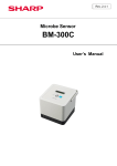
Handheld Laser Particle Counter
Model 3886 GEO –α
Operation Manual
Please read this manual carefully and understand the warnings
described in this manual before operation.
Kanomax Japan Inc.
.
Please keep this manual handy for future reference.
02001
06.08
Thank you for purchasing a product of Kanomax, Inc.
Please read this operation manual carefully and operate the instrument properly
by following the instructions given in this manual.
Important safety Information
Danger: For prevention of accidents resulting in injury or death
Items under this heading show measures to prevent serious injury or death, which may result if the instructions in this
manual are not observed and the instrument is operated inappropriately.
Caution: For prevention of the damage of product
Items under this heading show measures to prevent damage to the product and conditions that affect our product
warranty.
[Definition of Signs]
This symbol indicates a condition (including danger) that requires caution.
The subject of each caution is illustrated inside the triangle (e.g., high temperature caution symbol
shown on the left).
This symbol indicates prohibition. Do not take a prohibited action shown inside or near this symbol
(e.g., disassembly prohibition symbol shown on the left).
This symbol indicates a mandatory action. A specific action is given near the symbol.
Danger
○ Do not disassemble or heat the batteries
… There is danger of explosion.
Explosive
Handle Properly
○ For AC power supply, do not use the AC adapter other than the one
supplied with the instrument.
… An inappropriate adapter may damage the instrument.
… It may generate heat and cause fire.
i
Forbidden
Danger
○
Never disassemble, modify or repair the instrument and its accessories.
… This instrument uses a Class 3B laser diode as the light source.
Exposure to the laser may cause loss of eyesight and other injury.
… Disassembly may cause short circuit and/or other failure.
○ Never bring the probe close to a
flammable gas atmosphere.
… The heated sensor may cause fire or
explosion.
Do not use near
Flammable gas
○ Never touch the sensor
… The sensor is heated during operation.
Touching the heated sensor may cause
burns, and may also damage the sensor
itself.
Hot surface
Don’t touch
Caution
○ Do not use or leave the instrument in a high
temperature/ humidity environment, or in a
dusty environment.
Do not leave the instrument under direct
sunlight for a prolonged period.
… This instrument may not function properly
outside of the operating temperature range.
Forbidden Use
○ Do not apply strong shock or place/drop
anything heavy on the instrument.
… Failure to observe the above may cause
damage or malfunction to the instrument
Forbidden
ii
Caution
+
○ Set the batteries in the correct direction
… Setting the batteries in the wrong direction may cause
leakage, leading to contamination of the instrument and
Insert correctly
surroundings.
−
○ Do not wipe the body with solvent
… The body may deform or deteriorate. Use soft dry cloth to remove stains.
If stains persist, soak the cloth in a neutral detergent and wipe the
instrument with a soft cloth.
Do not use volatile solvents such as thinner and benzine.
Forbidden
○ Do not use the instrument near equipment emitting high radiation noise.
… The instrument may malfunction due to the noise. The Air velocity sensor is
especially sensitive to radiation noise.
○ Connect the AC adapter to a power source with minimum noise.
Handle Properly
… The noise may cause malfunctioning.
○ Do not pull the probe cable strongly, or suspend the unit by
holding the cable.
… It may cause malfunctioning and breaking of the wire.
○ Do not use the instrument in a water vapor atmosphere.
Forbidden
Water Drops
… The heat dissipation rate will change, preventing
correct measurement.
It may also damage the sensor.
Forbidden
Force
○ Do not apply strong force to the sensor
… Deformation of the sensor will prevent accurate
measurement. It may also break the wire of the
Forbidden
sensor.
※Air Velocity probe and Temp.& Humidity probe are options (sold separately)
iii
SAFTY OF LASER PRODUCTS
Model 3886 GEO-α is Class 1 LASER PRODUCT.
CLASS 1 LASER PRODUCT
INVISIBLE LASER RADIATION WHEN
OPEN DO NOT STRATE INTO BEAM OR
VIEW DIRECTLY WITH OPTICAL
INSTRUMENTS
This instrument is classified into the class 1 laser product as defined by safety of the laser product
JIS C 6802(IEC 60825-1).
Never, decompose this instrument to preventive exposed you to the laser radiation.
iv
Table of Contents
1. Check of Components.................................................................................................................... 1
1.1 Standard accessories.................................................................................................................................... 1
1.2 Options............................................................................................................................................................ 1
2. Description of Components........................................................................................................... 2
2.1
2.2
2.3
2.4
Front.............................................................................................................................................................. 2
Rear.............................................................................................................................................................. 2
Side............................................................................................................................................................... 3
Top ................................................................................................................................................................ 3
3. Handling & Cautions ....................................................................................................................... 4
3.1
3.2
3.3
3.4
3.5
Power supply................................................................................................................................................ 4
Turning the power on................................................................................................................................... 5
Cautions before starting the measurements.............................................................................................. 6
After the measurement................................................................................................................................ 7
Measurements using optional probes (Temperature & Humidity, Air velocity)......................................... 8
4. Setting before Measurement ......................................................................................................... 9
4.1
4.2
4.3
4.4
4.5
Selection of measuring mode ..................................................................................................................... 9
Setting the measuring condition................................................................................................................ 11
Setting of Alarm level .................................................................................................................................13
Selection of option and units .....................................................................................................................14
Calendar and computer communication setting......................................................................................14
5. Measurement Method ................................................................................................................... 15
5.1
5.2
5.3
5.4
5.5
5.6
Explanation of measurement screen........................................................................................................15
REPEAT Mode .........................................................................................................................................16
SINGLE mode ...........................................................................................................................................17
CONTINUOUS mode ...............................................................................................................................18
CALCULATION mode...............................................................................................................................19
REMOTE mode.........................................................................................................................................20
6. Data Processing............................................................................................................................. 21
6.1
6.2
6.3
6.4
6.5
Request for stored data in built-in memory… ..........................................................................................21
Display of stored data on the screen… ....................................................................................................21
Dump of stored data…..............................................................................................................................22
Printout of stored data…............................................................................................................................25
Deletion of stored data…...........................................................................................................................28
7. How to Use Option Probes........................................................................................................... 29
7.1
7.2
7.3
7.4
Option probes.............................................................................................................................................29
Installation of probes..................................................................................................................................29
Setting of display........................................................................................................................................30
Extension rod for air velocity probe...........................................................................................................30
8. Error Message................................................................................................................................ 31
9. Battery Check................................................................................................................................. 32
10. Specification................................................................................................................................. 33
11. Troubleshooting........................................................................................................................... 34
12. Warranty and After Service ........................................................................................................ 35
13. Contact Information .................................................................................................................... 36
1. Check of Components
When unpacking, check the contents in the box using the list below
1.1 Standard accessories
Name
Model No.
Functions
Filter
Model 3886-03
Used to clean the air flow route inside the instrument with clean air.
AC Adapter
Model 3886-01
Used for AC powered operation. To be used especially for
continuous measurements.
Ni-MH (Nickel
Metal Hydride)
Batteries
FNH HR AA 4BF
(Fuji Film Battery)
Used for battery powered operation.
*The dedicated battery charger listed below must be used for
charging the batteries. The AC adapter cannot be used for
charging the batteries.
Quick Charger
FNW 1 BX D
(Fuji Film Battery)
For charging the Ni-MH batteries. Charging time is approx. 260
minutes.
1.2 Options
Name
Temp. &
Humidity probe
Air Velocity probe
Extension rod for
air velocity probe
Printer
Printer cable
Model No.
Functions
Model 0842
For measuring temperature and humidity.
Model 0843
For measuring air velocity.
Model 0843-01
For measuring air velocity at high locations.
DPU-201GS
Model 3886-07
For direct printing of measured data.
For connecting the instrument and the printer.
For transferring data stored in the instrument to a PC, and remote
control of the instrument from the PC.
For connecting the instrument and the PC
For storing and carrying the instrument.
For fixing the instrument for a measurement.
Application soft
Model S388-61
RS-232C cable
Carrying Case
Tripod
Model 3886-08
Model 3886-02
1
2. Description of Components
Name and functions of each component are explained in this chapter.
2.1 Front
Inlet
Graphic LCD
START/STOP Key
SET Key
△(Up) Key
PREV Key
▽(Down) Key
POWER Switch
Name of component
Inlet
Graphic LCD
SET Key
PREV Key
POWER Switch
△(Up) Key
▽(Down) Key
START/STOP Key
Functions
Inlet for sampling air.
Displays measured data and status of operation.
To execute a specified item.
To return to the previous screen
To turn on/off the power
To set parameters and values.
To start/end a measurement.
2.2 Rear
Battery Box
2
2.3 Side
Power Inlet
Modular Port
Component
Modular Port
Power Inlet
Functions
Communication port to transfer data to a printer or PC.
Connection for the AC adapter.
2.4 Top
Temperature/Humidity (T/H)
Probe Terminal
Air Velocity
Probe Terminal
Inlet
Component
Inlet
Temperature/Humidity (T/H) Probe Terminal
Air Velocity Probe Terminal
Functions
Inlet for sampling air.
Connection for Temperature/Humidity probe.
Connection for air velocity probe.
3
3. Handling & Cautions
3.1 Power supply
Please use the supplied AC adapter and refrain from the battery operation for the long consecutive
measurements (more than 2 hours)
This instrument has the monitoring function of operating voltage, and battery alarm will be indicated
when the voltage goes down below the specified value.
If you leave the instrument in such a conditions for a few minutes, the power automatically goes off. In
some of measuring mode, the data of measurement in process will not be stored. (Please refer to
Chapter 8 for details)
If the alarm sign is shown, please stop the measurement and charge the batteries, or replace with the
charged batteries.
◆Use of AC Adapter
Insert the plug of the supplied AC adapter into the power inlet at the side of instrument.
The AC power should be in the range of 86-264V 50/60Hz. Do not use the AC power outside of this
range.
◆Use of Ni-MH Batteries
Prepare 4 pieces of Ni-MH batteries (1.2V, 2500mAh) and fully charge them. Charging time is approx.
260 minutes.
When charging is completed, put the batteries into the instrument in the correct directions.
Battery life is about 3 hours, but it will vary by the type and capacity of battery, or status of
charging. When optional Temp.&Humidity probe and Air velocity probe are used at the same
time, there will be the cases that operating hours will become less than 2 hours.
Figure: Direction of Inserting Batteries
※Though alkaline batteries can also be used, please note that the battery life for alkaline batteries will be
approx. 1.5 hours which is shorter than the Ni-MH batteries.
4
3.2 Turning the power on
(1)
Make sure to remove the cap of air inlet
at the top of the instrument.
(2)
Push POWER switch in the function
key. Initial display shows the mode and
setup data of previous measurement in
WAIT status (Set at SINGLE mode at
the time of delivery).
Please refer to Chapter 4 for the
customizing of measuring mode or
method.
(3)
WAIT sign will change to READY after
10 seconds. Then, measurement can be
started by pushing the START key.
At the time of delivery, sampling time
is set at 1 minute, so the measurement
will be automatically stopped after 1 minute.
[ Explanation of initial screen ]
Measuring mode
Status
Particle size (SMALL)
(1) Remove the cap!
(3) START/STOP key
(2) Push POWER switch.
Power on
SINGLE
WAIT 0.3
0.5
15:25
0.00E+0/cf
0.00E+0/cf
After 10 sec.
Current time
Number of counts or
concentration
Particle size (LARGE)
SINGLE 003BP 15:25
READY
0.3
0.00E+0/cf
0.5
0.00E+0/cf
START/STOP key
SINGLE 003BP 15:25
1:00 0.3 [測定終了]
0.00E+0/cf
0.5 0.00E+0/cf
[Measuring finish]
SINGLE 003BP 15:30
STOP 0.3 0.00E+0/cf
0.5 0.00E+0/cf
5
3.3 Cautions before starting the measurements
3.3.1 Location
This product is designed and produced for the operations in clean room environment. Please refrain
from using in the dressing room of clean suits, or in the ordinary environment (e.g. offices, turnery,
outdoors, smoking rooms etc.)
It will contaminate the internal components and increase the maintenance frequency.
3.3.2 Connection of sampling tube
Connect the sampling tube to air inlet for the collection of the air at distant place.
―Requirement for sampling tube ―
■Material
Material of tube should be metal (stainless, copper, alloy steel), glass or synthetic resin
which will not generate the plastic deposit.
■Length, Inner Diameter
Long or narrow sampling tube may be bent or pinched, causing pressure loss or clogging,
which will damage the vacuum pump and increase the maintenance frequency.
It also causes the deposit loss of particles and lowers the accuracy of measurements.
Length of sampling tube must be less than 1m and the inner diameter must be over 1/4 inch
(φ6.4mm).
■Pressure Loss
Large pressure loss will prevent the instrument to maintain the 0.1cfm (+/-10%) flow rate.
Pressure loss at sampling tube must be less than 1kPa (approx. 100mmH2O).
6
3.4 After the measurement
[Cleaning of internals]
Internals of the instrument may be contaminated after measurement.
Please carry out the following cleaning procedure after finishing the measurement.
−The method of cleaning and storage−
① Stop the measurement before cleaning
② Connect the filter to the air inlet at the top of the instrument, using the supplied tube.
* There is a possibility that the tube will be folded and inlet will be blocked when connecting
the tube to the inlet. Operation of the instrument in such a condition will overload the
vacuum pump and shorten the operating life.
③ Change UNIT to counts (CNT) and start the measurement
④ Finish the operation only after the confirmation that the count value gets stable and doesn’t
increase or decrease for more than 10 seconds.
⑤ Turn the power off and put the cap over the inlet
※ To prevent the contamination during storage, do not fail to cover the inlet by cap.
Caution
If cleaning is continued in a high concentration environment, the dust will accumulate on the filter and clog
the filter. In such case, the error indication (F) may be displayed indicating an insufficient flow volume.
In addition, this may lead to abnormal count with unstable readings as the particles accumulated on the
filter will flow in the instrument by vibrations.
7
3.5 Measurements using optional probes (Temperature & Humidity, Air velocity)
Wind direction mark
◆Air velocity probe
* When measuring, set wind direction mark against the wind direction.
* Check the tip of probe periodically to confirm that it is kept clean.
Dust attached to the sensor will affect the accuracy of the measurement.
Wind
―Cleaning of the air velocity probe―
◇ Rinse tip of probe in alcohol if sensor is oily, dry it in low wind.
◇ When you get rid of dust, blow them off by blow blush for camera or rinse in water and dry them
completely.
※ Turn off power when you wash sensor.
※ Do not dry probe with heat.
( Heat damages sensor and became impossible to restore. )
◆Temperature & Humidity probe
*As for measurements of air temperature, accurate value will not be given in the still air.
(Exempt from performance-guarantee range.)
You can get correct value in velocity of 0.1m/s or over. (Move probe slowly.)
*Response time in the air temperature measurement becomes quicker when the velocity is high.
For example, when air velocity is 1m/s the response time is 20 seconds. Please keep the data when
indications become stabile.
*The humidity measurement value might rise abnormally by the condensation of the humidity sensor.
In case of the measurement in rapid temperature change or long use in high humidity, keep probe for 24 hrs
in 40%RH or less and dry probe when wet.
―Humidity measurement … Comparison with ASSUMANN type psychrometer―
Because the humidity measurement function is strictly proofread using a standard humidity generation
device (two temperature difference method), you will find it is handy.
And, because a steady measurement can be done as an electronic hygrometer, this unit can take the place
of ASSUMANN type psychrometer.
When the comparison measurement is done between T/H probe and the ASSUMANN type psychrometer,
the ASSUMANN type psychrometer occasionally display high humidity.
Since handling conditions like dust, dew, or how to lap gaze can in flvence the result of ASSUMANN.
Therefore, it is necessary to be careful when you handle the ASSUMANN type psychrometer.
Please refer to Japan Industrial Standards concerning notice in the measurement with the ASSUMANN type
psychrometer etc. (JIS-Z8806 "Method of measuring humidity") etc.
8
4. Setting before Measurement
4.1 Selection of measuring mode
Power on
PREV
(1)
Push POWER key to input the power supply.
Then PREV key.
SINGLE
0.3/0.5µm
STR:N BEEP:N PR:N
SAMPLE 01:00
NO
PREV
(2) Push PREV key again to proceed to the setup screen
<MODE>
1.REPEAT
4.CALC
2.SINGLE
5.REMOTE
3.CONT
(3) Use △
△▽
▽ key to move the cursor, and push SET key to select
the mode you need.
SET
PREV
[1.REPEAT]
[2.SINGLE]
REPEAT
0.3/0.5µm
STR:N
BEEP:N
PR:N
SAMPLE 01:00
2TIMES
INT
00:05:00
NO
[3.CONT]
CONT
STR:N
SINGLE
STR:N
SAMPLE
0.3/0.5µm
BEEP:N
PR:N
01:00
NO
[4. CALC]
0.3/0.5µm
BEEP:N
PR:N
CALC
STR:N
SAMPLE
(4) Push PREV key to go back to
the MODE screen.
[5. REMOTE]
0.3/0.5µm
BEEP:N
PR:N
01:00
2TIMES
NO
9
REMOTE
0.3/0.5µm
BEEP:N
NO
Measuring
mode
Content of measurement
SAMPLE
TIME
INT
(Time
Setting)
(Frequency
Setting)
(Interval
Setting)
Repeat [5.2]
Measurement repeatedly
○
○
○
Single [5.3]
Measurement once
○
Once
○
Continuous
[5.4]
Continuous measurement;The measurement ends if
STOP is pushed.
It measures repeatedly, and mean value, a standard
deviation, the maximum value are calculated from data.
Only result is done and the store is not done in the data
store as for the store doing and each measurement
result.
Measurement by remote control from computer.
(The application software of the option is necessary)
−
−
−
○
○
−
−
−
−
Calculation
[5.5]
Remote
[5.6]
10
4.2 Setting the measuring condition
In the case of REPEAT mode (other mode even same)
<MODE>
1.REPEAT
4.CALC
2.SINGLE
5.REMOTE
3.CONT
Use the △
▽ key to move the cursor, and push the SET key to
select the mode you require.
△▽
PREV
SET
④Warning beep sound
① Measuring mode
REPEAT
0.3/0.5µm
STR:Y BEEP:N
PR:N
SAMPLE 10:00 30TIMES
INT 00:30:00
NO
③ Data storage
⑥ Sampling time
⑧ Interval
Name
①
Measuring mode
②
③
Particle size
Data storage
Warning
beep
sound
④
⑤
Data printing
⑥
⑦
⑧
Sampling time
Frequency
Interval
Confirmation
setup
⑨
of
② Particle size
⑤ Data printing
⑦ Frequency
⑨ Confirmation of setup
Explanation
Five kinds of REPEAT, SINGLE, CONT, CALC,
REMOTE
Two kinds selection from 0.3, 0.5, 1.0, 3.0, 5.0µm
Y:data stored
N:data not stored
Y:beep sounded
N:beep not sounded
Y:data printed after the measurement
N:data not printed (refer to 6.4)
1 second∼99 minites59 seconds
1∼99 times and continuous (CNT)
1second∼24 hours
NO:not confirmed
OK:confirmed. Press SET key to shift measurement screen.
SET
REPEAT
0.3/0.5µm
STR:N
BEEP:N
PR:N
SAMPLE 01:00
2TIMES
INT
00:05:00
NO
SET
(1) For change setting, push SET key to move the cursor.
REPEAT
0.3/0.5µm
STR:N
BEEP:N
PR:N
SAMPLE 01:00
2TIMES
INT
00:05:00
NO
11
SET
(2) Push SET key to the item you need to change.
REPEAT
0.3/0.5µm
STR:N
BEEP:N
PR:N
SAMPLE 01:00
2TIMES
INT
00:05:00
NO
△▽
(3) Use △
▽ key to change the setting condition.
REPEAT
0.3/0.5µm
STR:N
BEEP:Y
PR:N
SAMPLE 01:00
2TIMES
INT
00:05:00
NO
SET
REPEAT
0.3/0.5µm
STR:N
BEEP:Y
PR:N
SAMPLE 01:00
2TIMES
INT
00:05:00
NO
(4) If you finished your set up , push SET key to move the cursor to
the position of NO .
.
△▽
REPEAT
0.3/0.5µm
STR:N
BEEP:Y
PR:N
SAMPLE 01:00
2TIMES
INT
00:05:00
OK
(5) Change
NO to OK using △
▽ key.
SET
MEASURING
SAMPLE TIME
0:02:00
TOTAL TIME
0:06:00
OK
(6) Push SET key.
SET
REPEAT
WAIT
00/02
29B
20:32
0.3 0.00E+0/m3
0.5 0.00E+0/m3
(7) Push SET key to proceed to the measuring screen.
12
4.3 Setting of Alarm level
<MODE>
1.REPEAT
4.CALC
2.SINGLE
5.REMOTE
3.CONT
PREV
MODE
<MENU>
1. MODE
4.DATA
2. ALARM
5.UTILITY
3. UNIT
△、▽
When PREV key is pushed at <MODE> screen, the screen will switch to
the <menu> screen.
1.MODE
・・・・・・ Selection of measurement mode and setup of
parameter
2.ALARM ・・・・・ Setup of alarm level
3. UNIT ・・・・・・・・・ Selection of optional probe and unit
4. DATA ・・・・・・・・ Request for stored data in built-in memory
5. UTILITY ・・・・・・ Calendar and computer communication setting
SET
<ALARM>
1. SMALL
0.00E+0
2. LARGE
0.00E+0
3. TEMP
12.5-30.0
In case the particle concentration exceed the acceptable level, or
temperature,
Relative humidity or air velocity go out of the specified range, this unit
can notify the occurrence of these alarm situation.
This menu is to preset the alarm level.
If SET key is pushed when the cursor is here, it moves to the following
page.
4. HUMI
5. VEL
<ALARM>
30.0-60.0
0.10-0.85
△
▽ key
SET key
PREV
1
SMALL
Small particle
2
LARGE
Large particle
3
TEMP
Temperature
4
HUMI
Humidity
5
VEL
Air velocity
*:Selected unit (refer to 4.4)
Adjust the value
Move the cursor
key
Go back to MENU after the setup
Lower bound Upper bound
−
○
−
○
○
○
○
○
○
○
unit
*
*
*
%RH
*
Setting range
0∼7.00E+7
0∼7.00E+7
0∼122.0
0∼100.0
0∼200.0
To activate the alarm buzzer, change the “BEEP: N” to “BEEP: Y” on the setup screen of the measurement mode.
When the sampling time has expired, the measured value will be compared with the setting range, and the
measured value will blink if it is out of the setting range.
Once you have an alarm condition, the alarm will not be reset unit the data of the following measurement falls in
the setting range.
When the unit of particle data is set to “COUNT”, the reading will blink at the time the measured value exceeds the
setting range.
To stop the buzzer, push any key except the POWER key.
13
4.4 Selection of option and units
<MENU>
1. MODE
4.DATA
2. ALARM
5.UTILITY
3. UNIT
This menu is to select the optional probes and the units of particle,
Temperature and air velocity.
△、▽
SET
△
<UNIT>
PROBE SETTING
1. T/H PROBE SET
2. VEL PROBE SET
▽ key
SET key
PREV
1
2
Move the cursor
Shift the screen of the selected menu
key
T/H PROBE
VEL PROBE
Go back to MENU after the setup
T/H probe
Velocity probe
SET:use
SET:use
NO:not use
NO:not use
[unit setup]
<UNIT>
1. PTCL
/m3
2.TEMP
℃
3. VEL
m/s
1.PTCL :particle ………… CNT:count, /m3:concentration in
1m3/cf:concentration in 1cf
2.TEMP :temperature ………… ℃, ゚ F
3.VEL
:air velocity ………… m/s, FPM
4.5 Calendar and computer communication setting
<UTILITY>
1. DATE
2005/03/28
2. TIME
14:25
3. ADDRESS 05
OK
<UTILITY>
4. COMMUNICATION
RS232C
1
2
DATE
TIME
3
ADDRESS
4
COMMUNICATION
△
▽ key
SET key
PREV
Year/ Month/ Date
Time
Address computer communication
through RS-485terminal
Communication with PC
Adjust the value
Move the cursor
key
14
Go back to MENU after the setup
5. Measurement Method
5.1 Explanation of measurement screen
③ Warning beep sound
⑤ Error message
②Number of data records
④Data printing
⑥ Current time
① Measuring mode
⑧Status of measurement
⑨ Sampling number
⑭ Temperature data
REPEAT 003BPM 15:25□
WAIT
0.3 0.00E+0/cf
01/06 0.5 0.00E+0/cf
25.5℃ 56.0% 0.25m/s
⑫ LARGE particle size
2
3
4
5
6
7
8
9
10
11
12
13
14
15
16
⑪ SMALL data
⑬ LARGE data
⑯ Air velocity data
⑮ Humidity data
⑩ SMALL particle size
Name
1
⑦ Error message
Explanation
Five kinds of REPEAT, SINGLE, CONT, CALC,
Measuring mode
REMOTE
003: Storage No. No display : No data records
Number of data records
(e.g. 003: three data records)
Warning beep sound
B: Beep sounded
Display no: Beep not sounded
Data printing
P: Data printed
Display no: Data not printed (refer to 6.4)
M: The buffer memory is over loaded when printing the data
Error message
(refer to 8)
Current time
Refer to 4.5
F: Flow error
L: Laser error
Error message
O:Maximum concentration is exceeded (refer to 8)
WAIT: Starting up
READY: Ready for measurement
Status of measurement
STOP: Measurement finished (refer to 5.2-5.6)
Tag number of the current measurement/ the specified sampling
Sampling time
frequency.
SMALL particle size
Smaller of 2 particle sizes chose at setup screen.
The number of counts or concentration of the particle size on 10.
SMALL data
(refer to 4.4)
LARGE particle size
Lager of 2 particle sizes chose at setup screen.
The number of counts or concentration of the particle size on 10.
LARGE data
(refer to 4.4)
Show the data by selected the T/H probe uses (refer to 4.4)
Temperature data
Show the data by selected the T/H probe uses (refer to 4.4)
Humidity data
Show the data by selected the Air velocity probe uses (refer to
Air velocity data
4.4)
15
5.2 REPEAT Mode
By setting the sampling time, frequency and interval of each measurement, this unit automatically measures as
specified and stops after measurements. Interval is the time between the beginning of first measurement and the
next. The setting of the particle size (um), data storage (STR), alarm (BEEP) and printout (PR) are possible.
Display screen
<MODE>
1. REPEAT
4.CALC
2. SINGLE
5.REMOTE
3. CONT
REPEAT
0.3/0.5µm
STR:Y BEEP:N
PR:N
SAMPLE 10:00 30TIMES
INT 00:30:00
OK
MEASURING
SAMPLE TIME
5:00:00 ← ①
TOTAL TIME 14:40:00← ②
OK
Operation
key
POWER
PREV
△
△
△
Operation explanation
Push POWER key to input the power supply.
Push PREV key twice to proceed MODE screen
▽ SET
Select 1.REPEAT
▽ SET
■Setup the particle size, requirement of data
storage , alarm , printout, sampling time,
frequency and interval of measurement.
Use △ ▽ key to change the setting condition,
then push SET key.
After the input is done, change NO to OK
and push SET key.
▽ SET
①:sum total of sampling time
②:total length of time from the beginning to
the end of measurement
After confirming these TIMEs, change NO to OK and
push SET key.
REPEAT 003BPM 15:25
WAIT 0.3 0.00E+0/cf
01/30 0.5 0.00E+0/cf
WAIT Mode
WAIT sign is shown for the stabilization of internal
pump.
REPEAT 003BPM 15:25
READY 0.3 0.00E+0/cf
01/30 0.5 0.00E+0/cf
READY Mode
WAIT sign turns to READY in 10 seconds and
measurement can be started.
REPEAT 004BPM 15:25
③ → 09:59 0.3 0.00E+0/cf
④ → 01/30 0.5 0.00E+0/cf
START/STOP
NEXT
004BPM 15:35
⑤ → 15:55 0.3 0.00E+0/cf
02/30 0.5 0.00E+0/cf
Interval menu
REPEAT 004BPM 15:55
09:59
0.3 0.00E+0/cf
02/30 0.5 0.00E+0/cf
Measuring
16
Push START/STOP key to start the measurement.
The display shows the real-time data.
③: remaining time of each measurements
④: measurement number
Screen changes to interval mode after the sampling
time are over.
⑤: starting time of next measurement
Measurement is automatically started from the
indicated starting time.
★ The data is printed after the sampling time is over if
you chose printout. (refer to 6.4)
★ To stop the measurement halfway
Push START/STOP key.
Only the data of finished previous
measurement before pushing the STOP key
will be stored if you chose data storage
5.3 SINGLE Mode
By setting the sampling time, this unit automatically stops after the specified time.
The setting of the particle size (um), data storage (STR), alarm (BEEP) and printout (PR) are possible.
Display screen
<MODE>
1. REPEAT
4.CALC
2. SINGLE
5.REMOTE
3. CONT
SINGLE
0.3/0.5µm
STR:Y BEEP:N
PR:N
SAMPLE 10:00
OK
SINGLE 003BPM 15:25
WAIT 0.3 0.00E+0/cf
0.5 0.00E+0/cf
Operation key
△
△
Operation explanation
POWER
Push POWER key to input the power supply.
PREV
Push PREV key twice to proceed MODE screen
▽
▽
SET
Select 2. SINGLE
SET
■Setup the particle size, requirement of data
storage , alarm , printout, sampling time.
Use △ ▽ key to change the setting
condition, then push SET key.
After the input is done, change NO to OK
and push SET key.
WAIT Mode
WAIT sign is shown for the stabilization of
internal pump.
The particle size can be switched with the △
▽
key on the measurement screen.
3
SINGLE 003BPM 15:25
READY 0.3 0.00E+0/cf
0.5 0.00E+0/cf
SINGLE 004BPM 15:25
⑥→
09:59 0.3 0.00E+0/cf
0.5 0.00E+0/cf
SINGLE 004BPM 15:35
STOP 0.3 0.00E+0/cf
0.5 0.00E+0/cf
UNIT: [CNT] [/m ] [/cf]
READY Mode
START/STOP
INTERVAL menu
17
WAIT sign turns to READY in 10 seconds and
measurement can be started.
Push START/STOP key to start the
measurement
The display shows the real-time data.
Remaining time of each measurements
⑥:measurement number
Screen changes to interval menu after the
sampling time are over.
★ The data is printed after the sampling time is
over if you chose printout. (refer to 6.4)
★ To stop the measurement halfway
Push START/STOP key.
Only the data of finished previous
measurement before pushing the STOP
key will be stored if you chose data storage
5.4 CONTINUOUS Mode
It is a mode not to set the sample time, and nor to begin, and to end the measurement with the START/STOP key.
Particle size(µm)、data store(STR)、Warning(BEEP)、Printer(PR) can be set.
Operation
key
Display screen
<MODE>
1. REPEAT
4.CALC
2. SINGLE
5.REMOTE
3. CONT
CONT
STR:Y
0.3/0.5µm
BEEP:N
PR:N
POWER
Push POWER key to input the power supply.
PREV
Push PREV key twice to proceed MODE screen
△
△
▽ set
Select 3. CONT
▽ set
■ Setup the particle size, requirement of data
storage , alarm , printout.
Use △ ▽ key to change the setting
Condition, then push SET key.
After the input is done, change NO to OK
and push SET key.
OK
CONT
003BPM 15:25
WAIT 0.3 0.00E+0/cf
01/06 0.5 0.00E+0/cf
Operation explanation
WAIT sign is shown for the stabilization of internal
pump
WAIT Mode
The particle size can be switched with the △
CONT
003BPM 15:25
READY 0.3 0.00E+0/cf
01/06 0.5 0.00E+0/cf
CONT
004BPM 15:25
⑦ → 00:01 0.3 0.00E+0/cf
0.5 0.00E+0/cf
CONT
STOP
⑧ → 32:48
004BPM 15:58
0.3 0.00E+0/cf
0.5 0.00E+0/cf
▽
key on the measurement screen.
UNIT: [CNT] [/m3] [/cf]
READY Mode
WAIT sign turns to READY in 10 seconds and
measurement can be started.
Push START/STOP key to start the measurement
START/STOP
The display shows the real-time data.
Remaining time of each measurements
⑦:Measurement time(Count up)
★
01h00m
and the display change into the
following of 59:59 (It is 59second of 59 minutes.)
START/STOP
START/STOP key is pushed, and the
measurement is ended.
⑧:Measurement time
★ The data is printed after the sampling time is
Over if you chose printout. (refer to 6.4)
18
5.5 CALCULATION Mode
It is a mode by which measures repeatedly, and mean value from the measurement data, a standard deviation, the maximum
value, and minimum value are calculated. Only result is preserved, and each measurement result is not preserved in the data
store. The measurement frequency can be set at the grain size, the data store, warning, the printer, and the sample time.
Display screen
<MODE>
1. REPEAT
4.CALC
2. SINGLE
5.REMOTE
3. CONT
CALC
0.3/0.5µm
STR:Y BEEP:N
PR:N
SAMPLE 10:00 06TIMES
OK
CALC
003BPM 15:25
WAIT 0.3 0.00E+0/cf
01/06 0.5 0.00E+0/cf
CALC
003BPM 15:25
READY 0.3 0.00E+0/cf
01/06 0.5 0.00E+0/cf
⑧ →CALC
004BPM 15:25
⑨ →09:59 0.3 0.00E+0/cf
01/06 0.5 0.00E+0/cf
CALC AVE 0.00E+/cf
0.3µm S.D 0.00E+0/cf
06T
MAX 0.00E+0/cf
MIN 0.00E+0/cf
CALC AVE 0.00E+/cf
0.5µm S.D
0.00E+/cf
0.6T MAX 0.00E+0/cf
MIX 0.00E+0 / cf
CALC
0.3/0.5µm
STR:Y BEEP:N
PR:N
SAMPLE 10:00 06TIMES
OK
Operation
key
Operation explanation
POWER
Push POWER key to input the power supply.
PREV
Push PREV key twice to proceed MODE screen
△
△
▽ SET
Select 4. CALC
▽ SET
■ Setup the particle size, requirement of data
storage , alarm , printout, sampling time,
frequency.
Use △ ▽ key to change the setting
Condition, then push SET key.
After the input is done, change NO to OK
and push SET key.
WAIT Mode
READY Mode
START/STOP
WAIT sign is shown for the stabilization of internal pump
WAIT sign turns to READY in 10 seconds and
measurement can be started.
Push START/STOP key to start the measurement
The display shows the real-time data.
Remaining time of each measurements
⑧:The sample time of the remainder is
displayed.
⑨:Present measurement frequency
The last measurement data is maintained on the screen
for five seconds though the following measurement
begins at the same time as ending measuring time.
After the last data is displayed for five seconds, result is
displayed when the set measurement frequency ends.
The data of the small<SMALL> particle is displayed first .
It is possible to switch with the data of the
large<LARGE> particle in the SET key.
★ Data changes in order saying the
temperature, humidity, Air velocity , the
small particle, and the large particle
whenever the SET key is pushed when the
temperature humidity and Air velocity probe
are used.
Display of
result.
SET
It returns to measuring the set screen with the
PREV key.
★ When the measurement ends when setting the
printer is Y, the result is printed at once .(refer to 6.4)
★ When the START STOP key is pushed while
measuring, the measurement is stopped,
and the measurement data of times ahead of
that is used and operated.
PREV
19
5.6 REMOTE Mode
From computer to measurement mode by remote control
(The application software of the option is necessary.)
The connection method with the computer is the same method as forwarding the record data. (Refer to 6.3)
Display screen
Operation key
<MODE>
1.REPEAT
4.CALC
2.SING
5.REMOTE
3.CONT
POWER
Push POWER key to input the power supply.
PREV
Push PREV key twice to proceed MODE screen
△
REMOTE
0.3/0.5µm
BEEP:N
Operation explanation
△
▽
▽
SET
Select 5. REMOTE
SET
■ Setup the particle size, alarm ,.
Use △ ▽ key to change the setting
Condition, then push SET key.
After the input is done, change NO to OK
and push SET key.
OK
REMOTE
B
15:25
0.3 0.00E+0/cf
0.5 0.00E+0/cf
25.5℃ 56.0% 0.25m/s
The measurement begins automatically when the
application software is operated.
20
6. Data Processing
6.1 Request for stored data in built-in memory… <4.DATA>
<DATA>
STORE □□□
1.DISPLAY
3.PRINT
2.DUMP
4.CLEAR
Maximum 500 data can be stored, but the one measurement of CALC
mode is regarded as 4 data. For example, if the first data is stored at
number 016, next one is stored at number 020.
STORE □□□
Indicates the current total number of
stored data
1
DISPLAY
Display of stored data on the screen
2
DUMP
Dump of stored data
3
PRINT
Printout of stored data
4
CLEAR
Delete of stored data
▽ key
Move the cursor
△
Shift the setting screen of the selected
function
SET key
PREV
key
Go back to MENU after the set up
6.2 Display of stored data on the screen… <4.DATA>→<1.DISPLAY>
<DISPLAY>
STORE 139
START 001
STORE 001
0.3µm 0.00E+0 /cf
0.5µm 0.00E+0 /cf
STORE 001
1µm 0.00E+0 /cf
3µm 0.00E+0 /cf
5µm 0.00E+0 /cf
△
▽ key
SET key
Adjust the value
Move the cursor
START/STOP key
Shift the data display screen
PREV
Go back to DATA
key
Push START/STOP key to display the selected data
△
▽ key
SET key
PREV
21
key
Shift the previous/subsequent stored
data
Shift the other data of the same
stored data
Go back to Display
6.3 Dump of stored data… <4.DATA>→<2.DUMP>
Modular jack
<DUMP>
STORE 139
1. START
001
2. END
139
Start transmitting
Put the optional RS-232C cable into the modular jack of GEO-α,
and connect the other end of the cable with the PC to transfer
the stored data.
Do the communication setting of the PC and make the
condition that the PC can readout the data.
1
START
2
END
△
▽ key
SET key
The first tag number of the stored data
to be transmitted
The last tag number of the stored data
to be transmitted
Adjust the value
Move the cursor
START/STOP key
Start transmitting of the stored data
PREV
Go back to DATA
key
Required Items
- Computer
- Application software, Model S388-61 (Optional): Measurement software
- RS-232C cable, Model 3886-08 (Optional): Communication cable for connecting GEO-α and PC
Setting up the computer
Function
Word length
Parity bit
Set parity
Baud rate
GEO-α Setting
8 bit
None
Odd number
9600
Signal cable
GEO-α
Pin number
Signal name
1
TXD
3
RXD
5
CTS
6
GND
Connection
22
Computer (D-sub 9 pin)
Pin number
Signal name
2
RXD
3
TXD
7
RTS
5
GND
4
DTR
6
DSR
◆Forwarding data format
(1) Repeat, Single, Continuous mode
Format
999 crlf
9 crlf
99,99,99 crlf
99,99,99 crlf
99,99,99 crlf
xxx crlf
x crlf
xxx crlf
x,x,x crlf
Byte
5
3
10
10
10
5
4
5
7
Explanation
Store No
Measurement mode (1:Repeat、2:Single、3:Continuous)
Measurement start date
Measurement start time
Sampling time(hours, minutes, seconds)
Particle unit ( CNT , /cf , /m3 )
Temperature unit ( C , F )
Air velocity unit ( m/s , FPM )
Error message
(L:Light source, F:Flow rate, O:Over the maximum concentration)
Count data of 0.3µm, 90999E+99crlf using /cf or /m3 as unit
Count data of 0.5µm, 90999E+99crlf using /cf or /m3 as unit
Count data of 1µm, 90999E+99crlf using /cf or /m3 as unit
Count data of 3µm, 90999E+99crlf using /cf or /m3 as unit
Count data of 5µm, 90999E+99crlf using /cf or /m3 as unit
Temperature data
Humidity data
Air velocity data, 999.9 crlf using FPT as unit
999999999 crlf
11
999999999 crlf
11
999999999 crlf
11
999999999 crlf
11
999999999 crlf
11
*999.9 crlf
7
*999.9 crlf
7
*9.999 crlf
7
Total
135
*)
・T./H or Air velocity probe is not selected it becomes “ ***** crlf”.
・It becomes “###.#” when the value of T/H probe exceeds measurement range.
・It becomes “###.#” using m/s as unit (when the value of Air velocity probe exceeds measurement
range.)
Using FRM as unit, it becomes “###. #”.
23
(2) Calculation mode
Format
999 crlf
9 crlf
99,99,99 crlf
99,99,99 crlf
99999 crlf
99,99,99 crlf
xxx crlf
x crlf
xxx crlf
x,x,x crlf
9.999E+99,
9.999E+99,
999999999,
999999999 crlf
9.999E+99,
9.999E+99,
999999999,
999999999 crlf
9.999E+99,
9.999E+99,
999999999,
999999999 crlf
9.999E+99,
9.999E+99,
999999999,
999999999 crlf
9.999E+99,
9.999E+99,
999999999,
999999999 crlf
999.9,
999.9,
999.9,
999.9 crlf
999.9,
999.9,
999.9,
999.9 crlf
9.999,
9.999,
9.999,
9.999 crlf
Total
Byte
5
3
10
10
7
10
5
4
5
7
10
10
10
11
10
10
10
11
10
10
10
11
10
10
10
11
10
10
10
11
6
6
6
7
6
6
6
7
6
6
6
7
346
Explanation
Store No
Measurement mode (4:Calculation)
Measurement start date
Measurement start time
Measurement number
Sampling time(hours, minutes, seconds)
Particle unit( CNT , /cf , /m3)
Temperature unit( C , F )
Air velocity unit( m/s , FPM )
Error message
(L:Light source, F:Flow rate, O:Over the maximum concentration)
Average of 0.3µm
Standard deviation of 0.3µm
Maximum data of 0.3µm, 9.999E+99 crlf using /cf or /m3 as unit
Minimum data of 0.3µm, 9.999E+99 crlf using /cf or /m3 as unit
Average of 0.5m
Standard deviation of 0.5µm
Maximum data of 0.5µm, 9.999E+99 crlf using /cf or /m3 as unit
Minimum data of 0.5µm, 9.999E+99 crlf using /cf or /m3 as unit
Average of 1µm
Standard deviation of 1µm
Maximum data of 1µm, 9.999E+99 crlf using /cf or /m3 as unit
Minimum data of 1µm, 9.999E+99 crlf using /cf or /m3 as unit
Average of 3µm
Standard deviation of 3µm
Maximum data of 3µm, 9.999E+99 crlf using /cf or /m3 as unit
Minimum data of 3µm, 9.999E+99 crlf using /cf or /m3 as unit
Average of 5µm
Standard deviation of 5µm
Maximum data of 5µm, 9.999E+99 crlf using /cf or /m3 as unit
Minimum data of 5µm, 9.999E+99 crlf using /cf or /m3 as unit
Average of Temperature
Temperature data standard deviation
Maximum data of Temperature
Minimum data of Temperature
Average of Humidity
Standard deviation of Humidity
Maximum data of Humidity
Minimum data of Humidity data
Average of Air velocity 999.9 using FRM as unit
Standard deviation of Air velocity 999.9 using FRM as unit
Maximum data of Air velocity 999.9 using FRM as unit
Minimum data of Air velocity 999.9 using FRM as unit
*)
・T./H or Air velocity probe is not selected it becomes “ ***** crlf”.
・It becomes “###.#” when the value of T/H probe exceeds measurement range.
・It becomes “###.#” using m/s as unit
(when the value of Air velocity probe exceeds measurement range.)
24
6.4 Printout of stored data… <4.DATA>→<3.PRINT>
Modular jack
Put the optional Printer cable into the modular jack of GEO--α,
and connect other side of the cable with the Printer to print
the stored data.
<PRINT>
STORE 139
1. START
001
2. END
139
1
START
2
END
△
▽ key
The first tag number of the stored data
to be printed
The last tag number of the stored data
to be printed
Adjust the value
SET key
Start printing
Move the cursor
START/STOP key
Start printing of the stored data
PREV
Go back to DATA
key
Preparations
Printer (Option) ・・・・・・・・ Recommendatory Printer Model.
DPU-201GS (SEIKO CO., LTD),
Signal cable (Model 3886-07: Option), Signal cable connect GEO-α with Printer
DIP Switch Setting
Switch Number
SW1
SW2
SW3
SW4∼6
Baud rate
9600
Function
Word length
Parity bit
Set parity
Baud rate
GEO-α Setting
8 bit
None
Odd number
9600
Printer
ON
ON
ON
following table
SW4 Setting
OFF
SW5 Setting
OFF
SW6 Setting
ON
* When using DPU-H245, please use it with the manufacturers default setting.
Signal cable
GEO-α
Pin number
1
6
5
6
Signal name
TXD
GND
CTS
GND
Printer
Pin number
3
4
8
5
Signal name
DATA
GND
BUSY
GND
<<Caution>>
When the measurement interval (INT) in REPEAT mode is set at 15 seconds or less, there is a possibility
of Buffer error when printing is executed during a measurement. To print during a measurement, please
set the measurement interval over 15 seconds.
25
◆ Example of printout
(1) Repeat, Single, Continuous mode
2000/03/21 16:40:00
REPEAT
(3) During measurement
(Repeat, Single, Continuous mode)
E=
STORE 10 05:30
0.3um 564700 CNT
0.5um
10457 CNT
1.0um
323 CNT
3.0um
36 CNT
5.0um
8 CNT
23.2℃
45.7%RH
2000/03/21 16:40:00
E=LFO
REPEAT
05:30
1
0.3um 564700 CNT
0.5um
23.2℃
10457 CNT
45.7%RH
0.64m/S
Only two particle sizes are printed.
0.64m/S
26
(2) Calculation mode
(4) During measurement(Calculation mode)
2000/03/21 16:40:00
E=LFO
2000/03/21 16:40:00
CALCULATION
CALCULATION STORE 13 05:30
E=
05:30
10TIMES
10TIMES
0.3um AVE
6.66E+04 CNT
0.3um AVE
6.66E+04 CNT
STD
3.94E+03 CNT
STD
3.94E+03 CNT
MAX
71334 CNT
MAX
71334 CNT
MIN
60875 CNT
MIN
60875 CNT
0.5um AVE
2.78E+03 CNT
0.5um AVE
2.78E+03 CNT
STD
2.76E+02 CNT
STD
2.76E+02 CNT
MAX
3096 CNT
MAX
3096 CNT
MIN
2422 CNT
MIN
2422 CNT
1.0um AVE
9.83E+01 CNT
STD
3.90E+01 CNT
STD
0.3 ゚C
MAX
156 CNT
MAX
24.0 ゚C
MIN
23.2 ゚C
AVE
52.9 %RH
TEMP
AVE
23.5 ゚C
MIN
67 CNT
3.0um AVE
3.76E+00 CNT
STD
3.46E+00 CNT
STD
1.2 %RH
MAX
9 CNT
MAX
54.4 %RH
MIN
0 CNT
MIN
51.5 %RH
HUM
5.0um AVE
3.00E−01 CNT
AVE
0.20 m/S
STD
4.56E−01 CNT
STD
0.03 m/S
MAX
1 CNT
MAX
0.25 m/S
MIN
0 CNT
MIN
0.18 m/S
TEMP
HUM
VEL
AVE
VEL
23.5 ゚C
STD
0.3 ゚C
MAX
24.0 ゚C
MIN
23.2 ゚C
AVE
52.9 %RH
STD
1.2 %RH
MAX
54.4 %RH
MIN
51.5 %RH
AVE
0.20 m/S
STD
0.03 m/S
MAX
0.25 m/S
MIN
0.18 m/S
27
6.5 Deletion of stored data… <4.DATA>→<4. CLEAR >
<DATA CLEAR>
STORE 139
CLEAR YES
ALL the stored data will be deleted by executing this function.
YES:data deletion
CLEAR
△
▽ key
START/STOP key
PREV
key
28
NO:delete not
Adjust the value
Shift the data display screen
Go back to DATA
7. How to Use Option Probes
7.1 Option probes
Temperature/Humidity probe Model 0842
Air velocity probe Model 0843
7.2 Installation of probes
The T/H probe and Air Velocity probe must be inserted into “T/H” (refer to 2.4) and “VEL”, respectively, and the
lock screw cap must be provided.
Make sure to turn OFF the instrument before inserting and removing the probe.
GEO-α with the T/H probe and Air velocity probe installed
29
7.3 Setting of display
To provide the installation and display setting of each probe, please refer to 4.4.
To set the alarm, please refer to 4.3.
7.4 Extension rod for air velocity probe
When you want to measure the air velocity right under the filter which is located at a high position, extension rod
Model 0843-01 (optional) can be used. Insert the probe into the rod from the side of the sensor. When inserting,
please pay close attention not to touch the velocity sensor.
Extension rod for air velocity probe
30
8. Error Message
Error display location (L, F, O)
Error display location (M)
REPEAT 003BPM 15:25 L
WAIT 0.3 0.00E+0/cf
01/06 0.5 0.00E+0/cf
25.5℃ 56.0% 0.25m/s
Error message
Content of error
L
Laser Error
F
Flow Error
O
Maximum Concentration
Exceeded
M
Printer Buffer Exceeded
The error message will be displayed at the right of the
time display as shown left.
The initial letter of each error will be displayed according
to the priority order of errors. (Priority order: L→F→O)
Action
Failure of the laser luminescence part.
Please contact your local distributor or our service center for
information.
Displayed when the absorption flow rate is out of the specified range
of 2.83L/min ±10%.
If a filter or a tube is attached to the inlet of the instrument, please
remove it. If the “F” error sign still remains, it is a failure of the flow
route system including the pump.
Please contact your local distributor or our service center for
information. (Please refer to section 3.3.2.)
Displayed when the measurable concentration of the instrument is
exceed.
Please move to a cleaner place, or install the filter and measure.
If the “O” error sign still remains, please contact your local distributor
or our service center for information.
Displayed when the printer buffer is exceeded
Please note that once this error is displayed, the remaining data will
not be displayed.
<<Caution>>
When the measurement interval (INT) in REPEAT mode is set at 15 seconds or less, there is a
possibility of Buffer error when printing is executed during a measurement.
To print during a measurement, please set the measurement interval over 15 seconds.
31
9. Battery Check
BATTERY
REPEAT 003BPM 15:25
WAIT 0.3 0.00E+0/cf
01/06 0.5 0.00E+0/cf
25.5℃ 56.0% 0.25m/s
(1)First Alarm
When the battery voltage becomes less than 4.5 V, the message
"BATTERY" will be indicated at the top of the display (First Alarm). In approx.
5 minutes after the First Alarm, the display will switch to the following screen
(Second Alarm). When the Second Alarm is given, the pump, laser radiation
and software will stop, and the POWER key will become ineffective.
If the battery level becomes low during a measurement, the battery must be
replaced with an AC adapter. Power supply will automatically switch to AC
power supply when the AC adapter is inserted in the power inlet.
For continuous measurements for long periods, please use the AC adapter.
■ Please refer to the following table for the data storage conditions
when battery alarm is indicated.
While the First Alarm is displayed, data storage is possible.
BATTERY
Measurement
Mode
REPEAT
SINGLE
(2)Second Alarm
CONTINUOUS
CALCULATION
32
Data Storage
Every data measured before the Second Alarm will be
stored
If the measurement is finished before the Second
Alarm, the data will be stored.
Data will be stored if the "stop" key is pressed during
the First Alarm.
The calculation result which is provided based on the
data measured before the Second Alarm will be stored.
10. Specification
Measuring particle size
Light Source
Counting Efficiency
Zero Count
Coincidence Loss
Flow Rate
Sampling Time
Sampling Frequency
Mode of measurement
Display
Error sign
Interface
Communication protocol
Buffer Memory
Power supply
Operating hours
Dimensions
Weight
Environment operation
condition
Standard Accessories
Options
Temperature/Humidity Probe
0.3, 0.5, 1.0, 3.0, 5.0µm
Laser Diode
Meets JIS B9921
Meets JIS B9921
Less than 5% at 2,000,000 particles/cf
0.1 cfm (2.83 L/min)
1 second-99 minutes 59second (adjustable in second)
1-99 times, or Continuous
Single/Repeat/Continuous/Calculation
20 letters, 4lines LCD
Counts beyond max concentration, Drop of laser power,
Out of regulated flow rate (+/-10%), Low battery
RS-232C or RS-485 (Selectable on menu page), RJ-11 Connector N.B.
RS-485 is for cascade connection
Baud Rate 9600bps
500 data (In Calculation mode, 1 measurement is counted as 4 data)
4 pieces of AA-size Ni-MH batteries (1.2V-2.5Ah) or AC adapter (Input
100-240V). The batteries must be charged with the dedicated charger.
They cannot be charged with the AC adapter.
Max. 3 hours (By Ni-MH batteries)
115(W)×70(H)×211(D) mm
Approx. 980 g (without batteries)
Ambient temperature range:10-35℃
AC adapter, Filter, Tube, Handle, Operation manual
Printer, Printer cable, Temperature/Humidity probe, Air velocity probe,
Extension rod for Air velocity probe, Carrying case, Tripod, Application
software, RS-232C cable
Model 0842
Temperature range
Accuracy
Humidity range
Accuracy
Dimensions
0∼50℃(32∼122 ゚ F)
+/-0.5℃ (at over 0.2 m/s air velocity)
3-98%RH
+/-3%RH (+/-5% at the outside of 30-85%RH)
φ20×150mm
Air velocity Probe
Air velocity range
Accuracy
Dimension
Model 0843
0∼1m/s(0∼197FPM)
±0.05m/s(10FPM)
φ20×150 mm
Curl cord 0.2m(Max. extended length 1.5m)
Carrying case
Model 3886-02
Extension rod for air velocity probe
Model 0843-01
Application software
Model S388-61
33
11. Troubleshooting
Symptom
Possible Cause / Corrective Action
AC adapter is not inserted properly.
→ Confirm the AC adapter
The display does not appear even
Batteries level is low or empty
when the power is turned ON.
→ Replace the batteries, or
→ Charge the batteries (Ni-MH)
Measurement time with the Ni-MH Charging is insufficient → Charge the batteries
battery is short.
Battery deterioration → Replace with new Ni-MH batteries
Displayed reading blinks.
Alarm level is exceed → Change the alarm level setting.
Measurement data of the optional
Probe setting is not made → Provide the probe setting
probe cannot be displayed.
If display is ”WAIT” → Wait until the display changes to
“READY” , and press the
”START” key
Measurement does not start.
If display is “READY” → Press the “START” key
If display is “STOP” → Press the “START” key.
Wait until the display changes to
“READY”, and then press
the ”START” key again.
The
ambient
particle
concentration
is high.
The particle count or particle
→ Attach the filter to the inlet of the instrument.
concentration is high
The particle count or particle
Laser error or flow error. → Confirm the error status.
concentration is low
Flow error (F) is displayed when Filter is clogged. → Filter must be replaced with a new
internal cleaning is provided.
filter.
Reading is displayed as “##. #”
Displayed when measurable range is exceeded.
The wind mark of the probe is not faced against the wind
The velocity reading is low
direction.
Proper measurement cannot be done when there is no
The temperature reading is high
wind. Measurement must be performed where wind velocity
is over 0.1m/s.
・The setting of the BAUD rate is not correct.
Printing error
→ Confirm the setting of the printer.
・Improper cabling. (RS232C cable cannot be used.)
In “DUMP” mode, data cannot be ・The setting of the BAUD rate is not correct.
read.
→ Confirm the setting of the PC.
・Improper cabling (RS232C cable cannot be used.)
・The PC is not in a condition to take in data.
Incorrect data
Output format is not correct → Reset the format
34
Reference
3.1
3.1
4.3
4.4
4
8
3.4
3.5
3.5
6.4
6.3
6.3, 6.4
12. Warranty and After Service
Warranty
¾
A warranty card is not included in this product.
¾
The instrument (excluding consumables such as batteries) is warranted against defects in materials and
workmanship under normal use for a period of one year from the date of original purchase.
After Service
¾
When you have a problem with your unit, please check out the “Troubleshooting” section first.
¾
If that does not help, please contact your local distributor, or call our service center (See last page for contact
information).
¾
During the warranty period, we will repair at no charge a product that proves to be defective due to material
or workmanship under normal use. The limited warranty covers all defects encountered in normal use of the
product, and does not apply in cases such as; loss or damage to the product due to abuse, mishandling, or
alternation by the customer, or natural disaster. All return shipping charges are the responsibility of the
customer.
¾
Repair after warranty expiration:
Upon request, we will repair the instrument at the customer’s expense, if the instrument’s performance is
found to be recoverable by providing the repair.
¾
Replacement parts are available for a minimum period of five (5) years after termination of production. This
storage period of replacement parts is considered as the period during which we can provide repair service.
For further information, please contact our service center.
When making an inquiry, please provide the following information.
* Product Name: Handy Laser Particle Counter
* Model Number: xxxxxx
* Serial Number:
xxxxxx
* Date of Purchase: Day, Month and Year
* Description of Symptom in Detail:
35
13. Contact Information
U.S.A.
KANOMAX USA, INC.
PO Box 372, 219 Route 206, Andover, NJ 07821 U.S.A.
Tel: (800)-247-8887 / (973)-786-6386
FAX: (973)-786-7586
URL: http://www.kanomax-usa.com/
E-Mail: [email protected]
JAPAN
KANOMAX JAPAN, INC.
2-1 Shimizu Suita City, Osaka 565-0805, Japan
TEL: 81-6-6877-0183 FAX: 81-6-6879-2080
URL: http://www.kanomax.co.jp/
E-Mail: [email protected]
CHINA
Shenyang Kano Scientific Instrument Co., Ltd
No. 12, 4 Jia Wencui Road Heping District
Shenyang City PRC
TEL: 86-24-23845309 FAX: 86-24-23898417
URL: http://www.kanomax.com.cn/
E-mail: [email protected]
36