1
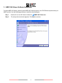
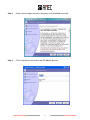
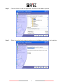
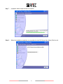
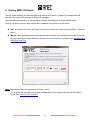
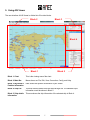
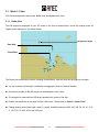
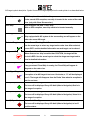
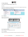
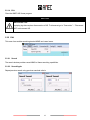
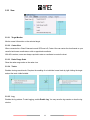
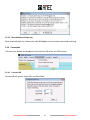
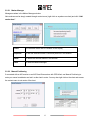
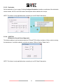
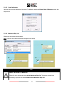
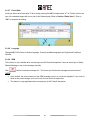
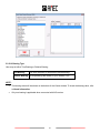
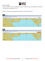
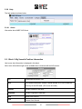
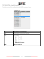
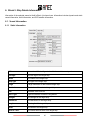
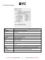
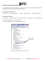
AIS Viewer for Receiver CYPHO-101 User Manual Version 1.03 Alltek Marine Electronics Corp 7F, No. 605, Ruei-Guang Road Neihu, Taipei, Taiwan 11492 TEL: +886 2 2627 1599 FAX: +886 2 2627 1600 Email: [email protected] Website: www.alltekmarine.com II COPYRIGHT The entire contents of this instruction manual, including any future updates, revisions, and modifications, shall remain the property of AMEC at all times. Unauthorized copies or reproduction of this manual, either in part or whole, in any form of print and electronic media, is prohibited. The contents herein can only be used for the intended purpose of this manual. DISCLAIMER AMEC is devoted to publish and maintain this product manual. As we continue to improve our AIS products to satisfy all customers’ needs, information in this document is subject to change without notice. AMEC does not make any representations or warranties (implied or otherwise) regarding the accuracy and completeness of this document and shall in no event be liable for any loss of profit or any commercial damage, including but not limited to special, incidental, consequential, or other damage. I Table of Contents I. COPYRIGHT & DISCLAIMER 1. What is the AMEC AIS Viewer? ................................................................................................... 1 2. System Requirement ................................................................................................................... 1 3. AMEC AIS Viewer Software Installation ..................................................................................... 2 4. Starting AMEC AIS Viewer........................................................................................................... 6 5. Using AIS Viewer ......................................................................................................................... 7 5.1. 5.2. 6. Block 1: Chart ............................................................................................................................... 8 5.1.1 Radar View ......................................................................................................................... 8 5.1.2 Alphanumeric View ........................................................................................................... 10 Block 2: Main Bar ....................................................................................................................... 12 5.2.1 File.................................................................................................................................... 12 5.2.2 Edit ................................................................................................................................... 13 5.2.3 View.................................................................................................................................. 14 5.2.4 Connection ....................................................................................................................... 15 5.2.5 Config ............................................................................................................................... 16 5.2.6 Help .................................................................................................................................. 23 5.3. Block 3: My Vessel’s Position Information ............................................................................... 23 5.4. Block 4: Ship Details Information ............................................................................................. 24 Block 5: Ship Details Information ............................................................................................. 25 6.1. 6.2. Vessel Information ..................................................................................................................... 25 6.1.1 Static Information .............................................................................................................. 25 6.1.2 Dynamic Information ......................................................................................................... 26 AtoN Information ........................................................................................................................ 27 Appendix How Determine Serial Port .............................................................................................. 28 II 1. What is the AMEC AIS Viewer? The AIS Viewer is a complementary charting software for the purchasing of AMEC AIS Receiver equipment. It operates mainly on Windows-based operating systems. User can use this software together with the AMEC class B AIS transponder to see the surrounding AIS traffics without connecting to a Chart Plotter device. However, the coastal map in AIS Viewer has limited details and the software itself should not be compared with a commercial ECS system. If user needs more complete functions, an advanced ECS or Chart Plotter device should be considered. When connected to an AMEC AIS receiver, AIS Viewer can provide listing and tracking on boats, chart marker editing tools, various viewing modes, and recording and replaying of AIS logs. The AIS Viewer is designed to work with AMEC AIS device, if user connects this AIS Viewer to non-AMEC AIS equipment, AMEC is not liable for any resulted incompatibilities. If you have any questions or comments for this AIS Viewer software, you are welcome to contact us at [email protected]. NOTICE RELIABLE VHF RECEPTION The AIS Viewer replies on the AIS messages received by the AIS device. Please ensure the AIS device has a good VHF reception for AIS messages. 2. System Requirement The minimum system requirements are: Operating System: Windows XP or above. CPU: 1GHZ. Memory: 128MB. Hard drive space: 100 MB. 1 3. AMEC AIS Viewer Software Installation To install AMEC AIS Viewer, please find the AMEC AIS Viewer program in the CD-ROM accompanied with your AMEC product. Use the following guidelines to install the viewer program. Step 1. Double click on the AIS Viewer installer file. Step 2. The setup welcome window appears. Click Next to continue. 2 AMEC AIS Viewer.exe Step 3. Please read and agree the license agreement, then click Next to proceed. Step 4. Fill the required user information and click Next to proceed. 3 Step 5. Choose a folder to install this application, and then click on Next to proceed. Step 6. Select your option for the shortcut preference and click Next to proceed with the installation. 4 Step 7. Installation takes couple seconds to complete. Step 8. When the installation completed, you may select to start AIS Viewer after clicking Finish to exit. 5 4. Starting AMEC AIS Viewer The AIS Viewer replies on the AIS messages received by the AIS device. Therefore it is essential the AIS device having a good VHF reception receiving AIS messages. When the application started, you are required to configure the settings for serial port and baud rate. You may use either manual or auto configuration to establish connection to the AIS device. Auto: the system will identify and show the serial port number and baud rate automatically.* (See note below) Manual: select appropriate serial port and baud rate manually. If the serial port is not listed, you may key in the serial port number directly. To determine the correct serial port, please refer to Appendix How Determine Serial Port. *Note: Some devices may not support auto connection setup. You may skip the connection setup using the Close button and configure later through AIS Viewer’s option. See Section 5.2.4 Connection. 6 5. Using AIS Viewer The user interface of AIS Viewer is divided into 5 function blocks. Block 2 Block 3 Block 4 Block 1 Block 5 Block 1: Chart This is the viewing area of the chart. Block 2: Main Bar Manus items are File, Edit, View, Connection, Config, and Help. Block 3: My Vessel’s Position Information Here shows the dynamic information of your vessel. Block 4: Ship List This area lists all vessels from the chart through AIS. The selected ship’s information would be shown in Block 5. Block 5: Ship details Information This area shows the ship information of the selected ship in Block 4. 7 5.1. Block 1: Chart AIS Viewer provides two chart modes: Radar View and Alphanumeric View. 5.1.1 Radar View The AIS targets are displayed on your PC screen in the form as shown below. Under this viewing mode, all targets will be displayed on the Radar display. Dangerous Target Own Ship* Friend Ship The Radar View shown above has the following characteristics: Each AIS ship has the shape of a triangle. You can manually set the ship’s coordinates or dragging the chart to a desired location. A maximum number of 500 AIS targets can be displayed on the viewer. The straight line extended from AIS target represents the course of the ship. Double click anywhere on the chart to make it the center*. Please refer to Section “Center View”. Change viewing scale (lower right corner) if needed. Available scales are 800, 400, 200, 96, 48, 24, 12, 6, 3, 1.5, 0.75, 0.5, 0.25, 0.125 and 0.05 (nm). 8 AIS target symbol description: Symbol for each AIS target displayed on the radar plotter is as described below. Own Ship GPS Reception: Normal / Color: Grey Under normal GPS reception, own ship is located in the center of the radar view. (only with Class B transceiver). Own Ship GPS Reception: No GPS / Color: Grey With no GPS reception, own ship needs to be located manually. AIS Target Color: Green Ship equipped with AIS system in the surrounding sea will appear on the radar view as an AIS target. Selected Target Color: Green / Flashing Black Frame Use the arrow keys to select any target on the radar view. After selected, press <ENT> and the detailed information on each target can be viewed. Dangerous Target Color: Red / Circled Frame When distance to a ship is smaller than CPA/TCPA, the target will be circled in RED. Use the arrow keys to select the dangerous target and to view its detailed information. Friend Ship Color: Magenta If any pre-stored Friend Ship is nearby, the Friend Ship will appear in Magenta on the radar view. Lost Signal Target Color: Green / Crossed If reception of an AIS target is lost over 10 minutes, a “X” will be displayed over it. The target will disappear from the Radar View when its reception is lost for one hour. AtoN (Real) Color: Green / Plus Sign The icon will be displayed if any AIS AtoN (Aids to Navigation) Real is in the range of reception. AtoN (Virtual) Color: Green / Plus Sign and Undercut The icon will be displayed if any AIS AtoN (Aids to Navigation) Virtual is in the range of reception. AtoN(Off position) Color: Red / Plus Sign The icon will be displayed if any AIS AtoN (Aids to Navigation) is in off position status. 9 SAR Color: Black The icon will be displayed if any air plane is in the range of reception. SART Color: Red / Cross The icon will be displayed if any SART message is sent out. Base Station Color: Green The icon will be displayed when any base station is in the range of AIS. Note: The straight line extended from the ship triangle symbol represents the course of the ship. 5.1.2 Alphanumeric View Under this mode, all ship details will be displayed alphanumerically. To browse the entire information, please use the scroll bar on the screen to navigate through table. MMSI Marine Mobile Service Identity CLASS AIS Message class types [A] Class A AIS [B] Class B AIS [N/A] Unknown [AtoN] Aids to Navigation RX COUNT The numbers of receiving messages MSG # The message ID should identify the message type NAME Ship Name CALL SIGN Ship’s Call Sign 10 RANGE The distance between target ships to own ship. The unit of range is “nm” (Nautical Mile). BEARING The relative angle between target ship and own ship. SOG Speed Over Ground, the unit of SOG is “kn” (knot). COG Course Over Ground HEADING The heading of the target ship. CPA Distance to Closest Point of Approach, the unit of CPA is “nm” (Nautical Miles) TCPA Time to Closest Point of Approach, the unit of TCPA is “min” (Minutes). LON Longitude of the target ship. LAT Latitude of the target ship. ROT Rate of Turn LENGTH The length of the target ship, the unit of LENGTH is “m” (meters). BEAM The beam of the target ship, the unit of BEAM is “m” (meters). DESTINATION The destination of the target ship. ETA Estimated Time of Arrival, (Month/Date/Hour/Minutes) SHIPTYPE Ship type of the target ship. CARGO Cargo information. 11 5.2. Block 2: Main Bar Holds File, Edit, View, Connection, Config, and Help menu items. 5.2.1 File The file menu item enables saving or replaying previous saved log files. Note, replaying the log data requires the disconnection of both AIS device and GPS receiver. Note that the right screenshot is during log playing mode. 5.2.1.1 Replay Log Replay a previously saved data Additional log operations during log playing. You may set preferences for auto log saving. Pause Play ll Pause log playing Stop Play ! Stop log playing 5.2.1.2 Export Current AIS Info Export the AIS data to a comma-separated value file format 5.2.1.3 Auto Saving Enable auto-saving function. User can set file path, time settings in the window (See screenshot below) 12 5.2.1.4 Exit Close the AMEC AIS Viewer program NOTICE REPLAYING LOG replaying log data requires disconnection of AIS. To disconnect go to “Connection”→ “Disconnect AIS” to disconnect AIS. 5.2.2 Edit This menu item enables searching desired MMSI and vessel name. 5.2.2.1 Search The search window provides vessel MMSI or Name searching capabilities. 5.2.2.2 Search Again Repeat previous search using previous searched criteria 13 5.2.3 View 5.2.3.1 Target Monitor Monitor vessel information on the selected target. 5.2.3.2 Center View When connected to a Class B transceiver and GPS went off, Center View can center the chart based on your vessel’s last known coordinates or with an appointed coordinate. With AIS receivers, users are always required to enter a coordinate to center the chart. 5.2.3.3 Radar Range Scale Show the radar range scale on the radar view. 5.2.3.4 Tracks Enables viewing vessel tracks. Requires the enabling of an individual vessel track by right clicking the target and set the track visible/invisible. 5.2.3.5 Log Enables the log window. To start logging, enable Enable Log. You may save the log session or clear the log window. 14 5.2.3.6 Show Monitored Ships only Show monitored ships only. Please refer to 4.2.5 Config for more information about ship monitoring. 5.2.4 Connection This menu item enables and disables the connection for AIS device and GPS receiver. 5.2.4.1 Connect AIS Connect AIS with specific “Serial Port” and “Baud Rate”. 15 5.2.4.2 Device Wizard Select appropriate serial port and baud rate for device connection 5.2.5 Config The configuration menu item provides preference settings. 16 5.2.5.1 Marker Manager Manages markers in the Marker Manager window. Note markers can be simply created through context menu (right click on anywhere on chart) and click “Add marker here” Locate The selected marker will be centered on the display Properties To edit the selected marker’s name and positions in this window. Delete To delete the selected marker in this window. Close To close the Marker Manager. 5.2.5.2 Manual Positioning If connected with an AIS receiver or an AIS Class B transceiver with GPS failed, use Manual Positioning to enter your vessel coordinates and set it as the chart’s center. You may also right click on the chart and access the context menu to set center of the chart. 17 5.2.5.3 Destination Set the destination of your voyage. Enabling Configure Destination checkbox, coordinates of the destination can be entered. Hit OK to save the location and the place will be marked with a red pin. NOTE: This feature is only applicable when connecting to an AIS Class B transceiver. 5.2.5.4 CPA/TCPA (Distance to Closest Point of Approach) This feature enables to set the desired values for CPA and TCPA collision avoidance. When a ship is entering the alerted area, it would be marked in red color on screen. (Refer to Section “Radar View”). NOTE: This feature is only applicable when connecting to an AIS Class B transceiver. 18 5.2.5.5 Chart Calibration User can fine tune the calibration of the chart. To calibrate, enable the Enable Chart Calibration button with adjustments. 5.2.5.6 Monitored Ship List Allows user to monitor selected ships. Note: user can view vessel information through cursor tooltip. HINT SELECT A VESSEL TO MONITOR Right click on a vessel and select Add to Monitored Ship list. To remove a vessel from monitoring, right click and select Remove from Monitored Ship List. 19 5.2.5.7 Friend Ship A ship can be set as a friend ship. To do it simply entering the MMSI number and a “Y”* at “Friend” column; the icon of the selected targets will turn to pink in the Radar display (Refer to Section “Radar View”). Click on “OK” to complete the setting. 5.2.5.8 Language Change AMEC AIS Viewer to another language. Currently available languages are English and Traditional Chinese. 5.2.5.9 SRM This function is only available when connecting to an AIS Class B transponder. User can select type of Safety Related Message or key in the message manually. Click button to send the message out*. The In-box and Out-box list message sent and received. *NOTE: Upon clicked, the device sends out the SRM message once in a minute as regulated. If you want to send out the next message, you have to wait for one minute of elapse time. This feature is only applicable when connecting to an AIS Class B transceiver. 20 5.2.5.10 Bearing Type User may set either True Bearing or Relative Bearing. True Bearing Use north direction to calculate all vessel bearings Relative Bearing All ship bearings are based on your vessel’s COG NOTE: The bearing status will be shown on the bottom of the Viewer window. To check the bearing value, refer to Vessel Information. Only true bearing is applicable when connected with AIS receiver 21 5.2.5.11 Tx On/Off This feature enables user to turn AIS transmission On/Off. The device will enter into Silent Mode. To restore the AIS transmission, simply select the Tx On. NOTE: This feature is only applicable when connecting to an AIS Class B transceiver. Tx On Tx Off 22 5.2.6 Help The help window is shown below. 5.2.6.1 About Information about AMEC AIS Viewer 5.3. Block 3: My Vessel’s Position Information User’s own ship information is displayed in this block. Note: some information might not be available when connected with an AIS receiver. UTC Coordinated Universal Time GPS GPS related information. Usually it would indicate 2D or 3D to show the accuracy of the GPS data. (3D is more accurate) Latitude Current Latitude of own ship. Longitude Current Longitude of own ship. SOG Speed Over Ground COG Course Over Ground 23 5.4. Block 4: Ship Details Information Received vessels and AtoNs are listed here by their MMSI, class type, and names. No. Order number of the received targets. MMSI Maritime Mobile Service Identity of the target. Class AIS class types [A] Class A AIS [B] Class B AIS [N/A] Unknown [AtoN] Aids to Navigation Name Name of the target ship. 24 6. Block 5: Ship Details Information Information of the selected vessel or AtoN in Block 4 is shown here. Information includes dynamic and static vessel information, AtoN information, and GPS satellite information. 6.1. Vessel Information 6.1.1 Static Information IMO International Marine Organization Number and its country code. Call Sign The call sign of the target ship. Name The name of the target ship. Ship Type The type of the target ship. Cargo Cargo information of the selected target ship. Destination Destination of the selected target ship. ETA Estimate Time of Arrival EPFS Type Type of Electronic Position Fixing device Draught The draught of the target ship. Dimension The dimension of the target ship. Length The length of the target ship. Beam The width of the target ship. Receive Time The latest received time of the target ship. 25 6.1.2 Dynamic Information MMSI Maritime Mobile Service Identity of the target ship and its country code. Nav. Status Navigational status of the target ship. ROT Rate of Turn Heading The direction of the target ship’s stem. Latitude Current latitude of target ship. Longitude Current longitude of target ship. COG Course Over Ground SOG Speed Over Ground Range Range between the selected target and own ship. Bearing The related position between own ship and target ship. The unit of bearing is degree(°). CPA Distance of Closest Point of Approach between own ship and target ship. TCPA Time to Closest Point of Approach between own ship and target ship. Pos.Accu Position Accuracy; related to the GPS device used. Received Time The latest received time of the target ship. 26 6.2. AtoN Information MMSI Maritime Mobile Service Identity of the AIS AtoN Name Name for the AIS AtoN Type Type of AIS AtoN Status Status of the AIS AtoN Dimension Dimension of the AIS AtoN EPFS Type Type of Electronic Position Fixing device Light Light of the lantern Latitude Current latitude of the AIS AtoN Longitude Current longitude of the AIS AtoN RACON Radar Beacon Pos. Acu. Position Accuracy; related to the GPS device used. 27 Appendix How Determine Serial Port If you PC/laptop does not have available serial port, you may use a RS232-to-USB adapter. To find out the proper serial port for connection use the following instructions. Windows 7 or VISTA version: Click on “Start” → Select “Control Panel” → Select “Device Manager” → Click Port (COM&LPT) Windows XP version: Click on “Start” → Select “My Computer” → Click “Control Panel” → Select “System” → Choose “Hardware” → Select “Device Manager” → Click Port (COM&LPT) In the example screenshot below, the serial port number is 30. Serial port number 28


![[1 ] Oracle® Enterprise Manager](http://vs1.manualzilla.com/store/data/005669073_1-0396df232df5e560fdd03210f5126330-150x150.png)