1
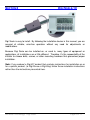
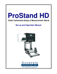
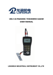
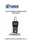
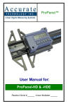
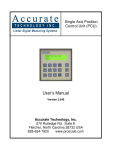
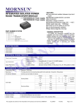
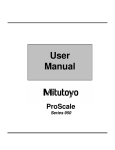
Digi Scale™
User Manual for:
Digi Scale Model 10 & Model 20
and all products with a Digi (white) Digital Readout
Firmware version P1.040 & Higher
Warranty
Accurate Technology, Inc., warrants this product against defective parts and
workmanship for 1 year commencing from the date of original purchase. Upon
notification of a defect, Accurate Technology, Inc., shall have the option to repair or
replace any defective part. Such services shall be the customer's sole and exclusive
remedy. Expenses incidental to repair, maintenance, or replacement under warranty,
including those for labor and material, shall be borne by Accurate Technology, Inc.
(Including freight or transportation charges during the first 30 days).
Except as expressly provided in this warranty, Accurate Technology, Inc., does not
make any warranties with respect to the product, either expressed or implied, including
implied warranties of merchantability or fitness for a particular purpose, except as
expressly provided in this agreement.
Accurate Technology, Inc., shall not be liable for any special, incidental, or
consequential damages or for loss, damage or expense directly or indirectly arising
from the customer's use of or inability to use the equipment either separately or in
combination with other equipment, or for personal injury or loss or destruction of other
property, or from any other cause.
To request repair work (either warranty qualified parts or not), contact Accurate
Technology, Inc. directly by phone, fax, or e-mail.
A Returned Merchandise
Authorization (RMA) number is required before returning a product for repair.
Accurate Technology, Inc.
+1 828.654.7920
800.233.0580
828.654.8824 (F)
www.digi-kit.com [email protected]
SAFETY WARNING
Before installing Digi Scale on any machinery:
Turn off the machine and disconnect the power.
SAFETY WARNING
P/N 800-1101-001. Rev. D Copyright
Accurate Technology Digi Scale
2003 All rights reserved
Page 2 of 17
Table of Contents
Section 1
General Information........................................................................................... 4
What This Manual Includes........................................................................................................... 4
About Digi Scale ........................................................................................................................... 4
Digi Scale Specifications ............................................................................................................... 4
Section 2
Digi Scale-10 ......................................................................................................... 5
Shortening Scales......................................................................................................................... 7
Section 3
Digi Scale-20 ........................................................................................................ 8
Section 4
Readout Operation ............................................................................................. 10
Readout Keys ............................................................................................................................. 10
Timing ........................................................................................................................................ 10
ON/OFF...................................................................................................................................... 10
MODE......................................................................................................................................... 10
+, 0, and – Keys.......................................................................................................................... 11
Changing Resolution .................................................................................................................. 11
Incremental Measurements ......................................................................................................... 11
Lock Mode .................................................................................................................................. 11
Reverse Scaling .......................................................................................................................... 12
Changing the Batteries ............................................................................................................... 12
Jumpers ..................................................................................................................................... 13
Frequently Asked Questions ....................................................................................................... 14
Accurate Technology Digi Scale
Page 3 of 17
SECTION 1
GENERAL INFORMATION
What This Manual Includes
This manual includes information for:
Digi Scale Model 10
Part Number:
Digi Scale Model 20
Part Number:
903-2006-001
903-2060-001
About Digi Scale
Digi Scales are a family of low cost measuring systems for applications requiring digital
precision and repeatability beyond a tape measure, but without the associated cost of
precision linear encoders.
While Digi Scale provides state of the art non-contact measuring at an affordable price,
it is not intended for the most demanding applications requiring robust electrical noise
immunity and the requirement to maintain a set position with power removed, such as
high power machinery applications. It is, however, well suited for most general purpose
measuring applications requiring digital precision, low cost, battery power, and reliable
operation. For more demanding applications Accurate Technology ProScale™ ABS
should be considered. Some differences are:
Feature
Digi Scale
ProScale ABS
Technology:
Incremental
Absolute
Measuring Range:
6 & 60 in.
10 in. to 20 ft.
Accuracy:
± .010 in.
± .002 in./ft
Repeatability:
± .010 in
± .001 in
Encoder length:
6 feet
up to 20 ft.
Programmable:
No
Yes
Data Output:
No
Yes
Power:
Battery
Battery or 24VDC
Applications:
General Purpose
General Purpose & Machinery
Warranty:
1 Year
3 Years
Digi Scale Specifications
Measuring Range:
Accuracy:
Resolution
Repeatability:
Readout Range:
Operating Temp:
Encoder:
Applications:
Warranty:
Model 10:
6 inches (150mm)
Model 20:
60 inches (1.5m)
+ .010inch
.01in/.1mm or .001in/.01mm or 1/16, 1/32, 1/64 inch
.01inch or .1mm
+ 999.999 in; + 99 63/64 in; + 9999.99 mm
32 to 120°F
6 foot (2m) six-conductor cable terminated by RJ12 connector.
Non-Machinery, Dry environment
One year from date of purchase.
Accurate Technology Digi Scale
Page 4 of 17
SECTION 2
DIGI SCALE-10
Digi Scale is easy to install. By following the installation basics in this manual, you are
assured of reliable, error-free operation without any need for adjustments or
modifications.
Because Digi Scale can be installed on, or used in, many types of equipment or
applications, all installations are a little different. Therefore, it's the responsibility of the
installer to choose bolts, screws, or other mounting hardware that guarantees proper
installation.
Note: If you ordered a Digi-Kit” product that contains instructions for installation on or
for a specific product, (ie Digi Fence or Digi Stop) follow those installation instructions
rather than the instructions presented here.
Accurate Technology Digi Scale
Page 5 of 17
1. Determine appropriate mounting locations. Place the Encoder in a location that
will allow the scale to be inserted into the Encoder and attached to the moving part
of the target device.
2. Fasten the Encoder using three screws (or bolts) to the target device. If the
surface is excessively uneven, you may need to use washers or spacers to ensure
a good mount.
Scale
Scale
Up
For
Positive
Readings
Scale
Down
For
Negative
Readings
Scale
Up
For
Negative
Readings
Scale
Down
For
Positive
Readings
Encoder
3. Note the orientation of the Encoder. When the side with two screw holes is on
the right, moving the scale up produces positive readings and moving the scale
down produces negative readings.
Scale:
Attached to moving part
Readhead
Encoder:
Attach to stationary
Digital Readout
Accurate Technology Digi Scale
Page 6 of 17
4. Check that the scale axis is aligned with the direction of motion of the moving
part.
5. Attach the scale to the moving part of the target device.
connections are secure or inaccurate scale readings can occur.
Be sure both
6. Take care when sliding the scale into the Encoder so the brass “fingers” inside
the Encoder do not get damaged. (A slight “wiggling” motion when installing the
scale into the Encoder will simplify the process.)
Note: If your application requires a scale of a different length, see SHORTENING
SCALES.
Accurate Technology Digi Scale
Page 7 of 17
Shortening Scales
To shorten Digi Scale follow these steps:
The scale has stainless-steel wires pressed into the side that could be damaged if not
cut properly.
1. Clamp the wires so they do not pull away from the extrusion.
2. Using a hacksaw, cut through the aluminum extrusion.
3. Use a file or sanding tool to chamfer the cut end to approximately the
specifications shown in the illustration.
4. Remove all burrs.
5. Test the shortened scale by sliding a Encoder on.
There should not be any
binding.
.07” (2mm)
.25” (6mm)
Wires
Accurate Technology Digi Scale
Wires
Page 8 of 17
SECTION 3
DIGI SCALE-20
Digi Scale is easy to install. By following the installation basics in this manual, you are
assured of reliable, error-free operation without any need for adjustments or
modifications.
Because Digi Scale can be installed on, or used in, many types of equipment or
applications, all installations are a little different. Therefore, it's the responsibility of the
installer to choose bolts, screws, or other mounting hardware that guarantees proper
installation.
Note: If you ordered a Digi-Kit” product that contains instructions for installation on or
for a specific product, (ie Digi Fence or Digi Stop) follow those installation instructions
rather than the instructions presented here.
1. Determine an appropriate mounting location for the Digi Scale. The scale should be
mounted to a stationary part of the device. The Encoder then slides along the scale,
using the supplied guide clip to transfer movement to the Encoder. The Readout
should be mounted in a location which allows for easy viewing by the operator. The
location of the parts should also safeguard the cable from possible damage.
2. Drill and countersink any necessary holes and mount the scale using M4 (or #8)
flathead screws. It may be necessary to use washers or spacers to ensure a good
mount if the scale is to be mounted on an uneven surface. Be sure the screw heads
do not protrude above the surface of the extrusion. If they do, they will interfere with
the Encoder.
Check that the scale is properly aligned with the direction of motion of the moving
part.
Accurate Technology Digi Scale
Page 9 of 17
3. Referring to the figure, note these two installation requirements:
a. For accurate measurements, the guide clip should be mounted perpendicular to
the direction of travel of the Encoder.
b. Over the full range of travel, the guide clip should exert some pressure on the
Encoder so the two move as a single unit.
Note: Failure to use guide clip could void the warranty.
4. Reinstall the Encoder if it has been removed from the scale. Take care when sliding
the Encoder onto the scale so the brass “fingers” inside the Encoder do not get
damaged. (A slight “wiggling” motion when installing the Encoder on the scale will
simplify the process.)
5. Slide the Encoder until it meets and engages with the guide clip. Check that the
guide clip exerts sufficient pressure on the Encoder, as seen in the figure below.
6. Place the cable in a secure position. Do not leave the cable where it could be
damaged or pulled from the Encoder. Plug the Encoder into the Readout.
Note:If any other mounting method is used, observe the following:
a. Do not drill through the green portion of the scale at any point over which the
Encoder will travel.
b. Do not mount the scale so the mounting hardware interferes with the movement
of the Encoder.
M o v in g P a rt
G u i d e C lip
R ea dhe ad
M o d e l 2 0 S c a le
G u id e C lip
R eadhead
2 1 .2 m m
( .8 3 " )
M o d e l 2 0 S c a le
3 3 .0 m m ( 1 .3 ")
Guide Clip Pressure/Spacing (End View)
Accurate Technology Digi Scale
Page 10 of 17
SECTION 4
READOUT OPERATION
Readout Keys
Timing
The keys pictured above have multiple functions. Timing, that is how long a key is
depressed, and the combination of the keys pressed is important. This manual uses
the term ‘”momentarily” to describe a key press of typically less than 1 second.
Whereas “press and hold” is used imply a key press of typically longer than 1.5
seconds. As an example; when using a PC keyboard to type a capital letter you would
“press and hold” the SHIFT key and “momentarily depress the LETTER key.
In addition, keep in mind the key(s) “function” is executed on the key RELEASE, not
the key DEPRESS. This is important since some keys execute different functions
based on how long they are depressed. These key operations, once tried, quickly
become intuitive.
ON/OFF
Momentarily pressing the ON/OFF key will cause the Readout to turn on or off. The
Firmware Version is displayed on power-up or when ON/OFF key is pressed. While on,
if no key presses or positional changes occur within 15 minutes, the Digital Readout will
automatically turn itself off to conserve battery life. While off, if a position change is
detected (.05mm or .002in) or the ON/OFF button is pressed, the Readout will
automatically turn itself on with no loss of measurement information.
MODE
The digital Readout can show measurement information in the customary
measurement system* (Imperial) or the Metric system. To change the current display
mode, momentarily press the MODE key. With each key press the Readout will cycle
through decimal inches (.01), fractional inches (1/16), (1/32), (1/64) and metric (.1mm).
When the Readout is in 1/16 or 1/32 inch fraction mode, a series of “bars” in the upper
right corner of the LCD each represent an additional 1/64th of an inch measurement.
ie. When in 1/16 inch mode and three bars are showing, the measurement displayed is
rounded down to closest 1/16 inch and each illuminated bar indicates an additional
1/64 of an inch (“heavy”) measurement. For better resolution switch to 1/32 or 1/64
fraction mode. For the best resolution switch to a decimal mode.
* A measurement system that measures length in inches, feet, yards, and miles; capacity in cups,
pints, quarts, and gallons; weight in ounces, pounds, and tons; and temperature in degrees
Fahrenheit.
Accurate Technology Digi Scale
Page 11 of 17
+, 0, and – Keys
The + (plus), 0 (zero) and – (minus) keys are used to change the currently displayed
position to a different value. The 0 key forces the unit to display 0. Momentarily
depressing the + key increments the current position by one unit of measurement.
Momentarily depressing the – key decrements the current position by one unit.
Pressing and holding the + or – keys will cause the displayed position to change
continuously. Holding down the key will cause the amount of change to speed up.
This allows for quick adjustments over a range of large values. These keys can be
“locked out” using the LOCK MODE to prevent accidental offset or zero entries.
Changing Resolution
The Readout can be configured to read .001in / .01mm (high resolution) or .01in /
.1mm. (normal resolution), fractions remain the same in both settings.
To change resolution you will need to remove the Readout cover. Inside, on the circuit
board, you will see a series of jumpers. To display high resolution place JP2 in the A
position. To display normal resolution place JP2 in the B position.
Incremental Measurements
To make Incremental measurements, press and hold MODE key for approximately 3
seconds. This switches the Readout to INCremental mode (as shown on the LCD).
You can now press the ZERO, + or – keys if desired. Any measurement taken will be
an incremental measurement and you will not lose your original ABSolute position. The
Readout can be repeatedly re-zeroed (for repeated incremental measurements) by
pressing the ZERO key. To recall + and -offsets entered while in INC mode, simply
press the MODE key. (Measurement Mode changes are not allowed while in INC
mode). To return to the ABS measuring mode, press the MODE key for 3 seconds.
Lock Mode
The user can “lock-out” the position offset adjustment functions (+, -, 0 keys) to prevent
accidental changes of the current displayed position. To activate the lock mode, press
and hold the ON/OFF key and then momentarily press the MODE key. The
measurement units (in or mm) on the LCD display will blink when the Readout is in lock
mode, and the +, - and 0 keys will not change the displayed position.
Accurate Technology Digi Scale
Page 12 of 17
Reverse Scaling
If you set a zero point on ProScale, moving the scale in one direction will produce
positive readings. Moving the scale past zero in the opposite direction will produce
negative readings. Reverse scaling means changing the orientation of the Encoder so
that positive readings become negative and negative readings become positive. There
are two methods to reverse readings:
1. Slide the Encoder off the scale and re-install the Encoder in the opposite
direction, being careful not to damage the ground fingers inside the Encoder.
2. Change the position of jumper JP1 on the Readout circuit board.
Changing the Batteries
A “BAT” indicator will appear in the upper left corner of the LCD display when new
batteries are needed.
Remove the screws in the upper right and lower left corners. Pull the cover off.
Remove the old batteries. Reinstall new AA Alkaline batteries, noting the proper
orientation. Replace the cover and tighten the screws.
CAUTION:
DO NOT BEND BATTERY CLIPS!
THESE CLIPS ARE DESIGNED TO BE LOOSE WHEN THE CASE IS OPEN AND WILL COMPRESS
AND SECURE THE BATTERIES IN PLACE WHEN THE CASES ARE SCREWED TOGETHER.
Accurate Technology Digi Scale
Page 13 of 17
Jumpers
User configurable jumpers consist of three pins and a ‘shorting block’.
The center of these pins is ‘Common’. One end pin is labeled ‘A’ and the other end pin
is labeled ‘B’.
JP3
JP1
No longer
applicable starting
with version P1.040
JP2
JP1
Reverse Scaling
Changes the direction of readings.
JP2
Resolution
Position A: .001in / .01mm (high resolution)
Position B: .01in / .1mm. (normal resolution)
fractions remain the same in both settings (1/16, 1/32, 164)
JP3
FACTORY USE ONLY
Accurate Technology Digi Scale
Page 14 of 17
Frequently Asked Questions
What F/W (Firmware) version do I have?
The display will show P1.xxx on power up. This is the firmware version that your
Readout uses.
What does “Err2” mean?
If the Encoder is off the scale, or the Encoder cable is unplugged from the Readout,
ERR 2 will appear on the display. To clear error:
1. Be sure the Encoder is on the scale.
2. Unplug the connector from the Readout for one second and reconnect..
What does “Err4” mean?
Attempting to display measurements over 99 inches in fractions:
This digital Readout will only read up to 99 63/64 in fractions mode. You must use
either the decimal or metric modes when measuring over 99 63/64 inches.
The keys don’t seem to do what they are supposed to do.
Timing, that is how long a key is depressed, and the combination of the keys pressed is
important. This manual uses the term ‘”momentarily” to describe a key press of
typically less than 1 second. Whereas “press and hold” is used imply a key press of
typically longer than 1.5 seconds. As an example; when using a PC keyboard to type a
capital letter you would “press and hold” the SHIFT key and “momentarily depress the
LETTER key.
In addition, keep in mind the key(s) “function” is executed on the key RELEASE, not
the key DEPRESS. This is important since some keys execute different functions
based on how long they are depressed.
The battery clips seem to be very loose. Is this normal?
Yes. DO NOT attempt to bend these clips or wedge anything between them and the
case. These clips are designed to expand when the two case halves are screwed
together.
The readings are “backwards”?
You can change the “scaling” direction of the system by:
1. Reversing the orientation of the Encoder on the Scale
2. Changing the position of Jumper JP1 on the circuit board
Accurate Technology Digi Scale
Page 15 of 17
Accurate Technology Digi Scale
Page 16 of 17
Thank you for choosing an
Accurate Technology Product
Please register your system at
http://www.proscale.com/registration.htm
Accurate Technology, Inc.
270 Rutledge Rd. Unit E
Fletcher, NC 28732 USA
800 233-0580 • 828-654-7920
Fax 828-654-8824
www.digi-kit.com
[email protected]
This manual is available online at www.digi-kit.com
Accurate Technology Digi Scale
Page 17 of 17