1
20
30
40
50
GPS System 500
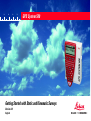
Getting Started with Static and Kinematic Surveys
Version 2.0
English
System GPS500
Congratulations on your purchase of a new Leica
System GPS500.
2
Static and Kinematic Surveys-2.0.0en
View of chapters
Introduction
6
Equipment checklist for static and rapid static measurements using system 500
7
Setting up System 500 for a static survey
8
Using the TR500 terminal
9
Taking Static / Rapid-Static measurements
13
Exploring the sensor status during operation
23
Changing the system configuration parameters
29
Creating new configuration sets
33
Programming wake-up sessions
34
Kinematic and Stop & Go surveying - using static initialization
37
Kinematic "on the fly"
43
Practical hints for kinematic, Stop & Go and
45
Miscellaneous
46
Appendix: Summary of status icons
47
Appendix: Measuring antenna heigths
49
Static and Kinematic Surveys-2.0.0en
3
View of chapters
Contents
Introduction ................................................... 6
Exploring the sensor status during operation
...................................................................... 23
Equipment checklist for Static and RapidStatic measurements using System 500 ..... 7
Satellite status ............................................................24
Stop & Go indicator .....................................................25
Battery and memory status .........................................26
Display current navigated position ................................27
Suggested exercise: Get familiar with system status ....28
Setting up System 500 for a static survey ... 8
Using the TR500 terminal ............................. 9
Changing the system configuration
parameters ................................................... 29
Menus ......................................................................... 9
Entering information ....................................................10
Listboxes .................................................................... 11
Hardkeys ....................................................................12
Turning on the illumination of the terminal .....................30
Changing the observation rate ......................................30
Setting local time zone ................................................31
Changing distance units from meter to feet ...................32
Taking Static / Rapid-Static measurements 13
Step 1: Power on ........................................................13
Step 2: Study the icons ...............................................13
Step 3 (optional): Format your memory card .................15
Step 4: Begin a survey ................................................16
Step 5: Logging raw data .............................................19
Step 6: Ending a survey ..............................................21
Suggested exercise: Measure a very short baseline .....22
Contents
Creating new configuration sets ................ 33
Programming Wake-up Sessions .............. 34
4
Static and Kinematic Surveys-2.0.0en
Contents, contd.
Kinematic and Stop & Go surveying - using
static initialization ........................................ 37
Introduction and general comments .............................37
Equipment setup for Kinematic and Stop & Go surveys 38
Carrying out Kinematic and Stop & Go measurements .39
Initialization on a known point ......................................42
Kinematic "on the fly" ................................. 43
Practical hints for Kinematic, Stop & Go and
Kinematic on the fly measurements .......... 45
Miscellaneous .............................................. 46
Appendix: Summary of status icons ......... 47
Appendix: Measuring antenna heights ..... 49
Static and Kinematic Surveys-2.0.0en
5
Contents
6
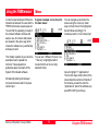
Introduction
The purpose of this short manual is
to give guidelines and useful hints on
how to perform static, rapid static and
kinematic surveys using SR510,
SR520 or SR530 GPS receivers
without utilizing Realtime techniques.
Realtime applications, based on the
use of radio modems - in particular
RTK (Real-Time-Kinematic) operation with SR530 receivers - are
described in the booklet "Getting
Started with Real-Time Surveys".
Full description of all features and
functions of System 500 can be
found in the "Technical Reference"
Manual which is available as an
electronic PDF document only. This
manual can be found on the SKI-Pro
installation CD. For more information
please refer to the file
\MANUALS\README.TXT on the
SKI-Pro installation CD.
Introduction
It is assumed that the reader of this
manual is familiar with the principles
of GPS Surveying, i.e. he knows the
concept of differential measurements, the need for a reference
receiver, etc. A basic introduction of
these principles is given in the
booklet "General Guide to Static and
Rapid Static".
After studying these guidelines a user
will know the basic concepts and
principles of how to operate System
500 and carry out static, rapid static
and kinematic GPS surveys.
6
Static and Kinematic Surveys-2.0.0en
Equipment checklist for Static and Rapid-Static measurements using System 500
If you want to use System 500 for
Static or Rapid-Static survey then the
minimum equipment you need is a
pair of System 500 units.
Each unit comprises a SR510 or
SR520 or SR530 sensor.
A single frequency SR510 sensor
requires an AT501 single frequency
antenna; SR520 and SR530 sensors
need to be connected to a dualfrequency antenna, normally the
AT502 standard antenna or - for
utmost accuracy - high precision
chokering antennas: either a AT503
or AT504.
An antenna cable is needed to
connect the sensor and the antenna.
A TR500 terminal - a keyboard &
display device - is needed to easily
start the operation, check system
status and manipulate sensor
parameters.
Static and Kinematic Surveys-2.0.0en
6
Batteries are needed to power the
sensor. Standard are two camcorder
batteries which are plugged into the
backside of the sensor and power the
unit for about 6 hours.
7
Warning
Brand new camcorder
batteries need about 5
charging cycles before
reaching the full capacity. It is
highly recommended to fully
charge and decharge
camcorder batteries for 4 to 5
times before start-ing using
them for practical fieldwork.
This is easily accomplished
by plugging them into the
sensor and having the sensor
turned on until the sensor
switches off automatically
once the batteries get flat.
Then simply recharge them
and repeat this exercise.
7
Equipment checklist
Setting up System 500 for a static survey
6 Successful GPS surveys require
7
8
undisturbed satellite signal reception.
This means that GPS sensors should
be set up in locations which are free
of obstructions. No obstacles like
trees, buildings, mountains, etc.
should block the line between the
GPS antenna and GPS satellites.
This holds true in particular for the
sensor which serves as the
reference.
For static and rapid static surveys,
the antenna must be kept perfectly
steady throughout the whole
occupation of a point. This means
that the AT501 or AT502 antenna will
usually be put on a tripod.
Connect the antenna to the sensor
using the antenna cable.
Plug two camcorder batteries into the
backside of the sensor. Alternatively
or in addition you might want to
power the sensor externally. In this
case connect a GEB71 battery to one
of the PWR- ports of the sensor.
Use the hook on the backside of the
sensor to hang it on one of the tri-pod
legs. Alternatively you may want to
leave the sensor inside the shipping
case.
Your System 500 sensor is now fully
ready for operation.
Attach the TR500 terminal to the
sensor, either directly or via a
connection cable by plugging it into
the TERMINAL-port on the sensor.
Insert a PC-card into the sensor.
Center and level the tripod precisely
above the survey marker. Place and
lock the carrier in the tribrach. Mount
the antenna onto the carrier.
Setting up System 500 for a Static survey
Warning
Lock the lid carefully after
insertion of the card in order
to prevent water and dust
from getting inside the
sensor.
8
Static and Kinematic Surveys-2.0.0en
Using the TR500 terminal
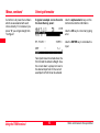
Menus
In order to operate System 500 some
interactions between the user and the
TR500 terminal are usually required.
You will find the operating concept of
the onboard software intuitive and
easy to use. All screens and panels
are steered in the same way which
makes the software very userfriendly
and easy to learn.
A typical example can be found in
the main menu:
This chapter explains by use of some
examples how to operate the
terminal. These operational
guidelines apply to all parts of the
System 500 onboard software.
You can see 7 different choices. Line
"1 Survey" is highlighted which
means that this is the currently
selected choice.
6
7
8
9
We basically distinguish between
menus and screens which require a
certain input.
Static and Kinematic Surveys-2.0.0en
You can navigate up and down the
screen using the cursor up / down
keys on the terminal. The highlighted
bar will follow accordingly. For
instance press the "cursor down key"
9
twice to highlight "3 Applications":
The function keys at the bottom of the
screen describe certain commands. If
for instance you want to enter the
"Applications" part of the software you
press F1 CONT (to continue).
Using the TR500 terminal
6
7
8
Menus, continued
Entering information
A shortcut is to press the numbers
which are associated with each
choice directly. For instance if you
press "6" you will get straight into
"Configure"
A typical example can be found in
the main Survey panel:
Use the alphanumeric keys on the
terminal to enter the information.
Use the CE key to correct any typing
error.
9
Use the ENTER key to conclude the
input.
Two inputs have to be made here, the
Point Id and the Antenna Height. Use
the cursor down / up keys to move to
the desired input field. In the current
example the Point Id can be entered.
Using the TR500 terminal
10
Static and Kinematic Surveys-2.0.0en
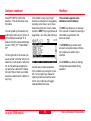
Entering information, contd.
Listboxes
When ENTER is pressed the focus is
moved to the next input field:
Some input fields expect a predefined
input. The choices are available in a
list which is kept behind the input
field.
Input fields based on a listbox are
identified by a small triangle which
appear on the right side of the field.
The following example shows 3 such
input fields in one screen:
The input for Configuration Set, Job
and Antenna has to be made based
on a list.
Press ENTER to open the highlighted
listbox. A list pops up from which a
choice has to be made:
Use numeric keys to enter the
antenna height.
Use the cursor down / up keys to
move the selection bar down or up the
list. Select your input by highlighting
the particular line.
Static and Kinematic Surveys-2.0.0en
11
Using the TR500 terminal
6
7
8
9
6
7
8
9
Listboxes, continued
Press F1 CONT to confirm the
selection. This will then also close
the listbox
You can speed up the selection by
entering the name of your choice. If
in this particular example "T" is
entered, the focus will automatically
move to "TEST_PP Rapid Static
PP".
On the right side of the screen you
see a vertical "scroll bar" which indicates the current positio n within the
list. In this particular example the
current focus is about 20 % below
the top of the list. Such a scrollbar
becomes useful when the listbox is
very long.
Using the TR500 terminal
Hardkeys
If the listbox is very long it might
become cumbersome to navigate by
pressing cursor down / up to move
down and up the list. In such cases
press the SHIFT key to get access to
page down / up, home and end keys:
The terminal supports some
additional useful hardkeys:
The ESC key allows you to "escape"
from a screen. Instead of executing a
command you get back to the
previous screen.
The STATUS key provides direct
access to all system status information, based on a certain menu
structure
Another way to make a selection
from a listbox is by using the cursor
left / cursor right keys. Instead of
opening a list box press the cursor
left or cursor right keys to toggle
between different choices.
12
The CONFIG key allows to change
configuration parameters during
operation.
Static and Kinematic Surveys-2.0.0en
Taking Static / Rapid-Static measurements
6
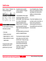
Step 2: Study the icons
Turn on the sensor by pressing the
ON-button on the terminal. One of
the following two screens will appear
on the display:
Most important at this stage is the top
part of the screen which contains
several symbols (icons) which
indicate the current system status.
Accu
racy
Statu
s
Posit
ion M
ode
No. v
isible
Sate
llites
No. S
atellit
es us
ed on
L1/L2
Radio
Statu
s
GSM
Statu
s
Mem
ory S
Auto
tatus
Posit
ion L
og. S
tatus
Obse
rvatio
n Log
. Statu
s
Loca
l Tim
e
Batte
ry Sta
tus
Step 1: Power on
Upon power on you will first recognize
the "Number of visible Satellites"
icon, indicating the number of
satellites which are theoretically
visible at the current location and
time. Usually this number varies
between 4 and 10, depending on the
satellite geometry.
Static and Kinematic Surveys-2.0.0en
13
Next to this symbol you find the
"Number of Satellites used on L1 /
L2" icon, indicating the number of
satellites currently tracked either on
L1 or on L2.
Upon power on you will read L1: 0,
L2: 0. It will take about 30 seconds
until these number will start changing
and very soon reach the number of
visible satellites.
Both "Number of visible satellites"
and "Number of satellites used" icons
will change from time to time, reflecting changes in the satellite
geometry due to either the rise of
new satellites or the setting of descending satellites.
Taking Static / Rapid-Static measurements
7
8
9
13
6
7
8
9
3
Step 2: Study the icons, continued
Once a minimum of 3 satellites is
tracked the sensor can start
computing a position. As soon as a
position is available it will be
indicated by an icon on the far left of
the status line. Since for postprocessing surveys no realtime link
will be used, the icon will always
indicate the availability of an
autonomous position ("navigated
position") with an accuracy of about
100 meters.
As soon as the position icon
becomes visible the sensor is in a
stage where practical operation can
commence.
If the position icon does not become
visible even after one or two minutes
then the sensor is still not tracking
satellites. If the "number of satellites
used" is still zero please check
whether the antenna cable is
connected properly to both sensor
and antenna.
If the "number of satellites used"
differs from the "number of visible
satellites" make sure you place the
antenna in an open area without
obstructions, since any obstacle will
block the view of satellites.
When you switch on the unit for the
very first time it might take a maximum of 5 minutes until all satellites
are tracked. This can happen in case
your current location differs
significantly (i.e. > 1000 km) from the
initial position which is the position
where your sensor has been used
before. Once you are tracking
satellites, the position memory in the
sensor will be updated.
The battery status icon at the right
side of the icon line shows from
which source the sensor is currently
powered. A and B indicate the
internal batteries, E an external
battery source. The symbol also
indicates the voltage level of the
currently used battery in 4 different
stages from "full" (fully black) to 2/3
to 1/3 and "almost flat" (white color).
Taking Static / Rapid-Static measurements
14
The memory status icon gives
several information: whether memory
for logging data is available or not.
Options are either a PC-card or
internal memory. If a PC card is
available and configured for use then
at this stage an arrow indicates the
fact that it is safe to remove the PCcard from the sensor. The little bar on
the right side indicates the available
memory on either the PC-card or the
internal memory.
Warning
You cannot proceed from
here if no memory device is
avail-able. Insert a PC-card
other-wise no GPS survey
can be carried out.
All status symbols which are relevant
for static and kinematic measurements are listed in the appendix.
Static and Kinematic Surveys-2.0.0en
Step 3 (optional): Format your memory card
Before you start logging data you
may want to (re-)format your PC-card
or your internal memory.
You are now in the Utilities \ Format
Memory Module panel:
This step is only necessary if
a completely new PC-card is
used or all existing data
should be deleted !
If you want to format the PC-card just
press F1 CONT to format the card. If
you want to format the internal
memory press ENTER. A listbox
opens which allows you to select the
internal memory.
7
8
9
13
Press 4 on the terminal or use the
cursor down key to highlight the line
"4 Utilities", then press ENTER;
alternatively press F1 CONT.
(If only lines 1 to 3 are visible at this
stage press F4 SHOW first).
Then press 2 to get access to the
"Format Memory Module" panel, or
alternatively use the cursor key to
navigate to "2 Format Memory Module" and press ENTER; again
alternatively press F1 CONT.
Static and Kinematic Surveys-2.0.0en
6
15
Taking Static / Rapid-Static measurements
6
7
8
9
3
Step 3 (optional): Format your memory card, continued
Step 4: Begin a survey
Use the cursor key to highlight
Internal, then press ENTER. Then
press F1 CONT in order to start the
formatting process of the internal
memory.
Enter the Survey operation by either
pressing 1 in the Main\ panel or by
first navigating to "1 Survey" via
cursor keys and then pressing
ENTER or F1 CONT.
Once the formatting of the card is
completed the MAIN\ panel will
reappear.
Warning
By activating the format
command all data will be lost!
Make sure that all important
data which resides on the
PC-card is properly backedup before reformatting the
card. If you want to reformat
the internal memory make
sure that all important data is
first transferred to the PC.
The following panel will appear:
Some basic decisions have to be
made in this panel:
Which configuration set should be
activated, in which job the raw data
should be stored and which antenna
setup should be used.
If you realize that you do not want to
format the memory device, simply
press ESC instead of F1 CONT. This
keystroke brings you always a step
back into the previous panel without
execution of any command.
Taking Static / Rapid-Static measurements
16
Static and Kinematic Surveys-2.0.0en
Step 4: Begin a survey, continued
A Configuration Set (Config Set) is a
collection of certain sensor
parameters needed to perform a
certain operation, like data recording
rates, point id templates, data
formats, antenna types, coding
methods, etc.
Several default configuration sets
exist which cover standard survey
scenarios. How to create new
configuration sets is described in a
later chapter as well as in the
Technical Reference Manual.
For static survey you should select
the PP_STAT configuration set. You
can make this selection either by
using the cursor left key to toggle
between all available configuration
sets until PP_STAT appears or you
can highlight the input field and press
ENTER.
Static and Kinematic Surveys-2.0.0en
Then a list box showing all available
sets becomes available:
Now use the cursor up or cursor
down key on the terminal to highlight
the PP_STAT line. Then press
ENTER or F1 CONT.
Upon formatting the memory device
(i.e. PC-card or internal memory) a
default job is automatically created.
You can either use this job straight
away or you can create your own job
by doing the following:
Move the cursor up or cursor down
key of the terminal into the input field
for jobs. Then press ENTER. The
following lisbox will appear:
Jobs are used to organize and
structure the data you collect in the
field. Jobs can comprise an unlimited
number of points together with all
related information (raw measurements, codes, point annotation, etc.).
It is suggested to create a new job
whenever you start a new project.
17
Taking Static / Rapid-Static measurements
6
7
8
9
13
6
7
Step 4: Begin a survey, continued
Now press F2 NEW. The following
panel appears:
As an example we can create a new
job called "Test":
You can now enter a name for a new
job; press ENTER upon completing
the input of the name. Input fields for
description and creator are optional
and can be left blank.
By default the new job will be
assigned to the PC-card. If needed
this can be changed to internal by
toggling this input field to "Internal".
After pressing F1 CONT the list of
available jobs is updated and now
also shows the job "Test":
8
9
3
Pressing F1 CONT which confirms
the creation of a new job name and
its location. Press ESC if you want to
leave this field without creating a new
job. Pressing F6 QUIT has the same
effect.
Taking Static / Rapid-Static measurements
18
Now press F1 CONT to confirm the
selection of the newly created job.
Finally you have to select the
antenna type and antenna setup
which you are using. Normally this
will be AT502 on tripod (or AT501 on
tripod in case of a SR510 sensor).
See Technical Reference Manual
"Measuring Antenna Heights" for
further details.
Static and Kinematic Surveys-2.0.0en
Step 4: Begin a survey, contd.
Step 5: Logging raw data
This selection is made in the usual
way: first use the cursor down key to
get this input field highlighted. Then
use the cursor left key to toggle
among the several options until the
right one appears. Alternatively you
can press the ENTER key to get a
listbox from which the choice can be
made.
We are now within the main Survey
panel. The way the sensor is
currently configured, the panel will
look as follows:
Now all required settings for a static
survey are made. The Survey \ Begin
panel looks as follows:
Pressing F1 CONT finishes this
startup sequence.
Static and Kinematic Surveys-2.0.0en
As soon as you are tracking a
minimum of 4 satellites, the position
icon is visible and the antenna is
placed correctly above the survey
marker, you should press F1 OCUPY.
This activates logging of raw data
and the screen changes accordingly:
It is time to check again the icons on
the top of the display: The position
icon should be available, the position
mode icon still indicates "moving" ,
the "number of satellites visible" icon
should display a number greater or at
least 4, and the number of used
satellites should be identical to the
number of visible satellites.
19
The position mode icon has changed
to static, indicated by a symbol of a
tripod.
Taking Static / Rapid-Static measurements
6
7
8
9
13
6
7
8
9
3
Step 5: Logging raw data, continued
A new icon is now displayed which
indicates that raw data is logged.
Raw data (containing pseudorange
and phase measurements to each
tracked satellite) is logged at
predefined intervals (by default every
10 seconds, which is the
"observation recording rate" set in the
default PP_STAT configuration set):
Enter a Point Id by filling in the input
field. If you make a typing error
correct the mistake by pressing the
CE key (Clear Entry). Complete the
input by pressing ENTER.
Now use the height hook to
determine the height of the antenna
above the survey marker. Insert the
height hook into the carrier and
measure the height between the
white mark at the bottom of the
height hook and the survey marker.
Enter this reading into the antenna
height field. Since the antenna you
have selected is "AT502 Tripod"
(AT501 Tripod in case of a SR510
sensor) the offset from the height
hook to the phase center of the
anten-na is automatically taken care
of.
These are the only two inputs needed
for surveying a point.
The Static observation counter
(Static obs) will now go up every 10
sec-onds (because this is the default
logging interval).
The displayed GDOP value indicates
the current satellite geometry; the
lower the value the better.
Taking Static / Rapid-Static measurements
Warning
The antenna must not be
moved while data is logged,
other-wise the quality of postprocessed coordinates will be
impaired !
20
Warning
The PC-card must not be
removed while in the Survey
panel. If the card is taken out
of the sensor all stored data
might get corrupted,
preventing SKI-Pro from
successfully reading the data
on the card.
The TR500 terminal may now be
disconnected. This will have no effect
on the survey ! Datalogging will
continue. When reconnecting the terminal the same panel will reappear.
Datalogging should continue
depending on your observation plan:
a sensor used as reference has to
run permanently until all rover site
occupa-tions are completed. If a unit
is operated as a roving receiver the
site occupation time depends mainly
on the baseline length and your
accuracy requirements. See "General
Guide to Static and Rapid Static" for
details.
Static and Kinematic Surveys-2.0.0en
Step 5: Logging raw data, continued
Step 6: Ending a survey
Once sufficient amount of raw data
has been collected the survey of the
point can be completed by pressing
F1 STOP.
The STORE key has become active,
and you have still the chance to
check and correct entered point id
and antenna height.
You can now quit the survey operation
panel by pressing SHIFT F6 QUIT.
This brings you back to the main
menu.
6
The screen is altered as follows:
Conclude the survey sequence by
again pressing F1 STORE.
Pressing SHIFT F6 will
always allow you to terminate
the survey operation, even
during a site occupation. In
this case you will loose all
data collected since pressing
OCUPY.
9
After pressing the STORE key all
related information will be stored in
the currently used job (point id,
antenna heights, etc.)
As soon as you are back to the main
menu the PC-card may be removed.
This is indicated by the PC-card icon
in the status line which contains an
arrow:
Static and Kinematic Surveys-2.0.0en
21
Taking Static / Rapid-Static measurements
7
8
13
6
7
8
9
3
Step 6: Ending a survey, conts.
Suggested exercise: Measure a very short baseline
You can now switch off the sensor.
Once power is off, put the equipment
back into the shipping case.
It might be a useful exercise to start
with a very simple static baseline.
You might now move to another site
and repeat the procedure outlined in
this chapter. Once your fieldwork is
finished you can proceed by
processing the collected data in SKIPro in order to get accurate baseline
results.
Choose a location which is free of
obstructions.
Mark two points on the ground
which are a few meters apart and
measure the distance by tape (for
comparison later on)
Transfer the data of both sensors
into SKI-Pro and post-process the
collected raw data.
Compare the GPS results with your
initial tape reading. The resulting
slope distance should not differ by
more than a few millimeters.
Set up two System 500 sensors on
tripod as explained in chapter 2.
Log raw data simultaneously on
each unit for about 10 minutes,
using the PP_STAT configuration
and newly created jobs.
Measure and record the height of
the antennas correctly using the
height hook.
Enter Point Id's of your choice
Taking Static / Rapid-Static measurements
22
Static and Kinematic Surveys-2.0.0en
Exploring the sensor status during operation
The terminal gives direct access to
all relevant status information via a
dedicated STATUS key. This key located in the center of the terminal is accessible at any time and
regardless of the current system
operation. By pressing STATUS the
following menu appears:
It is now very simple to navigate
further through all available status
screens. Either use the cursor up /
cursor down key to highlight the
various options, then press either F1
CONT or ENTER. A quicker way is to
press numbers 1 , 2, 3 or 4 to get
direct access to the next level of
status menus.
A detailed description of all status
screens can be found in the
Technical Reference Manual.
This short guideline will only
concentrate on the screens which are
important for Static and Rapid-Static
measurements.
Static and Kinematic Surveys-2.0.0en
23
Exploring the sensor status during operation
6
7
8
9
13
23
6
7
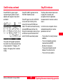
Satellite status
Select "1 Survey" \ "5 Satellite". The
following display appears:
8
9
3
3
For each satellite the following
information is provided:
SV number
Elevation and azimuth
Signal strength on L1 and L2
Quality indicator for L1 and L2
measurements
This panel provides valuable
information on the current
performance of your sensor:
All satellites above the default
minimum elevation of 15 degree
should be tracked.
Tracked satellites will show signal
strength values between 32 and 51
(SN1 and SN2 - Signal / Noise values
on L1 and L2). High elevation
satellites should have values
between 45 and 51. Low elevation
satel-lites (elevations below 20
degree) will show values between 32
and 40.
Not tracked satellites are shown with
a dash line instead S/N values.
If you find satellites above 15 degree
which are not tracked then the line of
sight between the antenna and the
satellite is most likely blocked by
obstructions.
If more than 6 satellites are in view
you have to use the cursor down / up
keys to scroll up and down the
screen and get the information on
those satellites which do not fit onto
the same screen.
The measurement quality is indicated
with numbers of up to 99 in the QI1
and QI2 column. Values will usually
vary between 80 and 99. Lower
values indicate disturbed signal
reception, for instance caused by
trees, leaves, or very active
atmospheric conditions.
Exploring the sensor status during operation
24
Static and Kinematic Surveys-2.0.0en
Satellite status, continued
Press F5 SKY to get a skyplot
representing the position of each
satellite with respect to the Zenith
and North:
Stop & Go indicator
Press F1 CONT to get back to the
STATUS \ Satellite screen.
Press F1 again to exit the STATUS
menu and return directly to the
screen from where STATUS was
called. The same can be achieved by
pressing ESC several times; this
brings you back step by step until you
will also end up at the screen from
which STATUS was initially called.
The center of the graph represents
the Zenith, the circles represent lines
of equal elevation: 15 degree - 30
degree - 60 degree (from outside to
inside).
Static and Kinematic Surveys-2.0.0en
25
The Stop & Go indicator helps users
to judge the necessary site
occupation time for rapid static
measurements for sensors used as
rovers.
A minimum site occupation time is
calculated depending on various
parameters such as:
- The number of currently tracked
satellites
- The current satellite geometry
(represented as GDOP)
- Number of cycle slips
- The assumed baseline length
between the reference site.
- The current rover position.
Exploring the sensor status during operation
6
7
8
9
13
23
6
7
8
Stop & Go indicator, contd.
Once a point is occupied a percentage counter becomes active
which informs the user on the site
occupation status:
9
3
3
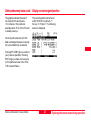
Battery and memory status
The way the completion counter is
programmed is based on years of
practical experience. Although the
settings are on the conservative side
there is no guarantee that baseline
results will meet the accuracy
specifications of System 500 after the
post-processing of the data.
This quite useful screen is found
under "3 General" \ "1 Memory /
Battery".
Press F1 CONT to return to the
previous operation.
The numbers given represent the still
available amount of capacity.
It is recommended to continue data
logging until the completion counter
indicates at least 100 %.
For instance in this particular
example there is still 1.1 MB memory
left on the PC-card.
Additional information provided in this
panel is the time already spent on the
point, the estimated time to go (until
100% completion is achieved),
number of cycle slips which occurred
since the start of this site occupation,
current GDOP as well as the number
of recorded static observations.
Exploring the sensor status during operation
26
Static and Kinematic Surveys-2.0.0en
Battery and memory status, contd. Display current navigated position
The graphics indicate the level of
consumption for each device.
For instance in this particular
example about 35 % of the PC-card
is already used up.
The current position can be found
under STATUS in submenu "1
Survey / 3 Position". The following
screen is displayed:
7
8
9
Currently active devices (for both
data recording and power consumption) are indicated by an asterisk
13
23
Pressing F1 CONT gets you back to
your previous operation. Pressing
ESC brings you back one level only
(in this particular case to the "STATUS \ General" Menu.
Static and Kinematic Surveys-2.0.0en
6
27
Exploring the sensor status during operation
6
7
8
9
3
3
Suggested exercise: Get familiar with system status
Start up a sensor and begin a
Survey.
Start measuring a point (by
pressing F1 OCUPY in the main
Survey panel)
Explore various status screens:
- Satellite Status
- Skyplot
- Watch the Stop & Go indicator
- Check battery level
- Current (navigated) position
Finish the site occupation (by
pressing STOP and STORE after
entering a Point Id and an Antenna
Height).
Exploring the sensor status during operation
28
Static and Kinematic Surveys-2.0.0en
Changing the system configuration
parameters
The
user has direct access to all
It is again very easy to navigate
configuration parameters via the
CONFIG key.
Almost all currently used
configuration parameters can be
altered any time. Access to these
parameters is via the CONFIG
button. Upon pressing it, the following
menu appears:
6
further and get access to individual
parameters: Either by pressing
numbers (e.g. 2 for Operation) or by
using the cursor down / up keys and
to highlight the line of interest and
then pressing F1 CONT.
7
8
9
13
A detailed description of all configuration parameters can be found in
the Technical Reference Manual.
This guideline will focus on those
which are of importance to Static and
Rapid-Static measurements only.
23
29
33
In the five following subchapters we
describe 5 different configuration
examples which are of relevance for
static and kinematic surveys.
Static and Kinematic Surveys-2.0.0en
29
Changing the system configuration
6
7
Turning on the illumination of the terminal
Changing the observation rate
Certain parameters of the Terminal
can be configured under "3 General\
6 TR500" :
You might want to change the rate at
which observations are recorded.
This parameter can be found under
"2 Operation \ 3 Logging":
8
The requested changes are activated
upon pressing F1 CONT. This keystroke brings you then straight back
to the screen from which the
Configuration program was activated.
9
3
3
9
3
In the same panel you can also
activate or deactivate an audible
alarm and keyclick.
Illumination and contrast of the
display of the terminal can be turned
on or off. Use the "Cursor left" key to
toggle between yes and no. If you
select yes you should specify a timeout: once this set time is expired, the
illumination is switched off again.
Changing the system configuration
Move the focus to the next line by
pressing the cursor down key. Then
either press ENTER to get access to
a list box with all possible rates (from
0.1 sec to 60 sec) or use the cursor
left / right keys to toggle among these
options one by one.
30
Static and Kinematic Surveys-2.0.0en
Changing the observation rate, contd.
Warning
If "Log Static Obs" is
switched to NO then no raw
data will be logged anymore.
No data will then be available
for post-processing !
Setting local time zone
It is not recommended to
switch "Log Moving Obs" to
YES ! This parameter is only
of interest in case kinematic
observations should be postprocessed.
6
7
8
9
13
If you change the recording
rate please keep in mind that
only those observations can
be post-processed for which
data for both reference and
rover sensors is available. If
for instance one unit is recording every 10 seconds,
and the other unit is recording
every 15 seconds then only
data every 30 seconds is
common and can be postprocessed !
Static and Kinematic Surveys-2.0.0en
The local time zone can easily be set
under "3 General \ 4 Time & Initial
position":
23
Move the highlighted bar down to
"Time Zone" by using the cursor
down key. Then either toggle with the
cursor left / right keys until the right
zone appears or press ENTER to
open the listbox with all possible
options.
31
Changing the system configuration
29
33
6
7
8
9
3
3
9
3
Setting local time zone, contd.
Changing distance units from meter to feet
Afterwards press F1 CONT to
activate the selection. You will then
see the correct local time being
displayed in the upper right corner of
the status line.
This can be done in panel CONFIG "3
General / "1 Units". The following
screen becomes accessible:
There is usually no need to modify
initial time or the initial position, even
if the current settings are completely
wrong. The sensor will automatically
enter a "search the sky" mode and as
soon as satellites are tracked time
and position will be updated
automatically.
Changing the system configuration
To change units for distances move
the focus to this input field. Then use
either ENTER to get access to a
listbox from which the preferred
choice can be made; or alternatively
use the cursor left / right keys to
toggle to the units of your choice
(meters, US feet, etc.).
Also other unit parameters can be
changed here, for instance the format
in which dates should be displayed.
Confirm changes by pressing F1
CONT. If you want to exit this panel
without making any changes simply
press ESC to get one level back.
32
Static and Kinematic Surveys-2.0.0en
Creating new configuration sets
In case the factory default
configuration sets do not fully meet
your requirements you can easily
create new ones by carrying out the
following procedure:
Highlight the configuration set which
you want to copy to a new one. The
parameters of this set will be copied
across to the new one you will create
by pressing F2 NEW.
Select "6 Configure" from the Main
menu. The main menu is the first one
to appear after power on. In case
only menu items 1 to 3 are visible
press F3 SHOW first.
The following display appears:
A new configuration set under the
name "Test_PP" has been created.
The parameters are equivalent to the
one of "PP_STAT".
7
8
9
13
23
29
The following display appears:
Type in a new name. Input of a
description and a creator's name is
optional. Finish this step by pressing
F1 CONT.
Now we are ready to edit the
parameters of this new configuration
set. Just press F3 EDIT to get into a
sequence of several screens which
contain all relevant configuration
parameters.
If you press ESC instead, then you
return to the previous screen without
having created a new configuration
set.
Static and Kinematic Surveys-2.0.0en
6
33
Changing
thenew
system
configuration
Creating
configuration
sets
33
6
7
8
9
3
3
9
3
4
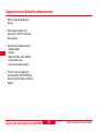
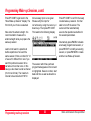
Programming Wake-up Sessions
The Auto-Wake-up functionality
allows you to preprogram the
operation of a sensor. By defining
start and end times and a
configuration set the sensor will
automatically start up at the
predefined time and take
measurements according to the
configured parameters and again
stop at the predefined time.
This function is useful if a sensor has
to be left unattended and the GPS
survey campaign is still hours ahead.
This way battery power and memory
is saved.
Navigate to the Wake-up session
menu. This menu can be found under
"3 Applications / 04 Wake-up
Sessions":
The following display appears:
Press F1 CONT.
The following display appears:
Wake-up sessions are programmed
in the following way:
Programming wake-up sessions
In this screen it is now possible to
create new sessions, edit and delete
existing sessions:
Press F2 NEW to create a new
Wake-up Session.
34
Define the job in which the data
should be stored. Highlight this input
line and press ENTER. This gives
you the opportunity to select from the
list of existing jobs or to create a new
job.
Static and Kinematic Surveys-2.0.0en
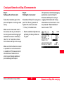
Programming Wake-up Sessions, contd.
Define the configuration set you want
to use. Highlight this input field and
press ENTER. A listbox will appear
from which you can choose the
appropriate configuration set. Make
sure that this set is configured such
that observations will be logged otherwise there will be no data
available for subsequent
postprocessing in SKI-Pro.
Define Start Date by typing in the
date when the session should be
executed.
Then press the cursor down key to
get access to additional input fields:
6
7
8
9
13
23
You have to enter a Point Id.
Navigate to this input field and press
ENTER in order to get access to the
point management:
Define Start Time by typing in the
time the session should start.
Define the duration of the session.
The format is hours: minutes:
seconds (hh:mm:ss).
Static and Kinematic Surveys-2.0.0en
If the point list is empty or the point
you want to occupy is not contained
in the list you have to create a new
point by pressing F2 NEW:
35
29
Enter a Point Id. You can leave the
coordinates blank (the correct input
of these coordinates is only of
importance for points which should
be used as realtime reference sites):
Press F1 STORE to create the new
point and get back to the previous
display.
Programming wake-up sessions
33
34
6
7
8
9
3
3
9
3
4
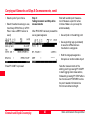
Programming Wake-up Sessions, contd.
Press F1 CONT to get back to the
"New Wake-up Session" display. The
Point Id of your choice is selected.
Now enter the antenna height. It is
recommended to measure the
antenna height while you prepare the
wake-up session.
Last but not least it is possible to
define repetitions of one and the
same session. Enter a number for " #
of execut's" different from one if you
want this particular session to be
carried out more than once. In this
case you also have to enter a interval
(hh:mm:ss format). The maximum
interval to be entered is 23:59:59
Programming wake-up sessions
All necessary input is now given.
Please verify the input for
correctness by using the cursor up /
down keys. Then press F1 CONT.
This leads to the following display:
Press F1 CONT to confirm the newly
created wake-up session. It is then
safe to turn off the sensor. The
sensor will then automatically
execute the operation as defined in
the session parameters.
Alternatively press F4 DEL to delete
an already programmed session, or
press F3 EDIT to modify an existing
session, or press F2 NEW to create
another new Wake-up Session.
The session which has just been
programmed appears on the list and
is highlighted. Session number, start
date and time as well as duration is
displayed.
36
Static and Kinematic Surveys-2.0.0en
Kinematic and Stop & Go surveying - using static initialization
6
Introduction and general
comments
Kinematic measurements will provide
the trajectory of a moving antenna. If
for instance raw data is logged every
second, the result will be 3 dimensional coordinates for every second the
antenna was moved.
While kinematic measurements are
only time related but not point
related, Stop & Go measurements
deliver coordinates for discrete points
which are occupied for a short period
of time, usually a few seconds.
In order to achieve position
accuracy's on the centimeter level in
a moving environment the so called
"ambiguities" must be resolved. The
safest way is to start Kinematic and
Stop & Go surveys with a static
initialization. Usually about 5 minutes
of dualfrequency static observations
Static and Kinematic Surveys-2.0.0en
7
on a baseline not longer than 3 - 5
km will be sufficient to resolve ambiguities in post-processing. Once this
static initialization is accomplished
the GPS antenna can be moved and
other points of interest can be
occupied with only a few seconds of
measurements. High accuracy's will
be maintained as long as satellite
signal reception is not interrupted, for
instance by obstructions.
As soon as a complete loss of signal
lock occurs - this means that the
signal of satellites is interrupted such
that less than 4 satellites remain
unaffected - the high accuracy of
results is lost and ambiguities must
be reestablished first. This means
that in such a case another static
initialization is required.
37
Kinematic and Stop & Go surveying
is an efficient way of measuring many
points quickly and efficiently, provided
the following criteria are met:
Distances between the reference
receiver and the rover is fairly
short, ideally less than 3 km.
Baselines above 5 km should be
avoided if possible.
The surveying area is fairly open
with not many obstructions
between points. Obstructions will
cause satellite signal interruptions
which can cause complete losses
of lock. In such cases static reinitializations become necessary
which slow down the field
operation.
Kinematic and Stop & Go surveying
8
9
13
23
29
33
34
37
6
7
8
9
3
3
9
3
4
7
Equipment setup for Kinematic and Stop & Go surveys
The rover is kept perfectly steady
during the static initialization.
Movements of even a few
centimeters only can cause
difficulties in post-processing of
such data, leading to unresolved
ambiguities and therefore poor
accuracy of the starting point as
well as all subsequently measured
points.
On the reference site static
measurements have to be taken.
Follow the instructions given in
chapters 1 to 4 with regard to
conducting static survey operations.
A static re-initialization is always
carried out after a complete loss of
lock.
The GPS antenna can be mounted
on a rangepole, and the sensor can
be stored in the System 500 Minipac;
alternatively the whole sensor can be
kept on the rangepole itself.
Satellite geometry is strong. This
means that a minimum of 5
satellites should be visible
throughout the whole operation,
preferably 6 or more satellites.
Kinematic and Stop & Go surveying
The roving sensor however might be
configured differently in order to allow
efficient operation while moving from
point to point.
38
The System 500 rangepole is
designed such that either the
terminal or the sensor itself can be
attached easily. The length of the
rangepole is such that the total
instrument height of an AT501 or
AT502 antenna equals exactly 2
meters. All vertical antenna offsets
are taken care of.
See the Technical Reference Manual
for details on how to setup a System
500 sensor for kinematic and stop &
go surveys.
Static and Kinematic Surveys-2.0.0en
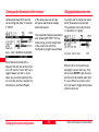
Carrying out Kinematic and Stop & Go measurements
Step 1:
Setting up the reference site
Step 2:
Starting the rover sensor
Follow the instructions given in the
previous chapters on running a static
survey.
Kinematic and Stop & Go surveys are
part of the "Survey" operation of
System 500, to be found under
"1 Survey" in the Main menu.
Make sure the "observation rate" is
the same as the one you choose for
the roving sensor and that logging of
static data is turned on. Normally a
rate of 2, 3 or 5 seconds is chosen
for Kinematic and Stop & Go surveys.
Of importance is that the data logging
parameters are set correctly for
Kinematic and Stop & Go surveys.
Logging for both static and moving
observations must be turned on. Also
the parameter "Static Initialization"
has to be set to "YES" :
Select a suitable configuration set,
preferably the factory default set
"PP_KIS".
7
8
9
13
23
29
33
Make sure that the reference receiver
is operated in an environment which
is suitable for GPS measurements; it
should be free of obstructions in
order to avoid missing satellites or
poor satellite signal reception.
Static and Kinematic Surveys-2.0.0en
6
34
37
39
Kinematic and Stop & Go surveying
Carrying out Kinematic and Stop & Go measurements, contd.
6
Select a job of your choice.
7
Select the antenna setup you use,
most likely AT502 Pole (or AT501
Pole in case a SR510 sensor is
used):
8
9
Step 3:
Taking kinematic and Stop & Go
measurements
After F1 CONT has been pressed the
survey panel appears:
Use a tripod on the starting point
Use supporting legs (quickstand)
in case the GPS antenna is
mounted on a rangepole
3
3
9
Hold the rangepole against a
fencepole or another stable object
3
4
Start with a static point measurement. Measure a point for a few
minutes. Make sure you keep the
antenna steady:
Take the measurements of the
starting point by pressing F1 OCUPY
to start logging static observations,
followed by pressing F1 STOP after a
few minutes and F1 STORE to store
the point related information like
Point Id and Antenna Height.
Press F1 CONT to proceed.
7
Kinematic and Stop & Go surveying
40
Static and Kinematic Surveys-2.0.0en
Carrying out Kinematic and Stop & Go measurements, contd.
You are now ready to move your
antenna. You can expect coordinates
with centimeter accuracy as long as
lock to a minimum of 4 to 5 satellites
is maintained.
Observations are logged while
moving, which is indicated by a
switch in the status symbol from
"Static" to "Moving":
If you are only interested in the
trajectory of your antenna, then just
get moving. Postprocessing will
provide you with time tagged
coordinates for every epoch at which
observations are logged (normally
every 2, 3 or 5 seconds).
Static and Kinematic Surveys-2.0.0en
If you want to pick up subsequent
discrete points then just move to the
next point you want to measure.
Then press F1 OCUPY, and hold
your antenna steady for a few
seconds. You have to remain on the
point until at least one epoch of
"Static observations" has been
recorded. You can then again press
F1 STOP and F1 STORE to
complete the point measurement. A
Point Id and antenna height must be
entered for such Stop & Go points.
Post-processing will provide results
with point id's and associated
coordinates.
41
Make sure you avoid obstructions
when you move from point to point.
Severe obstructions might cause a
complete loss of lock which in turn
will cause a loss of accuracy in postprocessing. A static reinitialization will
become mandatory in such a case. A
warning message will be displayed to
inform the user to start another
"chain" of measurements:
6
7
8
9
13
23
"Another static initialization is
necessary"
29
In this case logging of raw data stops
automatically. Thus you now must
carry out another static initialization
(see above).
34
Kinematic and Stop & Go surveying
33
37
6
Initialization on a known point
Step 4:
Ending a kinematic and stop & go
operation.
Static initializations can be speeded
up by occupying a point with known
coordinates.
End a kinematic or stop & go survey
by pressing SHIFT F6 QUIT. This will
of course also end logging of raw
data.
3
If the coordinates of a point are
known in the WGS84 system to
within 5 - 10 cm, the static
initialization can be accomplished
with about 20 to 30 seconds of
measurements (10 to 15 epochs).
9
Get into the main Survey panel
7
8
9
3
3
Start measuring by pressing F1
OCUPY in order to log
observations on that point. Keep
the rangepole steady !
4
7
After about 20 to 30 seconds press
F1 STOP.
Make sure you enter the correct
point id and antenna height. Then
press F1 STORE.
Kinematic and Stop & Go surveying
42
You can now start moving and
occupy subsequent points with few
seconds of measurements. The
need for another static initialization
arises only in case of a complete
loss of lock, although it is
recommended to keep such a
"track" of measurements short
(e.g. maximum of 20 points).
When you post-process the data in
SKI-Pro you have to mark such
tracks as "Init (track)"; this ensures
that SKI-Pro relies on the already
existing coordinates for this point to
fix ambiguities. Again, it is important
that the coordinates of the starting
points are accurate to within 5 to 10
cm within the WGS84 system.
This method of initialization is of
particular interest for SR510 sensors
because static initializations on
unknown points are very time
consuming with single-frequency
receivers.
Static and Kinematic Surveys-2.0.0en
Kinematic "on the fly"
Kinematic on the fly measurements
provide the trajectory of a moving
sensor without the necessity of a
static initialization. The sensor can be
moved from the first observation
epoch onwards.
Accurate results on the centimeter
level can only be obtained if dualfrequency phase measurements are
available. Thus this method is
restricted to SR520 and SR530
sensors. Single-frequency receivers
like the SR510 sensor cannot be
used for precise kinematic on the fly
measurements.
The disadvantage of this method is
that an absolute minimum of 5
satellites on L1 and L2 is needed to
allow a fixing of ambiguities "on the
fly" in post-processing.
Discrete points can also be
measured within a "kinematic on the
fly" measurement chain.
It is important that the logging
parameters are set correctly. The
parameter "Static Init" must be set to
"NO", while logging of static observations and moving observations
must be set to "YES".
Thus the operation procedure is very
similar to standard Kinematic and
Stop & Go surveying as described in
the previous chapter.
6
7
8
9
13
23
29
33
34
37
The advantage of this measurement
method is that the sometimes timeconsuming static initialization is
avoided, thus the productivity in the
field will be higher.
Static and Kinematic Surveys-2.0.0en
Configuration parameters for
kinematic on fly:
Make sure that the recording rate at
the rover sensor is the same as on
the reference site.
43
Kinematic "on the fly"
43
45
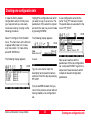
Kinematic "on the fly", contd.
6
Taking measurements
7
As soon as the main Survey panel is
accessed, data logging commences
according to the configured logging
parameters. You will see the status
icons changing from moving to static
in case you press F1 OCUPY. After
finishing a point occupation by
pressing F1 STOP and F1 STORE
the measurement mode will switch
back to "moving".
8
9
3
3
9
3
4
7
3
5
SKI-Pro will process such data and
resolve ambiguities "on the fly". It is
recommended to collect about 2
minutes of cycle slip free data before
you start occupying points. Otherwise
you take the risk that ambiguities
cannot be resolved and the accuracy
of such points will certainly not meet
the specification of 1 - 2 cm + 1 ppm.
Kinematic "on the fly"
The Stop & Go indicator will provide
useful information for this kind of
operation (while you are moving):
"5 Sat's since mm:ss" tells the
operator the time elapsed since
tracking started or since the last
complete loss of lock. It is
recommended to start occupying
points only once this counter exceeds
2 minutes. In case of a complete loss
of lock (i.e. the number of satellites
tracked on both L1 and L2 falls below
5, the counter is reset to zero.
44
Post-processing of Kinematic-onthe-fly measurements
SKI-Pro will treat the data as so
called "Mixed Tracks". Both static
and moving data is contained in one
and the same chain of measurements:
In the example above points 1 to 5 are
static points. Data-processing will
compute and provide a position for
each static point by averaging the
results of each epoch of data which
was taken during the static occupation.
Static and Kinematic Surveys-2.0.0en
Practical hints for Kinematic, Stop & Go and Kinematic on the fly measurements
It is very important to use a period
of time where the satellite
constellation is strong; a window
with more than 6 satellites is ideal.
Distances between reference and
rover should be kept short. Ideally
this distance does not exceed 3 to
5 km
6
Include independent checks in your
measurements. Either measure a
point twice based on different
initializations, or include known
points into your survey.
7
8
9
13
23
It is recommended to keep a
"track" (consisting of the
observations taken during static
initialization as well as during
moving and occupying
subsequently measured Stop & Go
points) short. It is suggested to
end a track after e.g. a maximum
of 20 points and then reinitialize
again. You can force the system to
do so by just blocking the GPS
antenna by hand for some
seconds until the message
"Complete loss of lock" appears.
Static and Kinematic Surveys-2.0.0en
29
33
34
37
43
45
45
Kinematic
Practical
"on thehints
fly"
6
7
8
9
3
3
9
3
4
7
3
5
6
7
9
Miscellaneous
These guidelines cover only a small
subset of the functionality which is
available on System 500 sensors.
Most of the functionality is used only
in realtime applications.
This chapter lists additional features
which might be of use also for static
or kinematic surveys. Detailed
descriptions can be found in the
Hardware User Manual.
System 500 sensors can be used
without any terminal at all. Sensors
can be preprogrammed in a way
that only the "On"-button has to be
pressed, then everything else is
done automatically, even the
switch-off of the sensor.
System 500 sensors are equipped
with 3 LED's which provide status
information on power, tracking,
and memory. The LED's are visible
when the terminal is not attached
to the sensor.
Miscellaneous
System 500 supports two levels of
operation modes. Standard and
advanced. Certain parameters are
de-activated in standard mode for
simplicity reasons and therefore
can only be accessed if the sensor
is previously configured to
"Advanced" mode.
System 500 supports a comprehensive coding system. By default
coding is deactivated for simplicity
reasons. Point related thematical
coding is possible as well as free
sequential coding.
System 500 is equipped with a
calculator function. This can be
found under "3 Applications \ 03
Calculator".
The System 500 sensor firmware
supports a multilanguage concept.
English is the master language
and permanently loaded. Several
local language versions exist
which can be loaded and activated
in parallel. Talk to your local Leica
dealer for details.
In Status all measured points of a
job can be viewed.
It is possible to automatically
increment point id's, based on
user- definable templates.
46
Static and Kinematic Surveys-2.0.0en
Appendix: Summary of status icons
The following Status Icons are
supported by the sensor during static
and kinematic measurements.
6
Number of visible satellites
7
8
Position / accuracy status
Navigation (<100m)
When no icon is shown no position is
available. This usually means that no
(or not enough satellites) are tracked.
Other accuracy levels are not
supported unless realtime corrections
are received through a radio.
Position mode
The number of theoretically visible number of satellites according to the
currently used almanac is displayed.
Number of satellites used on L1 and L2
9
13
23
29
33
The number of currently tracked satellites are shown.
If a SR510 single frequency sensor is used only the L1 line is active.
34
37
43
Static - the GPS Antenna
should be held stationary.
45
Moving - The GPS Antenna
may move.
47
Static and Kinematic Surveys-2.0.0en
46
49
47
Appendix: Summary of status icons
6
7
Appendix: Summary of status icons, contd.
Memory status
Battery status
Internal Memory selected
Battery Voltage OK
PC-Card selected
Battery supplying 2/3 peak voltage
Safe to remove PC-Card
Battery supplying 1/3 peak voltage
3
Memory level Indicator. Has 12 levels between:
Battery empty
9
Memory Empty and
8
9
3
3
4
Memory Full
7
3
5
6
7
9
Observation recording status
The Receiver is recording raw GPS
observations in Stationary mode. The Receiver
should be held stationary.
The battery being used is denoted by a letter next to it. A
and B are the plugin camcorder batteries, E indicates a
connected external 12 V battery.
Local time
Local time can be displayed in either an 12 hour format
or an 24 hour format. The time appears in the upper right
corner of the status line.
The Receiver is recording raw GPS observations in Moving mode. The Receiver may move.
Appendix: Summary of status icons
48
Static and Kinematic Surveys-2.0.0en
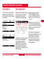
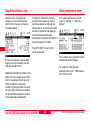
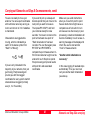
Appendix: Measuring antenna heights
MRP
VE1 VE2
MRP
MRP
VE1 VE2
6
VE1 VE2
VO=0
VO = 0
VO
VR
7
8
9
VR
13
VR
23
29
33
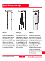
AT502 Pole
AT502 Tripod
AT502 Pillar
If you are using the antenna on a
pole select the antenna type AT502
Pole (or AT501 Pole) during the
begin of a survey. The Vertical Height
Reading (VR) per default is 2m.
Normally you do not have to change
this value. The Vertical Offset (VO) is
0m and is applied automatically.
If you are using the antenna on a
tripod together with the height hook
select the antenna type AT502 Tripod
(or AT501 Tripod) during the begin of
a survey. Measure and enter the
Vertical Height Reading (VR). The
Vertical Offset (VO) is 0.360m and is
applied automatically.
If you are using the antenna on a
pillar or a tripod without height hook
select the antenna type AT502 Pillar
(or AT501 Pillar) during the begin of a
survey. Measure and enter the
Vertical Height Reading (VR) from
the pillar benchmark to the
Mechanical Reference Plane (MRP).
The MRP is the underside of the
threaded metal insert at the bottom of
the antenna housing.
Static and Kinematic Surveys-2.0.0en
49
Appendix: Measuring antenna heights
34
37
43
45
46
47
49
Leica Geosystems AG, Heerbrugg,
Switzerland, has been certified as being
equipped with a quality system which
meets the International Standards of
Quality Management and Quality
Systems (ISO standard 9001) and Environmental Management Systems (ISO
standard 14001).
712172en-2.0.0
Printed in Switzerland - Copyright Leica Geosystems AG,
Heerbrugg, Switzerland IV.1999
Original text
Total Quality ManagementOur commitment to total customer
satisfaction
Ask your local Leica agent for more
information about our TQM program
Leica Geosystems AG
Geodesy
CH-9435 Heerbrugg
(Switzerland)
Phone +41 71 727 31 31
Fax +41 71 727 46 73
www.leica-geosystems.com