1
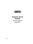
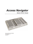
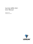
4.0 INSTALLATION
The Model 2090 is equipped with a DTE, network, and power
interface. This section briefly describes connection to each.
4.1 DTE INTERFACE CONNECTION
The DTE interface is a V.35 DCE presented as an M/34 male connector. This interface is designed to plug directly into a DTE interface
(See Appendix D for V.35 interface pin assignments).
5.0 OPERATION
Once the Model 2090 is installed and configured properly it is
ready to place into operation. This section describes the function of
the LED indicators, the use of the loopback test modes and the control
port.
5.1 LED DESCRIPTIONS
The Model 2090 Series is equipped with seven LED indicators that
monitor the status of communication. Figure 3 (below) shows the location of the LEDs on the Model 2090 Series front panel.
4.2 NETWORK INTERFACE CONNECTION
The Network Line Interface is an eight position keyed modular jack
configured as a RJ-48C. This interface will need to be configured to
match the line parameters (i.e. framing, line coding) supplied by the
connected equipment.
NOTE: If the Model 2090 Series is being used for private short
range modem applications, the twisted pair cable connected to its
port will need to be a cross-over cable. See Appendix D for
Interface pin assignments.
TXD
LOS
ALM
4.3 POWER CONNECTION
ERR
T/L
Model
2711
Model 2090
RXD
PWR
The Model 2090 Series is powered via a supplied external transformer and is factory configured for either 120VAC or 100-240VAC
operation. This connection is via the barrel jack on the rear of the
2090. The Model 2090 can also be powered via the DTE interface
when supplied with +5VDC @ 300mA to Pin KK. See Appendix D for
more information.
Figure 3. Top of Model 2090, Showing LED Indicators
15
TXD
(Transmit Data) glows green to indicate data flow to
Model 2090 from the DTE.
RXD
(Receive Data) glows green to indicate data flow from the
Model 2090 to DTE.
LOS
(Loss of Sync) glows red to indicate a network Loss of
Frame or Loss of Signal condition.
16