1
NOVA-3710/3710SV
CeleronTM , Pentium® III Processor
Multimedia , Dual VGA & Ethernet
Embedded Board
©Copyright 2003 by ICP Electronics Inc. All Rights Reserved.
Manual Ver 2.1 edition Feb.1, 2003.
The information in this document is subject to change without prior notice in
order to improve reliability, design and function and does not represent a
commitment on the part of the manufacturer.
In no event will the manufacturer be liable for direct, indirect, special,
incidental, or consequential damages arising out of the use or inability to
use the product or documentation, even if advised of the possibility of such
damages.
This document contains proprietary information protected by copyright. All
rights are reserved. No part of this manual may be reproduced by any
mechanical, electronic, or other means in any form without prior written
permission of the manufacturer.
Trademarks
NOVA-3710/3710SV is a registered trademark of ICP Electronics Inc. IBM
PC is a registered trademark of International Business Machines
Corporation. Intel is a registered trademark of Intel Corporation. AWARD is
a registered trademark of Award Software Internation, Inc. Other product
names mentioned herein are used for identification purposes only and may
be trademarks and/or registered trademarks of their respective companies.
Contents
1. Introduction........................................................ 4
1.1
Specifications ...................................................................................5
1.2
What You Have ................................................................................7
2. Installation ......................................................... 8
2.1
NOVA-3710/3710SV Layout .............................................................9
2.2
Unpacking Precautions………………………………………………..10
2.3
Clear CMOS Setup.........................................................................11
2.4
COM 2 RS-232 / 422 / 485 Setup ..................................................11
2.5
COM PORT RI and Voltage Selection............................................12
2.6
LCD Panel power Setup.................................................................13
2.7
LCD Panel Clock Setup..................................................................14
2.8
LCD Panel Type Selection .............................................................14
2.9
CompactFlash™ Disk Setting.........................................................14
2.10
Keyboard Use Selection.................................................................15
2.11
C&T 69000 H/W Enable Disable ...................................................15
3. Connection ...................................................... 16
3.1
Floppy Disk Drive Connector..........................................................16
3.2
PCI E-IDE Disk Drive Connector ....................................................17
3.3
Serial Ports.....................................................................................18
3.4
Serial Port ( For COM2 RS422/485 ) .............................................19
3.5
Keyboard Connector ......................................................................19
3.6
External Switches and Indicators....................................................19
NOVA-3710/3710SV Socket 370 CeleronTM & Pentium III ®
Multimedia & Dual VGA , Ethernet Embedded Board
1
3.7
USB Port Connector.......................................................................20
3.8
IrDA Infrared Interface Port ............................................................20
3.9
VGA Connector...............................................................................21
3.10
LAN RJ45 Connector .....................................................................22
3.11
Fan Connector................................................................................22
3.12
Temperature Sensor Connector.....................................................23
3.13
Audio CD IN Connector ..................................................................23
3.14
Audio MIC IN Connector .................................................................23
3.15
Compact Flash Connector.............................................................23
3.16
Power Connector............................................................................24
3.17
LCD Back-light Connector.............................................................25
3.18
Digital Input / Output Connector .....................................................25
3.19
LCD Panel Connector ...................................................................26
3.20
I/O Connector .................................................................................27
4. AWARD BIOS Setup ....................................... 29
4.1
Introduction.....................................................................................29
4.2
Starting Setup.................................................................................29
4.3
Using Setup....................................................................................30
4.4
Getting Help ...................................................................................31
4.5
Main Menu......................................................................................32
4.6
Standard CMOS Setup...................................................................35
4.7
Advanced BIOS Features Setup.....................................................39
4.8
Advanced Chipset Features Setup.................................................44
NOVA-3710/3710SV Socket 370 CeleronTM & Pentium III ®
Multimedia & Dual VGA , Ethernet Embedded Board
2
4.9
Integrated Peripherals Setup..........................................................51
4.10
Power Management Setup ............................................................55
4.11
PnP/PCI Configuration Setup .........................................................59
4.12
PC Health Status Setup…………….. .............................................61
4.13
Frequency / Voltage Control Setup …………….. ...........................63
4.14
Defaults Menu Setup ……………...................................................64
4.15
Change Supervisor/User Password…………….. ...........................65
4.16
Exit Selection ……………...............................................................66
Appendix A. WatchDog Timer........................................67
Appendix B. POST Messages ........................................69
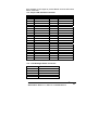
Appendix C.
DMA , IRQ , 1st MB Memory and I/O Address Map...75
Appendix D. How to Upgrade a New BIOS ...................77
Appendix E. Digital Input / Output Address .................80
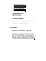
Appendix F. Flat Panel Connection Module …………….
81
NOVA-3710/3710SV Socket 370 CeleronTM & Pentium III ®
Multimedia & Dual VGA , Ethernet Embedded Board
3
1
Introduction
Welcome to the NOVA-3710/3710SV Socket 370 Celeron®,
Pentium III® (FC-PGA) with 10/100Mbps Ethernet , Dual VGA ,
Audio Board. It is equipped with high performance Intel® Celeron
up to 677MHz( or above ) , Pentium III ( FC-PGA ) 500-933MHz
( or above ) Processor and advanced high performance multimode I/O, designed for the system manufacturers, integrators, or
VARs that want to provide all the performance, reliability, and
quality at a reasonable price.
This board has a built-in IDE Interface CompactFlash™ Disk
( Type II ) for embedded application. The CompactFlash™ Disk
is 100% compatible to hard disk. User can use DOS command
without any extra software utility. The Flash Disk currently is
available from 8MB to 1GB.
Two advanced high performance LPC super I/O chip – ITE
( IT8705F ) and NS ( NS87366 ) are used in the NOVA3710/3710SV board. The on-chip UART is compatible with the
NS16C550. The parallel port and FDD interface are compatible
with IBM PC/AT architecture.
NOVA-3710/3710SV uses the advanced SIS SIS630S Chipset
which is 100% PCI compatible with PCI 2.1 standard. In addition,
this board provides one 168-pin sockets for its on-board DRAM.
NOVA-3710/3710SV Socket 370 CeleronTM & Pentium III ®
Multimedia & Dual VGA , Ethernet Embedded Board
4
The DIMM module uses 3.3V SDRAM and support maximum
512MB for each module.
Two VGA chip ( C&T 69000 & On chip SIS300) are used on
NOVA-3710/3710SV that supports dual view function which can
display simultaneously on two monitors when you enter
WINDOWS 9X/ME/2000.
1.1 Specifications :
•
CPU : support Intel Celeron® up to 677 MHz ( or above ) , Pentium III
( FC-PGA ) 500-933 MHz (or Above ) Processor. Supports 66MHz,
100MHz and 133 MHz FSB.
•
Expansion Bus : PCI bus, expansion to support PCI bus signal
•
DMA channels : 7
•
Interrupt levels : 15
•
Chipset : SIS630S 66/100/133MHz CPU / DRAM Clock
•
DRAM : One 168-pin DIMM socket ,supports SDRAM RAM module,
up to 512MB.
•
AGP VGA Controller : On chip SIS300 3D ( Share memory up
to 64MB RAM)
AGP bus speed : 66MHz
VESA Compatible Resolution Graphic Mode up to
1600 x 1200 256/32K colors
1280 x 1024 256/32K/64K/16M colors
1024 x 768 256/32K/64K/16M colors
800 x 600 16/256/32K/64K/16M colors
640 x 480 16/256/32K/64K/16M colors
•
PCI VGA Controller : On Onboard C&T69000 ( 2MB memory )
NOVA-3710/3710SV Socket 370 CeleronTM & Pentium III ®
Multimedia & Dual VGA , Ethernet Embedded Board
5
PCI bus speed : 33MHz
VESA Compatible Resolution Graphic Mode up to
1024 x 768 256/64K colors
800 x 600 16/256/64K/16M colors
640 x 480 16/256/64K/16M colors
•
Support 3.3V( SIS300) ,3.3V ( C&T69000 ) Flat Panel.
•
Support 24bit TFT wide range flat panel.
•
Optional ( LVDS-01 ) One Channels LVDS module.
•
10/100Mbps Ethernet Controller : Realtek 8100, Auto-sensing
interface to 10Mbps, 100Mbps Network , RJ45 connector for 10BASETX and 100BASE-TX , Full Duplex capability , Full Software driver
support
•
Ultra DMA/66 (Enhanced PCI IDE Interface) : Supports two PCI
Enhance IDE hard drives. The Ultra DMA/66 IDE can handle data
transfer up to 66MB/s. The best of all is that this new technology is
compatible with existing ATA-2 IDE specifications. So, there is no
need to do any change for customer’s current accessory.
•
Multi-I/O Chip : IT8705F,NS87366, all I/O setup by BIOS
Three 16C550 RS-232C Ports One RS-232 or RS-422/485 Port
One EPP/ECP Parallel Port, Floppy Port. The
RS485 features auto-direction control. No extra direction control is
needed.
•
Floppy disk drive interface : Two 2.88 MB, 1.44MB, 1.2MB, 720KB,
or 360KB floppy disk drives.
•
Four high speed Serial ports : NS16C550 compatible UARTs
•
Bi-directional Parallel Port : One parallel port support, IEEE 1284
compatible .
•
IrDA port : Support Infrared and Amplitude Shift Keyed IR(ASKIR)
interface.
NOVA-3710/3710SV Socket 370 CeleronTM & Pentium III ®
Multimedia & Dual VGA , Ethernet Embedded Board
6
•
USB port : Support Two USB ports for future expansion. USB V1.2
compatible .
•
Watchdog timer : Can be set to 1 minute ( Minimal )or above period.
Reset is generated when CPU does not periodically trigger the timer.
Your program uses hex 440 to control the watch-dog and generate a
system reset.
•
CompactFlash Disk – Type II CompactFlash™ Disk . The Flash Disk
provides 100% compatibility with IDE hard disk.
•
Digital I/O : 4 Digital Input and 4 Digital Output channels
•
SIS7018 PCI Audio Chipset: Sound Blaster compatible and Roland
MPU401 compatible ( AC97 )
•
Support ATX Power function
•
Dual View Function
•
Mouse & Keyboard Connector : PS/2 Mouse Port Expansion
Keyboard.
•
Power Consumption : +5V : 7.5A (Pentium III 933MHz, 256MB
SDRAM ) +12V : 0.5A
•
Operating Humidity : 5 ~ 95 % , non-condensing
•
Operating Temperature : 0° ~ 55° C ( CPU needs Cooler)
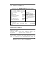
1.2 What You Have
In addition to this User's Manual, the NOVA-3710/3710SV
package includes the following items:
®
• NOVA-3710/3710SV Socket 370 Celeron , Pentium III &
Ethernet , Dual VGA , Audio Board
If any of these items is missing or damaged, contact the dealer
from whom you purchased the product. Save the shipping materials
and carton in case you need to ship or store the product in the
future.
NOVA-3710/3710SV Socket 370 CeleronTM & Pentium III ®
Multimedia & Dual VGA , Ethernet Embedded Board
7
2
Installation
This chapter describes how to install the NOVA-3710/3710SV.
The layout of NOVA-3710/3710SV is shown on the next page and
the Unpacking Precautions that you should be aware of are
described on the following page. Also included are the jumpers
and switches setting for this board’s configuration, such as: CPU
type selection, system clock setting and Watchdog timer.
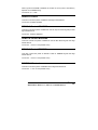
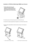
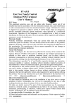
2.1 NOVA-3710/3710SV 's Layout
< please, refer to the next page >
NOVA-3710/3710SV Socket 370 CeleronTM & Pentium III ®
Multimedia & Dual VGA , Ethernet Embedded Board
8
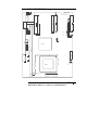
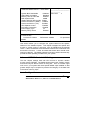
2.1
NOVA-3710/3710SV 's Layout
CN4
CN2
CN1
CN5
JP2
CN3
CN13
1
2
C N17
CN 16
JP3
CN8
CN14
CN15
CN7
J P1
1
CN6
1
CN9
JP7
2
JP4
JP5
CN 10
JP8
JP6
JP9
CN 11
CN12
JP10
CN19
1
SIS630S
DIMM
CN20
SL1
JP11
CN23
CN21
CN22
10
11
1
JP13
CPU
CN24
CN26
CN25
NOVA-3710/3710SV Socket 370 CeleronTM & Pentium III ®
Multimedia & Dual VGA , Ethernet Embedded Board
9
2.2 Unpacking Precautions
Some components on NOVA-3710/3710SV are very sensitive to
electrical static discharges and may cause damage to the board. To
prevent such unintended damage, be sure to follow these precautions:
9
Discharge yourself from electrical static prior to handling the NOVA3710/3710SV. You can do it by using a grounded wrist strap at all
time or by frequently touching any conducting materials that is
connected to the ground.
9
Handle your NOVA-3710/3710SV by its edges. Try not to have any
physical contact with the components on the NOVA-3710/3710SV.
9
Do not plug any connector or jumper while the power is on.
9
Do not put your NOVA-3710/3710SV unprotected on a flat surface
because it has components on both sides.
NOVA-3710/3710SV Socket 370 CeleronTM & Pentium III ®
Multimedia & Dual VGA , Ethernet Embedded Board
10
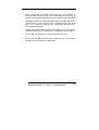
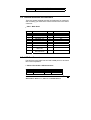
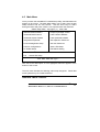
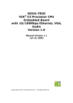
2.3 Clear CMOS Setup
If you forget the CMOS password, you can clear or reset it by
closing the JP11. After JP11(1-2) is closed, turn on the power
for about 3 seconds then turn it off and open the JP11(1-2).
Now, the password has been cleared from your CMOS.
• JP11 : Clear CMOS Setup
1
2
3
z
z
z
PIN NO.
2-3
1-2
2.4
DESCRIPTION
Normal Operation
Clear CMOS Setup
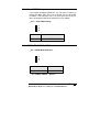
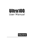
COM2 RS-232/422,485 Selection
• JP1 : COM2 Mode Selection
z
z
z
3
2
1
JP1
1-2
2-3
DESCRIPTION
RS232
RS422/RS485
** 2-3 RS422 / RS485 ( Option )
NOVA-3710/3710SV Socket 370 CeleronTM & Pentium III ®
Multimedia & Dual VGA , Ethernet Embedded Board
11
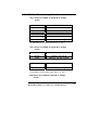
2.5
COM Port RI and Voltage Selection
• JP3: Set pin 9 of COM1 as signal RI or voltage
source
JP3
DESCRIPTION
9-11
7-9
COM1 RI Pin Use RI
COM1 RI Pin Use Voltage
JP3
DESCRIPTION
1-3
3-5
COM1 RI Pin Use Voltage +5V
COM1 RI Pin Use Voltage +12V
* If JP3 Uses ( 9-11 ) Don’t care JP3 (1-3 , 3-5 )
• JP3: Set pin 9 of COM2 as signal RI or voltage
source
JP3
DESCRIPTION
10-12
8-10
COM2 RI Pin Use RI
COM2 RI Pin Use Voltage
JP3
DESCRIPTION
2-4
4-6
COM2 RI Pin Use Voltage +5V
COM2 RI Pin Use Voltage +12V
* If JP3 Uses ( 10-12 ) Don’t care JP3 ( 2-4 , 4-6 )
•JP4:Set pin 9 of COM3 as signal RI or voltage
source
NOVA-3710/3710SV Socket 370 CeleronTM & Pentium III ®
Multimedia & Dual VGA , Ethernet Embedded Board
12
JP4
DESCRIPTION
10-12
8-10
COM3 RI Pin Use RI
COM3RI Pin Use Voltage
JP4
2-4
4-6
DESCRIPTION
COM3 RI Pin Use Voltage +5V
COM3RI Pin Use Voltage +12V
* If JP4 Uses ( 10-12 ) Don’t care JP4 ( 2-4 , 4-6 )
• JP4: Set pin 9 of COM4 as signal RI or voltage
source
JP4
DESCRIPTION
9-11
7-9
COM4 RI Pin Use RI
COM4RI Pin Use Voltage
JP4
DESCRIPTION
1-3
3-5
COM4 RI Pin Use Voltage +5V
COM4RI Pin Use Voltage +12V
* If JP4 Uses ( 9-11 ) Don’t care JP3 ( 1-3 , 3-5 )
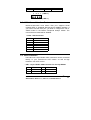
2.6 LCD Panel power Setup
To set the operating voltage for the LCD Panel.
• JP6 : On Chip SIS 300 LCD Power Setting
z
z
z
1
2
3
NOVA-3710/3710SV Socket 370 CeleronTM & Pentium III ®
Multimedia & Dual VGA , Ethernet Embedded Board
13
JP6
DESCRIPTION
2-3
+3.3V
1-2
+5V
* Set to +5V is NOT standard
• JP5 : On Board C&T69000 LCD Power Setting
JP5
4-6
2-4
DESCRIPTION
+3.3V
+5V
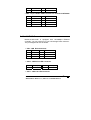
2.7 LCD Panel Clock Setup
To set the C&T 69000 LCD clock type for the LCD Panel.
• JP5 : On Board C&T 69000 LCD Power Setting
JP5
3-5
1-3
DESCRIPTION
Normal
Invert
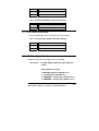
2.8 LCD Panel Type Selection
NOVA-3710/3710SV can support up to 24 bit LCD.
• JP7,8,9,10 : On Chip SIS300 LCD Panel Type Selection
( H/W )
Now support LCD Type:
1.
2.
3.
4.
IMES M121-SOHR ( 800x600 TFT)
LG LM151X2 ( 1024x768 TFT )
SAMSUNG LT121S1-153 ( 800x600 TFT )
SAMSUNG LT121S1-106 ( 800x600 TFT )
NOVA-3710/3710SV Socket 370 CeleronTM & Pentium III ®
Multimedia & Dual VGA , Ethernet Embedded Board
14
z z z
1 2 3
JP7
2-3
2-3
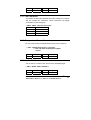
2.9
JP8
2-3
2-3
JP9
1-2
2-3
JP10
2-3
2-3
DESCRIPTION
1024X768 TFT
800X600 TFT
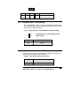
CompactFlash™ Disk Setting
The CompactFlash™ Disk is 100% compatible to IDE hard disk.
The CompactFlash™ Disk is available from 8MB to 1GB. It also
accepts type II IBM MicroDrive .
• JP2: CompactFlash™ Disk IDE Master & Slave Setting
z
z
1
2
* CompactFlash™ Disk Use Secondary
IDE Channel
PIN NO.
DESCRIPTION
Open
Short
Slave
Master
2.10 Keyboard Use Selection
The NOVA-3710/3710SV provides CN20 keyboard connector or
option keyboard output for IO connector.
• CN20 : 6-pin Header Mouse Connector
CN20
2-3 , 4-5
OPEN
DESCRIPTION
KB use for IO connector
KB use for CN20
NOVA-3710/3710SV Socket 370 CeleronTM & Pentium III ®
Multimedia & Dual VGA , Ethernet Embedded Board
15
2.11 C&T69000 H/W Disable Selection
The NOVA-3710/3710SV provides JP13 select C&T69000
Chipset Enable , Disable.
• CJP13 : Select C&T 69000 H/W Enable , Disable
JP13
CLOSE
OPEN
DESCRIPTION
Enable C&T 69000
Disable C&T 69000
3
Connection
This chapter describes how to connect peripherals, switches and
indicators to the NOVA-3710/3710SV board.
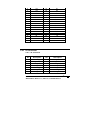
3.1 Floppy Disk Drive Connector
NOVA-3710/3710SV board is equipped with a 34-pin daisy-chain
driver connector cable.
• CN8 : FDD CONNECTOR
PIN NO.
DESCRIPTION
PIN NO.
DESCRIPTION
NOVA-3710/3710SV Socket 370 CeleronTM & Pentium III ®
Multimedia & Dual VGA , Ethernet Embedded Board
16
1
3
5
7
9
11
13
15
17
19
21
23
25
27
29
31
33
GROUND
GROUND
GROUND
GROUND
GROUND
GROUND
GROUND
GROUND
GROUND
GROUND
GROUND
GROUND
GROUND
GROUND
GROUND
GROUND
GROUND
2
4
6
8
10
12
14
16
18
20
22
24
26
28
30
32
34
REDUCE WRITE
N/C
N/C
INDEX#
MOTOR ENABLE A#
DRIVE SELECT B#
DRIVE SELECT A#
MOTOR ENABLE B#
D4IRECTION#
STEP#
WRITE DATA#
WRITE GATE#
TRACK 0#
WRITE PROTECT#
READ DATA#
SIDE 1 SELECT#
DISK CHANGE#
NOVA-3710/3710SV Socket 370 CeleronTM & Pentium III ®
Multimedia & Dual VGA , Ethernet Embedded Board
17
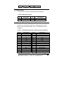
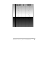
3.2 PCI E-IDE Disk Drive Connector
You can attach two IDE (Integrated Device Electronics) hard disk
drives to the NOVA-3710/3710SV IDE controller. The maximum
data transfer rate is 66M B/s . In this case , the cable total length
shall not exceed 0.46 m ( 18in ).
CN3 ( 44Pin 2.0mm IDE 2 ) : Secondary IDE Connector
CN15 ( 40Pin 2.54mm IDE 1) : Primary IDE Connector
• CN3 : IDE2 Interface Connector
PIN NO.
DESCRIPTION
PIN NO.
1
3
5
7
9
11
13
15
17
19
21
23
25
27
29
31
33
35
37
39
41
43
RESET#
DATA 7
DATA 6
DATA 5
DATA 4
DATA 3
DATA 2
DATA 1
DATA 0
GND
IDE DRQ
IOW#
IOR#
IDE CHRDY
IDE DACK
INTERRUPT
SA 1
SA 0
HDC CS0#
HDD ACTIVE#
+5V
GND
2
4
6
8
10
12
14
16
18
20
22
24
26
28
30
32
34
36
38
40
42
44
DESCRIPTION
GND
DATA 8
DATA 9
DATA 10
DATA 11
DATA 12
DATA 13
DATA 14
DATA 15
N/C
GND
GND
GND
GND
GND
N/C
N/C
SA 2
HDC CS1#
GND
+5V
+5V
NOVA-3710/3710SV Socket 370 CeleronTM & Pentium III ®
Multimedia & Dual VGA , Ethernet Embedded Board
18
• CN15 : IDE1 Interface Connector
PIN NO.
DESCRIPTION
PIN NO.
1
3
5
7
9
11
13
15
17
19
21
23
25
27
29
31
33
35
37
39
RESET#
DATA 7
DATA 6
DATA 5
DATA 4
DATA 3
DATA 2
DATA 1
DATA 0
GND
IDE DRQ
IOW#
IOR#
IDE CHRDY
IDE DACK
INTERRUPT
SA 1
SA 0
HDC CS0#
HDD ACTIVE#
2
4
6
8
10
12
14
16
18
20
22
24
26
28
30
32
34
36
38
40
DESCRIPTION
GND
DATA 8
DATA 9
DATA 10
DATA 11
DATA 12
DATA 13
DATA 14
DATA 15
N/C
GND
GND
GND
GND
GND
N/C
N/C
SA 2
HDC CS1#
GND
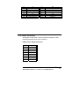
3.3 Serial Ports
The NOVA-3710/3710SV offers four high speed NS16C550
compatible UART with Read/Receive 16 byte FIFO serial ports
(COM3/COM4).
NOVA-3710/3710SV Socket 370 CeleronTM & Pentium III ®
Multimedia & Dual VGA , Ethernet Embedded Board
19
• CN22 , CN23 : Serial Port 2x5 pin header Connector
(COM4,3)
Pin No.
1
3
5
7
9
Description
Pin No. Description
DCD
RXD
TXD
DTR
GND
2
4
6
8
10
DSR
RTS
CTX
RI
NC
3.4 Serial Ports ( For COM2 RS422/485 )
The NOVA-3710/3710SV offers RS422 / 485 option for COM2 .
• CN1 : 4-pin Header for S422 / RS485 Mode
RS422 / 485 Mode
PIN NO.
DESCRIPTION
1
2
3
4
3.5
TX+
TXRX+
RX-
Keyboard Connector
The NOVA-3710/3710SV provides one internal keyboard
connectors.
• CN20 : 6-pin Header Mouse Connector
PIN NO.
DESCRIPTION
1
2
3
4
VCC
KB-CLK / To IO connector
KB-CLK / From chipset
KB-DATA / To IO connector
NOVA-3710/3710SV Socket 370 CeleronTM & Pentium III ®
Multimedia & Dual VGA , Ethernet Embedded Board
20
5
6
KB-DATA / From chipset
GND
3.6 External Switches and Indicators
There are several external switches and indicators for monitoring
and controlling your CPU board. All the functions are in the CN21
connector.
• CN21 : Multi Panel
PIN NO.
1.
3.
5.
7.
9.
11.
13.
15.
17.
19.
DESCRIPTION
PIN NO. DESCRIPTION
SPEAKER
N/C
N/C
SPEAKER +5V
RESET SW
RESET SW GND
IDE LED IDE LED+
ATX POWER
BUTTON
ATX POWER
BUTTON GND
2
4
6
8
10
12
14
16
18
POWER-LED +
N/C
POWER-LED N/C
GND
GND
N/C
ATX POWER PSON#
ATX 5VSB
20
ATX 5VSB
3.7 USB Port Connector
The NOVA-3710/3710SV has two built-in USB ports for the future
new I/O bus expansion.
• CN19: 8 Pin Header USB Connectors
PIN NO.
1
3
Description
VCC
USBD0-
PIN NO. Description
2
VCC
4
USBD1-
NOVA-3710/3710SV Socket 370 CeleronTM & Pentium III ®
Multimedia & Dual VGA , Ethernet Embedded Board
21
5
7
USBD0+
GND
6
8
USBD1+
GND
7 5 3 1 ( USB 0 )
{ { { {
{ { { {
8 6 4 2 ( USB 1 )
3.8 IrDA Infrared Interface Port
NOVA-3710/3710SV have built-in IrDA port supports Serial
Infrared (SIR) or Amplitude Shift Keyed IR (ASKIR) interface. If
you want to use the IrDA port, you have to configure the FIR or
ASKIR model in the BIOS’s Peripheral Setup’s COM2. The
normal RS-232 COM2 will be disabled.
• CN10 : IrDA Connector
PIN NO.
1
2
3
4
5
DESCRIPTION
VCC
N/C
IR-RX
GND
IR-TX
N/C
3.9 VGA Connector
The built-in two 10-pin Header VGA connectors can be connected
directly to your monochrome CRT monitor as well as high
resolution color CRT monitor.
• CN7 : 10-pin Header VGA Connector for On chip SIS300
1
3
5
RED
GREEN
BLUE
2
4
6
SMDATA
SMCLK
GND
NOVA-3710/3710SV Socket 370 CeleronTM & Pentium III ®
Multimedia & Dual VGA , Ethernet Embedded Board
22
7
9
H-SYNC
V-SYNC
8
10
GND
GND
• CN6 : 10-pin Header VGA Connector for On Board C&T69000
1
3
5
7
9
RED
GREEN
BLUE
H-SYNC
V-SYNC
2
4
6
8
10
SMDATA
SMCLK
GND
GND
GND
3.10 LAN RJ45 Connector
NOVA-3710/3710SV is equipped with 10/100Mbps Ethernet
controller. You can connect it to your LAN through RJ45 connector.
The pin assignments are as follows.
• CN5 : LAN RJ45 Connector
1
2
3.
4.
TX+
TX75-R-L45
75-R-L45
5.
6.
7.
8.
RX+
RX75-R-L78
75-R-L78
• CN16 : LAN Active LED Connector
Pin No.
1
Description Pin No.
LAN ACT.
Description
2
VCC
• CN17 : LAN Link LED Connector
NOVA-3710/3710SV Socket 370 CeleronTM & Pentium III ®
Multimedia & Dual VGA , Ethernet Embedded Board
23
Pin No.
1
Description Pin No.
LAN Link.
2
Description
VCC
3.11 Fan Connector
The NOVA-3710/3710SV provides one CPU cooling fan connector
and one system fan connectors. These connectors can supply
12V/500mA to the cooling fan.
• CN24 , CN26 : CPU Fan Connector
PIN NO.
DESCRIPTION
1
2
3
GND
+12V
Fan Sensor
3.12 Temperature Sensor Connector
You can connect external temperature sensor to this connector.
• CN9 : Temperature Sensor Connector
** Use 10K Ohm Temperature register
sensor
Pin No.
1
Description Pin No.
THER-DA
2
Description
GND
3.13 Audio CD IN
This is used to connect to the CD-Out from CD-ROM player.
• CN11 : Audio CD IN ( 2.54mm )
Pin No.
1
Description
CD IN_R
Pin No. Description
2
GND
NOVA-3710/3710SV Socket 370 CeleronTM & Pentium III ®
Multimedia & Dual VGA , Ethernet Embedded Board
24
3
GND
4
CD IN_L
3.14 MIC INPUT
This is used to connect to the MIC-IN from microphone .
• CN12 : Microphone Input
Pin
1
Description
MIC-In
Pin
Description
2
GND
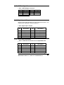
3.15 CompactFlash Storage Card Socket
The NOVA-3710/3710SV configures CompactFlash Card in IDE
Mode. It will use IDE Secondary when CompactFlash card is
plugged in.
• CN27 : CompactFlash Storage Card Socket pin assignment
PIN NO
1
2
3
4
5
6
7
8
9
10
11
12
13
14
15
16
17
DESCRIPTION
GROUND
D3
D4
D5
D6
D7
CS1#
N/C
GROUND
N/C
N/C
N/C
VCC
N/C
N/C
N/C
N/C
PIN NO
26
27
28
29
30
31
32
33
34
35
36
37
38
39
40
41
42
DESCRIPTION
CARD DETECT1
D11
D12
D13
D14
D15
CS3#
N/C
IOR#
IOW#
OBLIGATORY TO PULL HIGH
IRQ15
VCC
MASTER/SLAVE
N/C
RESET#
IORDY
NOVA-3710/3710SV Socket 370 CeleronTM & Pentium III ®
Multimedia & Dual VGA , Ethernet Embedded Board
25
18
19
20
21
22
23
24
25
A2
A1
A0
D0
D1
D2
N/C
CARD DETECT2
43
44
45
46
47
48
49
50
N/C
OBLIGATORY TO PULL HIGH
ACTIVE#
PDIAG#
D8
D9
D10
GROUND
3.16 Power Connector
The NOVA-3710/3710SV can work without back-plane , while
attaching external power to this connector .
• CN25: Power Supply Connector
Pin No.
Description
1
2
3
4
5
6
7
8
VCC
VCC
5VSB
12V
PSON#
GND
GND
GND
NOVA-3710/3710SV Socket 370 CeleronTM & Pentium III ®
Multimedia & Dual VGA , Ethernet Embedded Board
26
3.17 LCD Backlight Connector
• CN4 : LCD Backlight Connector
Pin No.
1
3
5
Description Pin No.
NC
GND
GND
2
4
Description
ENABKL
+12V
3.18 Digital Input / Output
NOVA-3710/3710SV provides you with an digital input/output. The
usage will be explained in detail in appendix .
• CN2 : Digital Input / Output
Pin
1
3
5
7
9
Description
Input 0
Input 2
Output 0
Output 2
GND
Pin
2
4
6
8
10
Description
Input 1
Input 3
Output 1
Output 3
VCC
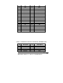
3.19 LCD Panel Connector
• CN14 : LCD Panel Connector for On chip SIS300 VGA
Pin
1
3
5
7
9
Description
NC
NC
NC
NC
NC
Pin
2
4
6
8
10
Description
NC
NC
NC
NC
NC
NOVA-3710/3710SV Socket 370 CeleronTM & Pentium III ®
Multimedia & Dual VGA , Ethernet Embedded Board
27
11
13
15
17
19
21
23
25
27
29
31
33
35
37
39
41
43
45
47
49
NC
NC
P23
P16
P17
P19
P13
P15
P7
VDD
P9
P4
P3
P2
M
SHFCLK
FPVDD
FPVEE
GND
+12V
12
14
16
18
20
22
24
26
28
30
32
34
36
38
40
42
44
46
48
50
NC
P21
P22
P20
P18
P14
P12
P11
P10
VDD
P8
P6
P5
P1
P0
ENABLK
FLM
LP
GND
+12V
• CN13 : LCD Panel Connector for On Board C&T69000 VGA
Pin
1
3
5
7
Description
+12V
GND
PVCC
ENAVEE
Pin
2
4
6
8
Description
+12V
GND
PVCC
GND
NOVA-3710/3710SV Socket 370 CeleronTM & Pentium III ®
Multimedia & Dual VGA , Ethernet Embedded Board
28
9
11
13
15
17
19
21
23
25
27
29
31
33
35
37
39
41
43
P0
P2
P4
P6
P8
P10
P12
P14
P16
P18
P20
P22
GND
SHCLK
M
GND
N/C
VCLK
10
12
14
16
18
20
22
24
26
28
30
32
34
36
38
40
42
44
P1
P3
P5
P7
P9
P11
P13
P15
P17
P19
P21
P23
GND
FLM
LP
ENABKL
N/C
3.20 IO Connector
• SL1 : IO Connector
Pin
1
3
5
7
9
11
13
Description
EAROUT_L
DIO_OUT01
COM4_DTR
COM4_RTS
EAROUT_R
COM2_CTS
COM2_DSR
Pin
2
4
6
8
10
12
14
Description
DIO_IN00
DIO_OUT00
COM4_DSR
COM4_CTS
COM4_SOUT
COM2_RI
COM2_RTS
NOVA-3710/3710SV Socket 370 CeleronTM & Pentium III ®
Multimedia & Dual VGA , Ethernet Embedded Board
29
15
17
19
21
23
25
27
29
31
33
35
37
39
41
43
45
47
49
51
53
55
57
59
COM2_SOUT
COM2_DCD
COM1_CTS
COM1_DSR
COM1_SOUT
COM1_DCD
K/B_CLK
MOUSE_CLK
USB_1+
USB_0+
COM4_SIN
PRT_D0
PRT_D2
PRT_D4
PRT_D6
PRT_ACK#
PRT_BUSY
PRT_AED#
PRT_INIT#
LAN_L78
LAN_L45
LAN_TX+
LAN_TX-
16
18
20
22
24
26
28
30
32
34
36
38
40
42
44
46
48
50
52
54
56
58
60
COM2_DTR
COM2_SIN
COM1_RI
COM1_RTS
COM1_DTR
COM1_SIN
K/B_DATA
MOUSE_DATA
USB_1USB_0PRT_STB#
PRT_D1
PRT_D3
PRT_D5
PRT_D7
PRT_PE
PRT_SLCT
PRT_ERR#
PRT_SLIN
LAN_L78
LAN_L45
LAN_RX+
LAN_TX+
NOVA-3710/3710SV Socket 370 CeleronTM & Pentium III ®
Multimedia & Dual VGA , Ethernet Embedded Board
30
4
AWARD BIOS SETUP
4.1 Introduction
This discusses the Award BIOS Setup program built into the ROM BIOS. The
Setup program allows users to modify the basic system configuration. The
changed information is then stored in battery-backed RAM so that it retains the
Setup information when the power is turned off.
4.2 Starting Setup
The Award BIOS is immediately activated when you first power on the computer.
The BIOS reads the system information contained in the CMOS and begins the
process of checking out the system and configuring it. When it finishes, the BIOS
will seek an operating system on one of the disks and then launch and turn
control over to the operating system.
While the BIOS is in control, the Setup program can be activated in one of two
ways:
1. By pressing <Del> immediately after switching the system on, or
2. by pressing the <Del> key when the following message appears briefly at the
bottom of the screen during the POST (Power On Self Test).
Press DEL to enter SETUP.
If the message disappears before you respond and you still wish to enter Setup,
restart the system to try again by turning it OFF then ON or pressing the "RESET"
button on the system case. You may also restart by simultaneously pressing
<Ctrl>, <Alt>, and <Delete> keys. If you do not press the keys at the correct time
and the system does not boot, an error message will be displayed and you will
again be asked to...
NOVA-3710/3710SV Socket 370 CeleronTM & Pentium III ®
Multimedia & Dual VGA , Ethernet Embedded Board
31
PRESS F1 TO CONTINUE, DEL TO ENTER SETUP
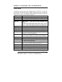
Using Setup
In general, you use the arrow keys to highlight items, press <Enter> to select, use
the PageUp and PageDown keys to change entries, press <F1> for help and
press <Esc> to quit. The following table provides more detail about how to
navigate in the Setup program using the keyboard.
Up arrow
Down arrow
Left arrow
Right arrow
Esc key
PgUp key
PgDn key
+ key
- key
F1 key
(Shift)F2 key
F3 key
F4 key
Move to previous item
Move to next item
Move to the item in the left hand
Move to the item in the right hand
Main Menu -- Quit and not save changes into
CMOS
Status Page Setup Menu and Option Page Setup
Menu -- Exit current page and return to Main Menu
Increase the numeric value or make changes
Decrease the numeric value or make changes
Increase the numeric value or make changes
Decrease the numeric value or make changes
General help, only for Status Page Setup Menu
and Option Page Setup Menu
Change color from total 16 colors. F2 to select
color forward, (Shift) F2 to select color backward
Calendar, only for Status Page Setup Menu
Reserved
F5 key
Restore the previous CMOS value from CMOS, only
for Option Page Setup Menu
F6 key
Load the default CMOS value from BIOS default
table, only for Option Page Setup Menu
Load the default
Reserved
Reserved
Save all the CMOS changes, only for Main Menu
F7 key
F8 key
F9 key
F10 key
NOVA-3710/3710SV Socket 370 CeleronTM & Pentium III ®
Multimedia & Dual VGA , Ethernet Embedded Board
32
4.4
Getting Help
Press F1 to pop up a small help window that describes the appropriate keys to
use and the possible selections for the highlighted item. To exit the Help Window
press <Esc> or the F1 key again.
If, after making and saving system changes with Setup, you discover that your
computer no longer is able to boot, the Award BIOS supports an override to the
CMOS settings which resets your system to its defaults.
The best advice is to alter settings which you thoroughly understand. We
strongly recommend that you avoid making any changes to the chipset default
settings. These default settings were carefully chosen by both Award and your
systems manufacturer to provide the absolute maximum performance and
reliability. Even a seemingly small change to the chipset setup has the potential
of causing you to use the override.
NOVA-3710/3710SV Socket 370 CeleronTM & Pentium III ®
Multimedia & Dual VGA , Ethernet Embedded Board
33
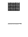
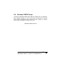
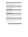
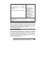
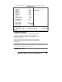
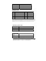
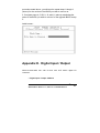
4.5 Main Menu
Once you enter the AwardBIOS™ CMOS Setup Utility, the Main Menu will
appear on the screen. The Main Menu allows you to select from several
setup functions and two exit choices. Use the arrow keys to select
among the items and press <Enter> to accept and enter the sub-menu.
CMOS Setup Utility - Copyright ( C ) 1984-1998
Standard CMOS Feature
Frequency/Voltage Control
Advanced BIOS Feature
Load Fail-Safe Defaults
Advanced Chipset Feature
Load Optimized Defaults
Integrated Peripherals
Set Supervisor Password
Power Management Setup
Set User Password
PnP/PCI Configurations
Save & Exit Setup
PC Health Status
Exit Without Saving
Esc : Quit
↑ ↓ ← → : Select Item
F10 : Save & Exit Setup
Time, Date, Hard Disk Type….
Note that a brief description of each highlighted selection appears at the
bottom of the screen.
The main menu includes the following main setup categories. Recall that
some systems may not include all entries.
Standard CMOS Features
NOVA-3710/3710SV Socket 370 CeleronTM & Pentium III ®
Multimedia & Dual VGA , Ethernet Embedded Board
34
Use this menu for basic system configuration. See Section 4.6 for the
details.
Advanced BIOS Features
Use this menu to set the Advanced Features available on your system.
See Section 4.7 for the details.
Advanced Chipset Features
Use this menu to change the values in the chipset registers and optimize
your system's performance. See section 4.8 for the details.
Integrated Peripherals
Use this menu to specify your settings for integrated peripherals. See
section 4.9 for the details.
Power Management Setup
Use this menu to specify your settings for power management. See
section 4.10 for the details.
PnP / PCI Configuration
This entry appears if your system supports PnP / PCI. See section 4.11
for the details.
PC Health Status
Use this menu to monitor your hardware. See section 4.12 for the details.
Frequency/Voltage Control
Use this menu to specify your settings for frequency/voltage control. See
section 4.13 for the details.
Load Fail-Safe Defaults
NOVA-3710/3710SV Socket 370 CeleronTM & Pentium III ®
Multimedia & Dual VGA , Ethernet Embedded Board
35
Use this menu to load the BIOS default values for the minimal/stable
performance for your system to operate. See section 4.14 for the details.
Load Optimized Defaults
Use this menu to load the BIOS default values that are factory settings for
optimal performance system operations. While Award has designed the
custom BIOS to maximize performance, the factory has the right to
change these defaults to meet their needs. See section 4.14 for the
details.
Supervisor / User Password
Use this menu to set User and Supervisor Passwords. See section 4.15
for the details.
Save & Exit Setup
Save CMOS value changes to CMOS and exit setup. See section 4.16
for the details.
Exit Without Save
Abandon all CMOS value changes and exit setup. See section 4.16 for
the details.
NOVA-3710/3710SV Socket 370 CeleronTM & Pentium III ®
Multimedia & Dual VGA , Ethernet Embedded Board
36
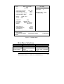
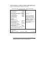
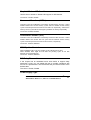
4.6 Standard CMOS Setup
The items in Standard CMOS Setup Menu are divided into 10 categories.
Each category includes no, one or more than one setup items. Use the
arrow keys to highlight the item and then use the <PgUp> or <PgDn>
keys to select the value you want in each item.
.
Standard CMOS Features
NOVA-3710/3710SV Socket 370 CeleronTM & Pentium III ®
Multimedia & Dual VGA , Ethernet Embedded Board
37
Date:
Time:
¾
¾
¾
¾
Mon, Feb 8 1999
16:19:20
IDE Primary Master
IDE Primary Slave
IDE Secondary Master
IDE Secondary Slave
Drive A
Drive B
2557 MB
None
None
None
Item Help
Menu Level
¾
Change the day, month,
year and century
1.44M, 3.5 in.
None
LCD&CRT
C&T Panel:
630 Panel :
Halt On
Both
800x600 TFT
Hardware Setting
All Errors
Based Memory
Extended Memory
Total Memory
640K
64512K
65536K
↑↓←→Move Enter: Select +/-/PU/PD: Value F10:Save ESC: Exit
F1:General Help
F5:Previous Values
F6:Fail-safe defaults
F7:Optimized
Defaults
Figure 1: The Main Menu
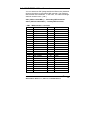
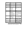
Main Menu Selections
Item
Date
Time
IDE
Primary Master
Options
MM DD YYYY
HH : MM : SS
Options are in its sub
menu
(described in Table 3)
Description
Set the system date.
Set the system time
Press <Enter> to enter
the sub menu of detailed
options
NOVA-3710/3710SV Socket 370 CeleronTM & Pentium III ®
Multimedia & Dual VGA , Ethernet Embedded Board
38
IDE
Primary Slave
Base Memory
Options are in its sub
menu
(described in Table 3)
Options are in its sub
menu
(described in Table 3)
Options are in its sub
menu
(described in Table 3)
None
360K, 5.25 in
1.2M, 5.25 in
720K, 3.5 in
1.44M, 3.5 in
2.88M, 3.5 in
Both
CRT
Hardware Setting
800x600 TFT1
800x600 TFT2
1024x768 18bit TFT1
1024x768 18bit TFT2
1024x768 18bit TFT3
1024x768 18bit TFT4
1024x768 24bit TFT
All Errors
No Errors
All, but Keyboard
All, but Diskette
All, but Disk/Key
N/A
Extended Memory
N/A
Total Memory
N/A
IDE
Secondary Master
IDE
Secondary Master
Drive A
Drive B
LCD&CRT
Panel
Halt On
Press <Enter> to enter
the sub menu of detailed
options
Press <Enter> to enter
the sub menu of detailed
options
Press <Enter> to enter
the sub menu of detailed
options
Select the type of floppy
disk drive installed in your
system
Select LCD & CRT
Display
Select Panel Type. Every
type is predefined with a
special timing. You may
try each setting according
to your LCD. However,
not every kind of LCD will
be supported.
Select the situation in
which you want the BIOS
to
stop
the
POST
process and notify you
Displays the amount of
conventional
memory
detected during boot up
Displays the amount of
extended
memory
detected during boot up
Displays the total memory
available in the system
NOVA-3710/3710SV Socket 370 CeleronTM & Pentium III ®
Multimedia & Dual VGA , Ethernet Embedded Board
39
Table 2 Main Menu Selections
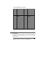
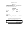
IDE Adapters
The IDE adapters control the hard disk drive. Use a separate sub menu
to configure each hard disk drive.
Figure 2 shows the IDE primary master sub menu.
CMOS Setup Utility – Copyright © 1984-1998 Award Software
IDE Primary Master
IDE HDD Auto-Detection
Press Enter
Item Help
IDE Primary Master
Access Mode
Cylinder
Head
Precomp
Landing Zone
Sector
Auto 2557 MB
Auto
4956
16
0
4955
63
Menu Level
¾¾
To auto-detect the HDD’s
size, head... on this
channel
↑↓←→Move
Enter: Select +/-/PU/PD: Value
F1:General Help
F5:Previous Values
F6:Fail-safe defaults
Defaults
F10:Save
ESC: Exit
F7:Optimized
Figure 2 IDE Primary Master sub menu
Use the legend keys to navigate through this menu and exit to the
main menu. Use Table 3 to configure the hard disk.
Item
IDE HDD Auto-detection
Options
Press Enter
Description
Press Enter to auto-detect
the HDD on this channel. If
detection is successful, it fills
NOVA-3710/3710SV Socket 370 CeleronTM & Pentium III ®
Multimedia & Dual VGA , Ethernet Embedded Board
40
IDE Primary Master
None
Auto
Manual
Capacity
Auto
Display
your disk drive
size
Access Mode
the remaining fields on this
menu.
Selecting ‘manual’ lets you
set the remaining fields on
this screen. Selects the type
of fixed disk. "User Type"
will let you select the number
of cylinders, heads, etc.
Note:
PRECOMP=65535
means NONE !
Disk
drive
capacity
(Approximated). Note that
this size is usually slightly
greater than the size of a
formatted disk given by a
disk checking program.
Choose the access mode for
this hard disk
Normal
LBA
Large
Auto
The following options are selectable only if the ‘IDE Primary Master’ item is
set to ‘Manual’
Cylinder
Min = 0
Set the number of cylinders
Max = 65535
for this hard disk.
Head
Min = 0
Set the number of read/write
Max = 255
heads
Precomp
Min = 0
**** Warning: Setting a value
Max = 65535
of 65535 means no hard disk
Landing zone
Min = 0
****
Max = 65535
Sector
Min = 0
Number of sectors per track
Max = 255
Table 3 Hard disk selections
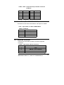
4.7 Advanced BIOS Features
NOVA-3710/3710SV Socket 370 CeleronTM & Pentium III ®
Multimedia & Dual VGA , Ethernet Embedded Board
41
This section allows you to configure your system for basic operation. You
have the opportunity to select the system’s default speed, boot-up
sequence, keyboard operation, shadowing and security.
CMOS Setup Utility – Copyright © 1984 – 1998 Award Software
Advanced BIOS Features
Item Help
Virus Warning
Enabled
CPU Internal Cache
Enabled _______________________
External Cache
Enabled ____________
CPU L2 Cache ECC Checking Enabled
¾
Quick Power On Self Test
Disabled Menu Level
First Boot device
Floppy
Allows you to choose the
Second Boot device
HDD-0
Third Boot device
Floppy VIRUS warning feature for
IDE Hard Disk boot sector
Boot other device
protection. If this function is
Disabled
enabled and someone
Swap Floppy Drive
attempt to write data into this
Disabled
Boot Up Floppy Seek
Disabled area, BIOS will show a
warning message on screen
Boot Up NumLock Status
Off
Gate A20 Option
Normal and alarm beep
Typematic Rate Setting
Disabled
Typematic Rate (Chars/Sec)
6
Typematic Delay (Msec)
250
Security Option
Setup
OS Select For DRAM > 64MB Non-OS2
Report NO FDD For Win 95
No
↑↓←→Move Enter: Select +/-/PU/PD: Value F10:Save ESC: Exit
F1:General Help
F5:Previous Values
F6:Fail-safe defaults
F7:Optimized
Defaults
NOVA-3710/3710SV Socket 370 CeleronTM & Pentium III ®
Multimedia & Dual VGA , Ethernet Embedded Board
42
Virus Warning
Allows you to choose the VIRUS Warning feature for IDE Hard Disk boot
sector protection. If this function is enabled and someone attempt to
write data into this area, BIOS will show a warning message on screen
and alarm beep.
Enabled
Activates automatically when the system boots up
causing a warning message to appear when anything
attempts to access the boot sector or hard disk partition
table.
Disabled
No warning message will appear when anything
attempts to access the boot sector or hard disk partition
table.
CPU Internal Cache/External Cache
These two categories speed up memory access. However, it depends on
CPU/chipset design.
Enabled
Enable cache
Disabled
Disable cache
CPU L2 Cache ECC Checking
This item allows you to enable/disable CPU L2 Cache ECC checking.
The choice: Enabled, Disabled.
Processor Number Feature
Some of the new generation of socket-370 processors are installed with a
unique processor number. This number may be used for verification in
internet transactions and e-commerce. If you prefer not to use or
distribute the unique processor number , use this item to suppress the
processor number. The Choice : Enable , Disable.
NOVA-3710/3710SV Socket 370 CeleronTM & Pentium III ®
Multimedia & Dual VGA , Ethernet Embedded Board
43
Quick Power On Self Test
This category speeds up Power On Self Test (POST) after you power up
the computer. If it is set to Enable, BIOS will shorten or skip some check
items during POST.
Enabled
Enable quick POST
Disabled
Normal POST
First/Second/Third/Other Boot Device
The BIOS attempts to load the operating system from the devices in the
sequence selected in these items.
The Choice: Floppy, LS/ZIP, HDD, SCSI, CDROM, Disabled.
Swap Floppy Drive
If the system has two floppy drives, you can swap the logical drive name
assignments.
The choice: Enabled/Disabled.
Boot Up Floppy Seek
Seeks disk drives during boot up. Disabling speeds boot up.
The choice: Enabled/Disabled.
Boot Up NumLock Status
Select power on state for NumLock.
The choice: Enabled/Disabled.
Gate A20 Option
Select if chipset or keyboard controller should control GateA20.
NOVA-3710/3710SV Socket 370 CeleronTM & Pentium III ®
Multimedia & Dual VGA , Ethernet Embedded Board
44
Normal
Fast
A pin in the keyboard controller
GateA20
Lets chipset control GateA20
controls
Typematic Rate Setting
Key strokes repeat at a rate determined by the keyboard controller.
When enabled, the typematic rate and typematic delay can be selected.
The choice: Enabled/Disabled.
Typematic Rate (Chars/Sec)
Sets the number of times a second to repeat a key stroke when you hold
the key down.
The choice: 6, 8, 10, 12, 15, 20, 24, 30.
Typematic Delay (Msec)
Sets the delay time after the key is held down before it begins to repeat
the keystroke.
The choice: 250, 500, 750, 1000.
Security Option
Select whether the password is required every time the system boots or
only when you enter setup.
System
The system will not boot and access to Setup will be
denied if the correct password is not entered at the
prompt.
Setup
The system will boot, but access to Setup will be denied if
the correct password is not entered at the prompt.
Note: To disable security, select PASSWORD SETTING at Main Menu
and then you will be asked to enter password. Do not type anything and
just press <Enter>, it will disable security. Once the security is disabled,
the system will boot and you can enter Setup freely.
OS Select For DRAM > 64MB
NOVA-3710/3710SV Socket 370 CeleronTM & Pentium III ®
Multimedia & Dual VGA , Ethernet Embedded Board
45
Select the operating system that is running with greater than
64MB of RAM on the system.
The choice: Non-OS2, OS2.
Report No FDD For Win 95
Whether report no FDD for Win 95 or not.
The choice: Yes, No.
Video BIOS Shadow
This item allows the video BIOS to be copied to system memory for
faster performance.
The Choice : Enable , Disable.
4.8 Advanced Chipset Features
CMOS Setup Utility – Copyright © 1984 – 1998 Award Software
Advanced Chipset Features
NOVA-3710/3710SV Socket 370 CeleronTM & Pentium III ®
Multimedia & Dual VGA , Ethernet Embedded Board
46
Advanced DRAM Control 1 Press Enter
Advanced DRAM Control 2 Press Enter
Item Help
_______________________
____________
System BIOS Cacheable
Disabled Menu Level
¾
Video BIOS Cacheable
Disabled
Memory Hole At 15M-16M
Enabled
AGP Aperture Size
64MB
Graphic Window WR Combin Enable
Concurrent function ( MEM )
Enabled
Concurrent function ( PCI )
Enabled
CPU Pipeline Control
Enabled
PCI Delay Transaction
Enabled
Power-supply Type
AT
Memory Parity Check
Enabled
↑↓←→Move Enter: Select +/-/PU/PD: Value F10:Save ESC: Exit
F1:General Help
F5:Previous Values
F6:Fail-safe defaults
F7:Optimized
Defaults
This section allows you to configure the system based on the specific
features of the installed chipset. This chipset manages bus speeds and
access to system memory resources, such as DRAM and the external
cache. It also coordinates communications between the conventional ISA
bus and the PCI bus. It must be stated that these items should never
need to be altered. The default settings have been chosen because they
provide the best operating conditions for your system.
Advanced DRAM Control 1 / 2 Settings
The first chipset settings deal with CPU access to dynamic random
access memory (DRAM). The default timings have been carefully chosen
and should only be altered if data is being lost. Such a scenario might
well occur if your system had mixed speed DRAM chips installed so that
greater delays may be required to preserve the integrity of the data held
in the slower memory chips.
Auto Configuration
NOVA-3710/3710SV Socket 370 CeleronTM & Pentium III ®
Multimedia & Dual VGA , Ethernet Embedded Board
47
This item will automatically configure the chipset timing. . You may select 'manual'
to set up following gray items by your specific need.
The choice: Manual, Auto, 100MHZ, 133MHZ.
SDRAM RAS Active Time
This item defines SDRAM ACT to PRE command period.
The Choice: 6T, 7T, 5T, 4T.
SDRAM RAS Precharge Time
This item defines SDRAM PRE to ACT command period.
The Choice: 3T, 2T, 4T, Reserved.
RAS to CAS Delay
This item defines SDRAM ACT to Read/Write command period.
The choice: 3T, 2T, 4T, Reserved.
Dram Backgroud Command
This item is lead-off time control for DRAM background command. When select
'Delay 1T' , background commands are issued 1 clock behind memory address
(MA) been issued. When select 'Normal', background command and MA are
issued at the same time.
The choice: Delay 1T, Normal.
LD-Off Dram RD/WR Cycles
The item is lead-off time control for DRAM Read/Write Cycles. When select
'Delay 1T' , memory read/write command is issued 1 clock behind memory
address (MA) been issued. When select 'Normal', read/write command and MA
are issued at the same time.
The choice: Delay 1T, Normal.
Write Recovery Time
NOVA-3710/3710SV Socket 370 CeleronTM & Pentium III ®
Multimedia & Dual VGA , Ethernet Embedded Board
48
This item defines the Data-in to PRE command period.
The choice: 1T, 2T
VCM REF To ACT/REF Delay
This item defines VCM REF to REF/ACT command period.
The choice: 10T, 9T.
VCM ACCT To ACT/REF Delay
This item defines VCM ACT to ACT/REF command period.
The choice: 10T, 9T, 8T, Reserved.
Early CKE Delay 1T Cntrl
When this item is enabled, CKE is driven out from flip-flop. It is used when
system operates under low frequency and CKE delay adjustment method defined
in the 'Early CKE Delay Adjustment' which can not meet setup time and hold time
requirement.
The choice: Normal, Delay 1T.
Early CKE Delay Adjust
This item controls the timing for CKE. Various delay options are provided to
ensure that CKE can meet SDRAM setup time and hold time specification when
CKE is driven out.
The Choice: 1ns, 2ns, 3ns, 4ns, 5ns, 6ns, 7ns, 8ns.
Mem Command Output Time
This item is to control the timing to drive memory command onto memory bus.
The choice: Normal, Delay 1T.
SDRAM/VCM CAS Latency
NOVA-3710/3710SV Socket 370 CeleronTM & Pentium III ®
Multimedia & Dual VGA , Ethernet Embedded Board
49
When synchronous DRAM is installed, the number of clock cycles of CAS latency
depends on the DRAM timing.
The Choice: 2, 3 , SPD
SDRCLK Control
This item controls the phase of SDRCLK that lags behind SDCLK.
The choice: Enabled, Disabled.
SDWCLK Control CS#/CKE
This item controls the phase of SDWCLK used for chip set select signals pin that
lags ahead SDCLK.
The choice: Enabled, Disabled.
SDWCLK Control MA/SRAS
This item controls the phase of SDWCLK used for MA/ SRAS signals that lags
ahead SDCLK.
The choice: +5.0ns~-2.5ns (Default 0.0ns)
SDWCLK Control DQM/MD
This item controls the phase of SDWCLK used for DQM/MD signals that lags
ahead SDCLK.
The choice: +5.0ns~-2.5ns (Default 0.0ns)
EGMRCLK Control
This item controls the phase of EGMRCLK that lags behind SDCLK.
The choice: -1.0ns~+6.5ns (Default 0.0ns)
NOVA-3710/3710SV Socket 370 CeleronTM & Pentium III ®
Multimedia & Dual VGA , Ethernet Embedded Board
50
EGMWCLK Control
This item controls the phase of EGMWCLK that lags ahead SDCLK.
The choice: +5.0ns~-2.5ns (Default 0.0ns)
System BIOS Cacheable
Selecting Enabled allows caching of the system BIOS ROM at F0000h-FFFFFh,
resulting in better system performance. However, if any program writes to this
memory area, a system error may result.
The choice: Enabled, Disabled.
Vedio RAM Cacheable
Select Enabled allows caching of the video RAM , resulting in better system
performance. However, if any program writes to this memory area, a system error
may result.
The choice: Enabled, Disabled.
Memory Hole at 15M-16M
You can reserve this area of system memory for ISA adapter ROM. When this
area is reserved, it cannot be cached. The user information of peripherals that
need to use this area of system memory usually discusses their memory
requirements.
The Choice: Enabled, Disabled.
AGP Aperture Size
Select the size of Accelerated Graphics Port (AGP) aperture. The aperture is a
portion of the PCI memory address range dedicated for graphics memory address
space. Host cycles that hit the aperture range are forwarded to the AGP without
any translation.
The Choice: 4M, 8M, 16M, 32M, 64M, 128M, 256M.
NOVA-3710/3710SV Socket 370 CeleronTM & Pentium III ®
Multimedia & Dual VGA , Ethernet Embedded Board
51
Graphic Window WR Combin
Use this item to enable or disable CPU support for WR Combin.
The Choice : Enable , Disable .
Concurrent Function ( MEM )
This item is CPU & PCI Masters Concurrently Access Memory Function. Select
enabled allows CPU access memory cycles and PCI masters access memory
cycles concurrently issued onto host bus and PCI bus, respectively, and then the
memory access cycles will be rearranged by SIS630S to memory sequentially.
The choice: Enabled, Disabled
Concurrent Function ( PCI )
This item is CPU & PCI Masters Concurrently Access PCI Bus Function. Select
enabled allows CPU access PCI bus cycle and PCI masters access memory
cycles concurrently issued onto host bus and PCI bus, respectively.
The choice: Enabled, Disabled.
CPU Pipeline Control
When enabled this item, only one pending cycle is allowed at one time.
When disabled, there might be more than two pending cycles at one time
depends on the CPU behavior.
The choice: Enabled, Disabled.
PCI Delay Transaction
If the chipset has an embedded 32-bit write buffer to support delay
transaction cycles, you can enable this item to provide compliance with
PCI Ver.2.1 specifications. We recommend that you leave this item at the
default value.
The choice : Enable, Disable.
Power-Supply Type
NOVA-3710/3710SV Socket 370 CeleronTM & Pentium III ®
Multimedia & Dual VGA , Ethernet Embedded Board
52
This item controls the power-supply type to AT or ATX.
The choice: AT,ATX.
Memory Parity Check
Enabled this item to test the boot-up memory. .
The choice: Enabled, Disabled.
NOVA-3710/3710SV Socket 370 CeleronTM & Pentium III ®
Multimedia & Dual VGA , Ethernet Embedded Board
53
4.9 Integrated Peripherals
CMOS Setup Utility – Copyright © 1984 – 1998 Award Software
Integrated Peripherals
Item Help
SIS 630 OnChip IDE Device Press Enter ______________________
SIS 630 OnChip PCI Device Press Enter _____________
Super I/O Device
Press
Menu Level
¾
Enter
If your IDE hard drive
supports block mode select
USB Controller
Enabled Enabled for automatic
USB Keyboard Support
Enabled detection of the optimal
Init Display First
PCI
number of block read/write
Slot
per sector the drive can
IDE HDD Block Mode
Enabled support
System Share Memory
8MB
↑↓←→ Move Enter: Select +/-/PU/PD: Value F10:Save ESC: Exit
F1:General Help
F5:Previous Values
F6:Fail-safe defaults
F7:Optimized
Defaults
SIS 630 OnChip IDE Device
Internal PCI / IDE
This chipset contains an internal PCI IDE interface with support for two
IDE channels.
The choice: Primary, Secondary, Both.
IDE Primary Master/Slave PIO
The four IDE PIO (Programmed Input / Output) fields let you set a PIO
mode (0-4) for each of the four IDE devices that the onboard IDE
NOVA-3710/3710SV Socket 370 CeleronTM & Pentium III ®
Multimedia & Dual VGA , Ethernet Embedded Board
54
interface supports. Modes 0 through 4 provide successively increased
performance. In Auto mode, the system automatically determines the
best mode for each device.
The choice: Auto, Mode 0, Mode 1, Mode 2, Mode 3, and Mode 4.
Primary Master/Slave UltraDMA
UDMA (Ultra DMA) is a DMA data transfer protocol that utilizes ATA commands
and the ATA bus to allow DMA commands to transfer data at a maximum burst
rate of 33 MB/s. When you select Auto in the four IDE UDMA fields (for each of
up to four IDE devices that the internal PCI IDE interface supports), the system
automatically determines the optimal data transfer rate for each IDE device.
The choice: Auto, Disabled.
IDE Burst Mode
Selecting Enabled reduces latency between each drive read/write cycle,
but may cause instability in IDE subsystems that cannot support such fast
performance. If you are getting disk drive errors, try setting this value to
Disabled. This field does not appear when the Internal PCI/IDE field,
above, is Disabled.
The choice: Enabled, Disabled.
SIS 630 OnChip PCI Device
SIS-7018 AC97 AUDIO
Select Enabled to support AC97 Audio.
The choice: Enabled, Disabled.
SIS-900 10/100M ETHERNET
This item provides a total communication solution including 10/100Mb Fast
Ethernet for Office requirement and 1Mb HomePNA for Home Networking.
The choice: Enabled, Disabled.
NOVA-3710/3710SV Socket 370 CeleronTM & Pentium III ®
Multimedia & Dual VGA , Ethernet Embedded Board
55
Super I/O Device
Onboard FDC Controller
Select Enabled if your system has a floppy disk controller (FDC) installed
on the system board and you wish to use it. If you install and-in FDC or
the system has no floppy drive, select Disabled in this field.
The choice: Enabled, Disabled.
Onboard Serial Port 1/ Port 2 / Port 3 / Port 4
Select an address and corresponding interrupt for the first and second
serial ports.
The choice: 3F8/IRQ4, 2E8/IRQ3, 3E8/IRQ4, 2F8/IRQ3, Disabled, Auto.
UART Mode Select
This item allows you to select UART mode.
The choice: Enabled, Disabled.
UR2 Duplex Mode
This item allows you to select the IR half/full duplex funcion.
The choice: Half, Full.
Onboard Parallel Port 1 / Port 2
This item allows you to determine access onboard parallel port controller
with which I/O address.
The choice: 3BC/IRQ7, 378/IRQ7, 278/IRQ5, Disabled.
Parallel Port Mode
Select an operating mode for the onboard parallel (printer) port. Select
Normal, Compatible, or SPP unless you are certain your hardware and
software both support one of the other available modes.
NOVA-3710/3710SV Socket 370 CeleronTM & Pentium III ®
Multimedia & Dual VGA , Ethernet Embedded Board
56
The choice: SPP, EPP, ECP, ECP+EPP.
ECP Mode Use DMA
Select a DMA channel for the parallel port for use during ECP mode.
The choice: 3, 1.
USB Controller
Select Enabled if your system contains a Universal Serial Bus (USB)
controller and you have USB peripherals.
Choices are: Enabled, Disabled.
USB Keyboard Support
Select Enabled if your system contains a Universal Serial Bus (USB)
controller and you have a USB keyboard.
Choices are: Enabled, Disabled.
IDE HDD Block Mode
Block mode is also called block transfer, multiple commands, or multiple
sector read/write. If your IDE hard drive supports block mode (most new
drives do), select Enabled for automatic detection of the optimal number
of block read/writes per sector the drive can support.
The choice: Enabled, Disabled.
Init Display First
This item allows you to decide to active which bus first (PCI Slot or AGP
first).
The choice: PCI Slot, AGP.
System Share Memory Size
This item defines the System Share Memory Size for video.
Thechoice:2MB,4MB,16MB, 32MB, 64MB, 2+2MB,
NOVA-3710/3710SV Socket 370 CeleronTM & Pentium III ®
Multimedia & Dual VGA , Ethernet Embedded Board
57
4+4MB,8+8MB,16+16MB,32+32MB
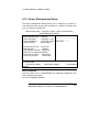
4.10 Power Management Setup
The Power Management Setup allows you to configure you system to
most effectively save energy while operating in a manner consistent with
your own style of computer use.
CMOS Setup Utility – Copyright © 1984 – 1998 Award Software
Power Management Setup
Item Help
ACPI function
Enabled
_______________________
ACPI Suspend Type S3(STR)
Video Off Option
Susp,Stby -> Off ____________
¾
Video Off Method
V/H SYNC_Blank Menu Level
Switch Function
Break/Wake
Hot Key Function As
Power Off
HDD Off After
Disable
Power Button Override Instant Off
KB Power On Password Disable
PM Wake Up Events
Press Enter
Power Up by Alarm
Press Enter
↑↓←→Move Enter: Select +/-/PU/PD: Value F10:Save ESC: Exit
F1:General Help
F5:Previous Values
F6:Fail-safe defaults
F7:Optimized
Defaults
ACPI Function
This item allows you to enable/disable the Advanced Configuration and
Power Management (ACPI).
The choice: Enabled, Disabled.
NOVA-3710/3710SV Socket 370 CeleronTM & Pentium III ®
Multimedia & Dual VGA , Ethernet Embedded Board
58
ACPI Suspend Type
This item allows you to S1(Power ON Suspend)/S3(Suspend To RAM)
the Advanced Configuration and Power Management (ACPI).
The choice: S1(POS), S3(STR).
Video Off Option
When enabled, this feature allows the VGA adapter to operate in a power saving
mode.
Always On
Monitor will remain on during power saving modes.
Suspend --> Off
Monitor blanked when the systems enters the Suspend
mode.
Susp,Stby
Off
-->
Monitor blanked when the system enters either Suspend or
Standby modes.
All Modes -->
Off
Monitor blanked when the system enters any power saving
mode.
Video Off Method
This determines the manner in which the monitor is blanked.
V/H
This selection will cause the system to turn off the vertical
SYNC+Blank
and horizontal synchronization ports and write blanks to the
video buffer.
Blank Screen
This option only writes blanks to the video buffer.
DPMS
Select this option if your monitor supports the Display
Power Management Signaling (DPMS) standard of the
Video Electronics Standards to select video power
management values.
Switch Function
NOVA-3710/3710SV Socket 370 CeleronTM & Pentium III ®
Multimedia & Dual VGA , Ethernet Embedded Board
59
You can choose whether or not to permit your system to enter complete Suspend
mode. Suspend mode offers greater power savings, with a correspondingly
longer awakening period..
The choice: Break/Wake, Disabled.
Hot Key Function As
Select Enabled if your system has a hot key for soft power off.
The choice: Enabled, Disabled.
HDD Off After
By default, this item is Disabled, meaning that no matter the mode the rest of the
system, the hard drive will remain ready. Otherwise, you have a range of choices
from 1 to 15 minutes or Suspend. This means that you can elect to have your
hard disk drive be turned off after a selected number of minutes or when the rest
of the system goes into a Suspend mode.
Power Button Over Ride
You could press the power button for more than 4 seconds forces the system to
enter the Soft-Off state when the system has “hung.”
The choice: Soft-Off, Delay 4 Sec.
PM Wake Up Events
IRQ [3-7,9-15],NMI
The following is a list of IRQ’s, Interrupt ReQuests, which can be exempted much
as the COM ports and LPT ports above can. When an I/O device wants to gain
the attention of the operating system, it signals this by causing an IRQ to occur.
When the operating system is ready to respond to the request, it interrupts itself
and performs the service.
As above, the choices are On and Off.
NOVA-3710/3710SV Socket 370 CeleronTM & Pentium III ®
Multimedia & Dual VGA , Ethernet Embedded Board
60
When set On, activity will neither prevent the system from going into a power
management mode nor awaken it.
•
IRQ [ 3-7, 9-15], NMI
•
IRQ 8 Break Suspend : You can Enable or Disable monitoring of IRQ8 (the
Real Time Clock) so it does not awaken the system from Suspend mode.
Ring / PCIPME Power Up Control
When you select Enabled, a signal from ring / PCIPME returns the system to Full
On state.
The choice: Enabled, Disabled.
KB Power On Password
This item can be used to prompt the used for a password when the system power
is resumed by keyboard action .
The choice: Disable , Enable.
Power Up by Alarm
When you select Enabled, the following fields appear. They let you set the alarm
that returns the system to Full On state.
Date ( of Month ) Alarm lets you select a day from 1 to 31 . Time Alarm lets you
select a time for the alarm in hours , minutes , and seconds .
The choice: Enabled, Disabled.
NOVA-3710/3710SV Socket 370 CeleronTM & Pentium III ®
Multimedia & Dual VGA , Ethernet Embedded Board
61
4.11 PnP/PCI Configuration Setup
This section describes configuring the PCI bus system. PCI, or Personal
Computer Interconnect, is a system which allows I/O devices to operate
at speeds nearing the speed the CPU itself uses when communicating
with its own special components. This section covers some very technical
items and it is strongly recommended that only experienced users should
make any changes to the default settings.
CMOS Setup Utility – Copyright © 1984-1998 Award Software
PnP/PCI Configurations
NOVA-3710/3710SV Socket 370 CeleronTM & Pentium III ®
Multimedia & Dual VGA , Ethernet Embedded Board
62
Reset Configuration Data Disabled
Item Help
------------------------Menu Level
¾
Auto(ESCD)
Press
Default is Disabled.
Select Enabled to reset
Extended System
PCI/VGA Palette Snoop
Disabled
Configuration
Data(ESCD) when you
exit Setup if you have
installed a new add-on
and the system
reconfiguration has
caused such a serious
conflict that the OS
cannot boot
↑↓←→Move Enter: Select +/-/PU/PD: Value F10:Save ESC: Exit
F1:General Help
F5:Previous Values
F6:Fail-safe defaults
F7:Optimized
Defaults
¾
Resources Controlled By
IRQ Resources
Enter
Reset Configuration Data
Normally, you leave this field Disabled. Select Enabled to reset Extended
System Configuration Data (ESCD) when you exit Setup if you have
installed a new add-on and the system reconfiguration has caused such a
serious conflict that the operating system can not boot.
The choice: Enabled, Disabled .
Resource controlled by
The Award Plug and Play BIOS has the capacity to automatically
configure all of the boot and Plug and Play compatible devices. However,
this capability means absolutely nothing unless you are using a Plug and
Play operating system such as Windows95. If you set this field to
“manual” choose specific resources by going into each of the sub menu
that follows this field (a sub menu is preceded by a “¾”).
The choice: Auto(ESCD), Manual.
NOVA-3710/3710SV Socket 370 CeleronTM & Pentium III ®
Multimedia & Dual VGA , Ethernet Embedded Board
63
IRQ Resources
When resources are controlled manually, assign each system interrupt a
type, depending on the type of device using the interrupt.
IRQ3/4/5/7/9/10/11/12/14/15 assigned to
This item allows you to determine the IRQ assigned to the ISA bus and is
not available to any PCI slot. Legacy ISA for devices compliant with the
original PC AT bus specification, PCI/ISA PnP for devices compliant with
the Plug and Play standard whether designed for PCI or ISA bus
architecture.
The Choice: Legacy ISA and PCI/ISA PnP.
PCI/VGA Palette Snoop
Leave this field at Disabled.
Choices are Enabled, Disabled.
4.12 PC Health Status
This section helps you to get more information about your system including CPU
temperature, FAN speed and voltages. It is recommended that you contact with
your motherboard supplier to get proper value about your setting of the CPU
temperature.
NOVA-3710/3710SV Socket 370 CeleronTM & Pentium III ®
Multimedia & Dual VGA , Ethernet Embedded Board
64
CMOS Setup Utility – Copyright © 1984-1998 Award Software
PC Health Status
Voltage 0
1.65V
Item Help
Voltage 1
2.49V
------------------------Voltage 2
3.37V
Menu Level
¾
Voltage 3
4.97V
Voltage 4
11.96V
Voltage 5
3.29V
Voltage 6
-11.45V
Voltage 7
4.65V
Voltage Battery
2.91V
Temperature1
- 55℃
Temperature2
40℃
Temperature3
79℃
FAN 1 Speed
4153 RPM
FAN 2 Speed
0 RPM
↑↓←→ Move Enter: Select +/-/PU/PD: Value F10:Save ESC: Exit
F1:General Help
F5:Previous Values
F6:Fail-safe defaults
F7:Optimized
Defaults
Voltage 0/1/2/3/4/5/6/7
The chipset reserves 8 inputs for monitoring working voltages
from various sources in the system. These voltages may
includes CPU voltage, power pins of the ATX power (+/-12V, +/5V, 3.3V...) and others.
Generic names (Voltage 0-9) are given to these items because
where these pins are connected depends on different platforms
you are using.
Voltage Battery
Monitor the output voltage of the a RTC battery.
Temperature 1/2/3
NOVA-3710/3710SV Socket 370 CeleronTM & Pentium III ®
Multimedia & Dual VGA , Ethernet Embedded Board
65
The chipset reserves 3 inputs for monitoring temperatures that
are typically the CPU & system temperatures.
Generic names are given for the same reason as Voltage 0-7.
Fan 1/2 Speed
The chipset reserves 2 inputs for monitoring FAN speeds in the
system. Usually, one FAN is applied to cool down the CPU and
the other one is applied by different purpose.
Generic names are given for the same reason as Voltage 0-7.
4.13 Frequency/Voltage Control
CMOS Setup Utility – Copyright © 1984-1998 Award Software
NOVA-3710/3710SV Socket 370 CeleronTM & Pentium III ®
Multimedia & Dual VGA , Ethernet Embedded Board
66
Frequency/Voltage Control
Auto Detect DIMM/PCI Clk
Disabled
Item Help
Spread Spectrum
Disabled ------------------------CPU HOST/SDRAM/PCI Clock Default
Menu Level
¾
CPU Clock Ratio
By H/W
↑↓←→ Move Enter: Select +/-/PU/PD: Value F10:Save ESC: Exit
F1:General Help
F5:Previous Values
F6:Fail-safe defaults
F7:Optimized
Defaults
Auto Detect DIMM/PCI CLK
This item allows you to enable/disable auto detect DIMM/PCI Clock.
The choice: Enabled, Disabled.
Spread Spectrum
This item allows you to enable/disable the spread spectrum modulate.
The choice: Enabled, Disabled.
CPU Host/DRAM/PCI Clock
This item allows you to select CPU/PCI frequency.
The choice: Default, 66/66/33MHz, 133/133/33MHz, 100/100/33MHz.
CPU Clock Ratio
NOVA-3710/3710SV Socket 370 CeleronTM & Pentium III ®
Multimedia & Dual VGA , Ethernet Embedded Board
67
This item allows you to select CPU clock ratio.
The choice: By H/W 3, 3.5, 4, 4.5, 5, 5.5, 6, 6.5, 7, 7.5, 8.
4.14 Defaults Menu
Selecting “Defaults” from the main menu shows you two options
which are described below
Load Fail-Safe Defaults
When you press <Enter> on this item you get a confirmation
dialog box with a message similar to:
Load Fail-Safe Defaults (Y/N) ? N
Pressing ‘Y’ loads the BIOS default values for the most stable,
minimal-performance system operations.
Load Optimized Defaults
When you press <Enter> on this item you get a confirmation
dialog box with a message similar to:
Load Optimized Defaults (Y/N) ? N
Pressing ‘Y’ loads the default values that are factory settings for
optimal performance system operations.
NOVA-3710/3710SV Socket 370 CeleronTM & Pentium III ®
Multimedia & Dual VGA , Ethernet Embedded Board
68
4.15 Supervisor/User Password Setting
You can set either supervisor or user password, or both of then. The
differences between are:
supervisor password :
can enter and change the options of the setup menus.
user password
:
just can only enter but do not have the right to change the options of the
setup menus. When you select this function, the following message will
appear at the center of the screen to assist you in creating a password.
ENTER PASSWORD:
Type the password, up to eight characters in length, and press <Enter>.
The password typed now will clear any previously entered password from
CMOS memory. You will be asked to confirm the password. Type the
password again and press <Enter>. You may also press <Esc> to abort
the selection and not enter a password.
To disable a password, just press <Enter> when you are prompted to
enter the password. A message will confirm the password will be
disabled. Once the password is disabled, the system will boot and you
can enter Setup freely.
PASSWORD DISABLED.
When a password has been enabled, you will be prompted to enter it
every time you try to enter Setup. This prevents an unauthorized person
from changing any part of your system configuration.
Additionally, when a password is enabled, you can also require the BIOS
to request a password every time your system is rebooted. This would
prevent unauthorized use of your computer.
You determine when the password is required within the BIOS Features
Setup Menu and its Security option (see Section 3). If the Security option
is set to password will be required both at boot and at entry to Setup. If
set to “Setup”, prompting only occurs when trying to enter Setup.
NOVA-3710/3710SV Socket 370 CeleronTM & Pentium III ®
Multimedia & Dual VGA , Ethernet Embedded Board
69
4.16 Exit Selecting
Save & Exit Setup
Pressing <Enter> on this item asks for confirmation:
Save to CMOS and EXIT (Y/N)? Y
Pressing “Y” stores the selections made in the menus in CMOS –
a special section of memory that stays on after you turn your
system off. The next time you boot your computer, the BIOS
configures your system according to the Setup selections stored
in CMOS. After saving the values the system is restarted again.
Exit Without Saving
Pressing <Enter> on this item asks for confirmation:
Quit without saving (Y/N)? Y
This allows you to exit Setup without storing in CMOS any change.
The previous selections remain in effect. This exits the Setup
utility and restarts your computer.
NOVA-3710/3710SV Socket 370 CeleronTM & Pentium III ®
Multimedia & Dual VGA , Ethernet Embedded Board
70
Appendix A. Watch-Dog Timer
The Watchdog Timer is a device ensures the standalone systems can
always recover from abnormal conditions that cause the system to crash.
These conditions may result from an external EMI or a software bug.
When the system stops working, hardware on the board will perform
hardware reset (cold boot) to bring the system back to a known state.
Three I/O ports control the operation of Watch-Dog Timer.
440 (hex)
Write
440 (hex)
Write
Set Watchdog Time period
Enable the refresh the Watchdog Timer.
Disable the Watch-Dog Timer.
Prior to enable the Watch-Dog Timer, user has to set the time-out period.
The resolution of the timer is 1 minute and the range of the timer is from 1
min to 255 min. You need to send the time-out value to the I/O port –
440H, and then enable it by write data from the same I/O port –
440H( value is 01h-ffh ). This will activate the timer that will eventually time
out and reset the CPU board. To ensure that this reset condition won’t
occur, the Watch-Dog Timer must be periodically refreshed by write the
same I/O port 440H( the same value is 01h-ffh ). This must be done within
the time-out period, please refer to the example program. Finally, we
have to disable the Watch-Dog timer by write the I/O port -- 440H ( value
is 0h ). Otherwise the system could reset unconditionally.
• Watch-Dog Timer Type Setting By RESET
• Write port 440 : WDT Enable & Time-out Period
PERIOD
Value
1 – 255 min.
01 – FF
NOVA-3710/3710SV Socket 370 CeleronTM & Pentium III ®
Multimedia & Dual VGA , Ethernet Embedded Board
71
• Write port 440 : WDT Disable
Function
Value
Disable
00
Example assembly program:
WDT_PORT = 440H
;;INITIAL TIMER COUNTER
MOV DX, WDT_PORT
MOV AL, 1 ;;1 minute
OUT DX, AL ;;start counter
W_LOOP:
MOV DX, WDT_PORT
MOV AL, 0
OUT DX, AL ;;stop counter
MOV DX, WDT_PORT
MOV AL, 1
OUT DX, AL ;;restart counter
;;ADD YOUR APPLICATION HERE
CMP EXIT_AP, 0
JNE W_LOOP
MOV DX, WDT_PORT
MOV AL, 0
OUT DX, AL
;;EXIT AP
NOVA-3710/3710SV Socket 370 CeleronTM & Pentium III ®
Multimedia & Dual VGA , Ethernet Embedded Board
72
Appendix B. POST Messages
POST Messages
During the Power On Self Test (POST), if the BIOS detects an error requiring you
to do something to fix, it will either sound a beep code or display a message.
If a message is displayed, it will be accompanied by:
PRESS F1 TO CONTINUE, CTRL-ALT-ESC OR DEL TO ENTER SETUP
POST Beep
Currently there are two kinds of beep codes in BIOS. This code indicates that a
video error has occurred and the BIOS cannot initialize the video screen to
display any additional information. This beep code consists of a single long beep
followed by three short beeps. The other code indicates that your DRAM error
has occurred. This beep code consists of a single long beep repeatedly.
Error Messages
NOVA-3710/3710SV Socket 370 CeleronTM & Pentium III ®
Multimedia & Dual VGA , Ethernet Embedded Board
73
One or more of the following messages may be displayed if the BIOS detects an
error during the POST. This list includes messages for both the ISA and the
EISA BIOS.
CMOS BATTERY HAS FAILED
CMOS battery is no longer functional. It should be replaced.
CMOS CHECKSUM ERROR
Checksum of CMOS is incorrect. This can indicate that CMOS has become
corrupt. This error may have been caused by a weak battery. Check the battery
and replace if necessary.
DISK BOOT FAILURE, INSERT SYSTEM DISK AND PRESS ENTER
No boot device was found. This could mean that either a boot drive was not
detected or the drive does not contain proper system boot files. Insert a system
disk into Drive A: and press <Enter>. If you assumed the system would boot from
the hard drive, make sure the controller is inserted correctly and all cables are
properly attached. Also be sure the disk is formatted as a boot device. Then
reboot the system.
DISKETTE DRIVES OR TYPES MISMATCH ERROR - RUN SETUP
Type of diskette drive installed in the system is different from the CMOS definition.
Run Setup to reconfigure the drive type correctly.
DISPLAY SWITCH IS SET INCORRECTLY
Display switch on the motherboard can be set to either monochrome or color.
This indicates the switch is set to a different setting than indicated in Setup.
Determine which setting is correct, and then either turn off the system and
change the jumper, or enter Setup and change the VIDEO selection.
DISPLAY TYPE HAS CHANGED SINCE LAST BOOT
Since last powering off the system, the display adapter has been changed. You
must configure the system for the new display type.
EISA Configuration Checksum Error
PLEASE RUN EISA CONFIGURATION UTILITY
The EISA non-volatile RAM checksum is incorrect or cannot correctly read the
EISA slot. This can indicate either the EISA non-volatile memory has become
corrupt or the slot has been configured incorrectly. Also be sure the card is
installed firmly in the slot.
NOVA-3710/3710SV Socket 370 CeleronTM & Pentium III ®
Multimedia & Dual VGA , Ethernet Embedded Board
74
EISA Configuration Is Not Complete
PLEASE RUN EISA CONFIGURATION UTILITY
The slot configuration information stored in the EISA non-volatile memory is
incomplete.
Note: When either of these errors appear, the system will
boot in ISA mode, which allows you to run the EISA
Configuration Utility.
ERROR ENCOUNTERED INITIALIZING HARD DRIVE
Hard drive cannot be initialized. Be sure the adapter is installed correctly and all
cables are correctly and firmly attached. Also be sure the correct hard drive type
is selected in Setup.
ERROR INITIALIZING HARD DISK CONTROLLER
Cannot initialize controller. Make sure the cord is correctly and firmly installed in
the bus. Be sure the correct hard drive type is selected in Setup. Also check to
see if any jumper needs to be set correctly on the hard drive.
FLOPPY DISK CNTRLR ERROR OR NO CNTRLR PRESENT
Cannot find or initialize the floppy drive controller. make sure the controller is
installed correctly and firmly. If there are no floppy drives installed, be sure the
Diskette Drive selection in Setup is set to NONE.
Invalid EISA Configuration
PLEASE RUN EISA CONFIGURATION UTILITY
The non-volatile memory containing EISA configuration information was
programmed incorrectly or has become corrupt. Re-run EISA configuration utility
to correctly program the memory.
NOTE: When this error appears, the system will boot in ISA
mode, which allows you to run the EISA Configuration
Utility.
KEYBOARD ERROR OR NO KEYBOARD PRESENT
Cannot initialize the keyboard. Make sure the keyboard is attached correctly and
no keys are being pressed during the boot.
NOVA-3710/3710SV Socket 370 CeleronTM & Pentium III ®
Multimedia & Dual VGA , Ethernet Embedded Board
75
If you are purposely configuring the system without a keyboard, set the error halt
condition in Setup to HALT ON ALL, BUT KEYBOARD. This will cause the BIOS
to ignore the missing keyboard and continue the boot.
Memory Address Error at ...
Indicates a memory address error at a specific location. You can use this location
along with the memory map for your system to find and replace the bad memory
chips.
Memory parity Error at ...
Indicates a memory parity error at a specific location. You can use this location
along with the memory map for your system to find and replace the bad memory
chips.
MEMORY SIZE HAS CHANGED SINCE LAST BOOT
Memory has been added or removed since the last boot. In EISA mode use
Configuration Utility to reconfigure the memory configuration. In ISA mode enter
Setup and enter the new memory size in the memory fields.
Memory Verify Error at ...
Indicates an error verifying a value already written to memory. Use the location
along with your system's memory map to locate the bad chip.
OFFENDING ADDRESS NOT FOUND
This message is used in conjunction with the I/O CHANNEL CHECK and RAM
PARITY ERROR messages when the segment that has caused the problem
cannot be isolated.
OFFENDING SEGMENT:
This message is used in conjunction with the I/O CHANNEL CHECK and RAM
PARITY ERROR messages when the segment that has caused the problem has
been isolated.
PRESS A KEY TO REBOOT
This will be displayed at the bottom screen when an error occurs that requires
you to reboot. Press any key and the system will reboot.
PRESS F1 TO DISABLE NMI, F2 TO REBOOT
NOVA-3710/3710SV Socket 370 CeleronTM & Pentium III ®
Multimedia & Dual VGA , Ethernet Embedded Board
76
When BIOS detects a Non-maskable Interrupt condition during boot, this will allow
you to disable the NMI and continue to boot, or you can reboot the system with
the NMI enabled.
RAM PARITY ERROR - CHECKING FOR SEGMENT ...
Indicates a parity error in Random Access Memory.
Should Be Empty But EISA Board Found
PLEASE RUN EISA CONFIGURATION UTILITY
A valid board ID was found in a slot that was configured as having no board ID.
NOTE; When this error appears, the system will boot in ISA
mode, which allows you to run the EISA Configuration
Utility.
Should Have EISA Board But Not Found
PLEASE RUN EISA CONFIGURATION UTILITY
The board installed is not responding to the ID request, or no board ID has been
found in the indicated slot.
NOTE:
When this error appears, the system will boot in
ISA mode, which allows you to run the EISA Configuration
Utility.
Slot Not Empty
Indicates that a slot designated as empty by the EISA Configuration Utility actually
contains a board.
NOTE: When this error appears, the system will boot in ISA
mode, which allows you to run the EISA Configuration
Utility.
SYSTEM HALTED, (CTRL-ALT-DEL) TO REBOOT ...
Indicates the present boot attempt has been aborted and the system must be
rebooted. Press and hold down the CTRL and ALT keys and press DEL.
NOVA-3710/3710SV Socket 370 CeleronTM & Pentium III ®
Multimedia & Dual VGA , Ethernet Embedded Board
77
Wrong Board In Slot
PLEASE RUN EISA CONFIGURATION UTILITY
The board ID does not match the ID stored in the EISA non-volatile memory.
NOTE: When this error appears, the system will boot in ISA
mode, which allows you to run the EISA Configuration
Utility.
FLOPPY DISK(S) fail (80) → Unable to reset floppy subsystem.
FLOPPY DISK(S) fail (40) → Floppy Type dismatch.
Hard Disk(s) fail (80)
→ HDD reset failed
Hard Disk(s) fail (40)
→ HDD controller diagnostics failed.
Hard Disk(s) fail (20)
→ HDD initialization error.
Hard Disk(s) fail (10)
→ Unable to recalibrate fixed disk.
Hard Disk(s) fail (08)
→ Sector Verify failed.
Keyboard is locked out - Unlock the key.
BIOS detect the keyboard is locked. P17 of keyboard controller is pulled
low.
Keyboard error or no keyboard present.
Cannot initialize the keyboard. Make sure the keyboard is attached
correctly and no keys are being pressed during the boot.
Manufacturing POST loop.
System will repeat POST procedure infinitely while the P15 of keyboard
controller is pull low. This is also used for M/B burn in test.
BIOS ROM checksum error - System halted.
The checksum of ROM address F0000H-FFFFFH is bad.
NOVA-3710/3710SV Socket 370 CeleronTM & Pentium III ®
Multimedia & Dual VGA , Ethernet Embedded Board
78
Memory test fail.
BIOS reports the memory test fail if the onboard memory is tested error.
Appendix C.
DMA, IRQ and 1st MB Memory
I/O Address Map
DMA Channel Assignments:
DMA Channel # Description
0
Available
1
Available
NOVA-3710/3710SV Socket 370 CeleronTM & Pentium III ®
Multimedia & Dual VGA , Ethernet Embedded Board
79
2
3
4
5
6
7
Floppy Disk (8-bit transfer)
Available
Cascade for DMA controller 1
Sound
Available
Available
IRQ Mapping Chart
IRQ0
IRQ1
IRQ2
IRQ3
IRQ4
IRQ5
IRQ6
IRQ7
System Timer
Keyboard
Cascade to IRQ Controller
(COM2)
(COM1)
Sound
FDC
LPT1
IRQ8
IRQ9
IRQ10
IRQ11
IRQ12
IRQ13
IRQ14
IRQ15
RTC Clock
USB
LAN1
LAN2
PS/2 Mouse
FPU
Primary IDE
Secondary IDE
Note: All IRQs have been assigned to the listed devices, so if you want to
add any additional device interface, you must free the unused IRQ first. For
example, if you don’t use USB K/B or Mouse, then IRQ9 may be set free.
1st MB Memory Address Map
Memory Address
00000-9FFFF
A0000-CFFFF
D0000-DFFFF
F0000-FFFFF
Description
System Board extension for ACPI BIOS
SIS630S
Free
System Board extension for ACPI BIOS
I/O Address Map
I/O Address
Description
Range
000-01F
DMA Controller #1
020-021
Interrupt Controller #1, Master
NOVA-3710/3710SV Socket 370 CeleronTM & Pentium III ®
Multimedia & Dual VGA , Ethernet Embedded Board
80
040-05F
060-06F
070-07F
080-09F
0A0-0BF
0C0-0DF
0F0
0F1
0F8-0FF
170-177
1F0-1F7
2F8-2FF
378-37F
380-38F
3A0-3AF
3B0-3BB
3C0-3DF
3F0-3F7
3F8-3FF
440
8254 Timer
8042 (Keyboard Controller)
Real Time Clock, NMI Mask
DMA Page Register
Interrupt Controller #2
DMA Controller #2
Clear Math Coprocessor Busy
Reset Math Coprocessor
Math Coprocessor
Fixed Disk
Serial Port 2 (COM2)
Parallel Printer Port 1 (LPT1)
SDLC, Bisynchronous 2
Bisynchronous 1
SIS 630
SIS 630
Diskette Controller
Serial Port 1 (COM1)
Watch-dog timer
Appendix D.
How to Upgrade a New BIOS
You can install an upgrade BIOS for the CPU Board that you can
download from the manufacturer’s web site ( www.iei.com.tw ). New
BIOS may provide support for new peripherals ,improvements in
performance or fixes to addressed known bugs.
NOVA-3710/3710SV Socket 370 CeleronTM & Pentium III ®
Multimedia & Dual VGA , Ethernet Embedded Board
81
BIOS Update Procedure:
1. Make a boot disk. Go to the DOS command prompt in MS-DOS
or Windows 9x and, with an available floppy disk in "A", type
"format A: /s" That will format the floppy and transfer the needed
system files to it.
NOTES:
A. This procedure will erase any prior data on that floppy, so please
Proceed accordingly.
B. Typically four files will be transferred, only COMMAND.COM
being visible when running a simple directory listing.
C. Please leave the diskette UN-write protected for the balance of
this procedure.
2. Download the BIOS upgrade file and awdflash.exe utility from a
ICP web site to a temp directory on your hard drive, or directly to
the floppy you made in step 1..
3. Copy ( BIOS file and awdflash.exe )two files to the boot floppy.
4. Reboot the system to the DOS command prompt using the boot
diskette you just made.
5. At the DOS command prompt, type "awdflash filename.xxx",
where filename.xxx is the file name of the BIOS file . Hit enter.
6. Your first option, in sequence, will be to save the old BIOS. We
recommend that you do that in case, for whatever reason, you
decide you don't wish to use the new version once it is installed.
NOTES:
A. If you decide to save the old BIOS, PLEASE make sure you do
NOT save it to the same file name as the new BIOS - if you use the
same BIOS name the old file will be written over the new file with
NO warning prompt. A simple file name to save the old BIOS to is
OLDBIOS.BIN.
NOVA-3710/3710SV Socket 370 CeleronTM & Pentium III ®
Multimedia & Dual VGA , Ethernet Embedded Board
82
B. If you do NOT decide to save the old BIOS, PLEASE at least
write down the version number of the old BIOS and store that
information with your important computer documents. Enter N (for
"no") and skip to step 9.
7. To save the old BIOS, hit Y (for "yes")
8. Enter a name for the OLD BIOS file and hit enter.
NOTE:PLEASE be sure you do NOT save the old BIOS file to the
same file name as the new BIOS - if you use the same BIOS name,
the old file will write over the new BIOS file WITHOUT a warning
prompt. A simple file name for saving the old BIOS to is
OLDBIOS.BIN.
9. Your second option, in sequence, will be whether you want to
flash your BIOS. Enter Y (for "yes").
NOTE: This is the critical step. Once you kit the enter key, do NOT
touch the keyboard, the reset button, or power switch while the
flashing is in progress. There will be bar progressing across the
screen while the flashing is progressing.
10. When the flashing process is complete, you will be asked to
reset or power off the system. Remove the floppy diskette from the
floppy drive and either hit the reset button or the power button.
11. Reboot the system and note that the BIOS version on the initial
boot-up screen has changed to the new BIOS version. Your BIOS
upgrade is now complete.
Recovering Your Old BIOS:
1. Assuming you have the floppy made during the upgrade
procedure noted above, boot the system with that diskette in the
floppy drive. If you do not have floppy made during the upgrade
NOVA-3710/3710SV Socket 370 CeleronTM & Pentium III ®
Multimedia & Dual VGA , Ethernet Embedded Board
83
procedure noted above, you will need to repeat steps 1 though 3
(above) for the version of the BIOS you wish to recover to.
2. Complete steps 4, 5, 6B, 9, 10, and 11 (above) substituting the
name of the BIOS you wish to recover for the upgrade BIOS at step
5.
Install screen :
Appendix E. Digital Input / Output
NOVA-3710/3710SV has 4-bit IN and 4-bit OUT built-in digital I/O
connector.
• Digital Input / Output Address
NOVA-3710/3710SV Socket 370 CeleronTM & Pentium III ®
Multimedia & Dual VGA , Ethernet Embedded Board
84
• Read port 409 : Digital Input
Bit
Value
0–3
0–F
• Write port 408 : Digital Output
Bit
Value
4–7
0–F
Digital Input specifications
Logic 0 Level : +0V
Logic 1 Level : +4V Min
Digital Output specifications:
Output Level : +0V
Output Level : +12V
( Software function active value 1 )
( Software function active value 0 )
Output Current : 700mA Max ( per channel )
Appendix F.
Flat Panel Connection
Module
The FP24-02 V1.0 connection module is installed on the NOVA3710/3710SV as a standard product. The FP24-02 V1.0 converts
NOVA-3710/3710SV’s on board 50pin LCD interface signal to the
44-pin LCD connectors. The 44-pin connector will only support 24bit flat panel. The major function of FP24-02 V1.0 is to enhanced the
NOVA-3710/3710SV Socket 370 CeleronTM & Pentium III ®
Multimedia & Dual VGA , Ethernet Embedded Board
85
drive strength of LCD signal to provide NOVA-3710/3710SV with a
better connection.
• J3 : 44-pin LCD Interface Connector
PIN NO.
1
3
5
7
9
11
13
15
17
19
21
23
25
27
29
31
33
35
37
39
41
43
DESCRIPTION
+12V
GND
3.3V
FPVEE
P0
P2
P4
P6
P8
P10
P12
P14
P16
P18
P20
P22
GND
SHFCLK
M
GND
NC
FPVDD
PIN NO.
2
4
6
8
10
12
14
16
18
20
22
24
26
28
30
32
34
36
38
40
42
44
DESCRIPTION
+12V
GND
3.3V
GND
P1
P3
P5
P7
P9
P11
P13
P15
P17
P19
P21
P23
GND
FLM
LP
ENABKL
NC
3.3V
• J2 : LCD Backlight Power Connector
PIN NO.
1
2
3
4
5
DESCRIPTION
N/C
GND
+12V
GND
FPVEE Inverter Enable
NOVA-3710/3710SV Socket 370 CeleronTM & Pentium III ®
Multimedia & Dual VGA , Ethernet Embedded Board
86
FP24-02-V V1.0 Dimension ( Unit : mm )
J2
FP24-02-V V1.0
J3
NOVA-3710/3710SV Socket 370 CeleronTM & Pentium III ®
Multimedia & Dual VGA , Ethernet Embedded Board
87