1
TLL5000 Electronic System Design Base Module
Getting Started Manual, v3.2
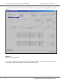
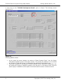
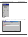
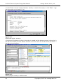
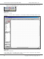
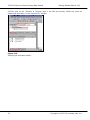
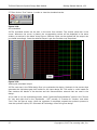
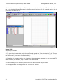
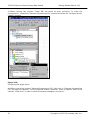
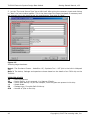
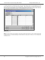
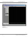
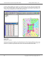
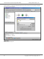
15. From the “Categories” tab in left side of the window, select “buffer” and select the desired
symbol from the “Symbols” tab and place in the editor window, as shown in the figure. The editor
can be zoomed in / out as per the requirement. Notice the grid positions as guides to drawing a
neat layout.
Figure 3-16
Placing the components.
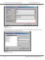
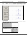
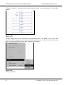
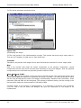
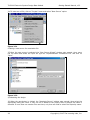
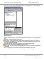
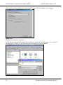
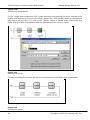
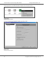
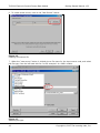
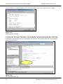
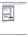
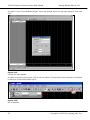
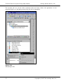
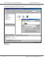
16. After placing the components, the wire has to be connected. To connect the wires right click in
the editor, select “Add” select “Wire”.
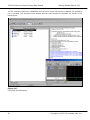
Figure 3-17
Adding wires to the components.
21
Copyright © 2007 The Learning Labs, Inc.