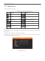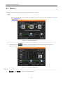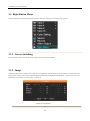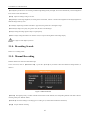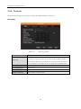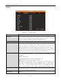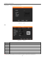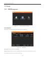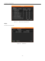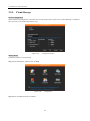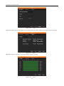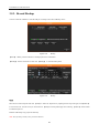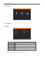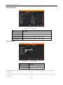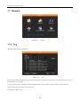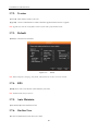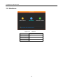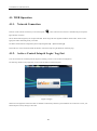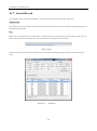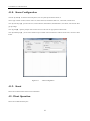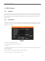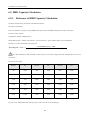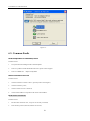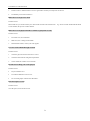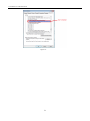
1
Cube DVR User Manual User Manual of Cube DVR Series Precautions Please observe the following precautions, in order to avoid damaging or losing data caused by improper operation. DVR should work at proper temperature and humidity. Do not install DVR in humid, dusty or smoky environment. Require a solid mounting surface for installation. Do not block any ventilation openings. Install under the manufacturer's instructions. Do not spill liquid of any kind on device. Do not put any other equipment on device. Do not dismantle the device. Select specified HDD by manufacture. 1 User Manual of Cube DVR Series Note This user manual is for reference only, subject to available products. This user manual may contain inaccurate data or printing error. Updates to the manual or products themselves will occur without further notification. The products and manual will be updated regularly without further notice Pictures are not from the same machine, for illustrative purposes only. Contact the customer service department if you have any question or want the latest software and file. 2 User Manual of Cube DVR Series Content Chapter 1 1.1. 1.2. 1.3. 1.4. 1.5. 1.6. 1.7. Chapter 2 2.1. Chapter 3 3.1. 3.2. 3.3. 3.4. 3.5. 3.6. 3.7. 3.8. Product introduction ................................................................................................................ 4 Summary ..................................................................................................................................... 5 Features....................................................................................................................................... 5 Installation .................................................................................................................................. 6 Mouse ......................................................................................................................................... 7 Put Method ................................................................................................................................. 8 Power ON/OFF ........................................................................................................................... 9 Icon ........................................................................................................................................... 10 Getting Started ........................................................................................................................ 12 Wizard ...................................................................................................................................... 13 Operation guide ...................................................................................................................... 14 Right Button Menu ................................................................................................................... 15 Main Menu Introduction ........................................................................................................... 18 Search ....................................................................................................................................... 19 Configuration ............................................................................................................................ 21 Storage ...................................................................................................................................... 33 Output ....................................................................................................................................... 43 Maintain .................................................................................................................................... 45 Shutdown .................................................................................................................................. 47 Chapter 4 4.1. 4.2. Chapter 5 5.1. 5.2. 5.3. 5.4. 5.5. 5.6. Chapter 6 6.1. 6.2. 6.3. Web & Client .......................................................................................................................... 48 WEB Operation ........................................................................................................................ 49 Client Operation ....................................................................................................................... 55 Function ................................................................................................................................... 56 DDNS Function ........................................................................................................................ 57 Port Mapping ............................................................................................................................ 59 NTP Function ........................................................................................................................... 61 Voice Intercom ......................................................................................................................... 62 HDD Redundancy..................................................................................................................... 62 HDD S.M.A.R.T ....................................................................................................................... 63 Appendix.................................................................................................................................. 66 TERMS ..................................................................................................................................... 67 HDD Capacity Calculation ....................................................................................................... 68 Common Faults......................................................................................................................... 70 3 User Manual of Cube DVR Series Chapter 1 Product introduction 4 User Manual of Cube DVR Series 1.1. Summary Our Embedded Digital Video Recorder is an excellent digital surveillance product which adopts H.264 video compression, hard disk recording, TCP/IP transmission, and a Linux based OS in addition to some of the more advanced technologies in the information technology industry. This enables a more stable, reliable and high picture quality. These products support synchronized video and audio recording, playback, and monitoring. This series also supports network based system control, as well as excellent network streaming capabilities. 1.2. Features Live View CVBS interface, TV, VGA/HDMI synchronous output. Compression H.264 video compression, G.711 audio compression, supports high definition, low bit-rate video coding and storage. Recoding Recording modes include manual, time, alarm, motion detection, etc.; Support SATA HDD and local disk S.M.A.R.T. technology, Support USB backup and internet backup. Playback Playback search by various conditions, local and network playback; support multiple channel simultaneous playback , support fast, slow, rewind and frame mode; support exact time playback. Camera Control and Alarm Remote camera control, Multi-channel alarm input interface for connecting various types alarm equipment; Motion detection alarm, video loss alarm, masking alarm; Multi-channel alarm output, alarm linkage and on-site lighting control. Communication Interface USB 2.0 high speed interface connecting various backup devices; Standard Ethernet interface, work under various networks. Network Protocol Support TCP / IP, UDP, RTP / RTSP, DHCP, PPPoE, DDNS, NTP etc.; support network real-time live view, recording, playback, control; built-in WEB Server, IE browser for direct access. Operation Mode Support the front panel, remote controls, mouse and so on many kinds of operating mode; With simple, intuitive graphical; With simple, intuitive graphical interface. 5 User Manual of Cube DVR Series 1.3. Installation 1.3.1. Check DVR and Accessories Please carefully check the contents as packing list. If any of the items are missing, please contact with your dealer. 1.3.2. HDD Installation Preparation Prepare a Cross Screwdriver. Steps Caution Only use HDD specified by the manufacturer. HDD will be formatted automatically during startup, it may cause data loss. Recording duration is decided by HDD capability and DVR parameters (recording setup, encoding setup). 6 User Manual of Cube DVR Series 1.3.3. Wiring Installation Preparing for Installation Camera, displayer, AV cable, cable, mouse, other kind‟s cables. Steps DVR in a horizontal position, connect camera to video input interface in back panel. Connect video output to the displayer. Connect cable to RJ45 interface when access network. Mouse should be USB interface type, front or back panel USB interface both work. Power supply. Caution For an external alarm device or PTZ, please refer to the relevant instructions. DVR power lines should be under all lines connected correctly. 1.4. Mouse In addition to front panel keys and remote control menu, the user can use mouse for menu functions. Insert mouse with USB interface into machine panel. Click Left Button If the user does not log in, password box will pop up first; click the left mouse button to enter the main menu when real-time monitoring. Left click mouse the Options icon enter the menu. Exact Instructions on control Change the state of check box and dynamic detection block. Click the combo box drop-down list will pop up. Double Click Left Button Select and confirm or open, for example, double-click playback video. Under multi-screen double click one channel can make the picture full screen; double-click again to return to the previous multi-screen. Click Right Button Pop-up context menu under monitor screen 7 User Manual of Cube DVR Series Exit without saving under menu interface. Turning Wheel Increase or decrease value when fill digital box Switch combo box options. Flip up and down for list box. Mouse Move Select controls in current coordinates to move. Mouse Drag Select motion detection area. Set up regional coverage area. 1.5. Put Method In the input box, choose numbers, symbols, case in English input. Click left mouse button to select value; ←means backspace, _ means a space. Letter Input Interface Figure1.1 Front Panel Number Input Interface Figure1.2 Number Input Interface 8 User Manual of Cube DVR Series 1.6. Power ON/OFF 1.6.1. Power On DVR installed correctly, switch on with power light is on, DVR will boot up automatically. Different model have different boot up status, please refer to the Front-panel Introduction. DVR will detect the hardware when power on, the process will last 20 seconds more or less. After the detection, DVR make a “Buzzing” sound and enter into a multi-screen live view, user can operate now. Please refer to XXX. Main Menu Introduction and Other Introduction. If recording time contains power up time, DVR will automatically start timing recording when power on. Figure1.3 Diagram Note: Power supply has to match with DVR, any other substitutes are not allowed. 1.6.2. Power OFF Hold down on-off key to turn off device. 【Main Menu】→【Power off】→【Power off】. 9 User Manual of Cube DVR Series Figure1.4 Shutdown Note: turn off device and switch off power when changing HDD. 1.6.3. Outage Recovery Reboot after an outage or forceful shutdown, DVR will save the record before outage and return to normal operation mode. 1.7. Icon 1.7.1. Status Icons Description of the status Icon Table 1.1 Description of the Soft Keyboard Icons Icons Description Icons Description Record Channel lock Video loss Adjust the local audio output Allows screen to switch Motion detection polling 10 User Manual of Cube DVR Series 1.7.2. Operation Icon Description of the operation Icon as below Table 1.2 Description of the Soft Keyboard Icons Icons Description Icons Not Selected; Description Save parameters Restore factory settings, return to the last set Selected of parameters after the modified parameters Down Menu Apply current set to the system Confirm revise/get into menu Copy current set to other channels Cancel revise /cancel get into menu Enter the configuration menu Config alarm, video detection trigger‟s Set parameters processing Live View Power on DVR and entry into live view mode: there are date, time, channel names icons which indicate recording and alarm status display on screen. Switch display screens by the front panel, remote control or mouse control. When enable the screen message for external alarm, video loss, masking, motion detection, network and IP conflict alarm, the below interface would popup when those alarm occur. Shows as: Figure1.5 Alarm Status 11 User Manual of Cube DVR Series Chapter 2 Getting Started 12 User Manual of Cube DVR Series 2.1. Wizard By default, the Setup Wizard starts once the device has loaded, as shown in Figure 2.1. Steps: 1. Help: Laview app QR code and cloud server address are list as below. For more information please visit www.laviewcloud.com . Figure 2. 1 Start Wizard Interface 2. After the step 1, click which takes you to the Network Start Wizard window, as shown in Figure 2.2. Make sure you network settings correct and can connect to cloud server Figure 2. 2 Network Configuration Figure 5.1 3. and Click to complete the start wizard settings. 13 User Manual of Cube DVR Series Chapter 3 Operation guide 14 User Manual of Cube DVR Series 3.1. Right Button Menu Click the right mouse button after booting into the real-time browser interface, action menu pop-up, shows as Figure 3.1 Right Button Menu 3.1.1. Screen Switching Max 16 channel in one screen, user can choose single, four, nine and sixteen channel. 3.1.3. Image Adjust the specified screen (single screen) image color hue, brightness, contrast, saturation, gain and white-level parameters set two time periods according to the local environment difference between day and night for each adjustment automatically switch to the best video quality . As shown in. Figure 3.2 Color Setting 15 period set, the device will User Manual of Cube DVR Series 【Period】 two periods can be set according to ambient light during the day and night; device will automatically switch configuration time. Need to select the Enable box. 【Hue】 Adjust according to image color cast 【Brightness】 Visual image brightness, according to the environment, reduces or increases the brightness of the image brightness to make the image relatively clear. 【Contrast】 Adjust image of black and white in proportion, the greater ratio, the brighter image. 【Saturation】 Image color purity, the greater value, the more colorful images. 【Gain】 Enlarge the image signal to improve signal quality. 【White Level】 Change the white level reference value, to improve the brightness of the image display. Note: Different mode different function 3.1.4. Recording Search Refer to 4.3 recording search. 3.1.5. Manual Recording Remark: manual user must have "RECORD" right In live view screen, click on 【Manual Record】, or press the 【video】 key on remote control into manual recording interface, as shown in. Figure 3.3 Manual Record 【Manual】 The highest priority, no matter what the current status of each channel, the corresponding channels will make common recording when press "Manual" button; 【Schedule】 Record according to recording type in recoding set. (Common motion Detection and alarm); 【Stop】 Stop all channel recording. 16 User Manual of Cube DVR Series To change record status of one channel, firstly check the recording status of the channel is selected non-selected (non-selected indicates that the channel is not recording; selected indicates the channel in recording mode).Then use mouse to click, or use【←】or 【→】arrow keys move the active box to the channel, then use 【↑】or【↓】arrow keys or corresponding number key to switch the channel recording status. Note: All selected can change record status for all channels/ 3.1.6. Alarm Output Refer to chapter 4.6.2 alarm output. 3.1.7. Main Menu Click the 【Main Menu】, input user name and password, click【OK】to enter the system menu. As shown in. Figure 3.4 System Login Table 3.1 Default Users User Type User Name Password Administrator Admin 123456 User User 123456 Hidden Default Default Note: Password security: occur alarm after three time’s wrong input and system lockout in 30 minutes after 5 unsuccessful login. For security consideration, please modify the default password. For information on how to add groups, users and modify users information, please refer chapter 4.4.5 Uses Management, Click to toggle the character input method in mouse mode. 17 User Manual of Cube DVR Series 3.2. Main Menu Introduction The main menu as shown, there are search, configuration, storage, output, maintain and shutdown. Figure 3.5 Main Menu 【Search】 Search recoding by type, channel, time and playback. 【Configuration】 recording, motion detection, abnormal, alarm, system, network and user management configurations. 【Storage】 HDD management and backup management. 【Output】 PTZ, alarm output, serial and output mode configuration. 【Maintain】 to display the system log information, version information, stream statistics, and online user and set the factory default, automatic maintenance. 【Shutdown】 Log off the user menu, turn off the machine, restart the system, and switch user and other operations. 18 User Manual of Cube DVR Series 3.3. Search In real-time monitoring screen, click the right mouse button, click 【search】, or enter video playback via main menu interface, as shown in. Figure 3.6 Search Figure 3.7 Search 19 User Manual of Cube DVR Series Table 3.2 Description of Search Index Name 1 Record 2 Calendar Select record search day 3 Channel Choose searched channel 4 Play 5 Recoding mode 6 Time bar 7 Syn 8 Status 9 List Choose the start time, channel, and click “search” will display results in the list. 10 Time Select record search start and end time. 11 Channel No. 12 Record List 13 Record information Description Record and Picture to choice. Playback control: stop/play, pause, fast, slow, previous/next frame in pause. Choose searched recording mode, including whole, outside alarm, motive detection, whole alarm recording. Green means Regular record; Red means alarm record; Yellow means MD record. Implement each video playback channel in the process of playback time synchronization and consistency of the operation. Display status information of function buttons, including fast forward, slow speed, etc. Choose searched channel 128 video records shows in searching list choose file and press enter or double click mouse to view record. Show single record file‟s start and end time, the size of the record file. Tick “ 14 “to choose backup file in file list box, click backup button cancel backup file ---click Backup “√”from backup menu “√”. Table 3.3 Description of Playback Control Icon Key Description Remark Under playback mode, pressing this key, you can get a Video playback : variety of fast cycle switching speeds; fast-forward Fast-forward button button can be used as slow-release button reverse switch key. Under playback mode, pressing this key, switch Video playback : cyclically support a variety of slow-release rate, slow Slow key release button can be used as fast-forward button reverse Actual play rate based on version switch key. ►/ Play/pause Video playback : Slow key Play/pause switch when slow-play To play backwards and single Single left click backward key click again to stop back run under common playback Rewind or Manual single frame single frame playback by clicking playback common playback pause │and│ when single-frame playback, press the play button ►/ to enter the normal playback . Remark: 1. The player playback control bar show file playback speed, channel, time, playback progress and other information. 2. Playback speed and rewind function are related to DVR version, and please prompt on the player panel shall prevail. 20 User Manual of Cube DVR Series 3.4. Configuration User can get into configuration through main menu; Function of system , record, network, alarm, account and abnormity as shown in. Figure 3.8 Configuration 3.4.1. System Figure 3.9 System Configuration Item 【Time】 Description Set the current time. 【Date Format】 To modify the date display format 【Snapshot Interval】 When caught in figure set, scratching figure mode to timing diagram, timing images crawl down at a 【Daylight Saving Time Click “DST” to enable the function, and enter the local DST starting and ending time 【Date Separator】 (DST) 】 【Time Format】 To select the separator for date certain frequency can be uploaded to the FTP server (above maximum upload the latest four images ) 24 hr or 12 hr display mode. 21 User Manual of Cube DVR Series 【Device Name】 Push function of form a complete set of network configuration, display iphone equipment received alarm 【DVR No.】 information device name Number more than one DVR, click “Ad” button on remote control and input a number to select the corresponding DVR to operate When HDD is full, there are two options: “Overwrite” or “Stop recording”. If you select “Overwrite”, the 【Full HDD】 DVR will overwrite the earliest recorded files and continue recording as all HDD in DVR are full. If you 【Language】 select the “Stop recording” option the DVR will stop recording when it reaches capacity language selections vary by different model 【Pack Duration】 To set time length for each record, default is 60 minutes, the maximum is 120 minutes 【Video Standard】 standard: PAL/NTSC (match camera model) 【Auto Logout】 This ranges from 0-60 minutes. 0 means no setting. DVR will automatically let user quit after standby time‟s vacancy Note: Click to save the time modification. 3.4.2. Record Figure 3.10 Record Item 【Channel】 the channel selection Description 【Compression】 H.264 【Resolution】 main stream options are D1/CIF, frame rate scope is different depending on channel and resolution. Vice stream support D1/CIF. Main stream parameters are selectable. 【FPS】 PAL: 1fps-25fps; NTSC: 1fps-30fps 【Bit Rate Control】 Constant Bit rate or Variable Bit rates. Bit rate can be settled in Constant Bit rate. 【Audio】 image quality in Variable Bit rate, 6 is the best but it is fixed in Constant Bit rate Enable or disable the recording of video and audio per channel 【Snapshot】 Select the main stream/extensional stream audio and video resolution coding on and off. 【Snapshot Mode】 Trigger capture, capture picture when alarming 【Picture Size】 CIF capture 【Picture Quality】 6 levels 【Snapshot Rate】 set highest capture rate for single channel,1s/pc 2s/pc 3s/pc 4s/pc 5s/pc 6s/pc 7s/pc 8s/pc 【More 】 enter 【Configuration】 Configuration】 Note: Resolution and frame rate are vary depending on DVR model. 22 There are 6 levels of User Manual of Cube DVR Series Figure 3.11 More Setting Item 【Channel Name 】 show channel name in screen or not Description 【Date Display】 Display】 show date or not 【Channel Display】 drag channel title, save instantly, after quitting by right button, position of channel title would not vary in 【Time Display】 drag time title, save instantly, after quitting by right button, position of time title would not vary in displayer displayer or monitor, and varied position can be shown recorder and WEB interface or monitor, and varied position can be shown recorder and WEB interface 【Video Cover】 4 zones preview and display protect, privacy zone can adjust area 【Preview】 set masking zone, masking zone shown in the screen when display, no masking zone in web and record 【Monitor】 set masking zone, masking zone shown in the screen when display or record 【Copy】 copy one channel‟s configuration to other record plan Record Plan Figure 3.12 Record Plan 23 User Manual of Cube DVR Series Item 【Channel】 Description To select channel. Green, yellow and red refer to the normal, MD and alarm recording type. Modify it in【Set】 【Snapshot】 Form a complete set of screenshots function use regularly, used in the timing capture function of the corresponding channel number 【Set】 Set plan interface Figure 3.13 Recording Config Item 【Period】 Description recording time, 6 recording time zone can be set every day 【regular】 For normal record 【MD】 For Moving detection 【Alarm】 For alarm record 24 User Manual of Cube DVR Series 3.4.3. Network Set the DVR network parameters in “Network” interface. The default IP address is 192.168.1.88 Base setting Figure 3.14 Base setting interface Item Description Enable the DVR to obtain an IP address automatically. If this is enabled, the DVR 【DHCP】 will reboot and search for a DHCP server, and then assign a dynamic IP address. The dynamic IP address will be displayed in the menu. Enter a static IP address if there is no DHCP service available. If you are using the advanced feature PPPoE, 【IP Address】 then the IP/mask/gateway DHCP IP, are and unable be【subnet changed.mask】and【default use()or input numbersand to modify thentoset 【First DNS Server】 gateway】for DNS server IPthis IP 【Alternate DNS Server】 DNS alternate IP 【Physical Address】 physical address of current net port 25 User Manual of Cube DVR Series Advanced Figure 3.15 Advance interface Item Description 【PPPOE】 enable PPPOE, Input PPPOE username and password provided by ISP. Operation: Using this feature, the DVR will automatically obtain a public IP address from your ISP. You can then visit the web interface of the DVR by typing this IP into Internet Explorer. 【3G】 【DDNS】 Insert the 3G card, and input use name, password etc enable the DVR to update a DDNS hostname, which run on a fixed IP address web client.Select DDNS type supports various DDNS currently, include CN99 DDNS, NO-IP DDNS, Private DDNS and Dyndns DDNS, Sysdns DDNS with many other compatible and enable the function; input the update server IP, port, DNS, username and password. Once setup, you can then login via the Web client by using this DNS in Internet Explorer.Private DDNS is available for use with a specific DDNS server and client software.Details refer to 6.1 DDNS function 【NTP】 On/off NTP. Network Time Protocol – allows the DVR to sync with SNTP time server automatically. Host IP: input IP of NTP Server Port: This SNTP support TCP only, the unique port is 123. Update cycle: time interval between 1 min and 65535 min. Time zone: London: GMT+0, Berlin: GMT +1, Delhi: GMT +5, Bangkok: GMT +7, Sydney: GMT +10, GMT-9, Cairo: GMT +2, Moscow: GMT +3, New Hong Kong/Peking: GMT +8, Tokyo: GMT +9, Hawaii standard time(HST): GMT-10, Alaska standard time(AKST): Pacific standard time (PST): GMT-8, Mountain standard time(MST): GMT-7, 【IP Filter】 Central standard time(CST): GMT-6, Eastern standard time(EST): GMT-5, Atlantic standard DVR authority management, if you enable the white list, only the DVR in IP list is allowed to time(AST): GMT-4, Brazil: GMT-3, middle Atlantic: GMT-2. connect. This system supports a max of 64 IPs 【Multicast】 Multicast 26 User Manual of Cube DVR Series 【Max Connect】 range: 0-10, 0 indicates that no connections are allowed 【 Network Connection 【Transfer Capability Set】 NUM】 0-32 should be proper. Need Check first then browse real time video on the network, the number of connections depending on network bandwidth, the greater the number, the greater the network load, the impact of video playback smooth 【Speedy online download】 The automatic setting adjusts these settings based on available network resources. 0-8 should be proper. 【 Network Fluency priority or Picture Quality priority or self-adaption according to the setting, the network Transmission QOS】 automatically adjusts the stream. 【Speedy online download】 if enabled, speed is 1.5-2 times to normal speed 【HTTP】 default: 80 【TCP】 default: 8000, variable 【UDP】 default: 8001, variable 【UPnP】 Protocol on the router automatically open port mapping, make sure UPnP feature is enabled on the router 【Multicast】 tick “Multicast” and set a group in “Set”, IP should be limited as follow picture, port no limit 【Email】 Set the sender mailbox SMTP server IP address, port, username, password and sender‟s mailbox, mail SSL Encryption.Email title support Chinese, English and Arabic numerals input, Max input 32 characters. Max support 3 Receive Addresses and SSL Encryption Mailbox. 【FTP】 Tick “FTP” and click “Set Set FTP server IP address, port and destination folder. System will create folders by IP, time and channel if there is no remote folder specified. FTP username and password Set a maximum file size, channel, time, type and etc. Set FTP file length. Upload the whole record if the file length is smaller than setting; leave out the exceed part if the file length is exceed the setting; 0 refers to uploading the entire record in any condition. 【Alarm Center】 Set up to interface two time periods and choose from 3 different record types for channels reserved 【Push】 Push service and premium version of the Iphone client, the operating interface is mainly used to push the opening of the service function, the current mobile client associated with the hard disk video recorder, even in the case of mobile client did not open, a local of real-time alarm message will be sent to the Iphone for customer inquiries. 27 User Manual of Cube DVR Series Network status: Display the current DHCP PPPoE and IP. Figure 3.16 Push P2P Figure 3.17 Network Item [Enable] Description Enable P2P by clicking OPEN, and click OK to finish the device configuration [Transfer Mode] Fluency/Latency/None [Device ID] Each serial number Of devices are different, this cannot be modified [Password] This is generated by the system, you can change it [Local Port]: Default is 3000, can be modified [State] Check the connect status of the device and the server Remark When it shows Offline, click【Ping】 to check the connect status again Note: If the status still shows offline, please check the if the network light is on, and the device is connected or not. 28 User Manual of Cube DVR Series 3.4.4. Alarm Configuration Local alarm Figure 3.18 Local Alarm interface Item 【Alarm Input Channel No.】 Description select the alarm input channel 【Enable】 the specified alarm in /out 【Type】 select the alarm circuit type 【Process Mode】 enter alarm linkage interface Figure 3.19 Item 【Period】 Alarm Period Description set alarm active period 29 User Manual of Cube DVR Series Figure 3.20 Linkage Set 【Linkage】 on/off 【Record Channel】, 【PTZ】, 【Tour】, 【Snapshot】 linkage and select channel. Figure 3.21 Local Alarm Process 【Abnormity】: enable or disable 【Alarm Out】, 【Show Message】, 【Send Email】 and 【Buzzing】 Time delay for alarm cancel is 10-300s Notice: some models have no LOCAL ALARM Function; please refer to the Product Specification. 30 User Manual of Cube DVR Series Video detection Item 【motion detection】 【zone setting】 【Sensibility】 【management】 【preview】 【video lose】 【management】 【preview】 Description motion detection and alarm 22*18 =396 zones mask 6 grades as same as local alarm alarm preview detect video loses and alarm as same as local alarm alarm preview 3.4.5. User Management Note: Group and user names can be from 1-6 characters in length. Valid characters include letter, numbers, and limited symbols: underline, subtraction sign, dot, you may not use a space as a leading or ending character. There is no limit to the number of groups or users. By default there are two different group levels: admin and user. User management determined upon two levels: the group and the user level. Group and user names cannot be duplicated, and each user can only belong to one group. Figure 3.22 User management interface 31 User Manual of Cube DVR Series Item 【Add users】 Description add group member information and set authorities. Default users are: “admin”, “user” and hidden “default”, the password of first two username is 123456. “Admin” has advanced authorities; “user” only has surveillance and playback authority. Hidden default: operate in password-less login mode, cannot delete, DVR login in this name automatically if “no user login” user can revise limits of power then operate some without login. Enter【Add users】input username, password and select group and reusable options. Reusable allows the account to be used by multiple logins. 【Modify users】 【Add group】 Users can only belong to one group. User rights cannot exceed group rights. modify existing group member information and authority add group and set group authorities.Set a group and authorize 60 items including control panel, shut down, live view playback, record, record backup, PTZ control, account, system information, alarm in /out setting, system config, search log, log delete, upgrade, operation authority, etc. 【Modify group】 modify existing group information. 【Modify Password】 change password Select a username input the old password and new password twice. Click【Save】to confirm Password can be in 1-6 numbers, letters or symbol; blank in beginning and end is invalid. The account with management authority could change others‟ password. 3.4.6. Abnormity Figure 3.23 Abnormity interface Item 【No Disk】 Description alarm when HDD is not present or can not be detected 【Disk No Space】 alarm when hard disk capacity is lower than setting 【Network Failure】 alarm when network is not connected. 【IP Conflict】 alarm when IP address conflict 【Disk Error】 alarm when there is error in reading and writing hard disk. 【Process】 includes:【Alarm Output】, 【Display On Screen】 and 【Send Email】 32 User Manual of Cube DVR Series 3.5. Storage 3.5.1. HDD Management Figure 3.24 Maintain and manage local HDD Base Configuration “Base Config” as, shows DVR storage capacity, available space and working status. Figure 3.25 HDD Manage 【Format】it is possible to format an individual HDD. 【Set】to set HDD as read-write, read only or redundancy mode. In read only mode, video data cannot be covered. Note: Hard disk format operation result in the loss of video data 33 User Manual of Cube DVR Series Figure 3.26 HDD S.M.A.R.T intelligent detection Record Record menu, shows start-stop time. Figure 3.27 HDD Record 34 User Manual of Cube DVR Series 3.5.2. Cloud Storage Device Configuration Select channel and configuration your needs, here we take motion detect, Video Loss, Camera Masking as example to show you how to use cloud storage step by step. Figure 3.28 Configuration interface Motion Detect Upload the snapshot on cloud storage Step 1: Enter Main Menu, and then click ALARM Figure 3.29 Configuration Step 2: Enter ALARM, and then click Detect. 35 User Manual of Cube DVR Series Figure 3.30 Alarm Step 3: Enter Detect tab to choose channel, check Motion Detect checkbox, and then click Process button on the right. Figure 3.31 Detect Step 4: Enter Process interface to set period, linkage set, process as below. Figure 3.32 36 Period User Manual of Cube DVR Series Figure 3.33 Linkage Set Figure 3.34 Process Video loss/ Camera masking Upload new and snapshot on cloud storage Follow the step from 1 to 4 as motion detect to finish the configuration. 37 User Manual of Cube DVR Series Connect Drop box Step 1: select Drop box, Click Bind Figure 3.35 Cloud storage Step 2: open the linking via you browser (scan QR code with your Ipad , phone.) Figure 3.36 Bind Drop box Step 3: The linking will lead to the “dropbox” website. And require to login your Account and password. (You must have account of “dropbox”, if you haven‟t, please enter www.dropbox.com to apply for an account) 38 User Manual of Cube DVR Series Figure 3.37 Drop box Sign in Step 4: Authorized the specific DVR to visit your drop box, and get the authorization code. Figure 3.38 Drop box authorization Step 5: Enter the authorization code into your DVR from web pages. And click OK Figure 3.39 Enter authorization code 39 User Manual of Cube DVR Series Figure 3.40 Figure 3.41 Drop box capacity Bind Success Step 6: After finish your DVR trigger motion detection, video loss, Camera masking settings. It will upload the information to your drop box automatically. Then you can login drop box and get the information you want.(www.dropbox.com) Figure 3.42 Login drop box 40 User Manual of Cube DVR Series Figure 3.43 Check information 41 User Manual of Cube DVR Series 3.5.3. Record Backup Connect an External USB device with the USB port to backup in the “Record Backup” menu Figure 3.44 Backup 【Detect】: Identify external USB device and display the device information. 【Backup】: tick the external device and click 【Backup】 to enter the backup menu Figure 3.45 Backup Back Select the record start-stop time and click 【Add】 to add in list; duplicate it by inputting the start-stop time again; click【Delete】 to clear the files list. Tick the record you want and click 【Start】 to backup and display time remaining. 【Delete】 delete all data in USB backup device Remark: USB backup carry player automatically Note: this operation probably cause permanent data loss 42 User Manual of Cube DVR Series 3.6. Output Figure 3.46 Output 3.6.1. Display Display Menu Figure 3.47 GUI Item 【Transparency】 Description total 4 grades 【Channel Name】 to modify channel name, available options are symbols, letters, and numbers 【Time Display】 to choose whether time displays on screen 【Channel Display】 to choose whether channel name displays on screen 【Over Info】 to choose whether overlaying information displays on screen Note: 1) Channel name up to 48 half-width characters 2) 16 characters is suitable, otherwise some problems happen when multi-screen 43 User Manual of Cube DVR Series Output configuration Figure 3.48 Output config Item 【VGA Output】 Description to select VGA resolution and refresh rate, default is 1024×768@60Hz. 【TV Adjust】 to adjust TV output area. Modify the image to the right size for monitor 【VGA/TV Color Set】 to adjust displayer‟s hue, brightness, contrast, saturation 【TV Color Set】 to adjust monitor or TV‟s brightness, contrast, saturation Tour configuration Figure 3.49 Tour configuration Item 【Motion Tour Type】 Description to set the motion detection tour mode 【Alarm Tour Type】 to set the alarm tour mode Setting tour mode and interval between rotation , the time is within 5-120s,the mode include single screen, four-, eight-, nine-, sixteen-screen. Note: Shortcut Setting: click the button at the top right corner of the monitoring picture or press the Shift Key to switch, you can control the tour. 44 User Manual of Cube DVR Series 3.7. Maintain Figure 3.50 Maintain 3.7.1. Log 【LOG】 display system log information. Figure 3.51 Log Select the type and time press the Find, the system will display the log in tabular form, you can also click the backup button to export the log backup to your computer. Log type: system operation; configuration; data management; alarm event; recording; user management; log delete; document operation. Select the type and time to filter the log list. Click “delete” to delete all logs. 45 User Manual of Cube DVR Series 3.7.2. Version 【Version】: Show features, software version etc. 【upgrade】: Connect a USB flash device which contains the upgrade firmware and click “Upgrade”. Note: upgrade may cause the startup failure. Please operate under professional direction. 3.7.3. Default 【default】 restore(items are selectable) Figure 3.52 Default Note: Menu transparency, language, time format, video format, IP, user ID, etc are not restored. 3.7.4. BPS 【BPS】shows video‟s size, data rate of each channel by wave form. Note: Estimated value just for reference 3.7.5. Auto Maintain 【Auto Maintain】set auto maintenance items. 3.7.6. On-line User 【On-line Users】check the current online user‟s status. 46 User Manual of Cube DVR Series 3.8. Shutdown Figure 3.53 Shutdown Item 【Menu Logout】 Description log out of the current user account 【Shutdown】 shutdown the DVR 【Restart System】 reboot the DVR 47 User Manual of Cube DVR Series Chapter 4 Web & Client 48 User Manual of Cube DVR Series 4.1. WEB Operation 4.1.1. Network Connection H Series: Check network connection by LCD on front panel, “ “ refers connection error, P Series: Check B-Lamp on front panel, light indicates connection Set IP, subnet mask and gateway for computer and DVR. Please assign the same segment IP address without router, need to set the appropriate subnet mask and gateway with router. The detail of DVR network configuration please see【Configuration】→【Network Setting】 Ensure the IP is correct and check whether the DVR is on the network by using the Windows command “ping”. 4.1.2. Active x Control Setup & Login / Log Out User cans remote access to DVR by Internet Explorer, assuming you have a correct network configuration. The following interface wills popup when you access the IP address in Internet Explorer. Figure 4.1 Login Install ActiveX: Right click and choose install. If installation is blocked by Windows, please add the IP as a trusted site or lower your Internet Explorer security settings to allow this. 49 User Manual of Cube DVR Series Figure 4.2 Install The following interface will popup when you input your username, password and click “Login”. Interface like Diagram 4-3 Web Interface when user login successfully. Click “Exit” to quit. Figure 4.3 Login If the Win 7 system prompts control is not registered, click Close button in the above page, and click close the Active X filtering, and then click Install button in the bottom of the page. It needs resetting if you can login the interface, but camera 01 and the other 15 channels are hidden. Click 【Tool】-【Compatibility View Setting】-【Check】(display all outlets (E) in compatibility View), then click Close to finish it. 4.1.3. WEB Operation Interface Table 4.1 Web operation Interface Index Name Description 1 Channel Channel selection 2 Function 3 Surveillance window 4 Image color & other saturation 5 PTZ control PTZ Control Menu 6 Menu System config, record search, alarm setting, exit, etc. Local playback: playback local record Open all: play live views in surveillance window Change window layout Image color: modify brightness, contrast and saturation Other: set capture path, record download path and reboot 50 User Manual of Cube DVR Series 4.1.4. Live View Into the WEB interface, select the focus window in live window, the focus window has a light blue border. From the left channel column select channel Figure 4.4 Live View Click on 2 area in upper right corner can choose open / close the channel of the main stream or secondary stream, shows the current DVR's IP and rate information, as shown in. Figure 4.5 Web Menu toolbar Lower left corner shows the current video channel name. Upper right corner shows the current video time information. Click “ “(Lower left corner of the display window)to switch between single screen and multi-screen. Lower right corner of the display window is function keys, as, refer to area zoom, Multi-screen switch, local record, capture and mute/unmute audio. Area zoom: Video images can be enlarged; Multi-screen switch: switch from single screen to multi-screen and vice versa; Local record: save and record video to a local HDD while in a live view. Set recording path in configuration; Capture: capture of the present channel, set the path in “other”; Sound: on/off sound. Off video: off the focus window video. 51 User Manual of Cube DVR Series Figure 4.6 Function Key 4.1.5. PTZ CONTROL Set protocol(see【Setting】→【PTZ Config】) Control PTZ direction, step size, zoom, IRIS, preset, tour, pattern, border scan, light, wiper, auto pan, etc. Step size controls PTZ direction and speed, e.g. step size 8 is moved faster than step size 1. Eight direction rotations: up, down, right, left, upleft, upright, lower left, lower right. Figure 4.7 PTZ config Border scan Operation: select the camera line scan of the left/right margin by direction button, and click the Settings button in the left /right margin position to determine the left border. 52 User Manual of Cube DVR Series Preset Operation: modify preset position by direction button and inputting a preset number, then click “Add” to save. Tour Operation: select “Tour”; Point between the first cruise line cruise input box value. And input numbers in “Path” and “preset”. Click 【Add Preset】to adds one preset in the cruise path, and repeat to add additional presets. Click 【Clear Preset】to delete a preset, repeat to delete more. Pattern Operation: Click “Pattern” in order to record an automated pattern. Then, go back to the PTZ controls in order to modify the zoom, focus and IRIS, etc. Stop recording in “Pattern” setting to save the pattern. AUX On/off one of AUX Wiper On/off wiper under protocol 4.1.6. CONFIGURATION Access DVR local configuration menu by click “System Setting”, the further details please refer【Local operation guide】. Figure 4.8 Configuration 53 User Manual of Cube DVR Series 4.1.7. Search Record Click “Search record” to open the search interface , can search and operate record, alarm, motion, local record Search record By selecting the record type, start and end times, and click the check button, get a list of files on the DVR. Select the appropriate file and download can be played Play Double click a search result to play in video window. Control the playing video by the control keys on the bottom. At this point, the bottom of the video window will display the video control buttons, video playback can be controlled. Figure 4.9 Play Download: select a searched video to download to local. The download speed and percentage are displayed on the bottom of the screen. Figure 4.10 Download 54 User Manual of Cube DVR Series 4.1.8. Alarm Configuration Click the 【Alarm】 to enter the alarm setup menu, user set up and operate the alarm mode, as. Choose type of alarm on menu, monitor video loss, motion detection, and disk full, disk error, video mask, external alarm. Click 【Video Pop-up】, open the video loss, motion detection, hard disk full, hard disk failure, video block, video encoder alarm pop-up linkage. Click 【prompt】, open the prompts: when an alarm occurs in real-time will pop-up alarm window menu. Click 【Sound Pop-up】, you can choose alarm tone pre-recorded on the local hard drive when an alarm occurs, tone file in WAV format. Figure 4.11 Alarm configuration 4.1.9. About Please refer to WEB controls related version information. 4.2. Client Operation Please refer to IMS 200 Description 55 User Manual of Cube DVR Series Chapter 5 Function 56 User Manual of Cube DVR Series 5.1. DDNS Function 5.1.1. Summary Dynamic DNS is a kind of system which point internet domain name to variable IP. According to the rule of internet domain name, domain name must associate with the fixed IP address. Dynamic DNS provide a fixed Name server for the dynamic domain, and then guide the domain search to the IP address of dynamic user through Name server, which can make the outside user connect to the dynamic user‟s URL. 5.1.2. FNT DDNS FNT DDNS is a professional dynamic domain name analysis server embedded in our company‟s DVR.Can be directly on the device to register above, specific steps are as follows:【MAIN MENU】->【CONFIGURATION】->【NETWORK】->【Advanced】-> 【DDNS】,choice FNT DDNS. Figure 5.1 1. DDNSType choice FNT DDNS, and Enable. 2. Type usename, and Domain Name=use name+.faceaip.net. 3. Type Password. 4. Click 【Register】, if the domain name has not been registered, will pop up registration, if the domain name being used, you will be prompted to register failure. Best advice: amend the basic configuration of DNS server to the router's DNS servers. 5. After successful registration, click 【OK】,complete preservation. 57 User Manual of Cube DVR Series 5.1.3. NO-IP(www.no-ip.com) Register Register new username at no-ip, click 【Create Account】. Create domain name, click 【Add a Host】. Embedded DVR Setting Open 【Main Menu】→【Management】→【Network】→【Advanced】→【DDNS】→【Enable】 Table 5.1 Explain: Name Configuration DDNS Type NO-IP DDNS Server IP dynupdate.no-ip.com Port 80 Domain Name xxx.xxx.org User Name xxx Password xxxxxx 5.1.4. DYNDNS DDNS(www.dyndns.com) Register To login at dyndns, register an account. Click on the confirmation link, login the account, click 【Add Host Services】 at [My Services], set your own realm name, and then operate according to the procedure. Configuration of the Embedded DVR Open 【Main Menu】→【Management】→【Network】→【Advanced】→【DDNS】→【Enable】 Table 5.2 Explain: Name Configuration DDNS Type Dyndns DDNS Server IP Members.dyndns.org Port 80 Domain Name xxx.xxx.com User Name xxx Password xxxxxx 58 User Manual of Cube DVR Series 5.1.5. Test and Verify DDNS After setting the Embedded DVR, wait for a few minutes, analysis records will update. Click Operation in the Menu of computer, input “cmd”, click “OK” to open a window. As the shows. Figure 5.2 Input “ping+ Domain name” then presses Enter, as the shows. Figure 5.3 The computer will analyses the domain name confabulated in DVR, and return to the current IP, as the picture shows underlined in red. When the IP correspond to the embedded DVR‟s IP in Public internet, it means the DDNS is setting right. If they are not, please check the network connection of embedded DVR and DDNS information. 5.2. Port Mapping Port mapping is mapping a port of outside web host‟s IP address to a machine inside web, and provide the service. When user connects to the port of the IP, the server will automatically map the request to the corresponding machine inside LAN. 59 User Manual of Cube DVR Series With the function of port mapping, we can map many ports of a machine‟s IP address to different machines‟ different ports inside web. The port mapping can also have other special agent functions, like POP, SMTP, TELNET, etc. Theoretically, it can provide more than sixty thousand ports. For example, if we want to map a web server which has an IP address of 192.168.111.10, we just need to input the IP address and TCP port 80 into the port mapping chart of the router. There are two ways to map the port: UPnP function automatically map and modify the router‟s port mapping chart by manual. 5.2.1. UPnP FUNCTION In order to get connection to the Embedded DVR through Public network, we need to set the Router to cross the NAT of Embedded DVR. UPnP can make the NAT cross automatically by the UPnP agreement of Embedded DVR, and don‟t have to set the Router. Note: to realize the UPnP Function, there must be Router support and enable the UPnP Function. The first step Connect the Router to the network, get to the Menu of the Router, set the Router, and enable the UPnP Function. Routers made by different manufacturers may have some difference, please refer to the specification carefully before setting the Router. The second step Connect the Embedded DVR to the Router; the configuration will automatically gain the IP address or static IP. After setting up the IP, click the Advanced Config. And get to the XXX, ports and multicast etc. choose to open the Enable at the 【UPnP port mapping】 The third step Enter into the Router management interface; detect the port if there is already a Port mapping. If there is, it shows UPnP setting‟s finished. The forth step Input the IP address in IE, and add port number of the Embedded DVR, for example: 155.157.12.227:81. If you want to enter by the Client Software, use the TCP port offered by the outer net. Note: if there are a few embedded DVRs need to set the UPnP function, in order to avoid IP conflict, set the ports of embedded DVR into different ports numbers. Otherwise, it will choose the embedded DVR port set preceded as the first choice. 60 User Manual of Cube DVR Series 5.2.2. MAMUAL PORT MAPPING The first step Connect the Embedded DVR to the Router, set the static IP. The second step Log in Router, enter into the configuration menu of Router, and set the menu. Then get to port, set the IP distributed by the Embedded DVR, and set the rule of port mapping, add HTTP and TCP port into mapping list. Default access ports of Embedded DVR include HTTP port 80 and TCP port 8000, if the ports are occupied by the other devices, please modify the default port of the Embedded DVR into other vacant ports. The third step Input the public net IP address in the IE, and add the port number of the Embedded DVR you want to access after the IP, for example: http://155.157.12.227:81. If you want to access by Client Software, you can use the outer net TCP port directly. Notice: for detail configuration setting, please refer to the user manual of Router. 5.3. NTP Function Enable NTP function; make the time synchronization with both the DVR and GPS clock server, to ensure the accuracy of device time. 5.3.1. Internet Configuration Get to the 【CONFIGURATION】→【NETWORK】, choose 【Advanced】, and then choose 【NTP】to set. After the device can access the Internet, NTP server can use the standard NTP server as the time. For example, the server of China‟s national research center (IP address: 210.72.145.44). Input the IP address and domain name of relative server at NTP setting. To activate NTP, click to choose “Enable”. The interval of changing time is from 1 to 65535 minutes. 5.3.2. Internet Configuration If DVR work under the intranet, user can set up a privately-owned server as clock source.NTP address in DVR configuration fill in privately-owned NTP address can work. Privately-owned NTP server can adopt standard NTP products and accurate time PC system. Please refer to below instruction when adopt PC system as a NTP server. 61 User Manual of Cube DVR Series NTP Server Set Up under Windows “Start” menu → “Run” (or Win+R), input “regedit” to get into REGEDIT. Build a new key assignment of WORD Value under: HKEY_LOCAL_MACHINE\SYSTEM\CurrentControlSet\Services\W32Time\Parameters registry sub key; Change the value to 1, and save. Restart the computer. NTP server set up under Linux system Due to the particularity of Linux system, for detail way to erect the NTP server, please refer to every editions of the manual. 5.4. Voice Intercom 5.4.1. Summarize Embedded DVR Bidirectional Talk: user can talk to remote client software or Web via DVR audio input and output ports; user can listen voice from Client Software and WEB via DVR audio output ports. Two types of bidirectional talk ---- sharing and standalone ----for different models, exact info please refer to specifications. 5.4.2. Configuration Local configuration Connect a microphone to the MIC input port, connect loudspeaker to the audio output port. If no standalone MIC input port, please connect microphone to the number 1 audio input port. Note: local output needs active audio output device. Remote PC Configuration Connect microphone and loudspeaker to computer. USE Enable bidirectional talk in IMS software or WEB. 5.5. HDD Redundancy HDD redundancy function can backup the recording file, user can retrieve files by HDD redundancy if single HDD damaged, by which improve the system‟s safety. 62 User Manual of Cube DVR Series Hard disk redundancy function is through the designated channel data double backup in HDD, so DVR need a standalone HDD for redundancy function. HDD redundancy configuration Open main menu enter into the storage configuration, choose one HDD as the redundancy HDD, click setting. Redundancy HDD must be an independent HDD, user can set several HDDs as a redundancy HDD group. Once a HDD is assigned as redundancy HDD, the recording data can be saved in both normal HDD and redundancy HDD. Data on redundancy HDD should be automatically cycle coverage, cycle period depends on the recording data and redundant HDD‟s capacity. Note: Make sure 2pcs HDD at least in DVR, one for read and write, another for redundancy. Channel redundancy configuration User can choose part channels or all channels to set redundancy backup. Please get to 【Configuration】→【Record】, choose redundancy channel, check mark 【Redundancy】. Note: the data in channel turn off redundancy only is recorded in normal reading and writing HDD if the redundancy is not enabled. Retrieve HDD redundancy User can retrieve backup recording data from redundancy HDD when RW HDD damage or data lost. Firstly, shut down DVR and remove damaged HDD, then restart DVR; Secondly, Get into 【Main menu】→【Storage】, set redundancy HDD as a reading and writing HDD, and then it can be searched. 5.6. HDD S.M.A.R.T S.M.A.R.T: “Self-Monitoring, Analysis and Reporting Technology” S.M.A.R.T HDD can analysis head, disc, motor, circuit operation, history and default security values via monitor instruction in HDD and surveillance software in host. Alarm will be sent to user automatically when the value is outside the scope of the security situation. Detection parameters of Seagate HDD for example are divided into seven: ID detection code, Attribute Description, Threshold, Attribute Value, Worst, Date, and Status. 1 ID detection code ID detection code is not the only; manufacturer can use different ID code or increase or decrease its quantity according to the detected parameter‟s quantity. For example: the ID detection code of WEASTERN Digital‟s product is “04”, parameter is Start/Stop Count, but the parameter of same code in Fujitsu‟s product is “Number of times the spindle motor is activated”. 2 Attribute Descriptions 63 User Manual of Cube DVR Series Attribute Description: name of detection item. Manufacturer can increase or decrease. As ATA standard update constantly, sometimes different models in same brand maybe different ,but must ensure major test items specified in S.M.A.R.T .(although different manufacturers have specific naming convention ,the essence of monitoring is the same.) 1 Read Error Rate 2 Spin up Time 4 Start/Stop Count 5 Relocated Sector Count 7 Seek Error Rate 9 Power-on Hours Count 10 Spin up Retry Count 194 Power temperatures 195 ECC on the Fly count 197 Current Pending Sector Count 198 Disconnection beyond repair 199 CRC cyclic redundancy check 200 Write Error Count Note: Different manufacturers and different models have different attribute description, user has no need to know exact meaning, attribute detection values enough for them. 3 Thresholds It is specified by manufacturer calculated through a specific formula. If there is a attribute value lower than the threshold, which means HDD become unreliable and data stored is very easy to lose. Composition and size of reliable attribute values is different for different HDD. It should be noted that, ATA standard only provides some SMART parameters; it does not provide a specific value. "Threshold" value is determined by manufacturers based on products‟ features. Thus, results tested by manufacturer provided detection software is very different from testing software under Windows (such as AIDA32) 4 Attribute Value Attribute value is the maximum normal value; the general range is from 1 to 253. Typically, the maximum attribute value is 100 (for IBM, Quantum, and Fujitsu) or 253 (for Samsung). Of course, there are some exceptions, for example, some models produced by Western Digital have two different attribute values, and property value is set 200 when initial production, but after then it is changed into 100. 5 Worst Worst value is the largest non-normal value in HDD‟s running. It is a value calculates for HDD‟s cumulative running, it is constantly refreshed according to running cycle, and very closed to the threshold. Whether the HDD is normal by S.M.A.R.T analysis is based on the comparison with threshold. The maximum value appear when new HDD start to use, which would continue to decrease with 64 User Manual of Cube DVR Series the everyday use or error happen. Consequently, larger attribute values mean better quality and higher reliability; smaller values mean more possibility of failure increases. 6 Dates Actual values of HDD‟s detection items, many items are cumulative values. 7 Statuses It is current statues of HDD‟s every attribute after analyzing and comparing above attribute values by S.M.A.R.T, also is important information to judge HDD healthy or not. There are three statuses: Normal, Alarm and Error----which is closely related with Pre-failure/advisory BIT. 65 User Manual of Cube DVR Series Chapter 6 Appendix 66 User Manual of Cube DVR Series 6.1. TERMS Dual-stream Dual-stream: one high bit rate stream for the local HD store, QCIF/CIF/2CIF/DCIF/4CIF coding, other low bit rate stream for network transmission, such as QCIF / CIF coding, I Frame I frame: intra frame image, remove redundant information to compress the transmittal data, also called key frames. B Frame B frame: According to time redundant of the source image sequence previously encoded frame and account the source image after the encoded frame to compress transmittal data, also known as bi-directional prediction frame. P Frame P-frame: according to image frame lower than the previous „time redundant to compress transmittal data, also called predicted frames. Wide Dynamic Bright parts and dark parts in particular can be seen very clearly at the same time. Wide dynamic range is a ratio between the brightest luminance signal value and the darkest value. S.M.A.R.T SMART (Self Monitoring, Analysis and Reporting Technology): now widely used in hard disk data security technology, monitoring system analysis Motor, circuit, HDD and disk head when HDD working, warn when abnormality, sometimes will automatically slow down and back up data. CVBS Composite Video Broadcast Signal, consists of luminance and color signal from the composite baseband signal. BNC Coaxial cable connector, composite video signals or audio signals, commonly use 75 ohm connectors. BNC welding and should pay attention to weld strength and remove burrs, or the signal wire and shield‟s contact will lead to a substantial attenuation of signal strength. 67 User Manual of Cube DVR Series 6.2. HDD Capacity Calculation 6.2.1. Reference of HDD Capacity Calculation The first time install DVR, please check if the HDD has installed. The capacity of the HDD There is no limitation of capacity of single HDD to DVR, please choose the HDD according to the Vedios‟ saving time. The choose of the Capacity Computational formula of HDD Capacity: Whole HDD Capacity = number of the channels × time in need (hour) × spent of HDD Capacity per hour (MB/hour) Similarly we can have the formula of recording time: Recording time(hour) TotalHDDCa pacity(MB) CapacityOccupationperHour (MB/ hr) AmountofCh annel Note: 1GB=1000MB, not 1GiB=1024MiB, so HDD capacity shown in Base Configuration under HDD Management less than real marked. File size per hour (CBR). Bit Rate File Bit Rate File Bit Rate File 96k 42M 320k 140M 896k 393M 128k 56M 384k 168M 1.00M 450M 160k 70M 448k 196M 1.25M 562M 192k 84M 512k 225M 1.50M 675M 224k 98M 640k 281M 1.75M 787M 256k 112M 768k 337M 2.00M 900M Table 6.1 File size is more unpredictable when VBR style, please refer to the real size of recording file. 68 User Manual of Cube DVR Series 6.2.2. Hard Disk Problem Use Detection Tool provided by the HDD manufacturer to detect the Function of HDD to solve data problem. We recommend Seagate and Western Digital. How to detect Seagate HDD a) Get into www.seagate.com, Click Support & Downloads choose Sea Tools, download tool, as Figure 6.1 b) Double-click to install downloaded file , click installed file to detect the HDD information on PC. c) Choose the HDD for detection (other manufacturer‟s hard disk suitable too). How to detect WDC HDD a) Get into www.wdc.com , choose WD support / download / SATA&SAS / WD Caviar / GP, download software as Figure 6.2 b) Click Icon to hard disk detection after downloading . c) Double click hard desk in device list, as: 69 User Manual of Cube DVR Series Figure 6.3 6.3. Common Faults DVR startup failure or continuously reboot Possible reasons: 1. The system has been damaged from a bad DVR update. 2. There is a problem with the DVR main board error, please contact supplier. 3. There is an HDD error. Replace faulty HDD. Remote control does not work Possible reasons: 1. Check for batteries in remote control , especially Positive and Negative; 2. Check for batteries‟ power; 3. Check if remote receiver is obscured; 4. Check if DVR address corresponds to the remote control address. DVR cannot control PTZ Possible reasons: 1. RS-485 cable connection error, A, B ports are inversely connected; 2. PTZ decoder, protocol, baud rate, address are incorrect; 70 User Manual of Cube DVR Series 3. Parallel connect a 120Ω resistance to resolve signal reflex caused by too many PTZs on the line. 4. The RS-485 port on DVR is defective Blurred screen in preview mode Possible reasons: Please make sure your cameras match your video format selected in the General menu. E.g. camera is NTSC standard but the DVR is PAL standard, the preview would be blurred. Blurred screen in playback mode or failure to playback records Possible reasons: 1. Procedure error, reboot the DVR 2. HDD error, test or change out the HDD 3. DVR hardware failure, contact your local supplier Can not connect DVR through network Possible reasons: 1. Check the physical network connection is correct. 2. Check the DVR network configuration parameters. 3. Check whether IP conflicts exist in network. Download recording can not be played Possible reasons: • Player installation error. • The USB or HDD device has an error. • Do not install graphic software later than DX8.1. Internet Explore Crash Possible reasons: Close IE explore, enter into the tool bar. 71 User Manual of Cube DVR Series Figure 6.4 72