1
MGW CMAP 8010
GSS Maintenance
Installation &
Operation
November 2003
S/N 213672
Error! No text of specified style in document.
Maintenance
ii
CMAP 8010 - GSS
Legal Rights
Legal Rights
© 2003 by Alvarion Ltd. All rights reserved.
No part of this publication may be reproduced in any material form
without the written permission of the copyright owner.
Trade Names
Alvarion®, eMGW®, MGW®, BreezeACCESS®, BreezeCOM®,
BreezeLINK®, BreezePHONE®, BreezeNET®, WALKair®, WALKnet®,
Alvari™, AlvariX™, AlvariSTAR™, AlvariBASE™, BreezeGATE™,
BreezeIP™, BreezeLAN™, BreezeWEB™, BrezEXCHANGE™,
BreezeCONFIG™, BreezeWIZARD™, BreezeSECURE™, BreezeVIEW™,
BreezeMANAGE™, BreezeACCESS II™, BreezeACCESS II CX™,
BreezeACCESS XL™, BreezeACCESS MMDS™, BreezeACCESS
OFDM™, BreezeACCESS LB™, BreezeACCESS TM™, BreezeACCESS
VL™, BreezeACCESS V™, BreezeACCESS GO™, WALKair 1000™,
WALKair 3000™, BreezeNET Pro.11™, BreezeNET, DS.11™, BreezeNET
DS.11b™, BreezeNET DS.5800™ are trade names or trademarks of
Alvarion Ltd. Other brand and product names are trade names or
trademarks of their respective owners.
Statement of Conditions
The information contained in this manual is subject to change without
notice. Alvarion Ltd. shall not be liable for errors contained herein or for
incidental or consequential damages in connection with the furnishing,
performance, or use of this manual or equipment supplied with it.
Warranties and Disclaimers
All Alvarion Ltd. (“Alvarion”) products purchased from Alvarion or
through any of Alvarion’s authorized resellers are subject to the
following warranty and product liability terms and conditions.
Exclusive Warranty
Alvarion warrants that the Product hardware it supplies and the
tangible media on which any software is installed, under normal use
and conditions, will be free from significant defects in materials and
workmanship for a period of fourteen (14) months from the date of
shipment of a given Product to Purchaser (the “Warranty Period”).
Alvarion will, at its sole option and as Purchaser’s sole remedy, repair or
replace any defective Product in accordance with Alvarion’ standard
RMA procedure.
Revision 1.0
i
Legal Rights
Disclaimer
(a) UNITS OF PRODUCT (INCLUDING ALL THE SOFTWARE)
DELIVERED TO PURCHASER HEREUNDER ARE NOT FAULT
TOLERANT AND ARE NOT DESIGNED, MANUFACTURED OR
INTENDED FOR USE OR RESALE IN APPLICATIONS WHERE THE
FAILURE, MALFUNCTION OR INACCURACY OF PRODUCTS CARRIES A
RISK OF DEATH OR BODILY INJURY OR SEVERE PHYSICAL OR
ENVIRONMENTAL DAMAGE (“HIGH RISK ACTIVITIES”). HIGH RISK
ACTIVITIES MAY INCLUDE, BUT ARE NOT LIMITED TO, USE AS PART
OF ON LINE CONTROL SYSTEMS IN HAZARDOUS ENVIRONMENTS
REQUIRING FAIL SAFE PERFORMANCE, SUCH AS IN THE
OPERATION OF NUCLEAR FACILITIES, AIRCRAFT NAVIGATION OR
COMMUNICATION SYSTEMS, AIR TRAFFIC CONTROL, LIFE SUPPORT
MACHINES, WEAPONS SYSTEMS OR OTHER APPLICATIONS
REPRESENTING A SIMILAR DEGREE OF POTENTIAL HAZARD.
ALVARION SPECIFICALLY DISCLAIMS ANY EXPRESS OR IMPLIED
WARRANTY OF FITNESS FOR HIGH RISK ACTIVITIES.
(b) PURCHASER’S SOLE REMEDY FOR BREACH OF THE EXPRESS
WARRANTIES ABOVE SHALL BE REPLACEMENT OR REFUND OF THE
PURCHASE PRICE AS SPECIFIED ABOVE, AT ALVARION’S OPTION. TO
THE FULLEST EXTENT ALLOWED BY LAW, THE WARRANTIES AND
REMEDIES SET FORTH IN THIS AGREEMENT ARE EXCLUSIVE AND
IN LIEU OF ALL OTHER WARRANTIES OR CONDITIONS, EXPRESS OR
IMPLIED, EITHER IN FACT OR BY OPERATION OF LAW, STATUTORY
OR OTHERWISE, INCLUDING BUT NOT LIMITED TO WARRANTIES,
TERMS OR CONDITIONS OF MERCHANTABILITY, FITNESS FOR A
PARTICULAR PURPOSE, SATISFACTORY QUALITY,
CORRESPONDENCE WITH DESCRIPTION, NON INFRINGEMENT, AND
ACCURACY OF INFORMATION GENERATED. ALL OF WHICH ARE
EXPRESSLY DISCLAIMED. ALVARION’ WARRANTIES HEREIN RUN
ONLY TO PURCHASER, AND ARE NOT EXTENDED TO ANY THIRD
PARTIES. ALVARION NEITHER ASSUMES NOR AUTHORIZES ANY
OTHER PERSON TO ASSUME FOR IT ANY OTHER LIABILITY IN
CONNECTION WITH THE SALE, INSTALLATION, MAINTENANCE OR
USE OF ITS PRODUCTS.
CMAP 8010 - GSS Maintenance
ii
Legal Rights
(c) ALVARION SHALL NOT BE LIABLE UNDER THIS WARRANTY IF ITS
TESTING AND EXAMINATION DISCLOSE THAT THE ALLEGED
DEFECT IN THE PRODUCT DOES NOT EXIST OR WAS CAUSED BY
PURCHASER’S OR ANY THIRD PERSON'S MISUSE, NEGLIGENCE,
IMPROPER INSTALLATION OR IMPROPER TESTING, UNAUTHORIZED
ATTEMPTS TO REPAIR, OR ANY OTHER CAUSE BEYOND THE RANGE
OF THE INTENDED USE, OR BY ACCIDENT, FIRE, LIGHTNING OR
OTHER HAZARD.
Limitation of Liability
(a) ALVARION SHALL NOT BE LIABLE TO THE PURCHASER OR TO
ANY THIRD PARTY, FOR ANY LOSS OF PROFITS, LOSS OF USE,
INTERRUPTION OF BUSINESS OR FOR ANY INDIRECT, SPECIAL,
INCIDENTAL, PUNITIVE OR CONSEQUENTIAL DAMAGES OF ANY
KIND, WHETHER ARISING UNDER BREACH OF CONTRACT, TORT
(INCLUDING NEGLIGENCE), STRICT LIABILITY OR OTHERWISE AND
WHETHER BASED ON THIS AGREEMENT OR OTHERWISE, EVEN IF
ADVISED OF THE POSSIBILITY OF SUCH DAMAGES.
(b) TO THE EXTENT PERMITTED BY APPLICABLE LAW, IN NO EVENT
SHALL THE LIABILITY FOR DAMAGES HEREUNDER OF ALVARION OR
ITS EMPLOYEES OR AGENTS EXCEED THE PURCHASE PRICE PAID
FOR THE PRODUCT BY PURCHASER, NOR SHALL THE AGGREGATE
LIABILITY FOR DAMAGES TO ALL PARTIES REGARDING ANY
PRODUCT EXCEED THE PURCHASE PRICE PAID FOR THAT
PRODUCT BY THAT PARTY (EXCEPT IN THE CASE OF A BREACH OF A
PARTY’S CONFIDENTIALITY OBLIGATIONS).
Revision 1.0
iii
Important Notice
Important Notice
This manual is delivered subject to the following conditions and
restrictions:
This manual contains proprietary information belonging to Alvarion
Ltd. Such information is supplied solely for the purpose of assisting
properly authorized users of the respective Alvarion Ltd. products.
No part of its contents may be used for any other purpose, disclosed
to any person or firm or reproduced by any means, electronic and
mechanical, without the express prior written permission of Alvarion
Ltd.
The text and graphics are for the purpose of illustration and
reference only. The specifications on which they are based are
subject to change without notice.
The software described in this document is furnished under a
license. The software may be used or copied only in accordance with
the terms of that license.
Information in this document is subject to change without notice.
Corporate and individual names and data used in examples herein
are fictitious unless otherwise noted.
Alvarion Ltd. reserves the right to alter the equipment specifications
and descriptions in this publication without prior notice. No part of
this publication shall be deemed to be part of any contract or
warranty unless specifically incorporated by reference into such
contract or warranty.
The information contained herein is merely descriptive in nature,
and does not constitute an offer for the sale of the product described
herein.
Any changes or modifications of equipment, including opening of the
equipment not expressly approved by Alvarion Ltd. will void
equipment warranty and any repair thereafter shall be charged for.
It could also void the user’s authority to operate the equipment.
Some of the equipment provided by Alvarion and specified in this
manual, is manufactured and warranted by third parties. All such
equipment must be installed and handled in full compliance with the
instructions provided by such manufacturers as attached to this
manual or provided thereafter by Alvarion or the manufacturers. Non
compliance with such instructions may result in serious damage
and/or bodily harm and/or void the user’s authority to operate the
equipment and/or revoke the warranty provided by such manufacturer.
CMAP 8010 - GSS Maintenance
iv
About this Guide
Preamble.
Chapter 1 – System Overview: Provides a short description of the
CMAP 8010 and introduces the MultiGain Wireless system.
Chapter 2 – Installation: Provides a step by step procedure for
installing the CMAP software.
Chapter 3 – Operations: Describes how to work with the software.
Chapter 4 – Shelf Menu: Describes the operation options of the shelf
menu.
Chapter 5 – Alarm Log: Describes the alarm log feature, inlcuding
how to filter, print and query the log.
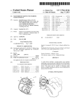
Appendix A – Cable Connectors: Provides a list of PIN connectors.
Appendix B – Modem Installation: Describes how to install and
initialize a modem connected to the GTU and a modem connected to
the PC. It also provides examples of modem versus initial
commands.
Contents
Chapter 1 - System Overview ..................................................................1-1
Introduction ........................................................................................... 1-2
Why CMAP 8010?......................................................................................... 1-2
Introduction to MultiGain Wireless ......................................................... 1-5
Chapter 2 - Installation .............................................................................2-1
Minimum Hardware Requirements .......................................................... 2-2
Software Installation............................................................................... 2-3
CMAP 8010 Installation................................................................................ 2-3
Hardware connections ............................................................................ 2-9
Chapter 3 - Operations .............................................................................3-1
Getting Started....................................................................................... 3-2
Screen Description ................................................................................. 3-4
Screen Operation .................................................................................... 3-7
GTU Unit Display and Description ........................................................... 3-9
Unit Display ................................................................................................. 3-9
SHELF MENU ............................................................................................ 3-10
Chapter 4 - Main Menu .............................................................................4-1
File......................................................................................................... 4-2
Edit ........................................................................................................ 4-3
Configuration ......................................................................................... 4-4
GTU Provisioning ......................................................................................... 4-4
Contents
Unit Display and Status.............................................................................4-4
Freq. Series...................................................................................................4-6
GTU Details ..................................................................................................4-7
Time and Date ..............................................................................................4-7
GPS Provisioning ..........................................................................................4-8
Unit Status ...................................................................................................4-8
Antenna Position ..........................................................................................4-9
GPS Details ................................................................................................4-10
Satellite Status ...........................................................................................4-11
Security................................................................................................ 4-12
General.......................................................................................................4-12
Login ..........................................................................................................4-12
LogOut .......................................................................................................4-13
Menu Access...............................................................................................4-13
Security Alarm............................................................................................4-15
Access Log ..................................................................................................4-16
Options................................................................................................. 4-17
General.......................................................................................................4-17
Comm Features ..........................................................................................4-17
Modem Command.......................................................................................4-19
Modem Operation .......................................................................................4-20
Help...................................................................................................... 4-22
Chapter 5 - Alarm Log ............................................................................. 5-1
General ................................................................................................... 5-2
Screen Description.................................................................................. 5-3
Menu > File............................................................................................. 5-7
Rebuilding Database.....................................................................................5-7
Printing Reports............................................................................................5-8
Define Filter ........................................................................................... 5-9
Queries ................................................................................................. 5-12
Print Button Option ....................................................................................5-14
Export Button Option .................................................................................5-15
Print Destination - Printer ..........................................................................5-18
Print Destination – File ...............................................................................5-18
Menu > View...............................................................................................5-20
Menu > Attend ............................................................................................5-20
Menu > Clear ..............................................................................................5-21
CMAP 8010 - GSS Maintenance
ii
Contents
Menu > Help .............................................................................................. 5-22
Appendix A - Cable Connectors ............................................................. A-1
List of Cables .......................................................................................... A-2
Pin Connections ........................................................................................... A-2
Cable #1....................................................................................................... A-2
Cable #2....................................................................................................... A-2
Cable #3....................................................................................................... A-3
Appendix B - Modem Installation ........................................................... B-1
Initialization of Modem Connected to the GTU........................................ B-2
Initialization of Modem Connected to the PC .......................................... B-3
Modem Versus Initial Command (Examples) ............................................ B-4
Revision 1.0
iii
Figures
Figure 1-1: CraftMap Interface (CMAP 8010 Network View) ................................ 1-2
Figure 2-1: CraftMap Interface (CMAP 8010 Network View) ................................ 2-4
Figure 2-2: Attention Popup Window.................................................................. 2-4
Figure 2-3, CMAP 8010 "Welcome" popup window. ............................................ 2-5
Figure 2-4, CMAP 8010 "Ready to Install" popup window. .................................. 2-5
Figure 2-5: Installing popup window. ................................................................. 2-6
Figure 2-6: Icon on Desktop popup window. ...................................................... 2-6
Figure 2-7: Setup INI Pop-up Window ................................................................ 2-6
Figure 2-8: Select Kind of Communication popup window.................................. 2-7
Figure 2-9: COM PORT Information popup window. ........................................... 2-7
Figure 2-10: Installation Complete popup window.............................................. 2-7
Figure 2-11: Install message box........................................................................ 2-8
Figure 2-12: Database Properties popup window................................................ 2-8
Figure 2-13: PC to GTU Shelf Network ............................................................... 2-9
Figure 3-1: CraftMap Login - Opening Screen .................................................... 3-2
Figure 3-2: Cautionary Message (CMAP 8010).................................................... 3-2
Figure 3-3: CMAP 8010 Full Screen ................................................................... 3-3
Figure 3-4: Properties Window ........................................................................... 3-5
Figure 3-5: CMAP 8010 Message Window........................................................... 3-5
Figure 3-6: Typical Multi Screen Display (CMAP 8010)....................................... 3-8
Figure 3-7: CMAP 8010 "Window is Locked" Message......................................... 3-8
Figure 3-8: GTU Unit Display............................................................................. 3-9
Figure 4-1: File Item in the Menu Bar ................................................................ 4-2
Figures
Figure 4-2: CMAP 8010 End Of Session Message................................................4-2
Figure 4-3: Edit Item in the Menu ......................................................................4-3
Figure 4-4: GTU Shelf.........................................................................................4-4
Figure 4-5: GTU Status Window .........................................................................4-5
Figure 4-6: Configuration Item in the Main Menu ...............................................4-5
Figure 4-7: Frequency Series Window.................................................................4-6
Figure 4-8: CMAP 8010 Message ........................................................................4-6
Figure 4-9: GTU Details Window.........................................................................4-7
Figure 4-10: GTU Time & Date Window ..............................................................4-7
Figure 4-11: GPS Status Window........................................................................4-8
Figure 4-12: Provisioning Sub Menu...................................................................4-9
Figure 4-13: GPS Antenna Position Window .......................................................4-9
Figure 4-14: GPS Details Window .....................................................................4-10
Figure 4-15: GPS Satellite Details Window........................................................4-11
Figure 4-16: Security Item in the Main Menu ...................................................4-12
Figure 4-17: LOGIN pop-up window .................................................................4-12
Figure 4-18: Logged-out Message (CMAP-8010) ................................................4-13
Figure 4-19: SECURITY - ACCESS Pop-up Window ..........................................4-13
Figure 4-20: SECURITY ALARM Pop-up Window ..............................................4-15
Figure 4-21: SECURITY ACCESS LOG Pop-up Window.....................................4-16
Figure 4-22: CMAP-8010 Message Pop-up Window ...........................................4-16
Figure 4-23: Options Item in the Main Menu ....................................................4-17
Figure 4-24: Comm Features Pop-up Window l.................................................4-17
Figure 4-25: Comm Features Pop-up Window II................................................4-18
Figure 4-26: Modem Items in the Options Menu ...............................................4-19
Figure 4-27: Modem Information Window .........................................................4-19
Figure 4-28: Modem operation Window ............................................................4-20
Figure 4-29: Address Book Window ..................................................................4-20
Figure 4-30: About CraftMap Pop-up Window...................................................4-22
CMAP 8010 - GSS Maintenance
ii
Figures
Figure 5-1: Alarm Log ........................................................................................ 5-3
Figure 5-2: File Item in the Menu Bar ................................................................ 5-7
Figure 5-3: Rebuild Database Pop-up Window ................................................... 5-7
Figure 5-4: Print - Report Options Pop-up Window............................................. 5-8
Figure 5-5: Select Filter Options Window ........................................................... 5-9
Figure 5-6: Select Filter Options – Sort By Frame............................................... 5-9
Figure 5-7: Select Filter Options – Filter Selection Frame ................................. 5-10
Figure 5-8: Alarm Log (Subject to Filter Conditions) ......................................... 5-11
Figure 5-9: Enter Filter Name Pop-up Window ................................................. 5-11
Figure 5-10: Queries Pop-up Window............................................................... 5-12
Figure 5-11: Print – Report Options popup window .......................................... 5-13
Figure 5-12: Alarm Report Pop-up Window ...................................................... 5-13
Figure 5-13: Print Pop-up Window ................................................................... 5-14
Figure 5-14: Export Pop-up Window (Export) ................................................... 5-15
Figure 5-15: Format Drop-Down List Box......................................................... 5-15
Figure 5-16: Choose Export File Pop-up Window.............................................. 5-16
Figure 5-17: Export Pop-up Window (Attach) ................................................... 5-16
Figure 5-18: Character-Separated Values Window ........................................... 5-16
Figure 5-19: Number and Date Format Dialog Window .................................... 5-17
Figure 5-20: Send Mail Window ....................................................................... 5-17
Figure 5-21: Enter The Report File Name Window ............................................ 5-18
Figure 5-22: Print Pop-up Window ................................................................... 5-19
Figure 5-23: Printing Pop-up Window .............................................................. 5-19
Figure 5-24: View Item in the Menu Bar........................................................... 5-20
Figure 5-25: Attend Item in the Menu Bar........................................................ 5-20
Figure 5-26: CMAP-8010 Message.................................................................... 5-21
Figure 5-27: Clear Item in the Menu Bar.......................................................... 5-21
Figure 5-28: CMAP-8010 Message.................................................................... 5-21
Revision 1.0
iii
Tables
Table 1-1: CMAP 8010 Main Menu..................................................................... 1-4
Table 3-1: Command Button Bar Functions....................................................... 3-4
Table 3-2: Map Item Alarm Status ..................................................................... 3-6
Table 3-3: Unit LEDs ....................................................................................... 3-10
Table 5-1: Severity ............................................................................................. 5-4
Table 5-2: Basic Parameters............................................................................... 5-5
Table 5-3: Alarm Types and Probable Cause ...................................................... 5-5
Table A-1: List of Cables .................................................................................... A-2
Table A-2: Cable #1............................................................................................ A-2
Table A-3: Cable #2............................................................................................ A-2
Table A-4: Cable #3............................................................................................ A-3
Table B-1: Modem vs. Initial Command With Modem Connection to PC ............. B-4
Table B-2: Modem vs. Initial Command With Modem Connection to GTU ........... B-5
1
Chapter 1 - System Overview
In this Chapter
Introduction, page 1-2
Introduction to MultiGain Wireless, page1-5
Chapter 1 - System Overview
Introduction
The Global Synchronization System (GSS) enables synchronization of
the time and clock of a group of MGW RPCU's (Radio Port Control Units)
in terms of the frequency series of each RPCU.
The GSS system consists of two units:
1. GTU - The GPS system control unit and clock/timing generator
2. GPS - The navigation system receiver which locks on to several
satellites and retrieves accurate timing and positioning information
for the GSS system
Why CMAP 8010?
There are two ways to travel. You can set out in a general direction and
from there on, rely on your instincts. Alternatively, you can obtain a
map and take it from there. Traveling without a map certainly has its
surprises, but forget about routes and make sure that you have
unlimited time at your disposal. In the age of optimum time
management, the experienced traveler will always have a map at hand
to chart the best course within the available time.
The CMAP 8010 enables effortless site and customer equipment
installation. The program offers the user an easy-to-use Man Machine
Interface. . .
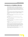
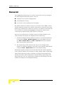
Figure 1-1: CraftMap Interface (CMAP 8010 Network View)
CMAP 8010 - GSS Maintenance
1-2
Introduction
A highly beneficial feature of the program is the enabling of graphic
display of the system and its component parts according to a predefined color classification. Thus, the current alarm status is
ascertained by observing the color display of the element, e.g., a faulty
GTU will display "red." If, for example, the GTU-1 shelf (see Figure 1-1)
displays "red," this signifies a major fault in the unit. The subsequent
stage is to identify the fault and obtain the appropriate solution using
the interactive CraftMap menu. For further information refer to
Chapter 3 - Operations.
A physical display of a shelf is obtained by double clicking on the shelf
icon.
The Windows screen comprises the product logo, menu bar, command
buttons and data entry window: maps, data entry and equipment views.
Revision 1.0
1-3
Chapter 1 - System Overview
The CMAP 8010 Main Menu (see Chapter 4) is itemized below:
Table 1-1: CMAP 8010 Main Menu
ITEM
CONTENTS
File
The "Exit" button for exiting the CraftMap session is included
under this item.
Edit
Lock window
Configuration
Provisioning:
Frequency series*
Antenna position**
GTU details*
GPS details **
Time and date*
Satellite status**
Security
Log-in/log-out
Regulated access to menu items
Options
Comm. Features
Modem Commands
Modem Operation
Help
About CMAP 8010
*
Applicable to GTU provisioning only
** Applicable to GPS provisioning only
CMAP 8010 - GSS Maintenance
1-4
Introduction to MultiGain Wireless
Introduction to MultiGain Wireless
MultiGain Wireless is a Wireless Local Loop (WLL) system, which
utilizes radio links instead of conventional copper based links to
connect telephone subscribers to a local telephone network. The system
provides toll quality voice channels, high quality data facsimile and
modem, and is completely transparent to local exchange services and
signaling. MGW supports a full range of network interfaces and protocol
options.
MGW is not only easy to install and extremely economical, but is often
the only practical solution in areas where copper-based infrastructures
are difficult to implement. MGW can be applied to the following
scenarios:
New urban or suburban housing developments without an existing
copper infrastructure.
Urban environments where copper infrastructure is already
saturated.
Areas where digging in order to lay the foundations for a copperbased system is restricted.
Temporary environments, such as exhibitions and conventions, as
well as disaster zones.
Rural environments, where copper cables may be an expensive
option.
The MGW system is flexible and efficient in its use of the radio
spectrum, and a wide range of optional frequency bands is available.
This allows adaptation to the varying needs of different countries. The
system uses Spread Spectrum Frequency Hopping technology, which
has proved to be highly reliable in many scenarios, including those
characterized by harsh environmental conditions.
MGW can be operated and maintained using the OfficeMap, CraftMap
or SuperOfficeMap network management systems.
Revision 1.0
1-5
2
Chapter 2 - Installation
About this Chapter
Miminum Hardware Requirements, page 2-1
Software Installation, page 2-3
Hardware connections, page 2-9
Chapter 2 - Installation
Minimum Hardware Requirements
PC Pentium 300 MHz, running Windows1 95/98/ME2
64 Mbytes RAM
500 Mbytes hard disk free space
3-1/2" floppy drive
CD-ROM drive
S-VGA graphics adapter card
One serial port
Microsoft or compatible mouse
Eicon S50 X.25 Card Adapter (for X.25 Network)
PC compatible (e.g., 10 Base T, 3Com, etc.) LAN Card Adapter (for
TCP/IP Network)
Parallel printer port and brand compatible printer
17″ monitor (or larger) with graphics accelerator for Windows
1
Windows is a trademark of Microsoft Corporation.
2
Use original English (British Setting) Windows version only.
CMAP 8010 - GSS Maintenance
2-2
Software Installation
Software Installation
Standard CMAP 8010 package consists of the user manual and CD.
Make sure that your PC hard disk is formatted and running Microsoft
Windows 95/98/ME.
IMPORTANT
The PC shall be dedicated to xMAP applications and the application shall be
installed on Drive C:\. Only one version of each xMAP application can be
installed on a given PC. The PC should be used exclusively for network
management system requirements.
Before installing CraftMap, make sure that a printer is installed under
Windows. Do not proceed before you have selected the printer.
Make sure that your Windows display settings calls for Small Fonts so that
CMAP 8010 screens can display maximum information.
CMAP 8010 Installation
1. Switch on your computer and wait for the Win 95/98/ME desktop
to appear.
2. Insert the CD in the appropriate drive.
3. From the Windows Taskbar click the Start button to display the
Start menu.
4. Click Run to open the Run dialog window.
5. Click the Browse button to display the Browse dialog window.
6. From the “Look in” dropdown list, select the CD-Rom drive to
display the CD file contents.
7. Select and open the CMAP 8010 folder.
8. Highlight the SETUP.EXE file and click the Open button to return to
the Run dialog window.
Revision 1.0
2-3
Chapter 2 - Installation
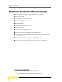
9. Click OK to display the following cautionary message:
Figure 2-1: CraftMap Interface (CMAP 8010 Network View)
10. Click Yes to initiate the installation wizard.
NOTE
Note: It is not necessary to uninstall previous CMAP 8010 installations. If you have a
current CMAP 80!0 installation you are required to respond to the following pop-up
window:
Figure 2-2: Attention Popup Window
Click the Yes button to uninstall the previous version and continue
the installation.
CMAP 8010 - GSS Maintenance
2-4
Software Installation
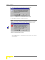
11. The CMAP 8010 Setup "Welcome" popup window is displayed:
Figure 2-3, CMAP 8010 "Welcome" popup window.
12. Click "Next".
13. The CMAP 8010 "Ready to Install" Window is displayed:
Figure 2-4, CMAP 8010 "Ready to Install" popup window.
14. Click "Next".
15. The "Installing" popup window is displayed, allowing the user to
monitor the progress of the installation:
Revision 1.0
2-5
Chapter 2 - Installation
Figure 2-5: Installing popup window.
16. The "Icon on Desktop" popup window is displayed and the user
asked if he wishes the CMAP 8010 shortcut icon to be created on
the desktop:
Figure 2-6: Icon on Desktop popup window.
17. Click Yes to initiate the installation wizard.Click the Yes button to
display the Setup INI pop-up window:
Figure 2-7: Setup INI Pop-up Window
18. Click the Next button to display the "Select Kind of Communication"
popup window, enabling you to define the communications
configuration linking the PC (CMAP 8010) to the GTU-1 module.
CMAP 8010 - GSS Maintenance
2-6
Software Installation
19. Click the button next to "Serial Port" if a direct connection is to be
used or the button next to "Modem" if a modem is to be used:
Figure 2-8: Select Kind of Communication popup window.
20. Click OK to confirm.
21. Next the "COM Port Information" popup window is displayed:
Figure 2-9: COM PORT Information popup window.
22. Select a COM Port by clicking the appropriate button. Click OK to
confirm.
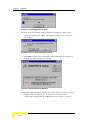
23. The "Installation Complete" popup window is displayed:
Figure 2-10: Installation Complete popup window.
Revision 1.0
2-7
Chapter 2 - Installation
24. Click Finish. The "Install" message box is displayed informing you
that the Windows must be restarted in order for the installation to
be completed.
Figure 2-11: Install message box.
25. Click OK to restart Windows or "Cancel" to return to desktop.
26. In either event, the installation process will be completed only when
Windows is restarted.
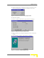
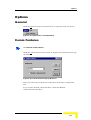
27. The first time CMAP 8010 is run the "Database Properties" popup
window is displayed. The user is requested to select a folder in
which the database is to be located:
Figure 2-12: Database Properties popup window.
28. Follow the instructions in the dialog window, by accepting the
default folder or by selecting a folder of your choice.
29. Press the Apply button to make this information immediately
available to CMAP 8010.
30. Press the OK button to start CMAP 8010.
CMAP 8010 - GSS Maintenance
2-8
Hardware connections
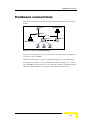
Hardware connections
The PC is connected to the GTU shelf network (CMAP 8010) as shown
below:
GPS-1
OFFICEMAP 8000
GTU-1
RS-485
RPCU-1
RPCU-n
CRAFTMAP 8010
RPU-1
RPU-2
RPU-3
Figure 2-13: PC to GTU Shelf Network
The PC is connected to the rear side of the GTU. The GTU is connected
by cable to the CraftMap.
Optionally, for office or large site global management, the OfficeMap
management software can be connected as shown in Figure 2-1 above.
The OfficeMap can control up to 31 network elements, usually a single
GTU and several RPCU's connected to the RS-485 control bus.
Revision 1.0
2-9
3
Chapter 3 - Operations
In This Chapter
Getting Started, page 3-2
Screen Description, page 3-4
Screen Operation, page 3-7
GTU Unit Display and Description, page 3-9
Chapter 3 - Operations
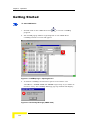
Getting Started
To start CMAP 8010::
1. Double-click on the CMAP 8010 icon
to run the CraftMap
program.
2. The LOGIN popup window superimposed on the CMAP 8010
CraftMap interface screen will appear:
Figure 3-1: CraftMap Login - Opening Screen
3. To initiate CraftMap use Alvarion's preset "User Name" and
"PassWord,": SUPER-USER and ENTER respectively. If you make an
incorrect entry, the CraftMap Message pop-up window will display:
Figure 3-2: Cautionary Message (CMAP 8010)
CMAP 8010 - GSS Maintenance
3-2
Getting Started
NOTE
The user is allowed three attempts. If the third attempt fails, CMAP 8010 will load
automatically, without enabling the user to configure the system!
The system's supervisor should change the "PassWord" immediately using the
"Security/Menu Access" item.
Title Bar
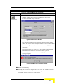
4. Click the OK button to clear the LOGIN pop-up window and display
the CMAP-8010 Full Screen (Figure 3-3):
Main Menu
Toolbar
Multi Screen
Display
Message
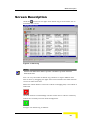
Figure 3-3: CMAP 8010 Full Screen
If the Login procedure is incomplete (the operator cancels or Logout or
enters without menu access), only File, Edit, Security and Help menu
items are enabled.
Revision 1.0
3-3
Chapter 3 - Operations
Screen Description
The CMAP 8010 CraftMap interface comprises the following elements:
Header
The Header bar displays the CMAP 8010 CraftMap identifier
Main Menu
Main menu bar items displayed (and available) are dependent upon
the currently active screen.
Button Bar
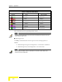
The command button bar functions are defined as:
Table 3-1: Command Button Bar Functions
Command
Up
Home
Root
Exit
Function
Display upper hierarchical level of selected map (not
supported in this version)
Display user's home map selection
Display system root map
Alternative to Main Menu File/Exit item
CMAP 8010 - GSS Maintenance
3-4
Screen Description
Table 3-1: Command Button Bar Functions
Command
Properties
Function
Click to display the properties window with data base
location and disk usage statistics:
Figure 3-4: Properties Window
The properties window, incorporating the Data Base frame,
allows the user to select the path for the location of the CMAP
8010 working database, as well as allocate the appropriate
disk space.
User instructions are spelt out at the bottom of the window.
If the allocation limits are exceeded during system
operations, the user is alerted by an appropriate screen
message display:
Figure 3-5: CMAP 8010 Message Window
Multi screen display
Initially two screens are displayed in this area: the CMAP 8010 map
on the right and the Alarm Log on the left.Map items are colored
according to their respective alarm status:
Revision 1.0
3-5
Chapter 3 - Operations
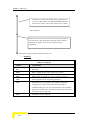
Table 3-2: Map Item Alarm Status
Symbol
Color
Alarm Status
Green
All clear
Red
Major
Crimson
Critical
Yellow
Minor
Purple
Warning
Blue
Unknown
The color indicates the operating alarm status.
NOTE
By clicking on the header bar of each split screen will display the distinctive menu bar
of the respective split screen.
Message Panel
CraftMap communication status is given in the message panel as
follows:
Black foreground, green background ⇒ Connection confirmed.
Black foreground, red background ⇒ No connection.
NOTE
When initiating the CMAP, wait for confirmation of connection, which takes a few
seconds to reach a stable state.
CMAP 8010 - GSS Maintenance
3-6
Screen Operation
Screen Operation
Basic screen management:
Click the
button in the top right hand corner to reduce screen
window.
Click the
button to close the session and exit the screen
Click the
button in the top right hand corner of the screen to
convert the main screen to CMAP 8010 icon in the desktop taskbar.
Click the icon to restore the Main Screen.
Click the
button in the top right hand corner of the screen to
maximize screen size.
Menu items can be activated either by:
1. Clicking the menu item, or
2. Pressing the Alt key and the underlined letter in the item (e.g.,
Alt+S, to open the Security sub menu).
3. Double-click the GTU to display the "physical" shelf and the LED
display.
NOTE
By clicking on the header bar of each split screen will display the distinctive menu bar
of the respective split screen.
Message box
CraftMap communication status is given in the message box as
follows:
Black foreground, green background ⇒ Connection confirmed.
Black foreground, red background ⇒ No connection.
NOTE
When initiating the CMAP, wait for confirmation of connection, which takes a few
seconds to reach a stable state.
Menu items can be activated either by:
1. Clicking the menu item, or
2. Pressing the Alt key and the underlined letter in the item (e.g.,
Alt+S, to open the Security sub menu).
Revision 1.0
3-7
Chapter 3 - Operations
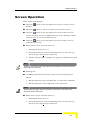
The multi screen display can accommodate more than two screens
simultaneously:
Figure 3-6: Typical Multi Screen Display (CMAP 8010)
NOTE
To reduce the multi screen display to two or less, double click the Close button of a
given screen to close the respective screen and obtain a 2-screen display.
When a new screen is opened, it occupies the whole multi-screen
display area.
Press the
button to the right of the Menu bar to display the original
two screens and the new screen.
Attempting to close down a locked screen (see Map Menu → Edit item)
will display the following message:
Figure 3-7: CMAP 8010 "Window is Locked" Message
In order to unlock a locked screen, the user must click the Edit item in
the Main Menu, and click the Lock window menu item (see Chapter 5 Edit).
CMAP 8010 - GSS Maintenance
3-8
GTU Unit Display and Description
GTU Unit Display and Description
Unit Display
To to display the GTU unit configuration:
Double-click the GTU item in the main network.
Menu
SHELF ID and
Severity
Unit LED's
Figure 3-8: GTU Unit Display
The SHELF ID box is displayed in the top left hand corner of the shelf
display (see Figure 3-8). The name background color indicates the
current summarized alarm status (Chapter 5 - Alarm Log).
Revision 1.0
3-9
Chapter 3 - Operations
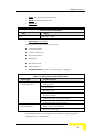
Unit LEDs are defined below:
Table 3-3: Unit LEDs
LED
Color
Status
OOS
Red
Out Of Service
PWR
Green
Power supply active
MJR
Red
Major alarm
MNR
Yellow
Minor alarm
SYNC
Red
No synchronization with GPS system
ACO
Green
Alarm CutOff active
SHELF MENU
For a description of the following shelf menu options, refer to Chapter 4.
File
Edit
Configuration
Security
Options
Help
CMAP 8010 - GSS Maintenance
3-10
4
Chapter 4 - Main Menu
In This Chapter
File, page 4-2
Edit, page 4-3
Configuration, page 4-4
Security, page 4-12
Options, page 4-17
Help, page 4-22
Chapter 4 - Main Menu
File
To exit CMAP 8010:
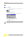
1. Click the "File" item in the Menu bar to open the drop down menu,
comprising the "Exit" item:
Figure 4-1: File Item in the Menu Bar
2. Click the "Exit" item to display the following pop-up message:
Figure 4-2: CMAP 8010 End Of Session Message
3. Press "OK" to quit CMAP.
4. Press "Cancel" to return to CMAP.
NOTE
You can also exit CMAP by clicking the Exit button in the button bar immediately below
the main menu.
CMAP 8010 - GSS Maintenance
4-2
Edit
Edit
To lock/unlock a CMAP 8010 window:
1. Click Edit to open the item in the main menu bar to open the drop
down menu:
Figure 4-3: Edit Item in the Menu
The single "Lock window" item is highlighted. The "√" in front of the item
(the main map default) indicates that the active window is locked.
2. Click on the Lock window item to unlock an active window. The "√"
will not appear in front of the item.
NOTE
All sub-maps are unlocked in their default mode.
Revision 1.0
4-3
Chapter 4 - Main Menu
Configuration
GTU Provisioning
Unit Display and Status
To view the GTU unit status:
1. Double-click the GTU icon in the GSS map to display the GTU shelf:
GTU Unit
Figure 4-4: GTU Shelf
CMAP 8010 - GSS Maintenance
4-4
Configuration
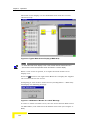
2. Double-click the GTU Unit (see above) to obtain the GTU status
window display:
Figure 4-5: GTU Status Window
The status window is for information only. Press the Cancel button to
return to the GTU shelf screen.
To access the provisioning menu:
Click Configuration in the main menu to display the Provisioning sub
menu item. Click the latter to display the Provisioning sub menu:
Figure 4-6: Configuration Item in the Main Menu
Revision 1.0
4-5
Chapter 4 - Main Menu
Freq. Series
To view/edit the Frequency Series length:
Click the Freq. series item in the Provisioning sub menu to display the
Frequency Series display window:
Figure 4-7: Frequency Series Window
The Frequency Series length can vary between 1 to 80 and should be
identical to the frequency series length of all RPCU's at the same site.
Enter the required length in the Length field and press OK to display
the system-warning message:
Figure 4-8: CMAP 8010 Message
Click the Yes/No button to continue/discontinue and return to the GTU
shelf screen.
Press Cancel to return to the GTU shelf screen without adjusting the
Frequency Series length.
Press Reset to invoke the previous series length.
CMAP 8010 - GSS Maintenance
4-6
Configuration
GTU Details
To view the GTU details display window:
Click the GTU details item in the Provisioning sub menu. The GTU
Details window is displayed:
Figure 4-9: GTU Details Window
The GTU details window is for information only. Press the Cancel button
to return to the GTU shelf screen.
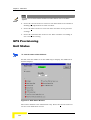
Time and Date
To view/edit time and date:
1. Click the Time and date item in the Provisioning sub menu to
display:
Figure 4-10: GTU Time & Date Window
The GTU Time and Date displayed in the respective fields correspond to
the current GTU setting. If the current setting is as required, press the
OK button to return to the GTU shelf screen.
Revision 1.0
4-7
Chapter 4 - Main Menu
NOTE
The GTU Time and Date settings will affect the Alarm Report when a new alarm
registers.
2. Press the Cancel button to return to the GTU shelf screen without
making any adjustment to time and date.
3. Press the Reset button to reset the time and date to the previous
settings.
4. Press the Load from PC button to set Time and Date according to
the current PC setting.
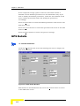
GPS Provisioning
Unit Status
To view the status of the GPS unit:
Double-click the GPS icon in the GSS map to display the GPS status
window display:
Figure 4-11: GPS Status Window
The status window is for information only. Press the Cancel button to
return to the GSS main screen.
CMAP 8010 - GSS Maintenance
4-8
Configuration
To display the Provisioning sub menu item:
Click the Configuration item in the main menu to. Click the latter to
display the Provisioning sub menu:
Figure 4-12: Provisioning Sub Menu
Antenna Position
To view/edit antenna position:
Click the Antenna position item in the Provisioning sub menu to display
the GPS Antenna Position Window:
Figure 4-13: GPS Antenna Position Window
The Position Source frame includes two options:
Computed Average - The GSS automatically calculates its position
according to the average of received satellite information.
User Defined - GSS override, enabling the user to manually enter
positional data.
Revision 1.0
4-9
Chapter 4 - Main Menu
If the Computed Average option is selected, the Position frame is
disabled and the Position parameters are for information only. If you
wish to modify the Position parameters, check the User Defined check
box to enable the Position frame and modify the parameters
accordingly.
Press the OK button to retain the defined parameters and return to the
GSS main screen.
Press the Cancel button to cancel this operation and return to the GSS
main screen.
Press the Reset button to retrieve the previous settings.
GPS Details
To view/edit GPS details:
Click the GPS details item in the Provisioning sub menu to display the
GPS details Window:
Figure 4-14: GPS Details Window
GPS details are for information only. Press the Cancel button to return
to the GSS main screen.
CMAP 8010 - GSS Maintenance
4-10
Configuration
Satellite Status
To view/edit satellite status:
Click the Satellite status item in the Provisioning sub menu to display
the GPS Satellite Details Window:
Figure 4-15: GPS Satellite Details Window
The satellite details window can display information for up to six
satellites. Displayed details are for information only.
With reference to the General frame above, the number of In View
Sat(ellites) is always greater than the number of Tracked Sat(ellites).
Satellite parameters are defined as follows:
S/N - Signal to Noise Ratio
Azimuth - Azimuth of satellite with respect to the GSS location
Elevation - Elevation of satellite with respect to the GSS location
Press the Cancel button to return to the GSS main screen.
Revision 1.0
4-11
Chapter 4 - Main Menu
Security
General
Under this menu item the user can control system log-in and log-out
operations, regulate access to menu items according to varying levels of
responsibility and seniority (performed by the CraftMap supervisor via
the Security/Menu Access item)
Click the Security item in the main menu to open the item sub menu:
Figure 4-16: Security Item in the Main Menu
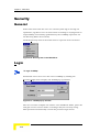
Login
To login CraftMap:
Authorized users can access the active CraftMap by clicking the
Security/Login item to display the LOGIN pop-up window:
Figure 4-17: LOGIN pop-up window
The user can then complete the "Name" and "PassWord" fields, press OK
and gain access to menu items according to his/her security rating.
This operation automatically cancels the previous Login action.
CMAP 8010 - GSS Maintenance
4-12
Security
LogOut
To logout CraftMap:
Click the logOut item to display the pop-up window:
Figure 4-18: Logged-out Message (CMAP-8010)
Menu Access
To view/edit security access parameters:
1. Click the Menu access item to display the LOGIN pop-up window.
2. Complete the "Name" and "PassWord" fields and press the OK
button to display the SECURITY ACCESS window (only accredited
supervisors can access this window):
Figure 4-19: SECURITY - ACCESS Pop-up Window
Revision 1.0
4-13
Chapter 4 - Main Menu
The SECURITY - ACCESS window allows the supervisor(s) to regulate
CraftMap availability in terms of "User Details" and "Menu Access."
3. In the "User Details" frame, the supervisor can type in the relevant
"User Name" and "PassWord" for all potential users. Turning to the
"Menu Access" frame, each item is listed under two categories: GET
and SET, denoting data retrieval and database modification
respectively.
4. In Figure 4-21 the category check boxes are all checked, indicating
"access granted." To enable a category, the supervisor must click the
check box to display a .
5. When the Menu Access list is complete, press "Apply" to confirm
settings.
The "Operation" frame contains three items:
Add
Edit
Delete.
Clicking "Add" will nullify all the Menu Access fields and display a blank
"User Name" field.
To Edit or Delete a user:
1. Select the particular user in the "User" drop-down list box and click
the desired "Operation" item.
2. Press the Reset button to reset all fields.
3. Press the Close button to exit the SECURITY - ACCESS window and
return to the previous display.
CMAP 8010 - GSS Maintenance
4-14
Security
Security Alarm
To view security alarms list:
Click the Security alarm item to display the SECURITY ALARM window:
Figure 4-20: SECURITY ALARM Pop-up Window
This window displays a list of failed CraftMap access attempts in terms
of Attempt #, Date of Attempt, User Name and Password.
Press the Close button to exit and return to the main screen.
Revision 1.0
4-15
Chapter 4 - Main Menu
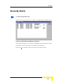
Access Log
To view access log:
Click the Access log item to display:
Figure 4-21: SECURITY ACCESS LOG Pop-up Window
This window displays a list of all CraftMap access attempts and
categorizes them according to PASS, FAIL and OUT (LogOut).
Browse through the list using the vertical scroll bar on the right of the
window.
The window contains two control buttons: Close and Clear.
If you wish to clear the list, press the Clear button to display the clear
SECURITY LOG FILE confirmation pop-up window:
Figure 4-22: CMAP-8010 Message Pop-up Window
Press the Yes button if you wish to clear the security log file.
Press the No button if you do not wish to clear the security log file.
Press the Close button to exit and return to the main screen.
CMAP 8010 - GSS Maintenance
4-16
Options
Options
General
Click the Options item in the main menu to open the item sub menu:
Figure 4-23: Options Item in the Main Menu
Comm Features
To view/edit comm features:
Click the Comm features menu item to display the Comm Features popup window:
Figure 4-24: Comm Features Pop-up Window l
Select the relevant port from the Comm Port drop-down combination
box.
If you require modem communication, check the Modem
communication checkbox.
Revision 1.0
4-17
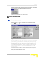
Chapter 4 - Main Menu
The Check Modem Communication pane opens up and the system
checks the modem connection status of your PC:
Figure 4-25: Comm Features Pop-up Window II
In Figure 4-25, the system indicates that a modem is attached to
COM2, which is confirmed by the Comm Port drop down list box.
Click the OK button to return to the main screen.
NOTE
Selection of the Modem communication option will result in the modem icon:
being displayed in the button bar:
Additionally, a "Modem" box will appear alongside the "Comm" box at the bottom right
hand corner of the main screen. The "modem" box color scheme is as follows: black
foreground, green background confirms modem connection; black foreground, red
background denotes no modem connection.
Press the "Cancel" button to abandon the operation and return to the
previous display.
Press the "Reset" button to recall the current comm. port setting.
CMAP 8010 - GSS Maintenance
4-18
Options
If modem communication has been selected and confirmed, the Options
menu will include two additional modem-related items:
Figure 4-26: Modem Items in the Options Menu
Modem Command
To view modem commands:
Click the Options → Modem commands item to display the Modem
Information window:
Figure 4-27: Modem Information Window
The user should add a delay time of between 1 and 2.5 secs, dependent
upon modem type, after the ATDT command (delay before proceeding
with dialing). The delay time will vary from modem to modem. In the
case of Motorola modem types, a tilde ("~") should be added for every
0.125 secs delay, whereas in the case of US ROBOTICS, a "/" sign
should be added.
Check the Automatic re-dial at startup box if this option is required.
Click OK to return to the main screen.
Revision 1.0
4-19
Chapter 4 - Main Menu
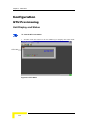
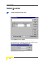
Modem Operation
To initiate communications via the modem:
Click the Options → Modem operation item to display the Modem
operation dialog window:
Figure 4-28: Modem operation Window
Phone numbers can be added, deleted and updated, using the
appropriate buttons in the Phone list frame. To add a number, click the
Add button to open the Address Book dialog window:
Figure 4-29: Address Book Window
CMAP 8010 - GSS Maintenance
4-20
Options
Fill in the site name and phone number and press OK to return to the
Modem operation window. The last called number is shown at the top of
the list.
To delete or update a site and/or number, highlight the appropriate row
in the list and press the Delete or Update buttons accordingly.
To communicate with a given site, highlight the site and hit the Dial
button to initiate the call. Once the call is initiated, the Disconnect
button is enabled. Hit the Disconnect button to terminate the call.
Hit the Dial whom button to manually dial a number.
If you wish to abort the call, hit the Abort button.
To re-dial a number, hit the Re-dial button.
Check the Disconnect after (HH:MM) box and enter the required time if
this option is required.
Press the Modem Commands button to display modem information.
Press the Close button to return to the main screen.
Revision 1.0
4-21
Chapter 4 - Main Menu
Help
Click the Help → About item in the Main Menu to display summary
information about CraftMap and the Network Management Interface:
Figure 4-30: About CraftMap Pop-up Window
If the system resources fall below a threshold of 30%, the available
system resources are at a critical level and the user is strongly advised
to unload unnecessary programs from the system, thereby recovering
system resources.
CMAP 8010 - GSS Maintenance
4-22
5
Chapter 5 - Alarm Log
In This Chapter
General, page 5-2
Screen Description, page 5-3
Menu > File, page 5-7
Define Filter, page 5-9
Queries, page 5-12
Chapter 5 - Alarm Log
General
The CMAP 8010 Alarm Log is a visual record of all events occurring in
the Global Synchronization system, such as:
Changes to the system configuration
Card definition activity
Occurrence and rectification of card faults
By default, alarms are listed as they are received by the CMAP control
system with time stamp in accordance with the PC's internal clock. The
Alarm Log scrolls down as fresh occurrences are added to the alarm list.
A new alarm is automatically highlighted irrespective of the user's
current preoccupation with earlier alarm occurrences.
The user can intervene in a number of ways to make changes to the
order in which the alarms are displayed in the Alarm Log:
1. Automatic display of fresh alarm occurrences can be suspended by
activating the View > Enable updates menu item (Menu>View) or
the View > Define filter and View > Queries menu items (Define
Filter and Queries respectively).
2. The sequencing of the alarms in the Log can be changed with
respect to column headings to meet the user's specific requirements
using the View > Define filter menu item (Define Filter).
The Alarm Log time stamp is the actual time that the alarm originates
in the system. Alarms can, from time to time, display with varying delay
times in the Alarm Log. Thus, an alarm can appear in the Alarm Log,
bearing an earlier time stamp than an alarm already appearing in the
Alarm Log. The user can amend this anomaly by intervening to list the
alarms according to ascending Time Stamp.
CMAP 8010 - GSS Maintenance
5-2
Screen Description
Screen Description
Click the
button on the right of the Alarm Log screen header bar to
maximize the screen:
Figure 5-1: Alarm Log
NOTE
The Menu bar relates to the Alarm Log screen. The Alarm Log screen cannot be
closed by the user.
You can vary the width of Alarm Log columns to expose hidden data.
This is done by dragging the right hand vertical frame line limit with the
cursor in either direction.
When the "Alarm Status" button face shows a swinging bell, a new alarm is
indicated:
Click the button to acknowledge and the button face to show a stationary
bell on the currently severest alarm background:
Navigate the Alarm Log as follows:
Revision 1.0
5-3
Chapter 5 - Alarm Log
Scroll up or down the Alarm Log by placing the
cursor on this slide, and while holding down the
left mouse button, move the mouse up or down.
Alternatively….
Place the cursor on the arrow at the top or bottom of
the scroll bar and hold down the left mouse button
until the required section of the Alarm Log is
displayed.
The Alarm Log tabulates alarms in terms of:
1. Severity:
Table 5-1: Severity
Alarm
Description
Wrn
Warning
MNR
Minor single fault in the reporting element
MJR
Major fault on board or in the reporting element
CRIT
Critical (fault in the reporting element)
CLR
Problem resolved (applies to problems originally
assigned a severity level). The CLR message is
automatically given by the system when the problem
has been solved either automatically by the system or
manually by the operator
UNK
Unknown source of fault
CMAP 8010 - GSS Maintenance
5-4
Screen Description
2. Time: Time stamp (time and date)
3. NE ID: Network Element ID
4. Object ID:
Table 5-2: Basic Parameters
Type
Object
Unit
GSS, GTU, GPS
5. Alarm Type (examples):
List of possible types of alarm categories –
Communication
Quality of Service
Processing Error
Equipment
Environmental
Undetermined
6. Probable Cause (in terms of Alarm Type - examples):
Table 5-3: Alarm Types and Probable Cause
Alarm Type
Communication
Probable Cause
Loss of signal
Loss of frame
Framing error
Degraded signal
Communication subsystem failure
Communication protocol error
Environmental
Temperature unacceptable
Enclosure door open
The probable cause is self explanatory, without requiring further
amplification or qualification.
Revision 1.0
5-5
Chapter 5 - Alarm Log
7. Additional Text:
Further information on the Probable Alarm Cause.
The Alarm Report Summary is displayed in four adjacent boxes at the
base of the table. The display enables the operator to monitor
occurrence of new alarms in the system. The information is recorded on
the hard disk and can be reviewed and erased by the operator as
required.
NOTE
When the modem is in use, an additional Site column is displayed, denoting the name
of the currently connected site dialed from the modem address book.
CMAP 8010 - GSS Maintenance
5-6
Menu > File
Menu > File
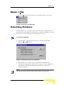
Click on the File item in the menu bar to display the File sub menu:
Figure 5-2: File Item in the Menu Bar
Rebuilding Database
"Rebuild Database" is invoked when there is reason to believe that the
database has been affected in some way or other. For example, data has
been cleared or the database is behaving unevenly, etc.
To rebuild the database:
1. Click the File > Rebuild Database item to display the Rebuild
Database pop-up window:
Figure 5-3: Rebuild Database Pop-up Window
2. Select either one or both current and historical databases by
checking the appropriate check boxes and press "OK" to implement
your request. Check "Keep Backup of Database" to generate
database backup.
NOTE
This item should be invoked after a large number of actions have been taken.
Revision 1.0
5-7
Chapter 5 - Alarm Log
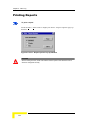
Printing Reports
To print a report:
Click the File > Print item to display the Print - Report Options pop-up
window:
Figure 5-4: Print - Report Options Pop-up Window
WARNING
Before invoking this item, make sure that the Printers option in the Windows Control
Panel are configured correctly.
CMAP 8010 - GSS Maintenance
5-8
Define Filter
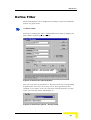
Define Filter
Alarm information can be displayed according to selected conditions
and in any given order.
To define a filter:
Proceed by clicking the View > Define filter menu item to display the
Select Filter Options pop-up window:
Figure 5-5: Select Filter Options Window
The user can select a parameter to "Sort By" from the corresponding
dropdown list box. You can sort by one or more parameters. For
example, if you select to sort by Obj Class and Obj Instance, in that
order, the "Sort By" frame will display as:
Figure 5-6: Select Filter Options – Sort By Frame.
Revision 1.0
5-9
Chapter 5 - Alarm Log
According to this selection the alarms will be listed primarily by Obj
Class and secondarily, by Obj Instance.
Proceed to set an initial condition in the Filter Conditions frame,
entering the required values in the Field Name, Condition and Enter
Value fields. Click the Add Condition button to enter the condition into
the Selected Condition window.
NOTE
Before selecting "Obj Class" under Field Conditions/Field Name, the "Ne Type" should
be specified, in order to display the appropriate details.
You can compound the filter conditions by selecting an appropriate Find
radio button (Or/And/(…) Or /(…) And), setting a new condition,
revising the previously selected condition (see Figure 5-5).
A more complex example is given below:
Set Obj Instance = 3.1 Or Obj Instance = 6.2 (…) And Obj Class = RPCU
to obtain the following Selected Condition:
Figure 5-7: Select Filter Options – Filter Selection Frame
NOTE
The (…) Or and (…) And commands show all previous conditions in parentheses.
CMAP 8010 - GSS Maintenance
5-10
Define Filter
Click the Go button to display the Alarm Log subject to the selected
filter condition/s:
Figure 5-8: Alarm Log (Subject to Filter Conditions)
The selected filter conditions are defined above the alarm log.
If you wish to save the selected filter conditions for further reference,
then before clicking the Go button, check the "Save Current Filter in
Query" checkbox to display the Enter Filter Name pop-up window:
Figure 5-9: Enter Filter Name Pop-up Window
Enter a name and click the OK button to display the Alarm Log subject
to the selected filter condition/s (see Figure 5-8 above).
NOTE
When a filter is in use, the screen will not update automatically. When a new alarm
registers, the user should click the oscillating bell to refresh the screen. Only alarms
that meet the filter conditions will then display.
Revision 1.0
5-11
Chapter 5 - Alarm Log
Queries
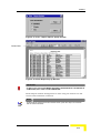
To define queries:
Click the View > Queries menu item to display the Queries To Filter
Alarm Log pop-up window:
Figure 5-10: Queries Pop-up Window
The Queries List window lists the sets of alarm filter conditions defined
by the user. Highlight a given Query and click the Ok button to display
the Alarm Log subject to selected filter condition/s (see Figure 5-8
above).
To delete a Query from the Queries List window, highlight the given
query and click the Delete button to expedite.
Check the "Window" box in the "Print to panel" frame and press the
Print button to display the Alarm Report pop-up window:
CMAP 8010 - GSS Maintenance
5-12
Queries
Figure 5-11: Print – Report Options popup window
Button Bars
Figure 5-12: Alarm Report Pop-up Window
IMPORTANT
DO NOT CLICK THE CLOSE MENU ITEM UNTIL PAGINATION OF THE REPORT IS
COMPLETED (THE "STOP" ICON IS DISABLED).
Alarm Report window management is done using the button bar and
vertical and horizontal scroll bars.
NOTE
To terminate the report process and exit the screen, press the "Stop" icon and then
click the Close menu item.
Revision 1.0
5-13
Chapter 5 - Alarm Log
The button bar's functions are described below:
Go To Start
of Report
Page Up
Zoom
Export
Page Down
Go to end of
Report
Print Button
Stop Button
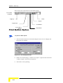
Print Button Option
To print an alarm report:
1. Click the Print button in the Alarm Report button bar to display the
Print pop-up window:
Figure 5-13: Print Pop-up Window
2. Define the "Print Range," number of "Copies" required and check the
"Collate Copies" check box if required.
3. Click OK to start printing.
CMAP 8010 - GSS Maintenance
5-14
Queries
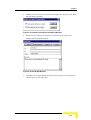
Export Button Option
To export an alarm report:
1. Click the Export button in the Alarm Report button bar to display
the Export pop-up window:
Figure 5-14: Export Pop-up Window (Export)
You can export the report according to your selection from a choice of
standard formats listed in the Format drop-down list box:
Figure 5-15: Format Drop-Down List Box
Assuming that you select the "Excel 5.0 (XLS)" format, click OK to
display the Choose Export File pop-up window:
Revision 1.0
5-15
Chapter 5 - Alarm Log
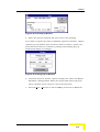
Figure 5-16: Choose Export File Pop-up Window
2. Select a folder using the "Save in" browser drop-down list box and
name the file in the "File name" box.
3. Click Save to export the alarm report and return to the Alarm Log
screen.
If Internet mail is installed in the PC, the user can select the Microsoft
Mail (MAPI) destination option from the Destination dropdown list box:
Figure 5-17: Export Pop-up Window (Attach)
4. Select the required format from the "Format" drop-down list box and
click OK to display the Character-Separated Values window (for
example):
Figure 5-18: Character-Separated Values Window
CMAP 8010 - GSS Maintenance
5-16
Queries
5. Modify/accept values and click OK to display the Number and Date
Format Dialog window:
Figure 5-19: Number and Date Format Dialog Window
6. Mark or leave empty the respective check box and click OK to
display the Send mail window:
Figure 5-20: Send Mail Window
7. Complete the computerized form and click "Send" to mail attached
alarm report to the addressee.
Revision 1.0
5-17
Chapter 5 - Alarm Log
Print Destination - Printer
If you wish to print directly, check the "Print Destination: Printer" radio
button and click the Print button to commence printing.
Print Destination – File
To to print to file:
1. Check the "Print Destination: File" radio button and click the Print
button to display the Enter The Report File Name window:
Figure 5-21: Enter The Report File Name Window
2. Chose a folder to "Save in," enter a "File name" and click the Save
button to create the file.
NOTE
When printing directly to "File", ASCII format is the only available format under
"Save as type:". If another format is required, use the "Print Destination – Window"
option from the Print – Report Options pop-up window..
3. Use the vertical and horizontal scroll bars to scroll through the
report.
4. Press the Print button in the Alarm Report button bar to display the
Print (control) pop-up window:
CMAP 8010 - GSS Maintenance
5-18
Queries
Figure 5-22: Print Pop-up Window
5. Select the options required and press OK to start printing.
If you wish to bypass the "Print to: Window" option in the Print - Report
Options pop-up window, then check the "Print to: Printer" option and
press the Print button to commence printing. The Printing pop-up
window will display accordingly:
Figure 5-23: Printing Pop-up Window
6. Check the "Print to: Printer" option to display the "Enter the Report
File Name" dialog window. Enter the required file name and press
OK to complete. Press Cancel to cancel the operation.
7. Press the File > Exit item to exit CraftMap and return to Windows.
Revision 1.0
5-19
Chapter 5 - Alarm Log
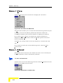
Menu > View
Click the View item in the menu bar to display the sub menu:
Figure 5-24: View Item in the Menu Bar
The View item enables you to review the two databases generated by the
CraftMap: Current and History (historical) databases. When the
CraftMap is initiated, the Current database is displayed as default.
If you select View > History, the Alarm Log - History database is
displayed and the Attend menu item and Enable updates sub menu
item are disabled.
Click Sort by creation time to sort the database by creation date and
time.
If you wish to review the Current alarm log status, click the View >
Current item.
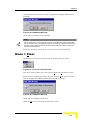
Menu > Attend
The Attend item in the menu bar enables the user to save selected/all
Current database events in the History database.
To save a selected event:
Click on the event in the Alarm log and then click the Attend item in the
menu bar to display the sub menu:
Figure 5-25: Attend Item in the Menu Bar
CMAP 8010 - GSS Maintenance
5-20
Queries
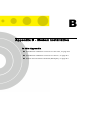
Click the Selected sub menu item to display the CMAP confirmation
message:
Figure 5-26: CMAP-8010 Message
Click "OK" to confirm your selection.
NOTE
You can select one or more events in sequence by dragging the cursor from the first
event to the last event in the selected sequence. Alternatively, click the first event that
you wish to select and then press and hold down the Shift button while you click the
last event in the sequence.
Press the All sub menu item to save all events in the Alarm log.
Menu > Clear
Click the Clear item in the menu bar to display the sub menu:
Figure 5-27: Clear Item in the Menu Bar
The Clear item enables the user to delete Selected/All alarm events.
Select events as described above (0) and click the Selected sub menu
item to display the CMAP confirmation message prompt:
Figure 5-28: CMAP-8010 Message
Click "OK" to complete the action.
Click the All sub menu item to delete all events.
Revision 1.0
5-21
Chapter 5 - Alarm Log
Menu > Help
See Chapter 4.
CMAP 8010 - GSS Maintenance
5-22
A
Appendix A - Cable Connectors
In this Appendix
List of Cables, on page A-2
Appendix A - Cable Connectors
List of Cables
Table A-1: List of Cables
Cable#
Path
Catalog#
1
CMAP 8010 to Modem
2
Modem to GTU
3
CMAP 8010 to GTU
Pin Connections
All connectors are D type.
Cable #1
Table A-2: Cable #1
PC
Modem
25 pin (female)
25 pin (male)
Full pin-to-pin connection
Cable #2
Table A-3: Cable #2
Modem
GTU
25 pin (male)
9 pin (male)
2
←→
3
3
←→
2
7
←→
5
8
←→
4
CMAP 8010 - GSS Maintenance
A-2
List of Cables
Cable #3
Table A-4: Cable #3
PC
9 pin (female)
GTU
25 pin
(female)
9 pin
(male)
2
←→
2
←→
3
3
←→
3
←→
2
5
←→
7
←→
5
Revision 1.0
A-3
B
Appendix B - Modem Installation
In this Appendix
Initialization of Modem Connected to the GTU, on page B-2
Initialization of Modem Connected to the PC, on page B-3
Modem Versus Initial Command (Examples), on page B-4
Appendix B - Modem Installation
Initialization of Modem Connected to
the GTU
To initialize a modem connected to the GTU:
1. No X-ON/X-OFF
2. No CTS/RTS
3. Ignore DTR
4. "AUTO ANSWER MODE" mandatory
5. Both modems, one connected to the GTU, the other connected to the
PC, must be defined as either CCITT or BELL mode.
6. CARRIER On
7. These characteristics must be saved in the modem's non-volatile
memory.
8. ASCII Return Code.
CMAP 8010 - GSS Maintenance
B-2
Initialization of Modem Connected to the PC
Initialization of Modem Connected to
the PC
To initialize a modem connected to the PC:
1. No X-ON/X-OFF
2. No CTS/RTS
3. "DIAL MODE" mandatory
4. Both modems, one connected to the GTU, the other connected to the
PC, must be defined as either CCITT or BELL mode.
5. CARRIER On
6. This configuration should be entered under the "COMM-FEATURES"
option
7. ASCII Return Code.
Revision 1.0
B-3
Appendix B - Modem Installation
Modem Versus Initial Command
(Examples)
For modem connection to PC:
Table B-1: Modem vs. Initial Command With Modem Connection to PC
Modem
Initial Command
Motorola 8396 (1200 bps)
&F&E0&C1&D2%H1%S3%R2*L
RAD DLM-AT (dial)
X4
Hayes V-series ultra:
SmartModem 9600
&F&D0&C1&K0&R1X4
Hayes SmartModem 2400
&F&D0L0&R1X4S0=1V1
Microcom QX V.32c
&F&D0%C0\V0X4
Multitech Multimodem V32L
&F&E0X4
Motorola 8396 (9600 bps)
&F &C1&E0&D2&K0V0U0*L%T1
CMAP 8010 - GSS Maintenance
B-4
Modem Versus Initial Command (Examples)
For modem connection to the GTU:
Connect the modem to terminal (or terminal-emulator on PC), then:
Table B-2: Modem vs. Initial Command With Modem Connection to GTU
Modem
Initial Command
Motorola 8396 (1200 bps)
AT&F&E0&C1%H1%S3%R2*L&W0<CR>
Hayes V-series ultra:-
AT&F&D0&C1&K0&R1X4S0=&W0<CR>
SmartModem 9600
Microcom QX V.32c
AT&F%B1200&D0%C0\V0&W0<CR>
Multitech Multimodem V32L
AT&D0&E0&W0<CR>
Hayes SmartModem 2400
AT&F&D0L0&R1X4S0=1V1<CR>
Motorola 8396 (9600 bps)
AT&F&C1&E0&D2&K0V0U0*L%T1&W0<CR>
NOTE
<CR> - carriage return
Revision 1.0
B-5
Glossary
CO
Central Office
FAU
Fixed Access Unit
GPS
Global Positioning Unit
GSS
Global Synchronization Unit
GTU
Global Timing Unit
OOS
Out of Service
RPCU
Radio Port Control Unit
RPI
Radio Port Interface
RPU
Radio Port Unit
SU
Subscriber Unit