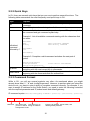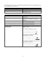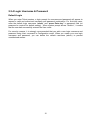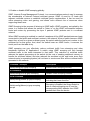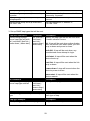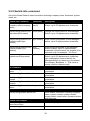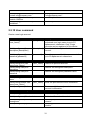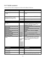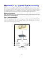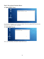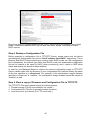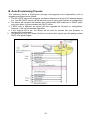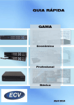
1
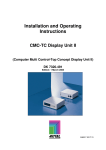
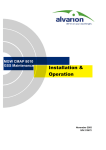
HET-3105-PLUS SERIES Gigabit Ethernet 4-Port 10/100/1000Base-T with 1Port 1000Base-X or 100/1000Base-X Uplink Managed CPE Switch Network Management User’s Manual Version 0.91 1 Trademarks CTS is a registered trademark of Connection Technology Systems Inc. Contents subject to revise without prior notice. All other trademarks remain the property of their owners. Copyright Statement Copyright Connection Technology Systems Inc. This publication may not be reproduced as a whole or in part, in any way whatsoever unless prior consent has been obtained from Connection Technology Systems Inc. FCC Warning This equipment has been tested and found to comply with the limits for a Class A digital device, pursuant to Part 15 of the FCC Rules. These limitations are designed to provide reasonable protection against harmful interference in a residential installation. This equipment generates uses and can radiate radio frequency energy and, if no installed and used in accordance with the instructions, may cause harmful interference to radio communications. However, there is no guarantee that interference will not occur in a particular installation. If this equipment does cause harmful interference to radio or television reception, which can be determined by turning the equipment off and on, the user is encouraged to try to correct the interference by one or more of the following measures: Reorient or relocate the receiving antenna. Increase the separation between the equipment and receiver. Connect the equipment into a different outlet from that the receiver is connected. Consult your local distributors or an experienced radio/TV technician for help. Shielded interface cables must be used in order to comply with emission limits. Changes or modifications to the equipment, which are not approved by the party responsible for compliance, could affect the user’s authority to operate the equipment. Copyright © 2010 All Rights Reserved. Company has an on-going policy of upgrading its products and it may be possible that information in this document is not up-to-date. Please check with your local distributors for the latest information. No part of this document can be copied or reproduced in any form without written consent from the company. Trademarks: All trade names and trademarks are the properties of their respective companies. 2 Table of Content 1. INTRODUCTION ............................................................................................................... 5 1.1 Interfaces ..................................................................................................................... 5 1.2 Management Preparations ........................................................................................... 6 1.3 LED Definitions............................................................................................................. 7 2. Command Line Interface (CLI) ........................................................................................ 8 2.1 Remote Console Management-Telnet .......................................................................... 8 2.2 Navigating CLI .............................................................................................................. 9 2.2.1 General Commands ............................................................................................... 9 2.2.2 Quick Keys........................................................................................................... 10 2.2.3 Command Format ................................................................................................ 10 2.2.4 Login Username & Password .............................................................................. 12 2.3 User Mode .................................................................................................................. 13 2.3.1 Ping command ..................................................................................................... 13 2.4 Privileged mode.......................................................................................................... 14 2.4.1 Copy-cfg command.............................................................................................. 14 2.4.2 Firmware command ............................................................................................. 15 2.4.3 Ping command ..................................................................................................... 16 2.4.4 Reload command ................................................................................................. 16 2.4.5 Write command .................................................................................................... 16 2.4.6 Configure command ............................................................................................ 16 2.5 Configuration mode .................................................................................................... 17 2.5.1 Entering Interface Numbers ................................................................................. 17 2.5.2 No command ....................................................................................................... 18 2.5.3 Show command ................................................................................................... 18 2.5.4 Interface command .............................................................................................. 20 2.5.5 IP command......................................................................................................... 21 2.5.6 MAC command .................................................................................................... 23 2.5.7 QoS command ..................................................................................................... 24 2.5.8 SNMP-Server command ...................................................................................... 27 2.5.9 Switch-info command .......................................................................................... 30 2.5.10 User command .................................................................................................. 31 2.5.11 VLAN command ................................................................................................. 32 3 2.5.12 Show sfp command ........................................................................................ 34 APPENDIX A: Set Up DHCP Auto-Provisioning ............................................................... 35 4 1. INTRODUCTION Thank you for using the 4-Port 10/100/1000 Base-T plus 1-Port 1000 Base-X or 100/100 Base-T Fast Ethernet Smart Switch. The built-in management module allows users to configure this Smart Switch and monitor the operation status locally or remotely through network. The Smart Switch is fully compliant with IEEE 802.3 and 802.3u standards. By employing store and forward switching mechanism, the Smart Switch provides low latency and faster data transmission. Moreover, it also supports more advanced functions such as QoS, VLAN, IGMP Snooping, etc. Users can configure the required settings of the Smart Switch and monitor its real-time operational status via Command Line Interface (CLI). For detailed descriptions on CLI, please refer to Section 2. 1.1 Interfaces Figure 1 below displays the interface with four 10/100/1000Mbps LAN ports. Figure 1. Four 10/100/1000 LAN Ports Figure 2 below shows the top panel of the Smart Switch that displays LED indicators for each LAN connection and link status. Figure 2. Top Panel with LED Indicators 5 1.2 Management Preparations The Smart Switch can be accessed through Telnet connection. Before you can access the Smart Switch to configure it, you need to connect cables properly. Connecting the Smart Switch It is extremely important that proper cables are used with correct pin arrangements when connecting Smart Switch to other devices such as switches, hubs, workstations, etc. 1000Base-X / 100Base-FX SFP Port The small form-factor pluggable (SFP) is a compact optical transceiver used in optical data communications applications. It interfaces with a network device mother board (for a switch, router or similar device) to a fiber optic or unshielded twisted pair networking cable. It is a popular industry format supported by several fiber optic component vendors. SFP transceivers are available with a variety of different transmitter and receiver types, allowing users to select the appropriate transceiver for each link to provide the required optical reach over the available optical fiber type. SFP transceivers are also available with a "copper" cable interface, allowing a host device designed primarily for optical fiber communications to also communicate over unshielded twisted pair networking cable. SFP slot for 3.3V mini GBIC module supports hot swappable SFP fiber transceiver. Before connecting other switches, workstation or media converter, make sure both sides of the SFP transfer are with the same media type, for example, 1000Base-SX to 1000Base-SX, 1000Bas-LX to 1000Base-LX. In addition to that, check the fiberoptic cable type match the SFP transfer model. To connect to 1000Base-SX transceiver, use the multi-mode fiber cable that one side must be male duplex LC connector type. To connect to 1000Base-LX transfer, use the single-mode fiber cable that one side must be male duplex LC connector type. 1000Base-X Fiber Port 1000Base-X Fiber port is located inside the Smart Switch. This port is primarily used for up-link connection and will always operate at 1000M / Full Duplex mode. Duplex SC or WDM Simplex SC types of connectors are available. Use proper multimode or single-mode optical fiber to connect this port with other Gigabit Ethernet Fiber port. Before connect the other switches, workstation or Media Converter, make sure both side of the fiber transfer are with the same media type, for example: 1000Base-SX to 1000Base-SX, 1000Bas-LX to 1000Base-LX. And check the fiber-optic cable type match the fiber transfer model. To connect to 1000Base-SX transfer, use the multimode fiber cable- with one side must be male duplex SC connector type. To connect to 1000Base-LX transfer, use the single-mode fiber cable-with one side must be male duplex SC connector type. 6 10/100/1000Base-T RJ-45 Auto-MDI/MDIX Port Four 10/100/1000Base-T RJ-45 Auto-MDI/MDIX ports are located in front panel of the Smart Switch. These RJ-45 ports allow users to connect their traditional copperbased Ethernet/Fast Ethernet devices to the network and support auto-negotiation and MDI/MDIX auto-crossover. In other words, either crossover or straight through CAT-5E UTP or STP cable may be used. Assigning IP Addresses IP addresses have the format n.n.n.n, for example 168.168.8.100. IP addresses are made up of two parts: The first part (168.168.XXX.XXX in the example) refers as network address identifies the network on which the device resides. Network addresses are assigned by three allocation organizations. Depending on your location, each allocation organization assigns a globally unique network number to each network that wishes to connect to the Internet. The second part (XXX.XXX.8.100 in the example) identifies the device within the network. Assigning unique device numbers is your responsibility. If you are unsure of the IP addresses allocated to you, consult the allocation organization from which your IP addresses were obtained. Remember that no two devices on a network can have the same address. If you connect to the outside, you must change all the arbitrary IP addresses to comply with those you have been allocated by the allocation organization. If you do not do this, your outside communications will not operate. A subnet mask is a filtering system for IP addresses. It allows you to further subdivide your network. You must use the proper subnet mask for proper operation of a network with subnets defined. 1.3 LED Definitions LED Power Status WAN Color Off Green Green Off Green Orange Off LAN1~LAN4 Green Orange Operation System is power down. System is power up. System is working normally. Fiber link is down. Fiber link is up and works in 100Mbps. Blinking when traffic is present. Fiber link is up and works in 1000Mbps. Blinking when traffic is present. LAN port link is down. LAN port link is up and works in 100Mbps. Blinking when traffic is present. LAN port link is up and works in 1000Mbps. Blinking when traffic is present. 7 2. Command Line Interface (CLI) This chapter introduces you how to use Command Line Interface (CLI) via Telnet connection, specifically in: Configuring the system Resetting the system Upgrading newly released firmware 2.1 Remote Console Management-Telnet You can use Command Line Interface to manage the Smart Switch via Telnet session. For first-time users, you must first assign a unique IP address to the Smart Switch before you can manage it remotely. Use any one of the RJ-45 ports on the front panel as the temporary management console port to login to the Smart Switch with the default username & password and then assign the IP address using IP command in Global Configuration mode. Follow steps described below to access the Smart Switch through Telnet session: Step 1. Use any one of the RJ-45 ports as a temporary management console port to login to the Smart Switch. Step 2. Run Telnet client and connect to 192.168.0.1. For first-time users, make sure the IP address of your PC or workstation is assigned to an IP address between 192.168.0.2 and 192.168.0.254 with subnet mask 255.255.255.0. Step 3. When asked for a username, enter “admin”. When asked for a password, leave the password field blank and press Enter (by default, no password is required.) Step 5. If you enter CLI successfully, the prompt display Switch> (the model name of your device together with a greater than sign) will appear on the screen. Step 6. Set up the Smart Switch’s IP address, subnet mask and the default gateway using “IP” command in Global Configuration mode. (See Section 2.5.5 IP command for detailed descriptions on assigning IP address to the Smart Switch.) Step 7. Once you enter the new IP address for the Smart Switch, the telnet session will be terminated immediately. Use your new IP address to login to the Smart Switch via Telnet session. Limitation: Only one active Telnet session can access the Smart Switch at a time. 8 2.2 Navigating CLI When you successfully access the Smart Switch, you will be asked for a login username. Enter your authorized username and password, and then you will be directed to User mode. In CLI management, the User mode only provides users basic functions to operate the Smart Switch. If you would like to configure advanced features of the Smart Switch, such as, VLAN, QoS, you must enter the Configuration mode. The following table provides an overview of modes available in this Smart Switch. Command Mode User mode Privileged mode Configuration mode Access Method Login username & password From user mode, enter the enable command From the enable mode, enter the config or configure command Prompt Displayed Exit Method Switch> logout Switch# disable, exit, logout Switch(config)# exit NOTE: By default, the model name will be used for the prompt display. You can change the prompt display to the one that is ideal for your network environment using the hostname command. However, for convenience, the prompt display “Switch” will be used throughout this user’s manual. 2.2.1 General Commands This section introduces you some general commands that you can use in User, Enable, and Configuration mode, including “help”, “exit”, “history” and “logout”. Entering the command… To do this… Switch> help Switch# help Switch(config)# help Obtain a list of available commands in the current mode. Switch> exit Switch# exit Switch(config)# exit Return to the previous mode or login screen. Switch> history Switch# history Switch(config)# history List all commands that have been used. Switch> logout Switch# logut Logout from the CLI or terminate Telnet session. 9 Available Modes User Mode Privileged Mode Configuration Mode User Mode Privileged Mode Configuration Mode User Mode Privileged Mode Configuration Mode User Mode Privileged Mode 2.2.2 Quick Keys In CLI, there are several quick keys that you can use to perform several functions. The following table summarizes the most frequently used quick keys in CLI. Keys tab ? Purpose Enter an unfinished command and press “Tab” key to complete the command. Press “?” key in each mode to get available commands. Enter an unfinished command or keyword and press “?” key to complete the command and get command syntax help. Example 1: List all available commands starting with the characters that you enter. unfinished command followed by ? Switch#h? help history Show available commands Show history commands Switch#he? <cr> Switch#help Example 2: Complete a valid command and show the next part of syntax. Switch(config)#sec? storm-protection Switch(config)#security Up arrow Down arrow Storm control subcommands Use Up arrow key to scroll through the previous entered commands, beginning with the most recent key-in commands. Use Down arrow key to scroll through the previous entered commands, beginning with the commands that are entered first. 2.2.3 Command Format While in CLI, you will see several symbols very often. As mentioned above, you might already know what “>”, “#” and (config)# represent. However, to perform what you intend the device to do, you have to enter a string of complete command correctly. For example, if you want to assign IP address for the Smart Switch, you need to enter the following command with the required parameter and IP, subnet mask and default gateway: IP command syntax: Switch(config)#ip address [A.B.C.D] [255.X.X.X] [A.B.C.D] Switch(config)#ip address 192.168.1.198 255.255.255.255 192.168.1.254 Hostname This means that This allows you to you are in Global assign IP address. Configuration mode Enter the IP address, subnet mask, and default gateway address. 10 The following table lists common symbols and syntax that you will see very frequently in this User’s Manual for your reference: Symbols > # (config)# Brief Description Currently, the device is in User mode. Currently, the device is in Privileged mode. Currently, the device is in Global Configuration mode. Syntax [ ] Brief Description Brackets mean that this field is required information. Brackets represent that this is a required field. Enter an IP address or gateway address. Brackets represent that this is a required field. Enter the subnet mask. There are three options that you can choose. Specify one of them. Specify a value between 1 and 8191. Specify one value, more than one value or a range of values. [A.B.C.D ] [255.X.X.X] [port-based | 802.1p | dscp] [1-8191] [0-7] 802.1p_list [0-63] dscp_list For example: specifying one value Switch(config)#qos 802.1p-map 1 0 Switch(config)#qos dscp-map 10 3 For example: specifying three values (separating by a comma) Switch(config)#qos 802.1p-map 1,3 0 Switch(config)#qos dscp-map 10,13,15 3 For example: specifying a range of values (separating by a hyphen) Switch(config)#qos 802.1p-map 1-3 0 Switch(config)#qos dscp-map 10-15 3 11 2.2.4 Login Username & Password Default Login When you enter Telnet session, a login prompt for username and password will appear to request a valid and authorized username and password combination. For first-time users, enter the default login username “admin” and “press Enter key” in password field (no password is required for default setting). When system prompt shows “Switch>”, it means that the user has successfully entered the User mode. For security reasons, it is strongly recommended that you add a new login username and password using User command in Configuration mode. When you create your own login username and password, you can delete the default username (admin) to prevent unauthorized access. 12 2.3 User Mode In User mode, only a limited set of commands are provided. Please note that in Use mode, you have no authority to configure advanced settings. You need to enter Enable mode and Configuration mode to set up advanced functions of a switch feature. For a list of commands available in User mode, enter the question mark (?) or “help” command after the system prompt display Switch>. Command exit help history logout enable ping Description Quit the User mode or close the terminal connection. Display a list of available commands in User mode. Display the command history. Logout from the Smart Switch. Enter the Privileged mode. Ping a remote host. 2.3.1 Ping command Ping is used to test the connectivity of end devices and also can be used to self test the network interface card. Enter the ping command in User mode. In this command, you can add an optional packet size value and an optional value for the number of times that packets are sent and received. Command Switch> ping [A.B.C.D] [-s size] [r repeat] [-t timeout] Parameter [A.B.C.D] [-s size] [-r repeat] [-t timeout] Description Enter the IP address that you would like to ping. Enter the packet size that would be sent. The allowable packet size is from 8 to 4000 bytes. The parameter is optional. Enter the number of times that ping packets are sent. The allowable repeat number is from 1 to 99. The parameter is optional. Enter the timeout value when the specified IP address is not reachable. The parameter is optional. Example Switch> ping 127.0.0.1 Switch> ping 127.0.0.1 –s 128 –r 5 –t 10 13 2.4 Privileged mode The only place where you can enter the Privileged (Enable) mode is in User mode. When you successfully enter Enable mode, the prompt will be changed to Switch# (the model name of your device together with a pound sign). Enter the question mark (?) or help command to view a list of commands available for use. Command copy-cfg configure disable exit firmware help history logout reload write show ping Description Restore or backup configuration file via FTP or TFTP server. Enter Global Configuration mode. Exit Enable mode and return to User Mode. Exit Enable mode and return to User Mode. Upgrade firmware via FTP or TFTP. Display a list of available commands in Enable mode. Show commands that have been used. Logout from the Managed Switch. Restart the Managed Switch. Save your configurations to Flash. Show a list of commands or show the current setting of each listed command. Ping a remote host. 2.4.1 Copy-cfg command Use “copy-cfg” command to backup a configuration file via FTP or TFTP server or restore the Smart Switch back to the defaults or to the defaults but keep IP configurations. 1. Restore a configuration file via FTP or TFTP server. Command Parameter Description Switch# copy-cfg [A.B.C.D] Enter the IP address of your FTP server. from ftp [A.B.C.D] [file_name] Enter the configuration file name that you [file_name] want to restore. [user_name] [user_name] Enter the username for your FTP server. [password] [password] Enter the password for your FTP server. Switch# copy-cfg [A.B.C.D] Enter the IP address of your TFTP server. from tftp [A.B.C.D] [file_name] Enter the configuration file name that you [file_name] want to restore. Example Switch# copy-cfg from ftp 192.168.1.198 HS_0600_file.conf misabcxyz 135780 Switch# copy-cfg from tftp 192.168.1.198 HS_0600_file.conf 2. Restore the Smart Switch back to default settings. Command / Example Switch# copy-cfg from default 14 3. Restore the Smart Switch back to default settings but keep IP configurations. Command / Example Switch# copy-cfg from default keep-ip 4. Backup a configuration file to FTP or TFTP server. Command Parameter Description Switch# copy-cfg to [A.B.C.D] Enter the IP address of your FTP server. ftp [A.B.C.D] [file_name] Enter the configuration file name that you want to [file_name] backup. [user_name] [user_name] Enter the username for your FTP server. [password] [password] Enter the password for your FTP server. Switch# copy-cfg to [A.B.C.D] Enter the IP address of your TFTP server. tftp [A.B.C.D] [file [file name] Enter the configuration file name that you want to name] backup. Example Switch# copy-cfg to ftp 192.168.1.198 HS_0600_file.conf misabcxyz 135780 Switch# copy-cfg to tftp 192.168.1.198 HS_0600_file.conf 2.4.2 Firmware command To upgrade Firmware via FTP or TFTP server. Command Switch# firmware upgrade ftp [A.B.C.D] [file_name] [user_name] [password] Switch# firmware upgrade tftp [A.B.C.D] [file_name] Parameter [A.B.C.D] [file name] [user_name] Description Enter the IP address of your FTP server. Enter the firmware file name that you want to upgrade. Enter the username for FTP server login. [password] Enter the password for FTP server login. [A.B.C.D] Enter the IP address of your TFTP server. [file_name] Enter the firmware file name that you want to upgrade. Example Switch# firmware upgrade ftp 192.168.1.198 HS_0600_file.bin edgeswitch10 abcxyz Switch# firmware upgrade tftp 192.168.1.198 HS_0600_file.bin 15 2.4.3 Ping command Command Switch# ping [A.B.C.D] [-s size] [r repeat] [-t timeout] Parameter [A.B.C.D] [-s size] [-r repeat] [-t timeout] Description Enter the IP address that you would like to ping. Enter the packet size that would be sent. The allowable packet size is from 8 to 4000 bytes. The parameter is optional. Enter the number of times that ping packets are sent. The allowable repeat number is from 1 to 99. The parameter is optional. Enter the timeout value when the specified IP address is not reachable. The parameter is optional. Example Switch# ping 127.0.0.1 –s 128 –r 5 –t 10 2.4.4 Reload command To restart the Smart Switch, enter the reload command. Command / Example Switch# reload 2.4.5 Write command To save running configurations to startup configurations, enter the write command. All unsaved configurations will be lost when you restart the Smart Switch. Command / Example Switch# write 2.4.6 Configure command The only place where you can enter Global Configuration mode is in Privileged mode. You can type in “configure” or “config” for short to enter Global Configuration mode. The display prompt will change from “Switch#” to “Switch(config)#” once you successfully enter Global Configuration mode. Command / Example Switch#config Switch(config)# Switch#configure Switch(config)# 16 2.5 Configuration mode When you enter “configure” or “config” and press “Enter” in Privileged mode, you will be directed to Global Configuration mode where you can set up advanced switching functions, such as QoS, VLAN and storm control security globally. Any commands entered will apply to running-configuration and the device’s operation. From this level, you can also enter different sub-configuration modes to set up specific configurations for VLAN, QoS, security or interfaces. Command exit help history ip mac qos snmp-server switch-info user vlan no interface show Description Exit the configuration mode. Display a list of available commands in Configuration mode. Show commands that have been used. Set up the IP address and enable DHCP mode & IGMP snooping. Set up each port’s MAC learning function. Set up the priority of packets, DSCP mapping. Create a new SNMP community and trap destination and specify the trap types. Set up acceptable frame size and address learning, etc. Create a new user account. Set up VLAN mode and VLAN configuration. Disable a command or set it back to its default setting. Select a single interface or a range of interfaces. Show a list of commands or show the current setting of each listed command. 2.5.1 Entering Interface Numbers In the Global Configuration mode, you can configure a command that only apply to interfaces specified. For example, you can set up each interface’s VLAN assignment, speeds, or duplex modes. To configure, you must first enter the interface number. There are four ways to enter your interface numbers to signify the combination of different interfaces that apply to a command or commands. Commands Switch(config)# interface 1 Switch(config-if)# Switch(config)# interface 1,3 Switch(config-if)# Switch(config)#interface 1-3 Switch(config-if)# Switch(config)#interface 1,3-4 Switch(config-if)# Description Enter a single interface. Only interface 1 will apply to commands entered. Enter three discontinuous interfaces, separating by a comma. Interface 1, 3 will apply to commands entered. Enter three continuous interfaces. Use a hyphen to signify a range of interface numbers. In this example, interface 1, 2, and 3 will apply to commands entered. Enter a single interface number together with a range of interface numbers. Use both comma and hyphen to signify the combination of different interface numbers. In this example, interface 1, 3, 4 will apply to commands entered. 17 The “interface” command can be used together with “QoS” and “VLAN” commands. For detailed usages, please refer to QoS and VLAN section below. 2.5.2 No command Almost commands that you enter in Configuration mode can be negated using “no” command followed by the same or original command. The purpose of “no” command is to disable a function, remove a command, or set the setting back to the default value. In each sub-section below, the use of no command to fulfill different purposes will be introduced. 2.5.3 Show command “show” command is very important for network administrators to get information about the device, receive outputs to verify a command’s configurations or troubleshoot a network configuration error. “Show” command can be either used in Privileged or Configuration mode. The following describes different uses of “show” command. 1. Display system information Enter “show switch-info” command in Privileged or Configuration mode, then the following similar screen page will appear. Company Name: Display a company name for this Smart Switch. Use “switch-info company-name [company-name]” command to edit this field. System Object ID: Display the predefined System OID. System Contact: Display contact information for this Smart switch. Use “switch-info syscontact [sys-contact]” command to edit this field. System Name: Display a descriptive system name for this Smart Switch. Use “switch-info sys-name [sys-name]” command to edit this field. 18 System Location: Display a brief location description for this Smart Switch. Use “switchinfo sys-location [sys-location]” command to edit this field. Model Name: Display the product’s model name. Firmware Version: Display the firmware version used in this device. M/B Version: Display the main board version. Fiber Type: Display information about the slide-in or fixed fiber type. Fiber Wavelength: Display the slide-in or fixed fiber’s TX and RX wavelength information. Serial Number: Display the serial number of this Smart Switch. Date Code: Display the Smart Switch Firmware date code. 2. Display or verify currently-configured settings Refer to “Interface command”, “QoS command” and “VLAN command” sections. 19 2.5.4 Interface command Use this command to set up various port configurations of discontinuous or a range of ports. Command Switch(config)# interface [port_list] Parameter Description [port_list] Enter several port numbers separating by a comma or a range of port numbers. For example: 1,3 or 2-4 Switch(config-if)# speed [1000 | 100 |10 | auto-sense] [1000 | 100 |10 | autosense] Switch(config-if)# autonegotiation Switch(config-if)# duplex [full] [full] Switch(config-if)# flowcontrol Switch(config-if)# shutdown No command Switch(config-if)# no autonegotiation Switch(config-if)# no duplex Set up the selected interfaces’ speed. “auto-sense” option is used for fiber port only. This option allows the Smart Switch to automatically detect fiber speed of the connected device. Set the selected interfaces’ to autonegotiation. When auto-negotiation is enabled, speed configuration will be ignored. Set the selected interfaces’ to full duplex mode. Enable the selected interfaces’ flow control function. Administratively disable the selected ports’ status. Set auto-negotiation setting to the default setting. Set the selected ports’ duplex mode to the default setting. Set the selected ports’ flow control function to the default setting. Administratively enable the selected ports’ status. Set the selected ports’ speed to the default setting. Switch(config-if)# no flowcontrol Switch(config-if)# no shutdown Switch(config-if)# no speed Show command Switch(config)# show interface Show each interface’s port configurations. Switch(config)# show interface [port_list] Switch(config)# show interface status [port_list] Switch(config)# show interface status [port_list] [port_list] 20 Show the specified interfaces’ port configurations. Show each interface’s port status including media type, forwarding state, speed, duplex mode, flow control and link up/down status. Show the specified interface’s port status including media type, forwarding state, speed, duplex mode, flow control and link up/down status. Interface command example Switch(config)# interface 1-3 Enter port 1 to port 3’s interface mode. Switch(config-if)# auto-negotiation Set the selected interfaces’ to autonegotiation. Set the selected interfaces’ to full duplex mode. Enable the selected interfaces’ flow control function. Set the selected ports’ speed to 100Mbps. Switch(config-if)# duplex full Switch(config-if)# flowcontrol Switch(config-if)# speed 100 Switch(config-if)# shutdown Administratively disable the selected ports’ status. 2.5.5 IP command 1. Set up or remove the IP address of the Smart Switch. IP command Parameter Switch(config)#ip [A.B.C.D] address [A.B.C.D] [255.X.X.X] [255.X.X.X] [A.B.C.D] [A.B.C.D] No command Switch(config)# no ip address Show command Switch(config)# show ip address IP command example Switch(config)# ip address 192.168.1.198 255.255.255.0 192.168.1.254 Description Enter the desired IP address for your Smart Switch. Enter subnet mask of your IP address. Enter the default gateway address. Remove the Smart Switch’s IP address. Show the current IP configurations or verify the configured IP settings. Set up the Smart Switch’s IP to 192.168.1.198, subnet mask to 255.255.255.0, and default gateway to 192.168.1.254. 2. Enable the Smart Switch to automatically get IP address from the DHCP server. Command / Example Description Switch(config)# ip address dhcp Enable DHCP mode. No command Switch(config)# no ip address dhcp Disable DHCP mode. Show command Switch(config)# show ip address Show the current IP configurations or verify the configured IP settings. 21 3. Enable or disable IGMP snooping globally. IGMP, Internet Group Management Protocol, is a communications protocol used to manage the membership of Internet Protocol multicast groups. IGMP is used by IP hosts and adjacent multicast routers to establish multicast group memberships. It can be used for online streaming video and gaming, and allows more efficient use of resources when supporting these uses. IGMP Snooping is the process of listening to IGMP traffic. IGMP snooping, as implied by the name, is a feature that allows the switch to "listen in" on the IGMP conversation between hosts and routers by processing the layer 3 packets IGMP packets sent in a multicast network. When IGMP snooping is enabled in a switch it analyses all the IGMP packets between hosts connected to the switch and multicast routers in the network. When a switch hears an IGMP report from a host for a given multicast group, the switch adds the host's port number to the multicast list for that group. And, when the switch hears an IGMP Leave, it removes the host's port from the table entry. IGMP snooping can very effectively reduce multicast traffic from streaming and other bandwidth intensive IP applications. A switch using IGMP snooping will only forward multicast traffic to the hosts interested in that traffic. This reduction of multicast traffic reduces the packet processing at the switch (at the cost of needing additional memory to handle the multicast tables) and also reduces the workload at the end hosts since their network cards (or operating system) will not have to receive and filter all the multicast traffic generated in the network. Command / Example Description Switch(config)# ip igmp snooping Enable IGMP snooping function. No command Switch(config)# no ip igmp snooping Disable IGMP snooping function. Show command Switch(config)# show ip igmp snooping Switch(config)#show ip igmp snooping groups Show current IGMP snooping status including fast leave function. Show IGMP group table. When IGMP Snooping is enabled, the Smart Switch is able to read multicast group IP and the corresponding MAC address from IGMP packets that enter the device. 22 4. Enable IGMP snooping fast-leave function. This works only when IGMP Snooping is enabled. When Fast Leave is enabled, the Smart Switch immediately removes the port when it detects IGMPv1 & IGMPv2 leave message on that port. Command / Example Switch(config)# ip igmp snooping immediate-leave No command Switch(config)# no ip igmp snooping immediate-leave Show command Description Enable IGMP fast leave function. Description Disable IGMP fast leave function. Description Show current IGMP snooping status including fast leave function. Switch(config)# show ip igmp snooping Switch(config)# show ip igmp snooping groups Show IGMP group table. 2.5.6 MAC command Set up MAC address table aging time. Entries in the MAC address table containing source MAC addresses and their associated ports will be deleted if they are not accessed within aging time. MAC Command Switch(config)# mac addresstable aging-time [0-458745] Parameter Description [0-458745] Enter the aging time for MAC addresses in seconds. No command Switch(config)# no mac address-table agingtime Show command Switch(config)# show mac aging-time MAC command example Switch(config)# mac address-table agingtime 200 Description Set MAC address table aging time to the default value (300 seconds). Description Show current MAC address table aging time or verify currently configured aging time. Description Set MAC address aging time to 200 seconds. 23 2.5.7 QoS command 1. Specify the desired QoS mode. QoS command Switch(config)#qos [portbased | 802.1p | dscp] Parameter [port-based | 802.1p | dscp] Description Specify one QoS mode. port-based: Use “interface” and “qos default-class” command to assign a queue to the selected interfaces. 802.1p: Use “802.1p-map [0-7] 802.1p_list [0-3]” command to assign priority bits to a queue. No command Switch(config)# no qos dscp: Use “dscp-map [0-63] dscp_list [03]” to assign several DSCP values to a queue. Description Disable QoS function. Show command Switch(config)# show qos Description Show or verify QoS configurations. QoS command example Switch(config)# qos 802.1p Enable QoS function and use 802.1p mode. Enable QoS function and use DSCP mode. Enable QoS function and use Port-Based mode. Switch(config)# qos dscp Switch(config)# qos port-based 2. Set up the DSCP and queue mapping. DSCP-map command Switch(config)# qos dscp-map [063] dscp_list [03] Parameter Description [0-63] dscp_list Specify the corresponding DSCP value or values that you want to map to a priority queue value. [0-3] Set up the corresponding queue. No command Switch(config)# no qos Disable QoS function Show command Switch(config)# show qos Show or verify QoS configurations. 24 DSCP-map example Switch(config)# qos dscp-map 10-50 3 Mapping DSCP values from 10 to 50 to queue 3. 3. Set up QoS queuing mode. Queuing-mode command Switch(config)# qos queuingmode [weight] Parameter Description [weight] By default, “weight” queuing mode is used. If you want to use “strict” queuing mode, you need to disable “weight” queuing mode. Weight mode: This mode enables users to assign different weights (0 to 49) to 4 queues. Strict mode: This indicates that services to each egress queues are offered depending on the maximum rate (1000Mbps). No command Switch(config)# no qos queuing-mode Set the queuing mode to Strict mode. Show command Switch(config)# show qos Show or verify QoS configurations. Queuing-mode example Switch(config)# qos queuing-mode weight Change the queuing mode from strict to weight. 4. Set up queuing weight. Queue-weighted command Switch(config)# qos queueweighted [1:2:4:8] Parameter Description [1:2:4:8] By default, schedule weight for Q0, Q1, Q2, Q3 is “1:1:1:1”. Use “qos queueweighted 1:2:4:8” to change each queue’s weight to the corresponding one. The weight value can be assigned to each queue is between 0 and 49. No command Switch(config)# no qos queue-weighted Change queue weight to 1:1:1:1. Show command Switch(config)# show qos Show or verify QoS configurations. 25 Queuing-mode example Switch(config)# qos queue-weighted 1:2:4:8 Change queue weight to 1:2:4:8. 5. Assign a tag priority to the specific queue. 802.1p-map command Switch(config)# qos 802.1pmap [0-7] 802.1p_list [0-3] No command Switch(config)# no qos 802.1p-map [0-7] 802.1p_list Parameter [0-7] 802.1p_list Description Assign a 802.1p priority bit or several 802.1p priority bits for mapping. [0-3] Assign a 802.1p queue value for mapping. [0-7] 802.1p_list Assign a 802.1p priority bit or several 802.1p priority bits that you want to delete or remove. Show command Switch(config)# show qos Show or verify QoS configurations. 802.1p-map example Switch(config)# qos 802.1p-map 6-7 3 Map priority bit 6 and 7 to queue 3. 6. Use interface command to set up default class for the selected interfaces. QoS & Interface command Switch(config-if)# qos defaultclass [0-3] Parameter [0-3] No command Switch(config-if)# no qos default-class Show command Switch(config)#show qos QoS & Interface example Switch(config)# interface 1-3 Switch(config-if)# qos default-class 3 Description Specify the selected interfaces’ default queue. Description Set QoS default class setting back to defaults. Description Show or verify QoS configurations. Description Enter several discontinuous port numbers separating by a comma or a range of ports with a hyphen. For example:1,3 or 2-4 Set the selected ports’ default class to 3. 26 2.5.8 SNMP-Server command 1. Create a SNMP community and set up detailed configurations for this community. Snmp-server command Switch(config)# snmpserver community [community] Switch(config-snmpserver)# active Switch(config-snmpserver)# description [Description] Parameter [community] Description Specify a SNMP community name of up to 20 alphanumeric characters. Enable this SNMP community account. [Description] Switch(config-snmp[admin | rw | server)#level [admin | rw | ro ro | | access_denied] access_deni ed] Enter the description for this SNMP community of up to 35 alphanumerical characters. Specify the access privilege for this SNMP account. admin: Full access right includes maintaining user account, system information, loading factory settings, etc. rw: Read & Write access privilege. Full access right but cannot modify user account, system information and load factory settings. ro: Read Only access privilege. Allow to view only. access_denied: Completely forbidden for access. No command Switch(config)# no snmp-server community mycomm Switch(config-snmp-server)# no active Switch(config-snmp-server)# no description Switch(config-snmp-server)# no level Show command Switch(config)# show snmp-server community mycomm Switch(config-snmp-server)# show Delete the community “mycomm”. Disable this SNMP community account. In this example “mycomm” community is disabled. Remove the entered SNMP community descriptions for “mycomm”. Remove the configured level. This will set this community’s level to access_denied. Show SNMP community account’s information in Global Configuration mode. View or verify the configured SNMP community account’s information. 27 Exit command Switch(config-snmp-server)#exit Return to Global Configuration mode. Snmp-server example Switch(config)# snmp-server community mycomm Switch(config-snmp-server)# active Create a new community “mycomm” and edit the details of this community account. Activate the SNMP community “mycomm”. Switch(config-snmp-server)# description rddeptcomm Switch(config-snmp-server)# level admin Add a description for “mycomm” community. Set “mycomm” community level to admin. 2. Set up a SNMP trap destination. Trap-dest command Parameter Switch(config)#snmp[1] server trap-destination [1] Switch(config-snmpserver)# active Switch(config-snmp[community] server)# community [community] Switch(config-snmp[A.B.C.D] server)# destination [A.B.C.D] No command Switch(config)# no snmp-server trap-dest 1 Switch(config-snmp-server)# no active Description Create a trap destination account. Switch(config-snmp-server)# no community Switch(config-snmp-server)# no description Delete the configured community name. Show command Switch(config)# show snmp-server trapdest Switch(config)# show snmp-server trapdest 1 Exit command Switch(config-snmp-server)# exit Description Show SNMP trap destination information. Trap-dest example Switch(config)# snmp-server trap-dest 1 Description Create a trap destination account. Enable this SNMP trap destination account. Enter the community name of network management system. Enter the trap destination IP address for this trap destination account. Description Delete a trap destination account. Disable this SNMP trap destination account. Delete the configured trap destination description. Show the specified SNMP trap destination information. Description Return to Global Configuration mode. 28 Switch(config-snmp-server)# active Activate the trap destination account. Switch(config-snmp-server)# community mycomm Switch(config-snmp-server)# description redepttrapdest Switch(config-snmp-server)# destination 192.168.1.254 Refer this trap destination account to the community “mycomm”. Add a description for this trap destination account. Set trap destination IP address to 192.168.1.254. 3. Set up SNMP trap types that will be sent. Trap-type command Switch(config)# snmpserver trap-type [all |authfail | cold-start | port-link | power-down | warm-start] Parameter [all |auth-fail | cold-start | port-link | power-down | warm-start] Description Specify the trap type that will be sent when a certain situation occurs. all: A trap will be sent when authentication fails, the device cold /warm starts, port link is up or down and power is down. auth-fail: A trap will be sent when any unauthorized users attempt to login. cold-start: A trap will be sent when the device boots up. port-link: A trap will be sent when the link is up or down. power-down: A trap will be sent when the device’s power is down. No command Switch(config)# no snmpserver trap-type auth-fail all |auth-fail | cold-start | port-link | power-down | warm-start] warm-start: A trap will be sent when the device restarts. Description Specify the trap type that will not be sent. Show command Switch(config)# show snmp-server traptype Description Show the current enable/disable status of each type of trap. Trap-type example Switch(config)# snmp-server trap-type all Description All types of SNMP traps will be sent. 29 2.5.9 Switch-info command Set up the Smart Switch’s basic information including company name, hostname, system name, etc. Switch-info Command Switch(config)# switch-info company-name [companyname] Parameter [companyname] Description Enter a company name for this Smart Switch, up to 55 alphanumeric characters. Switch(config)# switch-info host-name [host-name] [host-name] Change the model name for this Managed Switch, up to 15 alphanumeric characters. Switch(config)# switch-info system-contact [syscontact] [sys-contact] Enter contact information for this Managed switch, up to 55 alphanumeric characters. Switch(config)# switch-info system-location [syslocation] [syslocation] Switch(config)# switch-info system-name [sys-name] [sys-name] Enter a brief description of the Managed Switch location, up to 55 alphanumeric characters. Like the name, the location is for reference only, for example, “13th Floor”. Enter a unique name for this Managed Switch, up to 55 alphanumeric characters. Use a descriptive name to identify the Managed Switch in relation to your network, for example, “Backbone 1”. This name is mainly used for reference only. No command Switch(config)# no switch-info companyname Switch(config)# no switch-info host-name Switch(config)# no switch-info systemcontact Switch(config)# no switch-info systemlocation Switch(config)# no switch-info systemname Show command Switch(config)# show switch-info Switch-info example Switch(config)# switch-info companyname telecomxyz Switch(config)# switch-info host-name Delete the entered company name information. Delete the entered switch model name information. Delete the entered system contact information. Delete the entered system location information. Delete the entered system name information. Show switch information including company name, system contact, system location, system name, model name, firmware version and fiber type. Set the company name to “telecomxyz”. Set the switch model name to “model 1” 30 model 1 Switch(config)# switch-info systemcontact [email protected] Switch(config)# switch-info systemlocation 13thfloor Switch(config)# switch-info system-name backbone1 Set the system contact field to “[email protected]”. Set the system location field to “13thfloor”. Set the system name field to “backbone1”. 2.5.10 User command Create a new login account. User command Switch(config)# user name [user_name] Switch(config-user)# description [description] Switch(config-user)# password [password] No command Switch(config)# no user name [user_name] Switch(config-user)# no description Switch(config-user)# no password Show command Switch(config)# show user name Switch(config)# show user name [user_name] Switch(config-user)# show Parameter Description [user_name] Enter the new account’s username. The authorized user login name is up to 20 alphanumeric characters. Only 3 login accounts can be registered in this device. [description] Enter the brief description for this user account. [password] Enter the password for this user account of up to 20 alphanumeric characters. [user_name] Delete the specified account. Remove the configured description. Remove the configured password value. List all user accounts. [user_name] Show the specified account’s information. Show or verify the newly-created user account’s information. User command example Switch(config)# user name miseric Create a new login account “miseric”. Switch(config-user)# level admin Set “miseric” user level to admin. Switch(config-user)# description misengineer Switch(config-user)# password mis2256i Add a description to this new account “miseric”. Set up a password for this new account “miseric” 31 2.5.11 VLAN command Create a 802.1q VLAN, management VLAN and Port-Based VLAN rule. VLAN dot1q command Switch(config)# vlan dot1q-vlan Parameter Description Globally enable 802.1q VLAN. Switch(config)# vlan dot1q-vlan [1-4094] [1-4094] Enter a VID number to create a 802.1q VLAN. Switch(config)# vlan management-vlan [1-4094] management-port [port_list] [1-4094] Enter the management VLAN ID. [port_list] Specify the management port number. [port_list] Enter several discontinuous port numbers separating by a comma or a range of ports with a hyphen. For example:1,3 or 2-4 Set the selected ports to access mode (untagged). Set the selected ports to trunk mode (tagged). Enable native VLAN for untagged traffic. [1-4094] Set up the selected ports’ PVID. VLAN & Interface command Switch(config)# interface [port_list] Switch(config-if)# vlan dot1q-vlan mode access Switch(config-if)# vlan dot1q-vlan mode trunk Switch(config-if)# vlan dot1q-vlan mode trunk native Switch(config-if)# vlan dot1q-vlan access-vlan [1-4094] Switch(config-if)# vlan dot1q-vlan trunk-vlan [1-4094] Switch(config-if)# vlan port-based [name] No command Switch(config)# no vlan dot1qvlan Switch(config)# no vlan dot1qvlan [1-4094] Switch(config)# no vlan portbased [name] Group the selected ports to a specified VLAN. [name] Set the selected ports to a specified port-based VLAN. By default, every The names port is a member port in each portcan be based VLAN. entered are: port1vlan, port2vlan, port3vlan, port4vlan, port5vlan Description Disable 802.1q VLAN globally. [1-4094] [1-4094] Delete the VID 100. [name] Remove or delete the selected port from the specified port-based VLAN. 32 Switch(config-if)# no vlan dot1qvlan access-vlan Switch(config-if)# no vlan dot1qvlan mode Switch(config-if)#no vlan dot1qvlan mode trunk native Switch(config-if)# no vlan dot1qvlan trunk-vlan [1-4094] Switch(config-if)# no vlan portbased [name] Show command Switch(config)# show vlan Set the selected ports’ PVID to the default setting. Remove VLAN dot1q mode. [1-4094] [name] Switch(config)# show vlan dot1qvlan Switch(config)# show vlan portbased Switch(config)# show vlan interface Switch(config)# show vlan [port_list] interface [port_list] VLAN dot1q & interface example Disable native VLAN for untagged traffic. Remove the selected ports’ VLAN 100 port membership. The selected ports are no longer member ports in VLAN 100. Remove or delete the selected port from the specified port-based VLAN. Description Display global VLAN information including 802.1q VLAN Enable/Disable status and CPU VLAN ID. Show 802.1q VLAN table. Show port-based VLAN table. Show each interface’s VLAN assignment and tagging information. Show the selected ports’ VLAN assignment and tagging information. Switch(config)# vlan dot1q-vlan Enable 802.1q VLAN globally. Switch(config)# vlan dot1q-vlan 100 Switch(config)# vlan management-vlan 1 management-port 1-3 Switch(config)# interface 1-3 Create a new VLAN 100. Switch(config-if)# vlan dot1q-vlan mode access Set the selected ports to untagged. Switch(config-if)#vlan dot1q-vlan mode trunk Switch(config-if)#vlan dot1q-vlan access-vlan 100 Switch(config-if)# vlan dot1q-vlan trunk-vlan 50 Set the selected ports to tagged. Set port 1~3 to management ports. Enter port 1 to port3’s interface mode. Switch(config-if)# vlan port-based port3vlan 33 Set the selected ports’ PVID to 100. Group the selected ports to VLAN 50. Set the selected ports to “port3vlan” port-based VLAN group. 2.5.12 Show sfp command When you slide-in SFP transceiver, detailed information about this module can be viewed by issuing this command. Command Description Display SFP information including transmission speed, distance, vendor’s name, vendor’s P/N and Vendor’s S/N Display SFP information including temperature, voltage, TX Bias, TX power, RX power. Switch(config)#show sfp information Switch(config)#show sfp state 34 APPENDIX A: Set Up DHCP Auto-Provisioning Networking devices, such as switches or gateways, with DHCP Auto-provisioning function allow you to automatically upgrade firmware and configuration at startup process. Before setting up DHCP Server for auto-upgrade of firmware and configuration, please make sure the Managed Switch that you purchased can support DHCP Auto-provisioning. Setup procedures and auto-provisioning process are described below for your reference. A. Setup Procedures Follow the steps below to set up Auto Provisioning server, modify dhcpd.conf file and generate a copy of configuration file. Step 1. Setup Environment DHCP Auto-provisioning-enabled products that you purchased support the DHCP option 60 to work as a DHCP client. To make auto-provisioning function work properly, you need to prepare ISC DHCP server, File server (TFTP or FTP) and the switching device. See below for a possible network topology example. ISC DHCP Server Smart Switch TFTP Server Smart Switch Typology Example 35 Step 2. Set up Auto Provision Server Update DHCP Client Linux Fedora 12 supports “yum” function by default. First of all, update DHCP client function by issuing “yum install dhclient” command. Install DHCP Server Issue “yum install dhcp” command to install DHCP server. 36 Copy dhcpd.conf to /etc/dhcp/ directory Copy dhcpd.conf file provided by the vendor to /etc/dhcp/ directory. Please note that each vendor has their own way to define auto provisioning. Make sure to use the file provided by the vendor. Enable and run DHCP service 2 3 1 1. Choose dhcpd. 2. Enable DHCP service. 3. Start running DHCP service. NOTE: DHCP service can also be enabled using CLI. Issue “dhcpd” command to enable DHCP service. 37 Step 3. Modify dhcpd.conf file Open dhcpd.conf file in /etc/dhcp/ directory Double-click dhcpd.conf placed in /etc/dhcp/ directory to open it. Modify dhcpd.conf file The following marked areas in dhcpd.conf file can be modified with values that work with your networking environment. 38 1. Define DHCP default and maximum lease time in seconds. Default lease time: If a client does not request a specific IP lease time, the server will assign a default lease time value. Maximum lease time: This is the maximum length of time that the server will lease for. 2. Define subnet, subnet mask, IP range, broadcast address, router address and DNS server address. 3. Map a host’s MAC address to a fixed IP address. 4. Map a host’s MAC address to a fixed IP address. Use the same format to create multiple MAC-to-IP address bindings. 39 5. This value is configurable and can be defined by users. 6. Specify the protocol used (Protocol 1: FTP; Protocol 0: TFTP). 7. Specify the FTP or TFTP IP address. 8. Login TFTP server anonymously (TFTP does not require a login name and password). 9. Specify FTP Server login name and password. 10. Specify the product model name. 11. Specify the firmware filename. 12. Specify the MD5 for firmware image. 13. Specify the configuration filename. 14. Specify the MD5 for configuration file. NOTE 1: The text beginning with a pound sign (#) will be ignored by the DHCP server. For example, in the figure shown above, firmware-file-name “HS-0600-provision_2.bin” and firmware-md5 (line 5 & 6 from the bottom) will be ignored. If you want DHCP server to process these two lines, remove pound signs in the initial of each line. NOTE 2: You can use either free software program or Linux default md5sum function to get MD5 checksum for firmware image and configuration file. 40 Restart DHCP service 41 Every time when you modify dhcpd.conf file, DHCP service must be restarted. Issue “killall dhcpd” command to disable DHCP service and then issue “dhcpd” command to enable DHCP service. Step 4. Backup a Configuration File Before preparing a configuration file in TFTP/FTP Server, please make sure the device generating the configuration file is set to “Get IP address from DHCP” assignment. This is because that DHCP Auto-provisioning is running under DHCP mode, so if the configuration file is uploaded by the network type other than DHCP mode, the downloaded configuration file has no chance to be equal to DHCP when provisioning, and it results in MD5 never match and causes the device to reboot endless. In order for your Managed Switch to retrieve the correct configuration image in TFTP/FTP Server, please make sure the filename of your configuration file is defined exactly the same as the one specified in in dhcpd.conf. For example, if the configuration image’s filename specified in dhcpd.conf is “metafile”, the configuration image filename should be named to “metafile” as well. Step 5. Place a copy of Firmware and Configuration File in TFTP/FTP The TFTP/FTP File server should include the following items: 1. Firmware image (This file is provided by the vendor.) 2. Configuration file (This file is generally created by users.) 3. User account for your device (For FTP server only.) 42 B. Auto-Provisioning Process This switching device is setting-free (through auto-upgrade and configuration) and its upgrade procedures are as follows: 1. The ISC DHCP server will recognize the device whenever it sends an IP address request to it. And ISC DHCP server will tell the device how to get a new firmware or configuration. 2. The device will compare the firmware and configuration MD5 code form of DHCP option every time when it communicates with DHCP server. 3. If MD5 code is different, the device will then upgrade the firmware or configuration. However, it will not be activated right after. 4. If the Urgency Bit is set, the device will be reset to activate the new firmware or configuration immediately. 5. The device will retry for 3 times if the file is incorrect, then it gives up until getting another DHCP ACK packet again. 43 This page is intentionally left blank. Revision History Manual Version 0.91 Modification Modify LED definitions (2/22) The initial version. Firmware Version Date 1.00.00 (0.99.08) 2011/02 NOTE: This User’s Manual is written or revised according to the officially-released Firmware version. The content of this Manual is subject to change without prior notice. 44