1
INTELLI–WARE
ENTERPRISE EDITION
Temp Trak Reference Guide
Cooper-Atkins Corporation
11353 Reed Hartman Hwy, Suite 110
Cincinnati, Ohio 45241
Phone: (888) 533-6900
Fax: (513) 793-4895
http://www.cooper-atkins.com
© 2002 - 2007 Cooper-Atkins
Patents Pending, All Rights Reserved, Printed in the USA
Temp Trak Reference Guide
Table of Contents
Temp Trak ......................................................................................... 1
Temp Trak Overview ................................................................. 1
System Login ............................................................................ 2
Alerts ................................................................................................. 3
Overview ................................................................................... 3
Temp Trak................................................................................. 4
Temperature ................................................................................................ 4
Battery.......................................................................................................... 6
Communication ............................................................................................ 6
Reports .............................................................................................. 9
Overview ................................................................................... 9
Temp Trak............................................................................... 10
Current Temperatures................................................................................ 10
Daily Temperature Report / 2 Hour............................................................ 12
Daily Temperature Report / 12 Hour.......................................................... 13
Equipment QA Report................................................................................ 14
Daily Summary........................................................................................... 16
Alerts By Day ............................................................................................. 17
Alerts / Notes By Sensor............................................................................ 17
Temperature Graphs.................................................................................. 18
Daily Contact Sensor Report ..................................................................... 20
Sensor Audit Report................................................................................... 22
Configuration Changes .............................................................................. 23
Temp Trak Mobile ................................................................... 24
Session Report .......................................................................................... 24
Data Logger Report ................................................................................... 26
Administration ......................................................................... 28
Database Backups..................................................................................... 28
Job Status History...................................................................................... 30
Security / Audit Report ............................................................................... 31
Status Reports................................................................................................ 33
Temp Trak Base Stations .......................................................................... 33
Temp Trak RF Topology ............................................................................ 34
www.cooper-atkins.com
I
Table of Contents
Temp Trak Reference Guide
Temp Trak RF Status................................................................................. 36
Intelli-Ware System Status Report............................................................. 37
Database Server Information ..................................................................... 38
Configuration .................................................................................. 40
Overview ................................................................................. 40
Temp Trak............................................................................... 41
Sensor Configuration...................................................................................... 41
Sensor Attributes ....................................................................................... 41
Sensor Attribute Maintenance.................................................................... 43
Replace Sensor ......................................................................................... 45
Relocate Sensor ........................................................................................ 46
Change Sensor Type ................................................................................. 47
Delete Sensors .......................................................................................... 49
Views / Groups ............................................................................................... 51
Group Configuration................................................................................... 51
View Configuration..................................................................................... 52
Group Profile Defaults................................................................................ 55
Membership Summary............................................................................... 55
View Map Configuration............................................................................. 56
Group Map Configuration........................................................................... 59
Map Import................................................................................................. 61
Device Registration ........................................................................................ 64
Register Sensors ....................................................................................... 64
Register Receiver ...................................................................................... 65
Record Sensor Audit ...................................................................................... 68
General Settings............................................................................................. 69
Temp Trak Mobile ................................................................... 71
Display Logger Info......................................................................................... 71
Save Logger Data........................................................................................... 72
Configure Logger............................................................................................ 74
Setup .............................................................................................................. 78
Profile Maintenance ................................................................................... 78
Setup Collector PC .................................................................................... 79
Alarm Configuration ................................................................ 81
Profile Setup ................................................................................................... 81
Logging Profiles ......................................................................................... 81
Alarm Profile Maintenance......................................................................... 83
Notification Profile Maintenance ................................................................ 85
Escalation Profiles ..................................................................................... 88
Address Book Setup....................................................................................... 91
Digital Pagers............................................................................................. 91
Emails / Alpha Pagers................................................................................ 92
Relay Switches .......................................................................................... 93
Remote Popups ......................................................................................... 94
Message Boards ........................................................................................ 95
Notification Groups ......................................................................................... 97
www.cooper-atkins.com
II
Table of Contents
Temp Trak Reference Guide
Message Formats ........................................................................................... 99
Relay Use Summary..................................................................................... 100
Setup PC For Popups................................................................................... 101
Administration ....................................................................... 102
Security......................................................................................................... 102
Users........................................................................................................ 102
Access Rights .......................................................................................... 103
Roles........................................................................................................ 105
Password Options.................................................................................... 106
General Settings........................................................................................... 108
Perform Database Backup ........................................................................... 110
Job Schedules .............................................................................................. 111
Help................................................................................................ 114
Overview ............................................................................... 114
Intelli-Ware Local Help Contact Information ............................................ 115
Documentation......................................................................................... 115
Change My Password.............................................................................. 116
License Information.................................................................................. 117
Support Website ...................................................................................... 118
Logoff ............................................................................................ 122
Overview ............................................................................... 122
Appendix ....................................................................................... 123
End User License Agreement ............................................... 123
Base Station Configuration (BS Config) ................................ 126
www.cooper-atkins.com
III
Table of Contents
Temp Trak Reference Guide
Temp Trak
Temp Trak Overview
Combining the most recent advances in wireless technology with advanced alert
functions, color-coded temperature viewing and expanded historical data
reporting, Temp Trak exceeds all HACCP and Health Department reporting
requirements.
•
•
•
•
•
24/7 temperature monitoring for refrigeration, hot holding and cooking
equipment.
Wirelessly transmits real-time data to on-site and/or remote PC.
User-friendly software applications for food safety HACCP and other
regulatory compliance.
Instantaneous alerts and paperless reports for trend analysis, corrective
actions and historical data files.
Verification report print outs on demand for regulatory agencies.
www.cooper-atkins.com
1
Overview
Temp Trak Reference Guide
System Login
Intelli-Ware’s System Login screen can be launched in two ways:
•
Double-click the Intelli-Ware Login icon on the desktop.
•
Click Start, point to Program Files, point to KTG Intelli-Ware, and then
click Intelli-Ware Login.
After successful installation of the Intelli-Ware application, the “Intelli-Ware Login”
screen will appear. Here you will need to enter the default Login ID and
Password.
Default Login ID:
admin
(all lowercase).
Default Password:
admin
(all lowercase).
This will log you in the system with administrator authority.
www.cooper-atkins.com
2
Overview
Temp Trak Reference Guide
Alerts
Overview
Temp Trak provides three types of alerts: Temperature, Battery, and
Communication.
Temperature Alerts are generated whenever a Sensor transmits a temperature
that does not meet the valid temperature range set up within an assigned Alarm
Profile.
Battery Alerts are generated whenever a battery is low on juice or has been fully
drained.
Communication Alerts are generated whenever a Sensor does not send a packet
of information. There are various instances where this might happen, but the
most common is due to a Sensor being out-of-range.
www.cooper-atkins.com
3
Alerts
Temp Trak Reference Guide
Temp Trak
Temperature
To find the Temp Trak Temperature Alerts screen, go to Alerts > Temp Trak >
Sensor Readings Click Sensor Readings and the screen below will appear:
The Sensor Alerts screen displays current and recently cleared temperature
alerts.
Current Alerts are events that have not yet been responded to.
Cleared Alerts are events that have been responded to and a critical
action has been logged.
When a Temperature Alert has been cleared or additional notes have been
added to a current Temperature Alert, the View Notes button will appear.
Clicking on the View Notes button will display the alert information and any notes
associated with this Temperature Alert. A sample screen is shown below:
www.cooper-atkins.com
4
Alerts
Temp Trak Reference Guide
To clear a Temperature Alert:
Step 1 – Click on the alert to be cleared. The following screen will appear
providing specific information regarding the alert:
www.cooper-atkins.com
5
Alerts
Temp Trak Reference Guide
Step 2 - Log the corrective actions by either clicking on a Standard Action or
placing your cursor inside the corrective action box and typing the action.
Note: Multiple Corrective Actions may be selected.
Note: Standard Actions can be added or removed (see Temp Trak General Settings).
Step 3 – If additional notes/Acknowledgements are needed for this alert, click
Add Note/Acknowledge.
Note: This will not clear the alert; only update the Temperature Alert with new notes.
Step 4 – To clear the alert, click Clear Alert.
The system will now place the alert in the Recently Cleared Alert field, along with
the time in which it was cleared, the corrective action and who performed the
action.
Battery
To find the Temp Trak Battery Alerts screen, go to Alerts > Temp Trak > Battery.
Click Temperature and the screen below will appear:
The Battery Alerts screen warns you of a weak battery, indicated in yellow. If the
battery is weak, you have be approximately two weeks to replace the battery; at
which point, the battery will fail.
The battery life for Sensor’s is approximately 3 years. The replacement battery is
a Lithium 3 volt, 2/3 A Battery. Once the battery has been replaced, the alert will
be cleared.
Note: No data will be reported from a Sensor with a dead battery. Instead, the sensor will
trigger a Communications Alert for a Missed Communication.
Communication
To find the Sensor Communication Status screen, go to Alerts > Temp Trak >
Communications. Click Communications and the screen below will appear:
www.cooper-atkins.com
6
Alerts
Temp Trak Reference Guide
The Sensor Communication screen displays the communication status of all
registered Sensors, or, if the Show Only Problem Sensors checkbox is selected,
then only sensors with problems will be displayed. Each Sensor has an entry
consisting of:
Sensor: displayed name.
Sensor ID: displays the Sensor’s ID.
Status: reported in two ways:
o Textual description of the Sensor Status:
OK
Missed transmission
Sensor has never responded
o Color coded Sensor Status:
Green indicates the Sensor is communicating at the
scheduled interval.
Pink indicates no transmission.
Note: There are instances where the Status will be Pink and also say OK. This
means that the sensor has sent some sort of temperature packet, but it is
missing some information.
Log Interval (Mins): displays the logging interval, in minutes, for the
Sensor, which is set on the Sensor Attributes page.
% Pkts Missed (24 Hrs): displays the percentage of successful packets,
number of missed packets, and total number of packets received in the
past 24 hours.
Note: The total number of packets received may be higher than the number of
temperatures points taken in a given 24 hour period due to Sensor hardware
configurations.
Last Contact: displays the number of hours/minutes, seconds and
date/time stamp of the last successful communication, as well as the last
www.cooper-atkins.com
7
Alerts
Temp Trak Reference Guide
time the reset button was pressed on the Sensor and if the temperature is
out of range or missing a probe.
Expected Contact: displays the number of hours/minutes/seconds and
date/time stamp of the next expected communication.
Note: In rare cases, two Sensors will transmit at exactly the same time. If this should
happen, the Base Station will receive only one signal. The Sensor, for which the signal
was not received, will show up as a not responding device. It should, however, on the
next scheduled interval, transmit a signal that will be received.
www.cooper-atkins.com
8
Alerts
Temp Trak Reference Guide
Reports
Overview
The Temp Trak system supplies a multitude of ways to view temperature data as
well as provide system data tracking. Most reports can be exported to Microsoft
Excel. Reports are broken down under four categories: Temp Trak, Temp Trak
Mobile, Intelli-PDA and Administration.
www.cooper-atkins.com
9
Reports
Temp Trak Reference Guide
Temp Trak
Current Temperatures
To find the Temp Trak Current Sensor Temperatures screen, go to Reports >
Temp Trak > Current Sensor Readings. Click Current Sensor Readings and
the screen below will appear:
The Temp Trak Current Sensor Readings screen displays temperatures by
groupings. These groups, defined under Configuration->Temp Trak>View/Groups, provide a visual representation of where Sensors are located. At
a glance, any groups with Sensors out-of-range are evident by the use of a colorcoding scheme: red (high), blue (cold), and green (normal). Clicking on the star
figure in the center of each group will display all Sensors assigned to that group.
For example:
Classic View (numeric vs. graphic displays):
www.cooper-atkins.com
10
Reports
Temp Trak Reference Guide
Below is a list of features available on this screen:
Temperature condition is indicated by color:
o Green indicates the temperature is within range.
o Red indicates the temperature is too hot.
o Blue indicates the temperature is too cold.
The temperature display also indicates:
o Sensor name
o Type of Sensor
Temperature
Contact
Humidity
o Specified temperature range
o Date/Time stamp of last temperature collected
o Sensor ID
Active alerts will be indicated on the screen in the upper right-hand corner
under the Cooper-Atkins logo as follows:
o
Communication Alert
o
Sensor Alerts
Red Flashing: New, Un-Noted & UnCleared Alarms Exist
Yellow & Not Flashing: Un-Cleared
Alarms Exist With Notes
www.cooper-atkins.com
11
Reports
Temp Trak Reference Guide
o
Battery Alert
(Note: clicking on the active alert icon will display the corresponding alerts screen)
There are two check boxes at the top of the screen:
o Show Only Out-of-Range Temperatures
Allows for only displaying those Sensors that are out of range,
as opposed to having to scroll through numerous temperatures
to review all Sensors.
o Use Dial Display
Displays temperature reading in a graphical dial format rather
than a text format.
Two display styles are available:
o Classic
Displays all Sensor information via a classical layout.
o Map
Displays all Sensor information on top of a map (if one has been
uploaded via Configuration>Temp Trak>Views/Groups>Layout
Maintenance).
By clicking on a dial (or row if in tabular format), the Temp Trak Temperature
History screen will appears (see Temp Trak Temperature History).
Daily Temperature Report / 2 Hour
To find the Daily Temp Report / 1Hr screen, go to Reports > Temp Trak > Daily
Temp Report / 2Hr. Click Daily Temp Report / 2Hr and the screen below will
appear:
www.cooper-atkins.com
12
Reports
Temp Trak Reference Guide
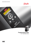
The Daily Temp Report / 2Hr provides two-hour averaged temperatures for each
Sensor during a 24-hour period. Displayed on the left hand side of the chart is
the Sensor name, Sensor ID, Alarming profile name, the temperature range, and
the interval for each Sensor.
A different reporting period can be selected by using the drop down reporting
period menu, the forward and backward arrows, or the calendar button.
Clicking on a temperature will display the Current Temperature History report for
that hour.
Note: Right click on graph to export information to EXCEL spreadsheet.
Daily Temperature Report / 12 Hour
To find the Daily Temp Report / 12Hr screen, go to Reports > Temp Trak > Daily
Temp Report / 1Hr. Click Daily Temp Report / 12Hr and the screen below will
appear:
www.cooper-atkins.com
13
Reports
Temp Trak Reference Guide
The Daily Temp Report / 12Hr provides the average temperature for each Sensor
during both the A.M. and P.M 12-hour reporting cycle. Each twelve-hour slot
contains the temperature. Displayed on the left hand side of the chart, is the
Sensor name, Sensor ID, Alarm profile, the temperature range, and the interval
for each Sensor.
A different reporting period can be selected by using the drop down reporting
period menu, the forward and backward arrows, or the calendar button.
Clicking on a temperature will display the Current Temperature History report for
the 12 hours.
Note: Right click on graph to export information to EXCEL spreadsheet.
Equipment QA Report
www.cooper-atkins.com
14
Reports
Temp Trak Reference Guide
To find the Monthly QA Temperature Report screen, go to Reports > Temp Trak
> Equipment QA Report. Click Equipment QA Report and the screen below will
appear:
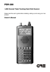
The above report provides a monthly equipment analysis by temperature point
(Sensor). The information displayed consists of:
Lowest and highest temperature readings collected.
Average temperature over the period.
Number of samples taken.
Number of samples out of range.
Percentage in range.
Quick pie chart displaying percentage of samples in range v/s samples
out-of-range.
Clicking on a Sensor will display the Daily Summary Report for the month.
A different reporting period can be selected by using the drop down reporting
period menu, the forward and backward arrows, or the calendar button.
www.cooper-atkins.com
15
Reports
Temp Trak Reference Guide
Note: Right click on graph to export information to EXCEL spreadsheet.
Daily Summary
To find the Temp Trak Summary By Day screen, go to Reports > Temp Trak >
Daily Summary. Click Daily Summary and the screen below will appear:
The Daily Summary Report displays the average temperature, minimum
temperature, maximum temperature, and the number of samples taken each day
for a selected Sensor. The report is divided into three main selections: A.M.,
P.M., and Entire Day.
A Sensor can be selected by using the Select Sensor drop-down list.
www.cooper-atkins.com
16
Reports
Temp Trak Reference Guide
Also available is the ability to choose an Ending Date and a Reporting Period.
Clicking on a temperature will display the Current Temperature History report for
that day.
Note: Right click on graph to export information to EXCEL spreadsheet.
Alerts By Day
To find the Alerts By Day screen, go to Reports > Temp Trak > Alerts By Day.
Click Summary By Day and the screen below will appear:
The Alerts By Day report displays the all temperature alerts which occurred
during a given day or time span. This includes both active and historical alert
conditions.
Alerts displayed in Red designate that the temperature was hotter than the
maximum temperature allowed, while those displayed in Blue mean the recorded
temperature was colder than the minimum temperature allowed.
Note: Right click on graph to export information to EXCEL spreadsheet.
Alerts / Notes By Sensor
www.cooper-atkins.com
17
Reports
Temp Trak Reference Guide
To find the Alerts By Sensor screen, go to Reports > Temp Trak > Alerts By
Sensor. Click Alerts/Notes By Sensor and the screen below will appear:
The Alerts By Sensor report displays the all temperature alerts for a specific
sensor which occurred during a given day or time span. This includes both
active and historical alert conditions. Also, previously relocated sensor alerts can
be displayed here as well by checking the “Include Previously Relocated
Sensors” checkbox.
Alerts displayed in Red designate that the temperature was hotter than the
maximum temperature allowed, while those displayed in Blue mean the recorded
temperature was colder than the minimum temperature allowed.
Note: Right click on graph to export information to EXCEL spreadsheet.
Temperature Graphs
To find the Temp Trak Temperature History screen, go to Reports > Temp Trak >
Sensor Reading Graphs. Click Sensor Reading Graphs and the screen below
will appear:
www.cooper-atkins.com
18
Reports
Temp Trak Reference Guide
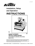
The Temp Trak Temperature History report provides an analysis of temperature
collections over an extended period of time. This report offers the following
information:
The graph displays three horizontal colored lines indicating:
o Blue indicates the minimum allowable temperature as defined on
the Sensor Attributes page.
o Red line indicates the maximum allowable temperature.
o Yellow line indicates the average temperature of the time frame.
Across the bottom of the graph, these lines are also indicated with a
numeric value.
The graph supports the ability to zoom in on a specific part of the graph to
display a more detailed and shorter time span. To zoom in on a specific
time period:
www.cooper-atkins.com
19
Reports
Temp Trak Reference Guide
o Left-click, holding down the mouse button, and drag the mouse
across the desired portion of the graph. The graph will redisplay
the new time frame.
o To reset the graph to the original time frame, click Unzoom.
Graph parameters can be changed by selecting the Change Graph
Parameters section:
o Select a Graph Period. The longer the period, the more
temperature points will be displayed.
o Select a new Report Ending Date by either entering in a date in the
format MM/DD/YYYY or by clicking the calendar button to bring up
a calendar button to select an ending date.
o Display Relocated Sensors.
o Select a Sensor from the list to report. Use the Ctrl key to select
multiple Sensors.
Right-clicking on a purple temperature point will display:
o The date/time stamp the temperature was taken.
o The Sensor name.
o The Temperature.
The Average Temperature of the graph’s time frame is displayed below
the temperature graph.
Daily Contact Sensor Report
www.cooper-atkins.com
20
Reports
Temp Trak Reference Guide
To find the Configuration Changes Report screen, go to Reports > Temp Trak >
Daily Contact Sensor Report. Click Daily Contact Sensor Report and the
screen below will appear:
If you are using the optional open/close detector switches with the Sensors, this
report will provide information on those pieces of equipment you are monitoring.
The information displayed consists of:
Number of times the door was opened.
Time the door was opened.
Time the door was closed.
Duration of each opening.
This can be extremely helpful in diagnosing temperature problems. It is not
uncommon to see walk-in doors propped open during deliveries, which will cause
temperatures to rise drastically
A different reporting period can be selected by using the drop down reporting
period menu, the forward and backward arrows, or the calendar button.
www.cooper-atkins.com
21
Reports
Temp Trak Reference Guide
Sensor Audit Report
To find the Configuration Changes Report screen, go to Reports > Temp Trak >
Sensor Audit Report. Click Sensor Audit Report and the screen below will
appear:
The Sensor Audit Report displays audit notes/comments made to any group of
sensors set up to accept audit notes (see Configuration > Temp Trak > Record
Sensor Audit). Three display selections are available:
Select User – Show only audits created by a specific user.
Select Sensor Group – Show audits for a specific sensor group.
Select Sensor – Show audits only for a specific sensor.
Once a selection is made, a similar screen to the one below will appear:
www.cooper-atkins.com
22
Reports
Temp Trak Reference Guide
Configuration Changes
To find the Configuration Changes Report screen, go to Reports > Temp Trak >
Configuration Changes. Click Configuration Changes and the screen below
will appear:
The Configuration Changes Report identifies changes made to any of the
configurations in the system and by whom. Fador example, if a temperature has
been changed for a specific Sensor that information will appear.
The report may be sorted by using the drop down reporting period menu, the
forward and backward arrows, or the calendar button.
www.cooper-atkins.com
23
Reports
Temp Trak Reference Guide
Temp Trak Mobile
Session Report
To find the Temp Trak Mobile Sensor Report screen, go to Reports > Temp Trak
Mobile > Session Report. Click Session Report and the screen below will
appear:
The Training Session Report logs information regarding each training form
launched. This report contains the following:
Description/Usage – Name of sensor.
Alarms – Displays any alarms that might have happened.
Start Time – Start time of data logger session.
Stop Time – Stop time of data logger session.
Duration – Length of time to complete the data logger session.
# Logged – Number of temperatures logged.
Notes – Notes about session.
Originating Location – Originating location where session was created.
Originating User – User who created session.
Logger ID – Logger ID.
Download Time – Time session information was loaded into the system.
To view a session’s Data Logger Detail Report:
Step 1 – Click on a data logger session. This will display the Data Logger Detail
Report as shown below.
www.cooper-atkins.com
24
Reports
Temp Trak Reference Guide
Upon selecting an entry from the Data Logger Session Report, the Data Logger
Detail Report is displayed. This report displays the following:
All session information from the Data Logger Session Report.
Sample frequency.
www.cooper-atkins.com
25
Reports
Temp Trak Reference Guide
Session notes and actions.
Data Logger temperature chart showing all temperatures recorded.
Alarm conditions encountered.
o Type: High or low
o Alarm Start: When the alarm condition started
o Duration: Amount of time of the alarm condition
Data Logger histogram showing the number of readings per temperature
range.
Data Logger Report
To find the Data Logger Report screen, go to Reports > Temp Trak Mobile >
Data Logger Report. Click Data Logger Report and the screen below will
appear:
The Data Logger Report shows each Data Logger currently registered on the
system:
Data Logger Serial Number
First Registered
# Session Programmed
# Sessions with Logs
Last User
Last session programmed
Last session description
Clicking on a Data Logger entry will bring up the Data Logger Detail Report
shown below.
www.cooper-atkins.com
26
Reports
Temp Trak Reference Guide
Each session of the Data Logger is displayed with some general session
information. For a detailed view of each session, click on the session and the
Data Logger Detail Report will appear (see Temp Trak Mobile Session Report).
www.cooper-atkins.com
27
Reports
Temp Trak Reference Guide
Administration
Database Backups
To find the Database Backup Report, go to Reports > Administration > Database
Backups. Click Database Backups.
Temp Trak may require the user to fill in the administrator User Name and
Password for the computer that they used to log into the COMPUTER, not into
Temp Trak.
User Name – User Name used to log into the computer.
Password – Password used to log into the computer.
Save this password in your password list – Saves the User Name and
Password information.
Once connected to the Local Host, the following screen will appear:
www.cooper-atkins.com
28
Reports
Temp Trak Reference Guide
The Database Backup Report confirms that the scheduled database backup has
been completed and the data has been written to the CD and/or hard drive. A
history of backups is kept which includes: File Name, Create Date, Last Modified,
and File Size. The location of the backup is also indicated.
Below is an example of a failed database backup.
www.cooper-atkins.com
29
Reports
Temp Trak Reference Guide
Job Status History
To find Job Status History, go to Reports > Administration > Job Status History.
Click Job Status History and the following screen will appear:
www.cooper-atkins.com
30
Reports
Temp Trak Reference Guide
The SQL Job Status History report displays activity performed against the IntelliWare database. Each line entry contains the Job Name, Job ID, Step ID, Step
Name, Message, Run Date, and the Run Duration hh:mm:ss.
Security / Audit Report
To find Job Status History, go to Reports > Administration > Security / Audit
Report. Click Security / Audit Report and the following screen will appear:
www.cooper-atkins.com
31
Reports
Temp Trak Reference Guide
The Security / Audit Report displays the user activity on the system, listing Log
Time, Action, User ID, Employee Name, Device Name, and Device Address.
To display only failed login attempts:
Step 1 – Click the checkbox Show Only Failures.
www.cooper-atkins.com
32
Reports
Temp Trak Reference Guide
Status Reports
Temp Trak Base Stations
To find the Database base stations, go to Reports > Administration > Status
Reports>TempTrak Base Stations. Click Temp Trak Base Stations.
Temp Trak may require the user to fill in the administrator User Name and
Password for the computer that they used to log into the COMPUTER, not into
Temp Trak.
User Name – User Name used to log into the computer.
Password – Password used to log into the computer.
Save this password in your password list – Saves the User Name and
Password information.
Once connected to the Local Host, the following screen will appear:
The Base Station Status Report displays the current status of all base stations.
This includes Base Type, Description/Location, Port, Settings, Register Time,
Enabled?, Last Data Received, Version, State, Ping Response and Last
Error/Message.
www.cooper-atkins.com
33
Reports
Temp Trak Reference Guide
By checking “Show Reporting Sensors”, an additional field is added to the list
showing all sensors the base station has received a temperature packet.
Temp Trak RF Topology
To find the Database Backup Report, go to Reports > Administration > Status
Reports > TempTrak RF Topology. Click TempTrak RF Topology.
Temp Trak may require the user to fill in the administrator User Name and
Password for the computer that they used to log into the COMPUTER, not into
Temp Trak.
User Name – User Name used to log into the computer.
Password – Password used to log into the computer.
Save this password in your password list – Saves the User Name and
Password information.
Once connected to the Local Host, the following screen will appear:
www.cooper-atkins.com
34
Reports
Temp Trak Reference Guide
The Temp Trak RF Topology report displays a graphical representation of how
each sensor has been reporting through which repeaters and base stations.
The Top->Bottom button displays the RF topology in a top to bottom format
where Sensors appear on the bottom.
The Left->Right button displays the RF topology in a left to right format where
Sensors appear on the right .
The Print Topology button allows the graph to be printed.
If this is the first time running the RF Topology screen, the following message
may appear:
www.cooper-atkins.com
35
Reports
Temp Trak Reference Guide
You will need to install the itGrid in order to see the RF Topology.
Note: Microsoft Internet Explorer may not allow this screen to be viewed properly due to Security
Rights. To properly display the contents of this page, make sure that Active X controls and plugins are set to either Enabled or Prompt in the Security tab of Internet Options.
Temp Trak RF Status
To find the Database Backup Report, go to Reports > Administration > Status
Reports > Temp Trak RF Status. Click Temp Trak RF Status and the following
screen will appear:
The Temp Trak RF Status report displays a chart showing the current status of
all services and the RF Topology.
If this is the first time running the RF Status screen, the following message may
appear:
www.cooper-atkins.com
36
Reports
Temp Trak Reference Guide
You will need to install the itGrid in order to see the RF Status.
Note: Microsoft Internet Explorer may not allow this screen to be viewed properly due to Security
Rights. To properly display the contents of this page, make sure that Active X controls and plugins are set to either Enabled or Prompt in the Security tab of Internet Options.
Intelli-Ware System Status Report
To find the Intelli-Ware System Status Report screen, go to Reports >
Administration > Status Reports >Service Status. Click Service Status and the
following screen will appear:
www.cooper-atkins.com
37
Reports
Temp Trak Reference Guide
The Intelli-Ware System Status Report displays the status of all relevant
services, which are specific to the successful functioning of the Intelli-Ware suite
of applications. Also, services can be stopped and started if necessary.
Database Server Information
To find the Database Server Information screen, go to Reports > Administration >
Status Reports > Database Information. Click Database Information and the
following screen will appear:
www.cooper-atkins.com
38
Reports
Temp Trak Reference Guide
The Database Server Information screen displays information about the Microsoft
SQL Server database as well as any concurrent activity violations.
Note: The version of Microsoft SQL Server, MSDE, that ships with the Intelli-Ware suite of products
is considered a light version and thus Microsoft only allows 5 concurrent users access to the
database at one time before the database automatically slows itself down.
www.cooper-atkins.com
39
Reports
Temp Trak Reference Guide
Configuration
Overview
Temp Trak’s configuration menu provides all the necessary utilities to configure
and customize all aspects of the program, from alarm profiles to user accounts to
devices registrations.
www.cooper-atkins.com
40
Configuration
Temp Trak Reference Guide
Temp Trak
Sensor Configuration
Sensor Attributes
To find the Sensor Attributes screen, go to Configuration > Temp Trak > Sensor
Configuration > Sensor Attributes. Click Sensor Attributes and the screen
below will appear:
Now that the Sensors have been installed and registered, it is time to create the
attributes that are specific to each Sensor. These attributes will include:
Sensor Name – User-defined sensor name.
Sensor ID – Sensor ID.
In Use? – Activates or deactivates a Sensor. This feature could be used if
a piece of equipment is broken and not operating correctly, you may
simple enter and turn off the Sensor, eliminates false alerts. Once the
device is operational, you may re-enter and activate the Sensor.
Logging Profile – Specifies what days/times to log temperatures.
www.cooper-atkins.com
41
Configuration
Temp Trak Reference Guide
Alarm Check Profile – Specifies which alarm profile (alerting profile) to
use.
Notification Profile – Specifies which people are to be notified via a predetermined profile.
Escalation Profile? – Specifies how the system should automatically
respond via notification profiles to a series of events.
Checking the “Show Extra Sensor Information” checkbox displays the following
additional information:
Probe – Defaults to 1 (currently not used).
Conditional Alarming - Contact Sensor – Sensor ID for the Contact
Sensor, which this sensor is set to alarm with.
Conditional Alarming - State – Current state of the Contact Sensor.
Notification Parameters - Pager Message – Unique page message utilized
if a pager alert type has been selected in the notification profile.
Notification Parameters - Relay Switch – Unique relay switch utilized if a
relay switch alert type has been selected in the notification profile.
Xmit Interval – Displays how frequently the Sensor is programmed to
transmit a temperature.
Temperature Probe Type – Allows for use of a variety of Temperature
types:
Note: Each Temperature type is specially designed to work within a certain
temperature range. I.E. Setting the attribute on a Sensors Temperature type to
broad-range, but using a standard Temperature on the Sensor will yield invalid
temperature data.
o Standard: Default for dual sensors.
o
Broad-Range: Allows for monitoring temperatures in excess of 200
degrees.
o Low-Temp: Allows for monitoring temperatures to –60 degrees F.
o Lab/Cryogenic RTD for monitoring temperatures -330°F to 32°F
o High Temp RTD for monitoring tempertatures 32°F to 300°F
Severity – Provides a means to assign a severity code to a Sensor that
has alerted (currently not used).
To change the Sensor attributes:
Step 1 – Referring to the log sheet created during the installation of the Sensors,
click on the appropriate Sensor number that you wish to configure. The Sensor
Attribute Maintenance screen will appear (See Sensor Attribute Maintenance).
www.cooper-atkins.com
42
Configuration
Temp Trak Reference Guide
Step 2 – Rename the Sensor to something unique and recognizable. Use the
Sensor Log for this, combining the location and equipment name. i.e. NW Refrig
Cafeteria.
Step 3 – Configure the rest of the attributes which where described earlier.
Step 4 – Once you have completed your configuration, click Save Changes.
Step 5 – Repeat steps 1-4 until all Sensors have been configured.
Sensor Attribute Maintenance
To find the Sensor Attributes Maintenance screen, go to Configuration > Temp
Trak > Sensor Configuration > Sensor Attributes. Click on a sensor and the
screen below will appear:
www.cooper-atkins.com
43
Configuration
Temp Trak Reference Guide
Each sensor can be modified with the appropriate profiles and attributes. These
include:
Sensor Name – User-defined sensor name.
Sensor ID – Sensor ID.
Temperature Probe Type – Allows for use of a variety of Temperature
types:
Note: Each Temperature probe is specially designed to work within a certain
temperature range. I.E. Setting the attribute on a Sensors Temperature type to
broad-range, but using a standard Temperature probe on the Sensor will yield
invalid temperature data.
o Standard: Default for internal and external Sensors.
o Broad-Range: Allows for monitoring temperatures in excess of 200
degrees.
o Low-Temp: Allows for monitoring temperatures to –60 degrees F.
o Lab/Cryogenic RTD for monitoring temperatures -330°F to 32°F
o High Temp RTD for monitoring tempertatures 32°F to 300°F
In Use? – Activates or deactivates a Sensor. This feature could be used if
a piece of equipment is broken and not operating correctly, you may
simple enter and turn off the Sensor, eliminates false alerts. Once the
device is operational, you may re-enter and activate the Sensor.
I Icon – Displays a detailed list of sensor information. This includes:
o Registration Date: Date sensor registered in system.
o Last Updated: Last date sensor attributes were modified.
o Last Base Station: Last date Base Station sensor contacted.
o Last Signal level/Margin: Last known signal strength.
o Last Contact: Last date sensor transmitted data.
o Last RESET Pressed: Last date reset button was pressed.
o Battery Status: Battery status.
o Temp Probe Status: Probe status (if external).
o Last Calibration: Status of sensor calibration.
Group Memberships – Scrolling list of groups the sensor is a member of.
Alert Severity – Provides a means to assign a severity code to a Sensor
that has alerted (currently not used).
Logging Profile – Dropdown list specifying what days/times to log
temperatures.
www.cooper-atkins.com
44
Configuration
Temp Trak Reference Guide
Alarm Check Profile – Dropdown list specifying which alarm profile
(alerting profile) to use.
Notification Profile – Dropdown list specifying which people are to be
notified via a pre-determined profile.
Escalation Profile – Dropdown list specifying how the system should
automatically respond if no actions have been taken on an outstanding
sensor alert.
A temperature sensor can be associated with a contact sensor. To do this, set
the following attributes:
Contact Sensor – The associated contact sensor.
Open/Close – The event in which the sensor should start processing.
There are times when a sensor-specific notification might be needed. In these
instances, set the following attributes:
Pager Message – Numeric page.
Relay Switch – Relay switch.
Sensor Message Formats – Create a sensor-specific message (see
Notification Message Format Maintenance).
Replace Sensor
To find the Replace Sensor screen, go to Configuration > Temp Trak > Sensor
Configuration > Replace Sensor. Click Replace Sensor and the screen below
will appear:
www.cooper-atkins.com
45
Configuration
Temp Trak Reference Guide
The Sensor Replacement screen allows for the easy replacement of a sensor
without having request a new sensor (from Cooper-Atkins) to be programmed
with the same Sensor ID as the one being replaced.
The new sensor must not be registered on the system. All historical data from
the sensor being replaced will be carried over to the new sensor. The sensor
name, alarm and notification parameters will also be carried over to the new
sensor.
To replace a sensor:
Step 1 – Select the old sensor to be replaced from the Select “Old” Sensor
Being Replaced drop-down list.
Step 2 – Enter the new Sensor ID.
Step 3 – Click Replace Sensor.
Relocate Sensor
To find the Relocate Sensor screen, go to Configuration > Temp Trak > Sensor
Configuration > Relocate Sensor. Click Relocate Sensor and the screen below
will appear:
www.cooper-atkins.com
46
Configuration
Temp Trak Reference Guide
The Relocate Temp Trak Sensor screen is used when a sensor is being moved
from one piece of equipment or location to another. All historical information
from the old location will remain available for reporting and a new set of
information will be recorded for the new location.
Warning: After relocating a Sensor, the computer must be rebooted in order for
Temp Trak to recognize the Sensors changed status.
To relocate a sensor:
Step 1 – Select the sensor to be moved from the Select Sensor Being Moved
To a New Location drop-down list.
Step 2 – Enter the new Sensor Name/Location Description.
Step 3 – Click Move Sensor.
Change Sensor Type
To find the Relocate Sensor screen, go to Configuration > Temp Trak > Sensor
Configuration > Change Sensor Type. Click Change Sensor Type and the
screen below will appear:
www.cooper-atkins.com
47
Configuration
Temp Trak Reference Guide
The Temp Trak Change Sensor Type screen is used when a Sensor has been
registered incorrectly on the Register Sensor page. For example, registering
Contact sensor as a Temperature sensor will cause invalid data.
Warning: Changing the sensor type could cause the Sensor to act incorrectly if
the wrong Sensor Type is assigned. I.E. Changing a Contact sensor to a
Temperature sensor will cause the Contact sensor to report incorrect values.
Warning: After changing a Sensor’s type, the computer must be rebooted in
order for Temp Trak to recognize the Sensors changed status.
To change a sensor type:
Step 1 – Select the Sensor Type from the drop-down list.
www.cooper-atkins.com
48
Configuration
Temp Trak Reference Guide
Step 2 – Select the new Transmission Interval from the drop-down list
(optional).
Note: Changing the Transmission Interval affects how some of the internal calculations are
processed. I.E Sensor Communication Failure Alert Options.
Step 3 – Click Save Changes.
Delete Sensors
To find the Delete Sensors screen, go to Configuration > Temp Trak > Sensor
Configuration > Delete Sensors. Click Delete Sensors and the screen below will
appear:
www.cooper-atkins.com
49
Configuration
Temp Trak Reference Guide
The Temp Trak Change Delete Sensor screen is used delete a Sensor plus all
related sensor information (history, alerts, notes, etc).
Warning: Deleting a Sensor will remove ALL information related to the Sensor.
This includes historical data, current data, etc.
To delete a sensor:
Step 1 – Click on the Check To Delete checkbox associated with the desired
sensor(s) to be deleted.
Step 2 – Click Delete Sensors.
www.cooper-atkins.com
50
Configuration
Temp Trak Reference Guide
Views / Groups
Group Configuration
To find the Temp Trak Sensor Group Configuration screen, go to Configuration >
Temp Trak > Views/Groups > Group Configuration. Click Group Configuration
and the screen below will appear:
Temp Trak Sensor Group Configuration provides the ability to create groups of
Sensors. Once a group has been created, it can be attached to a view.
To create a new Group:
Step 1 – Select New Group from the “Select a group to edit” drop-down list.
Step 2 – Click or tab to Group Name and enter a group name.
Step 3 – Click or tab to Map Layout Image and select a corresponding map, if
desired.
Step 4 – Click Add Group to add the group to the system.
To delete a Group:
Step 1 – Select the group from the “Select a group to edit” drop-down list.
Step 2 – Click Delete Group.
To view a Group:
Step 1 – Select the group from the “Select a group to edit” drop-down list.
To add sensors to a Group:
www.cooper-atkins.com
51
Configuration
Temp Trak Reference Guide
Step 1 – Select which Sensors to attach to the group by placing clicking the
checkbox next to the desired Sensor.
•
Sensors with a Gray background already belong to the group.
•
Sensors with a Yellow background do not belong to any group.
•
Sensors with a White background belong to other groups.
Step 2 – Click Enable Group Auditing to allow auditing notes to be added to
this group.
Step 3 – Click Save Group to update the group with the attached Sensors.
View Configuration
To find the Temp Trak View Maintenance screen, go to Configuration > Temp
Trak > Views/Groups > View Configuration. Click View Configuration and the
screen below will appear:
www.cooper-atkins.com
52
Configuration
Temp Trak Reference Guide
Temp Trak View Maintenance provides the ability to group Sensors together.
Once grouped, these views can be attached to users. The user will be
responsible for only the views attached to their Login ID.
To create a new View:
Step 1 – Select New View from the “Select a view to edit” drop-down list.
Step 2 – Click or tab to View Name and enter a view name.
Step 3 – Click or tab to View Title and enter a view title.
Step 4 – Click or tab to Sensors Per Row and select the number of Sensors to
display per row from the drop-down list.
Step 5 – Click or tab to Current Temps Display and select a display format from
the drop-down list:
Meter Dials
Numeric Values
Map Layout
Step 6– Click or tab to Map Layout Image and select a corresponding map, if
desired.
Step 7 – Click Add View to add the view to the system.
To delete a View:
Step 1 – Select the group from the “Select a view to edit” drop-down list.
Step 2 – Click Delete View.
To view a View:
www.cooper-atkins.com
53
Configuration
Temp Trak Reference Guide
Step 1 – Select the group from the “Select a view to edit” drop-down list.
To add groups to a View:
Step 1 – Select which Sensors and/or Groups to attach to this view.
•
Groups/Sensors with a Gray background already belong to the view.
•
Groups/Sensors with a White background have not been assigned to this
view..
www.cooper-atkins.com
54
Configuration
Temp Trak Reference Guide
Step 9 – Click Save View to update the view with the attached Sensors.
Group Profile Defaults
To find the Group Alarm Defaults screen, go to Configuration > Temp Trak >
Views/Groups > Group Profile Defaults. Click Group Alarm Defaults and the
screen below will appear:
The Temp Trak Sensor Group Alarm / Notification Maintenance screen provides
the ability to create default profiles for each group of Sensors.
To create a new group default profile:
Step 1 – Select the Sensor Group Name.
Step 2 – Select a Default Logging Profile from the drop-down list.
Step 3 – Select a Default Alarm Check Profile from the drop-down list.
Step 4 – Select a Default Notification Profile from the drop-down list.
Step 5 – Select a Default Escalation Profile from the drop-down list.
Step 6 – Provide a default Pager Message, if needed.
Step 7 – Select a Relay Switch, if needed.
Step 8 – Edit the Default Message Formats for the Group, if needed (see the
section, Message Formats).
Step 9 – Click Save.
Membership Summary
To find the Sensor View/Group Membership Summary screen, go to
Configuration > Temp Trak > Views/Groups > Membership Summary. Click
Membership Summary and the screen below will appear:
www.cooper-atkins.com
55
Configuration
Temp Trak Reference Guide
The Sensor View/Group Membership Summary screen displays whether a
Sensor is a member of a View or Group and, if the Sensor is currently in a View
or Group, the associated View or Group name.
View Map Configuration
To find the View Map Configuration screen, go to Configuration > Temp Trak >
View/Groups > View Map Configuration. Click View Map Configuration and the
screen below will appear:
www.cooper-atkins.com
56
Configuration
Temp Trak Reference Guide
The View Map Configuration screen, used in conjunction with the View
Configuration, displays a selected View Map Configuration, allowing for
placement of Sensors onto the map layout Also, double-clicking on the icon can
change each of the Sensor icons.
To select a map layout::
Step 1 – Select a map layout from the Select A View To Edit drop-down list.
Step 2 – Click Go > and the following screen will appear:
www.cooper-atkins.com
57
Configuration
Temp Trak Reference Guide
To place a Sensor on the map layout:
Step 1 – Left click and hold the mouse button down over a Sensor.
Note: Unplaced Sensor icons will be located in the Unplaced Sensors area.
Step 2 – Drag the Sensor icon to the desired location on the map and let go of
the mouse button.
Step 3- Repeat steps 1 and 2 until all Sensor icons have been placed.
Step 4 – Click Save Placement to save any changes.
www.cooper-atkins.com
58
Configuration
Temp Trak Reference Guide
To change a sensor’s icon:
Step 1 – Double-click on the Sensor’s icon and the following screen will appear:
Step 2 – Select an Image from the drop-down list.
Step 3 – Click the Select Image button.
Step 4 – Click Save Placement.
Note: The Save Placement button must be clicked in order to save the newly chosen Sensor’s
icon.
Group Map Configuration
To find the View Map Configuration screen, go to Configuration > Temp Trak >
View/Groups > Group Map Configuration. Click Group Map Configuration and
the screen below will appear:
www.cooper-atkins.com
59
Configuration
Temp Trak Reference Guide
The Group Map Configuration screen, used in conjunction with the Group
Configuration, displays a selected Group Map Configuration, allowing for
placement of Sensors onto the map layout. Also, double-clicking on the icon can
change each of the Sensor icons.
To select a map layout::
Step 1 – Select a map layout from the Select A Group To Edit drop-down list.
Step 2 – Click Go > and the following screen will appear:
To place a Sensor on the map layout:
www.cooper-atkins.com
60
Configuration
Temp Trak Reference Guide
Step 1 – Left click and hold the mouse button down over a Sensor located in the
Unplaced Sensors area.
Step 2 – Drag the Sensor icon to the desired location on the map and let go of
the mouse button.
Step 3- Repeat steps 1 and 2 until all Sensor icons have been placed.
Step 4 – Click Save Placement to save any changes.
To change a sensor’s icon:
Step 1 – Double-click on the Sensor’s icon and the following screen will appear:
Step 2 – Select an Image from the drop-down list.
Step 3 – Click the Select Image button.
Step 4 – Click Save Placement.
Note: The Save Placement button must be clicked in order to save the newly chosen Sensor’s
icon.
Map Import
To find the Layout Maintenance screen, go to Configuration > Temp Trak >
Views/Groups > Map Import. Click Map Import and the screen below will
appear:
www.cooper-atkins.com
61
Configuration
Temp Trak Reference Guide
The Map Import screen provides the ability to upload images into the Temp Trak
application for use as a map for visually attaching Sensors.
To upload a map layout file:
Step 1 – Enter the full path and filename of a layout map, or click Browse to
locate the layout map on the hard drive.
Note: The file extension must be either .GIF, .JPG, .BMP, or .WMF.
Step 2 – Enter the New File Name (optional). This will create a copy of the
original layout map and name it a new file name.
Step 3 – Enter a Description (optional) for the layout map.
Step 4 – Click Upload File.
The following screen will appear detailing the uploaded map layout:
www.cooper-atkins.com
62
Configuration
Temp Trak Reference Guide
To delete a map layout file:
Step 1 – Click the Delete button next to the desired Layout File Name.
To view an map layout file:
Step 1 – Click the View button next to the desired Layout File Name.
To delete a map layout file:
Step 1 – Click the Delete button next to the desired Layout File Name.
www.cooper-atkins.com
63
Configuration
Temp Trak Reference Guide
Device Registration
Register Sensors
To find the Sensor Registration screen, go to Configuration > Temp Trak >
Device Registration > Register Sensors. Click on Register Sensors and the
page below will appear:
To register a Sensor:
Step 1 – Select from the When registering Dual Temperature sensors dropdown box how you want to register the Dual Temperature sensors.
When registering Dual Temperature sensors: Assigns which channels
(internal and/or external) are active on dual temperature transmitters.
Step 2 – Click in an open Sensor ID box and type the Sensor ID (i.e. 1-34)
exactly as it appears on the packing box or the inside of the Sensor lid.
Step 3 –Tab or click in the next Transmitter Type drop-down box and select
from one of the transmitter types:
Dual Temperature – A transmitter placed on the outside of a unit being
monitored while a probe connected to the transmitter is threaded inside
the monitored unit (see Temp Trak Installation Guide for jumper settings).
Temperature + Humidity – A transmitter with a single integrated external
temperature & humidity sensor.
Single Temperature – A Sensor that is placed inside a unit to be tracked.
www.cooper-atkins.com
64
Configuration
Temp Trak Reference Guide
Contact – A Sensor designed to monitor contact between two devices.
Repeater – A Signal Repeater.
Step 4 – Click or tab to Assign To Group and select an existing group.
Note: Step 4 is optional but recommended if groups have been defined.
Step 5 – Click or tab to the next Sensor ID and continue the process until all
Sensors have been entered.
Step 6 – Once all Sensors have been entered, or all 20-entry boxes have been
filled, click Save.
The Sensors have now been registered to the system. You will see a note at the
top of the screen indicating that the registration was successful.
Note: It takes at least 5 minutes before the newly registered Sensors are activated.
Register Receiver
To find the Base Station Registration screen, go to Configuration > Temp Trak >
Device Registration > Register Receiver. Click on Register Receiver and the
screen below will appear:
The latest version of the Temp Trak software supports all hardware base station
versions starting with v3.0. The difference between the base types is as follows:
Base Server – Black buffer.
Base Receiver – Base station enclosed in a metal (silver) box with two
very thin black antenna on one end.
Base Receiver II – Base station enclosed in a plastic (white) box.
Intelli-Base – Black and gray buffer.
To register a Base Station via COM Port:
Step 1 – Select Base Receiver II (White) from the Base Type pull down menu.
Step 2 – Select the appropriate COM port from the Port pull down menu, and
click Yes for enabled.
Step 3 – Enter a Connection Password if needed.
www.cooper-atkins.com
65
Configuration
Temp Trak Reference Guide
Step 4 – Check the Enabled? check box to activate the base type.
Step 5 – Type in a Description / Location if needed.
Step 6 – Click Add.
The system has now registered and updated the base type registration file. (The
COM port must be the COM port that the base type hardware is attached to.)
Step 7 – Reboot the computer.
Note: In order for Intelli-Ware’s Temp Trak application to recognize the base type, the
computer must be rebooted.
To register a Base Station plugged into Black Buffer via COM Port:
Step 1 – Select Intelli-Base from the Base Type pull down menu.
Step 2 – Select the appropriate COM port from the Port pull down menu, and
click Yes for enabled.
Step 3 – Enter a Connection Password if needed.
Step 4 – Check the Enabled? check box to activate the base type.
Step 5 – Type in a Description / Location if needed.
Step 6 – Click Add.
The system has now registered and updated the base type registration file. (The
COM port must be the COM port that the base type hardware is attached to.)
Step 7 – Reboot the computer.
Note: In order for Intelli-Ware’s Temp Trak application to recognize the base type, the
computer must be rebooted.
To register a Base Station via Network Attach:
Step 1 – Select Base Receiver II (White) from the Base Type pull down menu.
Step 2 – Select Network Attached from the Port pull down menu.
Step 3 – Enter the IP Address of the base type (don’t change the Port from
1000).
Note: A serial to LAN converter unit is required. The System Administrator will supply the
IP address.
Step 4 – Enter a Connection Password if needed.
Step 5 – Check the Enabled? check box to activate the base type.
Step 6 – Type in a Description / Location if needed.
Step 7 – Select Add.
Step 8 – Reboot the computer.
Note: In order for Intelli-Ware’s Temp Trak application to recognize the base station, the
computer must be rebooted.
www.cooper-atkins.com
66
Configuration
Temp Trak Reference Guide
To register a Base Station plugged into Black Buffer via Network Attach:
Step 1 – Select Intelli-Base from the Base Type pull down menu.
Step 2 – Select Network Attached from the Port pull down menu.
Step 3 – Enter the IP Address of the base type (don’t change the Port from
1000).
Note: The IP Address of the base server must be configured using the Base Station
Configuration application found by going to “Start > All Programs > Ktg Intelli-Ware >
Tools > Base Station Configuration.” This application is described in the Appendix under
“Base Station Configuration”.
Note: If using the rectangular Sensors, the System Administrator will supply the IP
address.
Step 4 – Enter a Connection Password if needed.
Step 5 – Check the Enabled? check box to activate the base type.
Step 6 – Type in a Description / Location if needed.
Step 7 – Select Add.
Step 8 – Reboot the computer.
Note: In order for Intelli-Ware’s Temp Trak application to recognize the base station, the
computer must be rebooted.
www.cooper-atkins.com
67
Configuration
Temp Trak Reference Guide
Record Sensor Audit
To find the Temp Trak System Snapshot Audit screen, go to Configuration >
Temp Trak > Record Sensor Audit. Click Record Sensor Audit and the screen
below will appear:
The Temp Trak System Snapshot Audit screen provides the ability to create an
audit notes for sensors belonging to a sensor group.
Note: In order to create an audit record for a sensor group, the Enable Group Auditing checkbox
on the Group Configuration screen must first be checked for that group.
To create a system snapshot audit::
Step 1 – Type the comments/notes in the Audit Comments textbox.
Step 2 – Select which Sensor Groups the audit comments are associated with.
Step 3 – Click Save.
www.cooper-atkins.com
68
Configuration
Temp Trak Reference Guide
General Settings
To find the Temp Trak General Settings screen, go to Configuration > Temp Trak
> General Settings. Click General Settings and the screen below will appear:
The Temp Trak General Settings screen provides the following abilities:
Add/Customize additional Standard Alert Actions
Set the Temp Trak Data Retention Settings for database purges, ranging
from 1 week to 3 years or Keep All Data.
www.cooper-atkins.com
69
Configuration
Temp Trak Reference Guide
Modify Alert Processing to disable all alert notifications or to reset alerts
after each alert.
Configure Temp Trak to auto-register mini-sentries
Create Sensor Communication Failure Alert Options
o Alarm Delay Factor: Amount of delay, based on the Transmission
Interval
o Notification Profile: Sets which notification profile to use
o Escalation Profile: Sets which escalation profile to use
o Notification Parameters – Pager Message: Sets a pager message
which overrides any notification pager messages
o Notification Parameters – Relay Switch: Sets a relay switch which
overrides any notification relay switches
Change the Default Contact Sensor State Descriptions for contact
sensors.
To save temp trak general settings:
Step 1 – Modify/Change all desired fields.
Step 2 – Click Save.
www.cooper-atkins.com
70
Configuration
Temp Trak Reference Guide
Temp Trak Mobile
Display Logger Info
To find the Display Logger Info screen, go to Configuration > Temp Trak Mobile >
Display Logger Info. Click Display Logger Info and the screen below will
appear:
www.cooper-atkins.com
71
Configuration
Temp Trak Reference Guide
After a slight delay in which the Temp Trak system scans for a Data Logger input
device, this screen will display all the Data Logger information about the current
sensor attached to the Data Logger input device. This information includes, but
is not limited to, Session Description, Data Logger ID, Session Start Time,
Originating information, Sample Rate, Logged Samples, Alarm Conditions,
Min/Max Operating Ranges, Adapter Port, etc.
Besides displaying the Data Logger information, two buttons are present:
Re-Scan Logger: Provides a simple means of rescanning the current Data
Logger, or a new one.
Temp Trak Mobile Session: Opens the Temp Trak Mobile Session Report
for the attached Data Logger.
Save Logger Data
To find the Save Logger Data screen, go to Configuration > Temp Trak Mobile >
Save Logger Data. Click Save Logger Data and the screen below will appear:
www.cooper-atkins.com
72
Configuration
Temp Trak Reference Guide
The Save Logger Data screen is similar to the Display Logger Info screen but
with the addition a Session Notes / Corrective Actions section, as well as two
additional button: Record Data + CONTINUE Logging and Record Data + STOP
Logging.
Besides displaying the Data Logger information, four buttons are present:
www.cooper-atkins.com
73
Configuration
Temp Trak Reference Guide
Record Data + CONTINUE Logging: Records the data from the Data
Logger and continues logging information.
Record Data + STOP Logging: Records the data from the Data Logger
and stops recording information and stops the current Data Logger
session.
Re-Scan Logger: Provides a simple means of rescanning the current Data
Logger, or a new one.
Temp Trak Mobile Session: Opens the Temp Trak Mobile Session Report
for the attached Data Logger.
To save the logger data:
Step 1 – Enter some information in the Session Notes/Corrective Actions text
area.
Note: A value must be entered in the Session Notes/Corrective Actions text are to save the logger
data.
Step 2 – Click either the Record Data + CONTINUE Logging or Record Data +
STOP Logging button.
Configure Logger
To find the Sensor Attributes screen, go to Configuration > Temp Trak Mobile >
Configure Logger. Click Configure Logger. If a session is already in progress,
the following screen will appear prior to the Data Logger Setup screen:
If this happens, ONLY check the OK button if you have not saved the current
Data Logger information, otherwise all data will be lost.
If a session is not in progress for the currently attached Data Logger, the
following screen below will appear as long as a Temp Trak Mobile profile has not
been set up for the current user:
www.cooper-atkins.com
74
Configuration
Temp Trak Reference Guide
The Configure Logger screen provides the ability to create a new session for a
Data Logger. There are several pieces of information that must be entered in
order to create a new session for the Data Logger. These include:
Session Information: Description information about the current session
Logging Frequency. Determines the frequency which a the data logger
should record temperatures.
Allow Rollover: The Data Logger currently can store 2048 temperatures. If
the Data logger reaches this amount, a Yes in this field will allow the Data
Logger to replace the oldest value with the current temperature. A No in
this field means that when the Data Logger is full, no more temperatures
will be taken.
Alarm Range: Provides two fields for a minimum and maximum
temperature range. If a temperature is recorded that is outside this range,
an alarm condition will be generated.
To program a logger data:
Step 1 – Click in Session Information and enter the session information.
Step 2 – Select the Logging Frequency.
Step 3 – Select either Yes or No from the Allow Rollover drop-down list.
Step 4 – Enter the Alarm Range.
Step 5 – Click Program Data Logger.
www.cooper-atkins.com
75
Configuration
Temp Trak Reference Guide
If the Data Logger was programmed successfully, the following screen will
appear.
As an additional verification process, the following Configuration Verification
screen will appear, displaying all the currently programmed Data Logger
attributes:
To program another logger data:
Step 1 – Click Program Another.
If a Temp Trak Mobile Profile has been set up for the current user, then the
following Data Logger Setup screen will appear:
www.cooper-atkins.com
76
Configuration
Temp Trak Reference Guide
The difference between the default Data Logger and a Temp Trak Data Logger
profile attached to the current user is the inclusion of additional Session
Information created in the Profile Maintenance section under Temp Trak Mobile.
www.cooper-atkins.com
77
Configuration
Temp Trak Reference Guide
Setup
Profile Maintenance
To find the Sensor Attributes screen, go to Configuration > Temp Trak Mobile >
Profile Maintenance. Click Profile Maintenance and the screen below will
appear:
A profile for a Data Logger can be created so that a known series of destination
and prompts can be assigned to a user monitoring the Data Logger. The
assigning of the Temp Trak Mobile Profile is handled in the Security>Users
section.
To create a temp trak mobile profile:
Step 1 – Enter a Program Name.
Step 2 – Enter the Destination.
Note: Pressing the Tab button will create a new destination, allowing for multiple destinations.
Step 3 – Enter the Prompts.
Note: Pressing the Tab button will create a new prompt, allowing for multiple prompts.
Step 4 – Click Add Profile.
To modify an existing temp trak mobile profile:
www.cooper-atkins.com
78
Configuration
Temp Trak Reference Guide
Step 1 – Select the profile from the Select a profile to edit drop-down list.
Step 2 – Modify any existing information.
Note: Pressing the Tab button while in the destinations or prompts area will create a new entry
allowing for multiple destinations.
Step 3 – Click Save Profile.
To delete an existing temp trak mobile profile:
Step 1 – Select the profile from the Select a profile to edit drop-down list.
Step 2 – Click Delete Profile.
Setup Collector PC
To find the Sensor Attributes screen, go to Configuration > Temp Trak Mobile >
Setup > Setup Collector PC. Click Setup Collector PC and the screen below
will appear:
The Setup Collector PC screen will install some additional drivers for the Temp
Trak Mobile input device. There is the possibility of some Windows Security
screens appearing. Click the Run button when these appear. Once the
warnings have passed, the screen below will appear. Please follow the
instructions for the 1-Wire driver installation.
www.cooper-atkins.com
79
Configuration
Temp Trak Reference Guide
If the Temp Trak Mobile input device is currently attached to a COM port during
installation, the following screen might appear. Please follow the instructions.
The 1-Wire Port Selection screen will appear asking for a port to search for the
Temp Trak Mobile input device. At this point, reattach the Temp Trak Mobile
input device. Select the COM port that the Temp Trak Mobile input device will be
attached to, then click OK. If the COM port is unknown, click the Auto-Detect
button.
The installation of the Temp Trak Mobile input device drivers is now complete
and the Data Loggers can be configured.
www.cooper-atkins.com
80
Configuration
Temp Trak Reference Guide
Alarm Configuration
Profile Setup
Logging Profiles
To find the Alarm Profile Maintenance screen, go to Configuration > Alarm
Configuration > Profile Setup > Logging Profiles. Click Logging Profiles and the
screen below will appear:
Temp Trak includes a default logging profile, 15 Mins/Average/No Delta. By
selecting the profile from the “Select a profile to edit:” drop-down list, the
following appears:
The Logging Profile Maintenance screen configures the time interval for logging
temperatures received from a sensor. By default (factory hard set), a basic
sensor transmits a temperature packet every five minutes. Thus, if the default
logging profile is used (15/Average/No Delta), Temp Trak will receive three
www.cooper-atkins.com
81
Configuration
Temp Trak Reference Guide
temperature packs, average them, and provide a temperature to log for that
sensor.
Note: It is best to choose the default logging profile of 15/Average/No Delta due to the massive
amounts of data that would be recorded otherwise.
There are specific attributes that can be chosen from when setting up a logging
profile. These include:
Logging Profile Name – User-defined name, normally includes the logging
interval.
Enabled – Sets whether the logging profile is active or inactive.
Description – User-defined description of the logging profile
Enabled – Sets whether the logging profile is active or inactive.
Week Days – Allows the Sensor to be active on specific days or all week.
Start Time - End Time – Determines the time during the day to start and
stop logging temperatures.
Log Only During Alarm Periods – Works in conjunction with an Alarm
profile and logs temperatures only during the times and days the Alarm
profile is active.
Log Only With Contact Sensor – Works in conjunction with a Contact
Sensor (defined on the Sensor Attributes Maintenance screen), logging
temperatures when the Contact Sensor is active.
Logging Interval – Time interval which the sensor will log temperatures.
FEM Only)
Delta Logging Value – Percent change to initiate the start logging
temperatures.
Log Value – Determines what value should be logged (average, minimum,
maximum, last value) at log time.
Alert Check – Determines at what point to check the Sensor’s Alarm
profile.
To add a new logging profile:
Step 1 – Select –New Profile – from the Select a profile to edit drop-down list.
Step 2 – Click in the Logging Profile Name field and enter the logging name.
Step 3 – Check Enabled.
Step 4 – Click Add New Profile.
Step 5 – Click in the Description field and enter a description.
Step 6 – Configure the rest of the attributes which where described above.
www.cooper-atkins.com
82
Configuration
Temp Trak Reference Guide
Step 7 – Once you have completed your configuration, click Add.
Step 8 – Repeat steps 5-7 until all alarms have been configured.
To change an existing logging profile:
Step 1 – Click on the logging Description you wish to update.
Step 2 – Configure the rest of the settings which where described earlier.
Step 3 – Once you have completed your configuration, click Update.
To delete an existing logging profile:
Step 1 – Click on the logging Description you wish to delete.
Step 2 – Click Delete.
Alarm Profile Maintenance
To find the Alarm Profile Maintenance screen, go to Configuration > Alarm
Configuration > Profile Setup > Alarm Profiles. Click Alarm Profiles and the
screen below will appear:
Temp Trak provides three distinct alarm profile templates: Temperature ,Contact
and Humidity. A sample screen, representing a temperature profile is presented
below.
www.cooper-atkins.com
83
Configuration
Temp Trak Reference Guide
The Alarm Profiles Maintenance screen provides a way to customization alarm
events, ranging from temperatures, to selected days, to start/end times, to alert
methods and severity. Also, based on the type of sensor, additional fields may
be present.
There are specific attributes that can be chosen from when setting up an alarm
profile. These will include:
Alarm Profile Name – User-defined name, normally includes the Sensor
name.
Enabled – Sets whether the alarm is active or not active.
Profile for Sensor Types – Sensor template chosen depending on type of
sensor (Temperature, Contact or Humidity).
Description – User-defined description of the alarm profile
Enabled – Sets whether the alarm is active or not active.
Min Temp – Generates an alarm when the temperature monitored by the
Sensor falls below this value.
Note: Only used with a temperature profile.
Max Temp – Generates an alarm when the temperature monitored by the
Sensor rises above this value.
Note: Only used with a temperature profile.
Alarm If… – Alarm based on the condition of being closed or opened.
Note: Only used with a contact profile.
Alarm Delay (Minutes) – Sets the number of minutes that must pass while
a sensor is out of range before an alarm event is initiated.
Week Days – Allows the Sensor to be active on specific days or all week.
www.cooper-atkins.com
84
Configuration
Temp Trak Reference Guide
Start Time - End Time – Determines the time during the day to start and
stop monitoring temperatures for an alarm event.
Alarm Only With Contact Sensor – The sensor will only alarm if working in
conjunction with a Contact sensor (see Conditional Profile Processing on
the Sensor Attributes Maintenance screen).
Note: Only used with a temperature profile.
Severity – Sets a severity level (currently not used).
Ordering – Used to change the ordering of the alarm conditions.
To add a new alarm within a profile:
Step 1 – Select –New Profile – from the Select a profile to edit drop-down list.
Step 2 – Click in the Alarm Profile Name field and enter the alarm name.
Step 3 – Check Enabled.
Step 4 – Select the sensor type from the Profile for Sensor Types drop-down
list.
Step 5 – Click Add New Profile.
Step 6 – Click in the Alarm Name field and enter an alarm name.
Step 7 – Configure the rest of the attributes which where described above.
Step 8 – Once you have completed your configuration, click Add.
Step 9 – Repeat steps 6-8 until all alarms have been configured.
To change an existing alarm within a profile:
Step 1 – Click on the Alarm Name you wish to update.
Step 2 – Configure the rest of the settings which where described earlier.
Step 3 – Once you have completed your configuration, click Update.
To delete an existing alarm within a profile:
Step 1 – Click on the Alarm Name you wish to delete.
Step 2 – Click Delete.
Notification Profile Maintenance
To find the Notify Profiles screen, go to Configuration > Alarm Configuration >
Profile Setup > Notify Profiles. Click Notify Profiles and the screen below will
appear:
www.cooper-atkins.com
85
Configuration
Temp Trak Reference Guide
The Notification Profiles Maintenance screen allows the user to define notification
profiles for event alarms. Each profile can be customized to include days of the
week, starting and ending times, and notification methods. A sample screen,
representing a temperature profile is presented below.
There are specific attributes that can be chosen from when setting up a
notification profile. These will include:
Notification Profile Name – User-defined name.
Enabled – Sets whether the profile is active or not active.
Description – User-defined description of the notification profile
Enabled – Sets whether the profile is active or not active.
Days – Allows the profile to be active on specific days or all week.
Start Time - End Time – Determines the time during the day to start and
stop monitoring temperatures for a notification event.
Notification Method – Sets the profiles notification method.
www.cooper-atkins.com
86
Configuration
Temp Trak Reference Guide
o Server Popup (generates a pop-up window on the host PC)
o Send Page (numeric)
Select the person(s) the pager notification will page from the
Pager Info drop-down list.
Click or tab to Message and enter a numeric message.
o Send E-mail
Select a person(s) from the Email To drop-down box to
email.
o Remote Popup
Select a person(s) from the Popup To drop-down box to
generate a pop-up window on the remote PC.
o Message Board
Select a defined Message Board from the To drop-down box
to notify via a message board.
o Relay Switch
Select a defined Relay Switch and associated Relay from
the drop-down lists.
o Custom Script
For advanced users. Please contact Technical Support for
details.
Show Celsius For Temps – Displays temperatures in Celsius.
Ordering – Used to change the ordering of the notification conditions.
To add a new notification profile:
Step 1 – Select –New Profile – from the Select a profile to edit drop-down list.
Step 2 – Click in the Notification Profile Name field and enter the notification
name.
Step 3 – Check Enabled.
Step 4 – Click Add New Profile.
Step 5 – Click in the Notification Name field and enter the notification name.
Step 6 – Configure the rest of the attributes which where described above.
Step 7 – Once you have completed your configuration, click Add.
Step 8 – Repeat steps 5-7 until all profiles have been configured.
To change an existing notification profile:
Step 1 – Click on the Notification Name you wish to update.
www.cooper-atkins.com
87
Configuration
Temp Trak Reference Guide
Step 2 – Configure the rest of the settings which where described earlier.
Step 3 – Once you have completed your configuration, click Update.
To delete an existing notification profile:
Step 1 – Click on the Notification Name you wish to delete.
Step 2 – Click Delete.
Escalation Profiles
To find the Escalation Profiles screen, go to Configuration > Alarm Configuration
> Profile Setup > Escalation Profiles. Click Escalation Profiles and the screen
below will appear:
The Escalation Profiles Maintenance screen allows the user to define custom
escalation rules based on the elapsed time from the start of the alarm. Each
profile can be customized for up to five escalations and one failsafe notification.
A sample screen, representing a notification profile is presented below.
www.cooper-atkins.com
88
Configuration
Temp Trak Reference Guide
There are certain attributes that can be modified for each Escalation Profile:
Escalation Profile Name – User-defined name.
Enabled – Sets whether the profile is active or not active.
[Minutes Box] – Sets the number of minutes after an alarm condition and
after each prior Escalation Rule before the Escalation Rule takes affect.
[-Select Profile-] – The Notification profile to be used when the Escalation
Rule takes affect.
www.cooper-atkins.com
89
Configuration
Temp Trak Reference Guide
Pager Prompt/Message – Numeric page message that overrides any
existing notification pager message.
Note: Only used if a Pager Notification profile is selected.
Relay Switch – Sends an event to the specified Relay Switch.
Severity – Sets a severity level (currently not used).
To add a new escalation profile:
Step 1 – Select –New Profile – from the Select a profile to edit drop-down list.
Step 2 – Click in the Escalation Profile Name field and enter the escalation
name.
Step 3 – Check Enabled.
Step 4 – Click Add New Profile.
Step 5 – Click in the Escalation Name field and enter the notification name.
Step 6 – For each escalation rule, enter the number of minutes to which the rule
will take effect.
Note: This is the number of minutes from the last escalation rule.
Step 7 – Select a Notification profile.
Step 8 – Select a Pager/Message, if necessary.
Step 9 – Select a Relay Switch, if necessary.
Step 10 – Repeat steps 6-9 until all rules have been configured.
Step 11 – Enter a Failsafe Notification rule.
Step 12 – Click Save Escalation Rules.
To change an existing escalation profile:
Step 1 – Click on the Escalation Name you wish to update.
Step 2 – Configure the rest of the settings which where described earlier.
Step 3 – Once you have completed your configuration, click Save Escalation
Rules.
To delete an existing escalation profile:
Step 1 – Click on the Escalation Name you wish to delete.
Step 2 – Click Delete Profile.
www.cooper-atkins.com
90
Configuration
Temp Trak Reference Guide
Address Book Setup
Digital Pagers
To find the Pager Notification Configuration screen, go to Configuration > Alarm
Configuration > Address Book Setup > Digital Pagers. Click Digital Pagers and
the screen below will appear:
This screen is used when digital pagers are utilized for alert notifications. At this
time, the Intelli-Ware application only supports a numeric message, i.e. 911, in
the Default Message field.
There are two special characters that should be noted:
Comma (,) – Used to add a slight delay in the Phone Number field.
Pound Sign (#) – Used to end a sequence in the Phone Number field as
well as the Default Message field.
To add a new Digital Pager:
Step 1 – Click in the Pager Name box and enter the pager name.
Step 2 – Click or tab to Phone Number and enter a phone number.
Step 3 – Click or tab to Delay and add a delay.
Note: Delay is the time delay from when the phone number is dialed till when the pager
service accepts the page message.
Step 4 – Click or tab to Default Message and add a numeric message.
Note: Use Count displays how many times this Digital Pager has been assigned.
Step 5 – Click Add to add the new Digital Pager to the system.
www.cooper-atkins.com
91
Configuration
Temp Trak Reference Guide
To update an existing Digital Pager:
Step 1 – Click on an existing Digital Pager alert. The information will then
appear in the blue edit box.
Step 2 – Make the appropriate changes.
Step 3 – Click Save. The Digital Pager will be automatically updated.
To remove an existing Digital Pager:
Step 1 – Click on an existing Digital Pager.
Step 2 – Click Delete. The Digital Pager will be automatically deleted.
Emails / Alpha Pagers
To find the Email Notification Configuration screen, go to Configuration > Alarm
Configuration > Address Book Setup > Emails / Alpha Pagers. Click Emails /
Alpha Pagers and the screen below will appear:
This screen is used when emails or alpha pagers are utilized for alarm
notifications.
To add a new Email alert:
Step 1 – Click in the Email Name box and enter the email name.
Step 2 – Click or tab to Email Address and enter an email address.
Note: Use Count displays how many times this Email Alert has been assigned.
Step 3 – Check the Email Is Alpha Pager if this entry is for an alpha pager.
Step 4 – Click Add to add the new Email Alert to the system.
To update an existing Email alert:
Step 1 – Click on an existing Email Alert. The information will then appear in the
blue edit box.
www.cooper-atkins.com
92
Configuration
Temp Trak Reference Guide
Step 2 – Make the appropriate changes.
Step 3 – Click Save. The Email Alert will be automatically updated.
To remove an existing Email alert:
Step 1 – Click on an existing Email Alert.
Step 2 – Click Delete. The Email Alert will be automatically deleted.
Relay Switches
To find the External Relay Switch Notification Configuration screen, go to
Configuration > Alarm Configuration > Address Book Setup > Relay Switches.
Click Relay Switches and the screen below will appear:
This screen is used create a relay switch alert notification for an open/close
contact relay switch. Currently, up to 8 switches are supported.
To add a new Alert Relay:
Step 1 – Click in the Relay Switch Name box and enter the relay switch name.
Step 2 – Click or tab to Port and select the port the relay switch is connected to.
Step 3 – Click Add to add the new Relay Switch to the system.
Note: To assign Sensors to a Relay Switch, see the section title Sensor Attributes.
To update an existing Alert Relay:
Step 1 – Click on an existing Relay Switch Name. The information will then
appear in the blue edit box.
Step 2 – Make the appropriate changes.
Step 3 – Click Save. The Relay Switch will be automatically updated.
To remove an existing Alert Relay:
www.cooper-atkins.com
93
Configuration
Temp Trak Reference Guide
Step 1 – Click on an existing Relay Switch Name.
Step 2 – Click Delete. The Relay Switch will be automatically deleted.
Remote Popups
To find the Net Send Notification Configuration screen, go to Configuration >
Alarm Configuration > Address Book Setup > Remote Popups. Click Remote
Popups and the screen below will appear:
This screen is used to create a remote popup distribution list for sending
network-wide alarm notifications. A sample notification looks like the following:
To add a new Remote Popup:
Step 1 – Click in the Name box and enter a descriptive name.
www.cooper-atkins.com
94
Configuration
Temp Trak Reference Guide
Step 2 – Click or tab to Destinations and enter a destination. The destination
can be a network user id or computer id.
Note: Use Count displays how many times this Email Alert has been assigned.
Step 3 – Click Add to add the new Remote Popup to the system.
To update an existing Remote Popup:
Step 1 – Click on an existing Name. The information will then appear in the blue
edit box.
Step 2 – Make the appropriate changes.
Step 3 – Click Save. The Remote Popup will be automatically updated.
To remove an existing Remote Popup:
Step 1 – Click on an existing Name.
Step 2 – Click Delete. The Remote Popup will be automatically deleted.
Message Boards
To find the Message Board Notification Configuration screen, go to Configuration
> Alarm Configuration > Address Book Setup > Message Boards. Click Alert
Message Board and the screen below will appear:
This screen is used to define a message board alert notification for a message
box.
To add a new Message Board:
Step 1 – Click in the Message Board Name and enter the message board
name.
Step 2 – Click or tab to Type / Model and select the type of message board.
Step 3 – Click or tab to Port and select the port the message board is connected
to.
www.cooper-atkins.com
95
Configuration
Temp Trak Reference Guide
Step 4 – Click Add to add the new Message Board to the system.
Note: To assign Sensors to a Message Board, see the section title Sensor Attributes.
To update an existing Message Board:
Step 1 – Click on an existing Message Board Name. The information will then
appear in the blue edit box.
Step 2 – Make the appropriate changes.
Step 3 – Click Save. The Message Board will be automatically updated.
To remove an existing Message Board:
Step 1 – Click on an existing Message Board Name.
Step 2 – Click Delete. The Message Board will be automatically deleted.
www.cooper-atkins.com
96
Configuration
Temp Trak Reference Guide
Notification Groups
To find the Notification Group Maintenance screen, go to Configuration > Alarm
Configuration > Notification Groups. Click Notification Groups and the screen
below will appear:
Notification Group Maintenance allows you to group any number of recipients for
an alert for a specific sensor. This works with Emails, Pagers, Remote Popups,
and Message Boards.
Note: There must be an existing Pager, Email, Remote Popup, or Message Board
configured in order to complete this process.
To add a new Notification Group:
Step 1 – Click in the Group Name box and enter the group name.
Step 2 – Click or tab to Group Type and select either Pager, Email, Remote
Popup, or Message Board from the drop-down box.
Note: # Members displays how many entries are grouped together.
Step 3 – Click Add to add the new Notification Group to the system.
Step 4 – Click on the newly created Notification Group. The information will then
appear in the blue edit box.
Step 5 – Click [Edit…] in the # Members field to attach the desired entry to this
group. This will bring up the Notification Group Membership Maintenance screen
as shown on the following page.
www.cooper-atkins.com
97
Configuration
Temp Trak Reference Guide
Step 6 – Select the entry from the list to include as members.
Step 7 – Click Save to update the Notification Group with the selected new
members.
To update an existing Notification Group:
Step 1 – Click on an existing Notification Group. The information will then
appear in the blue edit box.
Step 2 – Make the appropriate changes.
Note: The group type cannot be changed. Instead, the Notification Group must be deleted
and added again with the new group type.
Step 3 – Click Save. The Notification Group will be automatically updated.
To remove an existing Notification Group:
Step 1 – Click on an existing Notification Group.
Step 2 – Click Delete. The Notification Group will be automatically deleted.
www.cooper-atkins.com
98
Configuration
Temp Trak Reference Guide
Message Formats
To find the Notification Message Format Maintenance screen, go to
Configuration > Alarm Configuration > Message Formats. Click Message
Formats and the screen below will appear:
The Notification Message Format Maintenance screen allows for customization
of messages sent with each sensor alert.
To update a message:
Step 1 – Click in either the Pop-up Window, Remote Popup, Message Board,
Email Subject (Alpha Pagers), Email Body (Alpha Pagers), Email Subject, or
Email Body field and enter the new text.
Note: The Message Substitution Tags, i.e. %%ID%%, etc, can be removed or rearranged.
Step 2 – Click Save Messages and the messages will automatically be updated.
www.cooper-atkins.com
99
Configuration
Temp Trak Reference Guide
Relay Use Summary
To find the External Relay Switch Usage Summary screen, go to Configuration >
Alarm Configuration > Relay Use Summary. Click Relay Use Summary and the
screen below will appear:
The External Relay Switch Usage Summary screen displays any Sensors
attached to a relay switch. A red box denotes the attachment. A red box with an
“A” signifies that there is an advanced alarm attached also.
www.cooper-atkins.com
100
Configuration
Temp Trak Reference Guide
Setup PC For Popups
To find the Setup PC For Popups screen, go to Configuration > Alarm
Configuration > Setup PC For Popups. Click Setup PC For Popups and the
screen below will appear:
In order to displays Local Popup notifications and Remote Popup Notifications,
the IWPopup application must be installed on the system where the popup alarm
will be displayed.
Installing onto the local (Temp Trak) computer:
Step 1 – Follow the installation instructions.
Step 2 – Click Start>All Programs>Intelli-Ware Popup Notifications>Intelli-Ware
Popup. This will launch the IWPopup program allowing for popup notifications.
Note: A small red buzzer icon will appear on the task bar on the lower right side of the screen.
Installing onto a remote computer:
Step 1 – Obtain the IP address of the Temp Trak computer.
Step 2 – On the remote computer, open Internet Explorer. In the Address line,
type the following, substituting the words, IP Address, for the IP address of the
computer which Temp Trak was installed on:
IP Address/Intelli-Ware
Step 3 – Log onto Temp Trak and go to Configuration>Alarm
Configuration>Setup PC For Popups.
Step 4 – Follow the installation instructions
Step 5 – Click Start>All Programs>Intelli-Ware Popup Notifications>Intelli-Ware
Popup. This will launch the IWPopup program allowing for popup notifications.
Step 6 – A small red buzzer icon will appear on the task bar on the lower right
side of the screen. Right click on the icon and select Configure.
Step 7 – In the field Intelli-Ware Server, enter the IP address of the Temp Trak
computer, then click the OK button.
www.cooper-atkins.com
101
Configuration
Temp Trak Reference Guide
Administration
Security
Users
To find the User Maintenance screen, go to Configuration > Administration >
Security > Users. Click Users and the screen below will appear:
This screen establishes all system users and their level of access. The system
will recognize each user individually along with their specific parameters.
Note: The default temperature and language of the system is Fahrenheit and English.
To add a new user:
Step 1 – Click in the Login ID box and enter the new Login ID.
Step 2 – Click or tab to First Name and enter the user’s first name.
Step 3 – Click or tab to Last Name and enter the user’s last name.
Step 4 – Click or tab to Employee ID and enter the user’s employee ID.
Note: Employee ID is optional.
Step 5 – Click or tab to Level and select the Access Level of the user from the
pull-down box.
Step 6 – Click or tab to Password and enter the user’s password.
Step 7 – Click the Show Celsius check box to display all temperatures in
Celsius, if desired.
Step 8 – Click the Login Disabled check box to disable the user, if desired.
Note: A check in the Login Disabled box indicated the user is not able to login the IntelliWare application.
www.cooper-atkins.com
102
Configuration
Temp Trak Reference Guide
Step 9 – Click the Account Disabled check box to disable the an account.
Step 10 – Click the Account Locked Out check box to lock out a user.
Step 11 – Click the Must Change Password check box to force a user to
change their password the next time they log in.
Step 12 – Click or tab to Language and select the language the user wishes to
display all information.
Step 13 – Click or tab to Temp Trak View to select which sets of Sensors the
user is allowed to view (see View Configuration).
Step 14 – Click or tab to Temp Trak Mobile Profile to select which profile the
user is allowed to view (see Profile Maintenance in the Temp Trak Mobile
section).
Step 15 – Click Add to add the new User to the system.
Note: A user needs a minimum of a login ID and a password.
To update an existing user:
Step 1 – Click on an existing user. Their information will then appear in the blue
edit box.
Step 2 – Make the appropriate changes.
Step 3 – Click Save. The user will be automatically updated.
To remove an existing user:
Step 1 – Click on an existing user.
Step 2 – Click the Logon Disabled check box.
Step 3 – Click Save. The user will be automatically disabled.
Note: Due to audit purposes, the system attaches individuals to specific historical
information, so they will not be deleted from the database, only disabled.
Access Rights
To find the Access Permissions Maintenance screen, go to Configuration >
Administration > Security > Access Rights. Click Access Rights and the screen
below will appear:
www.cooper-atkins.com
103
Configuration
Temp Trak Reference Guide
www.cooper-atkins.com
104
Configuration
Temp Trak Reference Guide
Access Permissions determine the Role levels that are needed to access
applications and functions. These include: Maintenance Applications, Security
Configurations, System Configurations and Reports.
To modify an Application or Function:
Step 1 – Under Applications, click on the drop down arrow list in the Minimum
Level column and choose from the Role levels that were established in the Role
Maintenance function. The level you choose will be the minimum level of access.
Note: Application Name can be renamed to better fit your organizational naming
standards.
Step 2 – Under Functions, repeat the same as above for each Functional Area
available.
Roles
To find the Role Maintenance screen, go to Configuration > Administration >
Security > Roles. Click Roles and the screen below will appear:
Intelli-Ware provides a high level of security so access to specific applications will
be provided only to those people granted permission. These permissions can be
divided not only by application, but also by configurations, reports, etc.
I.e.: One person may have permission to only view reports, while another person
may have permission to view reports, as well as make system configurations.
It is necessary to determine the Role Description, i.e. Manager, Assistant
Manager, etc., and the Access Level associated with each description. The
lower the Access Level’s number, the lower the access permissions. The system
has been designed to support 999 different security levels.
www.cooper-atkins.com
105
Configuration
Temp Trak Reference Guide
Note: You may want to leave numbers between your levels so you can add levels in the
future.
To add a new Role:
Step 1 – Click in the Role Description box and enter the Role description.
Step 2 – Click in, or tab to, the Access Level box and add the appropriate Access
Level number.
Step 3 – Click Add. The new Role will be added.
To update an existing Role:
Step 1 – Click on the existing Role Description or Access Level that you wish to
change. It will appear in the blue edit box.
Step 2 – Make the necessary changes.
Step 3 – Click Save. The existing Role will be updated.
To delete an existing role:
Step 1 – Click on the existing Role Description or Access Level that you wish to
delete. It will appear in the blue edit box.
Step 2 – Click Delete. The Role will be deleted.
Password Options
To find the Role Maintenance screen, go to Configuration > Administration >
Security > Password Options. Click Password Options and the screen below
will appear:
www.cooper-atkins.com
106
Configuration
Temp Trak Reference Guide
The Password Option Maintenance screen allows for the global setting of
password configurations. These include:
Minimum Password Length: Minimum password length allowed by system.
Maximum Password Age (Days): Maximum number of days before
requiring a new password.
Minimum Password Age (Days): Minimum number of days required before
a new password can be created. Thus, a user cannot create a password
then change it immediately.
Account Lockout Threshold (# Invalid Attempts): Number of consecutive
failed login attempts before the account is locked out.
Reset Account Lockout Automatically After (Minutes): Resets any lockedout accounts automatically after a specified number of minutes.
Note: Setting the Reset Account Lockout Automatically After (Minutes) to zero would and
setting the Account Lockout Threshold (# Invalid Attempts) to anything other than zero
will require an administrator to reset the Account Locked Out checkbox on the User
Maintenance screen before the user can log in.
Enforce Password History (# To Remember): Keeps a specified number of
passwords to check against, requiring the user to enter a unique
password.
Enable User-Defined Check: Allows user-controlled password logic to be
implemented.
www.cooper-atkins.com
107
Configuration
Temp Trak Reference Guide
General Settings
To find the General System Settings screen, go to Configuration > Administration
> General Settings. Click General Settings and the screen below will appear:
To change the Intelli-Ware System Settings:
Step 1 - Complete the Location Information block. This will insert your business
name at the top of the screen. The default installation uses the text “Your Name
Here”.
Step 2 - E-mail Notification Settings is used to alert an individual(s) in the event
of a triggered alarm. You may need to contact your system administrator to
obtain the correct information.
www.cooper-atkins.com
108
Configuration
Temp Trak Reference Guide
Note: A distribution list can be created if more than one person needs to be notified.
Note: In order for the e-mail function to work, the PC must be connected to a local area
network.
Step 3 – Pager Notification Settings is used to send a simple pager notification in
the event of a triggered alert. You will need to enter the COM port of the modem
and the modem initialization commands.
Note: In order for the pager function to work, there must be a modem installed in the PC
with an active phone line attached.
Step 4 – Local Help Contacts provides a list of contacts knowledgeable within
the organization that can assist with any issues that might arise.
Step 5 - Click “Save” to update Intelli-Ware System Settings.
www.cooper-atkins.com
109
Configuration
Temp Trak Reference Guide
Perform Database Backup
To find the General System Settings screen, go to Configuration > Administration
> General Settings. Click General Settings and the screen below will appear:
To manually backup the current database:
Step 1 – Enter the path and name of the file to backup the database. If a path is
not specified, the database will be backed up into the Microsoft SQL Server
system backup folder named Intelli-Ware.
Note: Make sure to include the file extension
.bak
Step 2 Click the Begin Backup button.
A successful backup will bring up the following screen:
www.cooper-atkins.com
110
Configuration
Temp Trak Reference Guide
Job Schedules
To find the Job Schedule Maintenance screen, go to Configuration >
Administration > Job Schedules. Click Job Schedules and the screen below will
appear:
www.cooper-atkins.com
111
Configuration
Temp Trak Reference Guide
The Job Schedule Maintenance screen controls the scheduling of database
backups and purges. The current status of the Backup Job Schedule and the
Expired Data Purge Job Schedule are displayed in their respective sections.
To schedule a database backup:
Step 1 – Click Yes for both Job Enabled and Schedule Enabled.
Note: If either Job Enabled or Schedule Enabled is set to No, the database will not be
backed up.
Step 2 – Check the Days To Run the database should be backed up.
Step 3 – Select a Run Time from the Run Time drop-down box.
•
When selecting Run At, Run Times are broken down into 30-minute
intervals.
•
When selecting Run Every, Run Times range from every 15 minutes to
every 12 hours. A Starting At time and Ending At time is required.
Note: The Backup Database Start Time should be different than the Purge Database Start
Time.
Step 4 – Select the Hard Drive Backup Location.
Step 5 – Select the Backup Destination.
Step 6 – Click Save Changes to update the system with the new database
Backup Job Schedule.
Note: To view a report on the database Backup Job Schedule, see Database Backup
Report.
To schedule a database purge:
Step 1 – Click Yes for both Job Enabled and Schedule Enabled.
Note: If either Job Enabled or Schedule Enabled is set to No, the database will not be
backed up.
Step 2 – Check the Days To Run the database should be purged.
Step 3 – Select a Run Time from the Run Time drop-down box.
•
When selecting Run At, Run Times are broken down into 30-minute
intervals.
•
When selecting Run Every, Run Times range from every 15 minutes to
every 12 hours. A Starting At time and Ending At time is required.
Note: The Purge Database Start Time should be different than the Backup Database Start
Time.
Step 4 – Click Save Changes to update the system with the new database
Purge Job Schedule.
Note: To change the database retention period used by the database Purge Schedule Job,
see Temp Trak General Settings.
www.cooper-atkins.com
112
Configuration
Temp Trak Reference Guide
To schedule a data summarization:
Step 1 – Click Yes for both Job Enabled and Schedule Enabled.
Note: If either Job Enabled or Schedule Enabled is set to No, the data summarization will
happen.
Step 2 – Check the Days To Run the database should be purged.
Step 3 – Select a Run Time from the Run Time drop-down box.
•
When selecting Run At, Run Times are broken down into 30-minute
intervals.
•
When selecting Run Every, Run Times range from every 15 minutes to
every 12 hours. A Starting At time and Ending At time is required.
Step 4 – Click Save Changes to update the system.
www.cooper-atkins.com
113
Configuration
Temp Trak Reference Guide
Help
Overview
The Help menu selection provides four basic functions:
• Local contacts
• Access to online manuals
• Ability to change the current password
• License information
• Link to Cooper-Atkins Live Support ( Please call before initiating support)
www.cooper-atkins.com
114
Help
Temp Trak Reference Guide
Intelli-Ware Local Help Contact Information
To find the Intelli-Ware Local Help Contact Information screen, go to Help > Help
Contacts. Click Help Contacts and the screen below will appear:
The Intell-Ware Local Help Contact Information screen provides contact
information for technical support.
Documentation
To find the online Documentation, go to Help > Documentation. Click
Documentation and the screen below will appear:
www.cooper-atkins.com
115
Help
Temp Trak Reference Guide
The Intell-Ware Online Help screen provides access to all manuals provided by
Atkins Technology for the Intelli-Ware product line, which includes Temp Trak
and Intelli-PDA.
The documents available are:
Introduction: Quick overview of the benefits of the Intelli-Ware solution.
End-User License Agreement: Software Product License Agreement,
Limited Warranty and other legal information.
Quick Start Guide: Installation guide for installing the Intelli-Ware software.
Temp Trak Installation Guide: Installation guide for installing and
configuring Temp Trak.
Temp Trak User’s Guide: Temp Trak’s User guide.
Intelli-PDA Installation Guide: Installation guide for installing and
configuring Intelli-PDA.
Intelli-PDA User’s Guide: Intelli-PDA’s user guide.
Troubleshooting Guide: Support documentation for any issues that may
arise.
Frequently Asked Questions: Frequently asked questions.
Technical Specification: Technical specifications of all hardware used in
the Intelli-Ware system for both Temp Trak and Intelli-PDA.
Glossary of Terms: Overview of terms used throughout all Intelli-Ware
products.
Registration Form: Registration form.
Note: All documents, except the Introduction and End-User License Agreement, are in
Adobe’s PDF format.
Change My Password
To find the Password Maintenance screen, go to Help > Change My Password.
Click Change My Password and the screen below will appear:
www.cooper-atkins.com
116
Help
Temp Trak Reference Guide
All passwords in Intelli-Ware are encrypted.
To change a password:
Step 1 – Click in the Current Password field and enter the old password.
Step 2 – Click or tab to New Password field and enter the new password.
Step 3 – Click or tab to Repeat New Password field and enter the new
password again for verification.
Step 4 – Click Change Password to update the password.
License Information
To find the Intelli-Ware License Information screen, go to Help > License
Information. Click License Information and the Intelli-Ware License Information
screen.
www.cooper-atkins.com
117
Help
Temp Trak Reference Guide
Temp Trak may require the user to fill in the administrator User Name and
Password for the computer that they used to log into the COMPUTER, not into
Temp Trak.
User Name – User Name used to log into the computer.
Password – Password used to log into the computer.
Save this password in your password list – Saves the User Name and
Password information.
To enter network password:
Step 1 – Click in the User Name field and enter the user name.
Step 2 – Click or tab to Password field and enter the password.
Step 3 – Click or tab to the Save this password in your password list check
box and check to save your password.
Step 4 – Click OK to continue.
The Intelli-Ware License Information screen will appear as below:
This screen displays the Intelli-Ware license information.
License Type – Displays whether the software is a licensed or unlicensed
version.
(Note: Unlicensed versions of the software will cease to function after 30 days.)
License Code – License code obtained by contacting Cooper-Atkins.
Licensed Modules – Modules currently licensed (Temp Trak and/or IntelliPDA).
Support Website
www.cooper-atkins.com
118
Help
Temp Trak Reference Guide
To find the Live Technical Support screen, go to Help > Support Website. Click
Support Website. A new browser window will be opened, connecting to the
internet with an address of:
http://www.cooper-atkins.com/Support_TechnicalSupport.htm
The following web page will appear:
To start a support session:
Step 1 – Click the green Online picture or Enter Session Code button.
(Note: This will start an internet connection between the user and Cooper-Atkins)
(Note: It is best to contact Cooper-Atkins Wireless Support via phone prior to using the
online live support).
The Screen below will appear, Enter Your Name or companys name and choose
the appropriate representative.
www.cooper-atkins.com
119
Help
Temp Trak Reference Guide
Step 2 – You may be asked to download ActiveX components Please accept
any and all questions presented.
Step 3 – The following screen will appear, once a successful connetion is made.
www.cooper-atkins.com
120
Help
Temp Trak Reference Guide
Step 4 – At this point, a Cooper-Atkins support specialist will be online and able
to more easily debug any problems.
www.cooper-atkins.com
121
Help
Temp Trak Reference Guide
Logoff
Overview
The Logoff menu selection stops the current user’s session and exits out of the
Intelli-Ware software, returning the user to the Intelli-Ware System Login screen.
www.cooper-atkins.com
122
Logoff
Temp Trak Reference Guide
Appendix
End User License Agreement
IMPORTANT - READ CAREFULLY. This End-User License Agreement ("EULA") is a legal agreement between you (either an individual or
a single entity) ("LICENSEE") and Cooper-Atkins Corporation ("COOPER-ATKINS") for the Intelli-Ware software product identified above,
which includes computer software and may include associated media, printed materials, and "online" or electronic documentation
("SOFTWARE PRODUCT") The SOFTWARE PRODUCT also includes any updates and supplements to the original SOFTWARE
PRODUCT provided to LICENSEE by COOPER-ATKINS. Any software provided along with the SOFTWARE PRODUCT that is associated
with a separate end-user license agreement is licensed to LICENSEE under the terms of that license agreement. By installing, copying,
downloading, accessing, or otherwise using the SOFTWARE PRODUCT, LICENSEE agrees to be bound by the terms of this EULA. If
LICENSEE does not agree to the terms of this EULA, do not install or use the SOFTWARE PRODUCT; LICENSEE may, however, return it
to LICENSEE's place of purchase for a full refund.
SOFTWARE PRODUCT LICENSE
The SOFTWARE PRODUCT is protected by the copyright laws and international copyright treaties, as well as other
intellectual property laws and treaties. The SOFTWARE PRODUCT is licensed, not sold.
1.
1.
1.
GRANT OF LICENSE. THIS EULA grants LICENSEE the following rights:
•
·
Systems Software. LICENSEE may install and use one copy of the SOFTWARE PRODUCT on a single
computer, including workstation, terminal, or other digital electronic device ("COMPUTER").
•
·
Storage/Network Use. LICENSEE may also store or install a copy of the SOFTWARE PRODUCT on a storage
device, such as a network server, used only to install or run the SOFTWARE PRODUCT on LICENSEE's other
COMPUTERS over an internal network; however, LICENSEE must acquire and dedicate a license for each separate
COMPUTER on or from which the SOFTWARE PRODUCT is installed, used, accessed, displayed or run. A license for
the SOFTWARE PRODUCT may not be shared or used concurrently on different COMPUTERS.
2.
DESCRIPTION OF OTHER RIGHTS AND LIMITATIONS
•
·
Third Party Licenses. LICENSEE acknowledges that the SOFTWARE PRODUCT may utilize software and other
materials provided by third parties. Such third parties may enforce the provisions of this EULA to the extent such third
party software and other materials are used by LICENSEE. Any limitation of liabilities in this EULA also apply to such third
party suppliers and the third party software and other materials provided by them. Such limitation of liabilities apply to the
SOFTWARE PRODUCT as a whole and are not cumulative.
•
·
Not for Resale Software. The SOFTWARE PRODUCT is "Not For Sale" or "NFR", and, notwithstanding other
sections of this EULA, LICENSEE's use of the SOFTWARE PRODUCT is limited to LICENSEE's own use including
demonstration, test, or evaluation purposes and LICENSEE may not resell, or otherwise transfer for value, the
SOFTWARE PRODUCT.
•
·
Limitations on Reverse Engineering, Decompilation, and Disassembly. LICENSEE may not reverse,
engineer, decompile, or disassemble the SOFTWARE PRODUCT, except and only to the extent that such activity is
expressly permitted by applicable law notwithstanding this limitation.
•
·
Separations of Components. The SOFTWARE PRODUCT is licensed as a single product. Its component parts
may not be separated for use on more than one computer.
•
·
•
·
Trademarks. This EULA does not grant LICENSEE any rights in connection with any trademarks or service marks of
COOPER-ATKINS.
•
·
Support Services. COOPER-ATKINS may provide LICENSEE with support services related to the SOFTWARE
PRODUCT ("Support Services"). Use of Support Services is governed by the COOPER-ATKINS policies and programs
described in the user manual, in "online" documentation and/or other COOPER-ATKINS provided materials. Any
supplemental software code provided to LICENSEE as part of the Support Services shall be considered part of the
SOFTWARE PRODUCT and subject to the terms and conditions of this EULA. With respect to technical information
LICENSEE provides to COOPER-ATKINS as part of Support Services, COOPER-ATKINS may use such information for
its business purposes, including for product support and development. COOPER-ATKINS will not utilize such technical
information in a form that personally identifies LICENSEE.
•
·
www.cooper-atkins.com
Rental. LICENSEE may not rent, lease, or lend the SOFTWARE PRODUCT.
Software Transfer. The initial user of the SOFTWARE PRODUCT may take a one-time permanent transfer of this
123
Appendix
Temp Trak Reference Guide
EULA and SOFTWARE PRODUCT only directed to an end user. This transfer must include all of the SOFTWARE
PRODUCT (including all component parts, the media and printed materials, any upgrades, this EULA, if applicable, the
Certificate of Authenticity). Such transfer may not be by way of consignment or any other indirect transfer. The transferee
of such one-time transfer must agree to comply with the terms of this EULA, including the obligation not to further transfer
this EULA and SOFTWARE PRODUCT.
•
·
Termination. Without prejudice to any other rights, COOPER-ATKINS may terminate this EULA if LICENSEE fails
to comply with the terms and conditions of this EULA. In such event, LICENSEE must destroy all copies of the
SOFTWARE PRODUCT and all of its component parts.
1.
1.
UPGRADES. If the SOFTWARE PRODUCT is labeled as an upgrade, LICENSEE must be properly licensed to use a product
identified by COOPER-ATKINS as being eligible for the upgrade in order to use the SOFTWARE PRODUCT. A SOFTWARE
PRODUCT labeled as an upgrade replaces and/or supplements the product that formed the basis for LICENSEE's eligibility for the
upgrade. LICENSEE may use the resulting upgrade product only in accordance with the terms of this EULA. If the SOFTWARE
PRODUCT is an upgrade of a component of a package of software programs that LICENSEE licensed as a single product, the
SOFTWARE PRODUCT may be used and transferred only as part of that single product package and may not be separated for use
on more than one computer.
2.
2.
COPYRIGHT. All title and intellectual property rights in and to the SOFTWARE PRODUCT (including but not limited to any
images, photographs, animations, video, audio, music, and text, incorporated into the SOFTWARE PRODUCT are owned by
COOPER-ATKINS or its suppliers. All title and intellectual property rights in and to the content which may be accessed through use of
the SOFTWARE PRODUCT is the property of the respective content owner and may be protected by applicable copyright or other
intellectual property laws and treaties. This EULA grants LICENSEE no rights to use such content. All rights not expressly granted are
reserved by COOPER-ATKINS.
3.
3.
DUAL MEDIA SOFTWARE. LICENSEE may receive the SOFTWARE PRODUCT in more than one medium. Regardless of
the type or size of medium LICENSEE receives, LICENSEE may use only one medium that is appropriate for LICENSEE's single
computer. LICENSEE may not use or install any other medium on another computer. LICENSEE may not loan, rent, lease, lend, or
otherwise transfer any other medium to another use, except as part of the permanent transfer (as provided above) of the SOFTWARE
PRODUCT.
4.
4.
BACKUP COPY. After installation of one copy of the SOFTWARE PRODUCT pursuant to this EULA, LICENSEE may keep
the original media on which the SOFTWARE PRODUCT was provided by COOPER-ATKINS solely for backup or archival purposes.
If the original media is required to use the SOFTWARE PRODUCT on the computer, LICENSEE may make one copy of the
SOFTWARE PRODUCT solely for backup or archival purposes. Except as expressly provided in this EULA, LICENSEE may not
otherwise make copies of the SOFTWARE PRODUCT or the printed material accompanying the SOFTWARE PRODUCT.
5.
5.
U.S. GOVERNMENT RESTRICTED RIGHTS. The SOFTWARE PRODUCT and documentation are provided with
RESTRICTED RIGHTS. Use, duplication, or disclosure by the Government is subject to restrictions as set forth in subparagraph
(c)(1)(ii) of the Rights in Technical Data and Computer Software clause at DFR 52.227-19, as applicable. Manufacturer is CooperAtkins Corporation, 11353 Reed Hartman Highway, Suite 110, Cincinnati, Ohio 45241.
6.
6.
EXPORT RESTRICTIONS. LICENSEE agrees that LICENSEE will not export or re-port the SOFTWARE PRODUCT to any
country, person, entity or end user subject to U.S. export restrictions. LICENSEE specifically agrees not to export or re-port the
SOFTWARE PRODUCT: (i) to any country to which the U.S. has embargoed or restricted the export of goods or services, which
currently include, but are not necessarily limited to Cuba, Iran, Iraq, Libya, North Korea, Sudan, and Syria, or to any national of any
such country, wherever located, who intends to transmit or transport the products back to such country; (ii) to any end-user who
LICENSEE knows or has reason to know will utilize the SOFTWARE PRODUCT or portion thereof in the design, development or
production of nuclear, chemical or biological weapons; or (iii) to any end-use who has been prohibited from participating in U.S.
export transactions by any federal agency of the U.S. government.
MISCELLANEOUS
If you acquire this product in the United States, this EULA is governed by the laws of the State of Ohio.
If this product was acquired outside the United States, then local law may apply.
Should LICENSEE have any questions concerning this EULA, or if LICENSEE desire to contact COOPER-ATKINS for any reason, please
write:
COOPER-ATKINS, Inc.
11353 Reed Hartman Highway, Suite 110
Cincinnati, Ohio 45241
LIMITED WARRANTY
LIMITED WARRANTY. COOPER-ATKINS warrants that (a) the SOFTWARE PRODUCT will perform substantially in accordance with the
accompanying written material for a period of ninety (90) days from the date of receipt, and (b) any Support Services provided by
COOPER-ATKINS shall be substantially as described in applicable written materials provided to by COOPER-ATKINS, and COOPERATKINS support engineers will make commercially reasonable efforts to solve any problem. To the extent allowed by applicable law,
implied warranties in the SOFTWARE PRODUCT, if any, are limited to ninety (90) days. Some states/jurisdictions do not allow limitations
on duration of an implied warranty, so the above limitation may not apply to LICENSEE.
CUSTOMER REMEDIES. COOPER-ATKINS's and its suppliers' entire liability and LICENSEE's exclusive remedy, shall be, at COOPERATKINS's opinion, either (a) return of the price paid, if any, or (b) repair or replacement of the SOFTWARE PRODUCT that does not meet
COOPER-ATKINS's Limited Warranty and that is returned to COOPER-ATKINS with a copy of LICENSEE's receipt. This Limited Warranty
is void if failure of the SOFTWARE PRODUCT has resulted from accident, abuse, or misapplication. Any replacement SOFTWARE
PRODUCT will be warranted for the remainder of the original warranty period or thirty (30) days, whichever is longer. Outside the United
States, neither these remedies nor any product support services offered by COOPER-ATKINS are available without proof of purchase from
www.cooper-atkins.com
124
Appendix
Temp Trak Reference Guide
an authorized international source.
NO OTHER WARRANTIES. TO THE MAXIMUM EXTENT PERMITTED BY APPLICABLE LAW, COOPER-ATKINS AND ITS SUPPLIERS
DISCLAIM ALL OTHER WARRANTIES AND CONDITIONS, EITHER EXPRESS OR IMPLIED, INCLUDING, BUT NOT LIMITED TO
IMPLIED WARRANTIES OR CONDITIONS, OF MERCHANT ABILITY, FITNESS FOR A PARTICULAR PURPOSE, TITLE AND NONINFRINGEMENT, WITH REGARD TO THE SOFTWARE PRODUCT, AND THE PROVISION OF OR FAILURE TO PROVIDE SUPPORT
SERVICES. THIS LIMITED WARRANTY GIVES LICENSEE SPECIFIC LEGAL RIGHTS. LICENSEE MAY HAVE OTHERS, WHICH VARY
FROM STATE/JURISDICTION.
LIMITATION OF LIABILITY. TO THE MAXIMUM EXTENT PERMITTED BY APPLICABLE LAW, IN NO EVENT SHALL COOPERATKINS OR ITS SUPPLIERS BE LIABLE FOR ANY SPECIAL, INCIDENTAL, INDIRECT, OR CONSEQUENTIAL DAMAGES
WHATSOEVER (INCLUDING, WITHOUT LIMITATION, DAMAGES FOR LOSS OF BUSINESS PROFITS, BUSINESS INTERRUPTION,
LOSS OF BUSINESS INFORMATION, OR ANY OTHER PECUNIARY LOSS) ARISING OUT OF THE USE OF OR INABILITY TO USE
THE SOFTWARE PRODUCT OR THE FAILURE TO PROVIDE SUPPORT SERVICES, EVEN IF COOPER-ATKINS HAS BEEN ADVISED
OF THE POSSIBILITY OF SUCH DAMAGES. IN ANY CASE, COOPER-ATKINS'S ENTIRE LIABILITY UNDER ANY PROVISION OF THIS
EULA SHALL BE LIMITED TO THE GREATER OF THE AMOUNT ACTUALLY PAID BY LICENSEE FOR THE SOFTWARE PRODUCT
OR U.S. $5.00; PROVIDED, HOWEVER, IF LICENSEE HAS ENTERED INTO A COOPER-ATKINS SUPPORT SERVICES AGREEMENT,
COOPER-ATKINS'S ENTIRE LIABILITY REGARDING SUPPORT SERVICES SHALL BE GOVERNED BY THE TERMS OF THAT
AGREEMENT. BECAUSE SOME STATE/JURISDICTIONS DO NOT ALLOW THE EXCLUSION OR LIMITATION OF LIABILITY, THE
ABOVE LIMITATION MAY NOT APPLY TO LICENSEE.
www.cooper-atkins.com
125
Appendix
Temp Trak Reference Guide
Base Station Configuration (BS Config)
The Base Station Configuration application is used to configure the black
Memory Buffer by Cooper-Atkins. Each Memory Buffer must be configured prior
to use if connected to the LAN. The Memory Buffer will need to be attached to a
free COM port on the Temp Trak computer for the initial setup.
To launch the BSConfig application:
Step 1 – Click the Start button on the lower left corner of the screen.
Step 2 – Mouse over Programs (Windows 2000) or All Programs (Windows
XP), then select KTG Intelli-Ware.
Step 3 – Mouse over Tools and select Base Station Configuration. The
following screen will appear.
This screen will prompt you to select a connection type of Serial Port or Network
Attached, and allows for an Admin Password if needed.
Upon selecting Serial Port, the COM Port in which the base station is connected
to will need to be chosen (COM1 – COM32).
Upon selecting Network Attached, the IP Address of the base station is
required.
The Temp Trak Base Server Configurator is shown below.
www.cooper-atkins.com
126
Appendix
Temp Trak Reference Guide
To change the configuration:
Step 1 – Click in the IP Address field and enter a new IP Address.
Step 2 – Tab or click into the Subnet Mask and enter a new Subnet Mask.
Step 3 – Tab or click into the Gateway and enter a new Gateway.
www.cooper-atkins.com
127
Appendix
Temp Trak Reference Guide
(Note: Do not change the Radio Network or Radio Hop Table fields.)
Step 4 – Enter a Password if necessary.
Step 5 – Click the Set Configuration button to activate changes. This will
refresh the Current Configuration information with the Pending Configuration
information.
To change to another base station:
Step 1 – Click the Change Base button.
www.cooper-atkins.com
128
Appendix