1
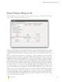
Material
& Structure
Analysis Suite
Z-cracks manual and tutorial
Version 8.6
Z-set 8.6 is distributed by
Transvalor S.A.
Centre des Matériaux
B.P. 87 Ð 91003 EVRY Cedex
France
http://www.zset-software.com
[email protected]
Neither Transvalor, ARMINES nor ONERA assume responsibility for any errors appearing in this
document. Information provided in this document is furnished for informational use only, is subject
to change without notice, and should not be construed as a commitment by the distributors.
Z-set, ZebFront, Z-mat, Z-cracks and Zebulon are trademarks of ARMINES, ONERA and Northwest
Numerics and Modeling, Inc.
c
ARMINES
and ONERA, 2015.
Proprietary data. Unauthorized use, distribution, or duplication is prohibited. All rights reserved.
Abaqus, the 3DS logo, SIMULIA, CATIA, and Unified FEA are trademarks or registered trademarks
of Dassault Systèmes or its subsidiaries in the United States and/or other countries.
ANSYS is a registered trademark of Ansys, Inc.
Solaris is a registered trademark of Sun Microsystems.
Silicon Graphics is a registered trademark of Silicon Graphics, Inc.
Hewlett Packard is a registered trademark of Hewlett Packard Co.
Windows, Windows XP, Windows 2000, and Windows NT are registered trademarks of Microsoft
Corp.
Contents
Reference manual
Introduction . . . . . . . . . .
Import/Export/Hotspots tab
Cracks tab . . . . . . . . . . .
Insertion tab . . . . . . . . .
SIF tab . . . . . . . . . . . .
Propagation tab . . . . . . .
Advanced tab . . . . . . . . .
External tools . . . . . . . . .
.
.
.
.
.
.
.
.
1.1
1.3
1.7
1.11
1.13
1.17
1.21
1.25
1.27
Tutorial
Elliptical crack in an infinite medium . . . . . . . . . . . . . . . . . . . . . .
Turbine disc failure . . . . . . . . . . . . . . . . . . . . . . . . . . . . . . . .
Turbine blade failure . . . . . . . . . . . . . . . . . . . . . . . . . . . . . . .
2.1
2.3
2.9
2.15
Scripting manual
Scripting informations
Global variables . . . .
Functions . . . . . . .
Scripting file example
3.1
3.3
3.5
3.9
3.11
.
.
.
.
.
.
.
.
.
.
.
.
.
.
.
.
.
.
.
.
.
.
.
.
.
.
.
.
.
.
.
.
.
.
.
.
.
.
.
.
.
.
.
.
.
.
.
.
.
.
.
.
.
.
.
.
.
.
.
.
.
.
.
.
.
.
.
.
.
.
.
.
.
.
.
.
.
.
.
.
.
.
.
.
.
.
.
.
.
.
.
.
.
.
.
.
.
.
.
.
.
.
.
.
.
.
.
.
.
.
.
.
.
.
.
.
.
.
.
.
.
.
.
.
.
.
.
.
.
.
.
.
.
.
.
.
.
.
.
.
.
.
.
.
.
.
.
.
.
.
.
.
.
.
.
.
.
.
.
.
.
.
.
.
.
.
.
.
.
.
.
.
.
.
.
.
.
.
.
.
.
.
.
.
.
.
.
.
.
.
.
.
.
.
.
.
.
.
.
.
.
.
.
.
.
.
.
.
.
.
.
.
.
.
.
.
.
.
.
.
.
.
.
.
.
.
.
.
.
.
.
.
.
.
.
.
.
.
.
.
.
.
.
.
.
.
.
.
.
.
.
.
.
.
.
.
.
.
.
.
.
.
.
.
.
.
.
.
.
.
.
.
.
.
.
.
.
.
.
.
.
.
.
.
.
.
.
.
.
.
.
.
.
.
.
.
.
.
.
.
.
.
.
.
.
.
.
.
.
.
.
.
.
.
.
.
.
.
.
.
Chapter 1
Reference manual
Z-set — Non-linear material
& structure analysis suite
1.1
1.2
Z-set — Non-linear material
& structure analysis suite
Introduction
Introduction
A new module called Z-cracks has been released in Z-set version 8.5. This tool provides a
generic and efficient framework for 3D cracks studies with both static crack configuration stress
intensity factor (SIF) computation and mixed-mode propagation under assumption of linearelastic fracture mechanics (LEFM) and small deformations. Associated to a specific graphical
user interface (GUI), this module is built on a robust 3D adaptive remeshing technique and
an efficient multi-threaded SIF extraction post-processing.
The present manual provides a review of the abilities of such tool, describing different aspects
related to:
• sane mesh import/export features, crack surface description and multiple cracks insertion
• static crack calculation with SIF and energy release rate outputs
• propagation calculation with simple or user-defined propagation laws for fatigue loading
• advanced aspects: complex multiple cracks, contact, 2D problems, cohesize zone insertion, etc.
In order to start using Z-cracks simply type Zcracks. The Z-cracks window will open: it is
built of many tabs the are linked to the different stages or processes required for crack growth
analysis. The default General tab contains various field that can be described:
Z-set — Non-linear material
& structure analysis suite
1.3
Introduction
• Datafile is the name of the current directory file name that will store all Z-cracks
relevant parameters provided in the GUI
• Editor is used to set the preferred text editor command-line that will be used to edit
the various text files for calculation input and output
• #CPU for SMP is used to set the number of processors that will be used for possibly
multi-threaded phases of the calculation (i.e. material integration, linear solver, SIF
extraction)
• Sane name is used to specify the name of the initial finite element mesh (that could be
eventually imported from an external finite element software), note that such file should
be in the current working directory (as all create files when using Z-cracks) and such
given name must not contain any extension
• Crack name is used to specify a Z-set mesh file (without extension) that describes the
geometry of the crack(s) that will be inserted1
• Cracked name is used to specify the name of the generated crack mesh and the associated
computation files, if default value cracked is used, the generated initial mesh file will be
called cracked.geo, the associated SIF computation input file cracked_SIF.inp and
the crack propagation file cracked_PROPAG.inp
Some parameters are linked to remeshing features and used in every adaptive refinement
processes of Z-cracks. They drive the included Inria remeshing tools that are called in order
to clean and refine produced meshes. Let detail their functionalities:
• Min size specifies the absolute minimal size of the meshed elements with a floating
point value (this min size is applied closely to the crack front)
• Max size specifies the absolute maximal size of the meshed elements with a floating
point value
• Yams options is used to define a string for surface remeshing options (see above note
and the Distene Yams manual)
• Iterations requires an integer value as the number of remeshing iterations (depending
of the initial mesh characteristic size compared to the crack dimensions and a required
Min size value, default is 2 can be increased up to 5 − 10 but it will slow down the
remeshing process)
• Curvature refine is used to apply an adaptive mesh coarsening relative to the crack
front curvature. When the front is highly curved, the Min size is applied, elsewhere
the element size can grow up to 32 times this base value.
• Gradation is a value used to set the mesh coarsening speed when the distance to crack
front increases (usually this value can be set to 1.3 for linear meshes, and to 2.3 for
quadratic).
1
such mesh file (named crack for instance) must contain a shell based 3D mesh (better with triangular
based elements) and an elset named crack containing all surface elements, a nset called crack containing
its nodes and a liset named crack front that contains all the cracked surfaces unshared edges (its boundary
that will generate the crack front). Such file can be obtained from a specific mesh that is built elsewhere (for
complex predefined geometries), of using the Z-cracks GUI for (multiples) penny shape or elliptic shape cracks.
1.4
Z-set — Non-linear material
& structure analysis suite
Introduction
Let give some information about usual Yams options commands that could be useful (see
the Distene Yams manual for an exhaustive description):
• -m XXX is used to set up memory amount in MiB that will be allocated during the
remeshing (default value is 500MiB)
• -FEM indicates that a suitable mesh for finite element computation must be generated
• -Dridge=xx is used to specify an angle in degree (floating point value) that will be
used for ridges detection, lower values detects more ridges (default value is 45., can be
deactivated using -nr)
• -Dgradation=xx is used to specify the maximal neighbour edges length ratio (defined as
> 1), small values produces surface mesh with a smoother transition between thin and
coarse elements (default value is 1.3), note that such action doesn’t have any influence
on the adaptive remeshing volume algorithm (thus a high value like 10. is a good choice
for 3D meshes as it shows on the surface what will happen in the volume)
• -Dgeomapp=xx and -Dtolerance=xx can be used to coarsen or refine the geometric
approximation meshing of surfaces (using floating point values value from .001 for fine
meshes up to 10. for coarse ones, see the Distene manual for more details)
The Save button is used to write the datafile that stores all field contents and options of
the GUI using the name set in the Datafile field. In fact for almost every meshing and
calculation operations (called pressing any of the associated buttons) an automatic saving is
done.
The Open button is used to open a previously written Z-cracks datafile using the named set
in the Datafile field.
The Quit button is used to exit the Z-cracks toolbox.
The next pages will describe the functionalities provided in each tab following a usual crack
propagation study main stages:
1. importing the mesh, if required (and possibility exporting the cracked one), thus performing hotspot calculation for critical point localisation and initial cracks definition
2. building the initial crack meshes
3. inserting the cracks in the current mesh and processing the adaptive remeshing
4. performing static SIF or energy release rate computation
5. performing crack propagation study
6. using efficiently associated tools
Z-set — Non-linear material
& structure analysis suite
1.5
Introduction
1.6
Z-set — Non-linear material
& structure analysis suite
Import/Export/Hotspots tab
Import/Export/Hotspots tab
Note that this stage can be skipped if a Z-set initial sane mesh is available for the analysis
and no initial crack position must be guessed.
This tab concerns the way to import any mesh that comes from Abaqus (.inp), Salome (.med)
or Inria (mesh) formats. It also allows to perform surface detection, mesh coarsening or
refinement, scaling and insures exportation feature of any cracked mesh generated by the
tool.
The second part of the dialogue box is dedicated to hotspots analysis: for simple problems
critical points can be identified on a uncracked FEA. Such an approach is based on non-local
maximal Von Mises criterion identification to extract a certain number of critical point (the
non-local aspect is set to insure that a possible maximum must contain the highest Von Mises
equivalent stress value compared to any possible point inside a given radius). Such point are
then ordered and only a prescribed number will be displayed. For all such points, an eigenstate
decomposition is proceeded in order to specify that a possible crack initiation can occur only
if a traction state is been observed for the absolute highest principal value. In such a case,
an associated initial crack dataset will be generated as the definition of a disc of a specified
radius, centred on the critical point position, and oriented normally to the highest eigenvalue
associated eigenvector. Such an operation is been carried out as a post-processing analysis
on the uncracked FEA solution, if multiple time solutions are given the critical points will be
ordered along the whole time interval and the associated crack dataset will be generated only
for the most intense stress condition.
Z-set — Non-linear material
& structure analysis suite
1.7
Import/Export/Hotspots tab
Concerning the export/import features, tab fields functionalities are:
• Import format is used to set the import/export format (must be among abaqus for
Abaqus .inp file, med for Salome mesh files and mesh for Inria .mesh files import only)
• Scale factor gives a floating point parameter as a scale factor (applied during import
and reverted during export) useful as Z-cracks parameters are always linked to absolute
values
• Get surfaces gives a floating point angular criterion (in degree) that will be used to
call extract_surface (see user manual) mesher after mesh importation (only if not
null), to extract the input mesh ridges and continuous surfaces separated by detected
ridges
Concerning the export/import features, here are check box functionalities:
• Quadratic mesh is used to set that the imported mesh is quadratic (it will be converted
to linear, native quadratic meshes cannot be kept during crack processing - but quadratic
computation is always possible)
• Remesh after input is used to call a remeshing process just after the importation
Yams options will thus be interpreted
• Fuse during remeshing is used to activated a fuse_nset mesher (see user manual)
with a standard tolerance (set using the Mesher.Meshfusion global parameter).
• Surface mesh is used to specified that the imported mesh is only a “skin” mesh and
must not be filled using the tetrahedral automatic mesher (i.e. for a 2D problem)
• Volume meshing only specifies that only the volumetric tetrahedral mesher will be
called
Concerning the export/import features, buttons functionalities are:
• Import processes the importation process and generate a Z-set mesh file called Name.geo
• Export exports the crack mesh in the external format using the name specified in the
Cracked name global tab
• Medit opens the lastly remeshed surface mesh using medit (if available), such button
exist in various tabs and keeps the same functionality
• Zmaster opens the imported generated mesh in Zmaster
• ParaView opens the imported generated mesh in Paraview (if available)
Concerning the hotspot research feature, tab fields functionalities are:
• Number is to specify the number of critical points that can be searched at each time
increment of a FEA (but a lower number can used for initial crack dataset generation
as only traction states will be kept)
1.8
Z-set — Non-linear material
& structure analysis suite
Import/Export/Hotspots tab
• Zone radius gives a floating point parameter as radius which will be used to define
a sphere at each possible maximum point, only if this current point get the maximum
value among all other values at each node of the mesh inside such sphere, this point will
be kept as critical (is is useful to reduce the number of “fake” maxima due to numerical
noise - such value should be set as a few time the length of the characteristic meshed
element size)
• Init radius gives a floating point value as the initial cracks size (considering a penny
shaped crack) that will use to generate the dataset of crack geometries at each critical
point
Concerning the hotspot research feature, buttons functionalities are:
• Generate .inp is used to generate a Z-set calculation input file for hotspot analysis
that must be filled with the user defined conditions (note that if an abaqus calculation
file has been previously imported a copy of such file used)
• Edit .inp opens the hotspot analysis input file in the specified text editor
• Compute starts the FE solution process of the user defined uncracked problem, followed
by a post-processing analysis that will search the critical point on the obtained solutions
• PostProcess runs only the post-processing analysis, a suitable solution must has already
been computed (very if only hotspot related input has changed since the FE solution
has been obtained has the post processing is usually very fast compared to solution
computation)
• Zmaster opens the Zmaster GUI to graphically analyse the FE solution
• Paraview opens the Paraview GUI to graphically analyse the FE solution (if available)
Z-set — Non-linear material
& structure analysis suite
1.9
Import/Export/Hotspots tab
1.10
Z-set — Non-linear material
& structure analysis suite
Cracks tab
Cracks tab
Note that this stage can be skipped if a suitable crack surface was previously generated with
another tool (see the introduction 1 footnote about the standards that such surface mesh must
observe), for convenient conversion see the Convert functionality in this tab.
In this tab, simple shaped crack surfaces can be generated: single or multiple cracks geometries
can be meshed in order to be inserted into a numerical model. Currently, crack geometry can
be disc or plain ellipse that will create discontinuities when intersected with the sane structure
mesh.
For multiple cracks, it is needed to process incrementally: defining the first surface with
id = 0, pressing the Run button, then setting id = 1, giving information and pressing Run
once again, until all required crack geometries are defined.
In order to modify a previously defined surface it is needed to specify its id in Surface id
and then to press button Load in order to restore its related parameters in the GUI. When
modified press button Run to perform mesh generation and save the crack surface parameters.
When finished it is necessary to set Surface id to the final crack surface id, press Load and
Run to build the final mesh with all the updated crack surfaces. In fact, with a value set in
surface id, pressing Run button process the current id surface meshing operation and join
it to all the lower id cracked meshes (if present).
Note that intersecting or very close multiple cracks cannot be inserted directly in a sane mesh
as the cutting process will probably fail (in such situation, it is required to insert separately
each crack surface).
Z-set — Non-linear material
& structure analysis suite
1.11
Cracks tab
Tab fields functionalities are:
• Surface id is used to set an integer number to identify the current surface (it is used for
multiple cracks starting from 0 for a single crack, up to n for n+1 crack surfaces), if button Verb is pressed the parameters used to built the specified crack surface imperviously
meshed are loaded in the GUI
• Center requires 3 floating point numbers for the 3D coordinates of the position of the
surface center
• Normal requires 3 floating point numbers for the 3D coordinates of the crack surface
normal
• Radius requires a floating point value of the radius of the disc (or the first axis length
in the given direction for an ellipse)
• Direction requires 3 floating point numbers for the 3D coordinates of the first axis
direction of an ellipse (if selected, note that normalisation with the above given surface
normal will be applied)
• Ortho/dir radius specifies the radial length in the orthonormal direction for an ellipse
with a given floating point value
• Surface mesh can be used to convert a user defined crack surface (made of Z-set shell
elements into a surface possibility inserted using the toolbox). Type the correct mesh file
name and press the Convert button (do not press Run that would replace the converted
crack mesh by a generated penny shape crack)
Here are check box functionalities:
• Ellipse specifies that a plain ellipse must be built instead of a simple disc.
• Mesh with CZM elements specifies that cohesive elements shall be inserted in the crack
surface (Min size value is then imposed on the whole surface)
Buttons are used to:
• Load load the previously generate crack surface information specified by the id value
• Run generate the current surface mesh and include all the lower id crack surfaces
• Run all generate all the predefined surface mesh from id 0 to the current id value (very
useful if multiple cracks dataset has been previously generated, for instance using a
hotspot analysis)
• Medit opens medit (if available), to visualise the generated crack surface meshes (added
to the sane mesh if Sane name is already set)
• Zmaster opens Zmaster, to visualise the generated crack surface meshes (added to the
sane mesh if Sane name is already set)
• Paraview opens Paraview (if available), to visualise the generated crack surface meshes
(added to the sane mesh if Sane name is already set)
1.12
Z-set — Non-linear material
& structure analysis suite
Insertion tab
Insertion tab
This tab is used to drive the mesh refinement an crack insertion process on the initial sane
mesh. It constitutes the heart of the crack meshing process. Two stages are required: in
the first one the given sane mesh is remeshed closely to the crack surfaces (possibly a zone is
extracted in this area and only such part is remeshed - insuring a conform interface, preserving
its exact topology - pyramid element can be automatically inserted to link hexahedral elements
with tetrahedral ones in the remeshing zone). In the second stage, the crack is inserted using
a robust surface with volume intersection algorithm and an adaptive remeshing process is
applied. Note that insertion could fail due to badly set remeshing parameters (see details
about Yams options in the main tab manual).
Tab fields functionalities are:
• Elsets specifies the names of all the elsets that must be preserved during the remeshing
process (separated by a space)
• Fasets specifies the names of all the fasets that must be preserved during the remeshing
process (separated by a space)
• Lisets specifies the names of all the lisets that must be preserved during the remeshing
process (separated by a space)
• Ridges specifies the names of all the ridges that must be indicated to the remeshing
process (separated by a space)
Z-set — Non-linear material
& structure analysis suite
1.13
Insertion tab
• Nsets specifies the names of all the nsets that must be preserved during the remeshing
process (separated by a space) - be aware that nset preservation is only guaranteed for
corners nodes (lines or surface preservation must be insured using liset and fasets). Note
that if a nset is required during the calculation and is not found among available nsets,
the nodes from a bsets with the same name will also be searched
• Elset radius requires a floating point value: if strictly positive, it defines a distance
that will be used to extract all the elements that contains at least one node that is
closer to the crack surface than the prescribed distance (only such elements will be
remeshed during the process an reintroduced in the final mesh insuring an exact topology
preservation of the interface), active only if Must extract elset is checked
• Quad radius is a floating point parameter related to a maximal distance from the crack
fronts under which quadratic interpolation can be used (only active if strictly positive
and when Quadratic mesh is activated)
• Thickness is used to treat 2D problem performing an extension, if default integer value
0 is specified, a 3D problem is considered, otherwise the number of layer extensions can
be set and then the thickness of each one given (i.e. filled with “3 .1 .2 .5” will produce
an extension with 3 layers of thickness .1 .2 and .5)
Here are check box functionalities:
• Must extract elset is used to specify that only the given Cracked elset (see Advanced tab) will be remeshed or the sub-part defined by Elset radius
• Moving elset is used to specify that, if the option Must extract elset, is activated,
inside the prescribed Cracked elset given Advanced tab) only the sub-part defined
by Elset radius that is close enough to each crack front will be remeshed during the
overall crack propagation
• Quadratic mesh is used to impose a quadratic interpolation of the generated cracked
mesh possibily restrained to the elements close enough to the cracks front using prescribed distance Quad radius (for the entire mesh if such value is set to 0)
• Quarter nodes is used to impose that on the crack front Barsoum’s quarter-node elements will be applied (must be deactivated for elastic-plastic cracks)
Buttons are used to:
• Run refine first stage of the insertion process: refines the mesh closely to the crack
surface and possibly extracts a sub-mesh (visualisation of the refined zone can be checked
by pressing the button Medit)
• Run cut second stage and last stage of the insertion process: cuts the refined mesh
and generate the complete cracked mesh (visualisation of the remeshed cut zone can be
checked by pressing the button Medit)
• Medit opens medit (if available), to visualise the last generated remeshed domain
• Zmaster opens the initial sane mesh in Zmaster
• ParaView opens the initial sane mesh in Paraview (if available)
1.14
Z-set — Non-linear material
& structure analysis suite
Insertion tab
• Kill kills the current remeshing process task (a too long remeshing process means badly
chosen parameters: remeshing time is usually about 10s up to 100s for 10 000 nodes up
to 1 000 000 nodes generated meshes, on a 2011 laptop)
Z-set — Non-linear material
& structure analysis suite
1.15
Insertion tab
1.16
Z-set — Non-linear material
& structure analysis suite
SIF tab
SIF tab
Using this tab the FE solution of the current cracked structure solution will be computed
and post-processed to calculate energetic crack parameters. It constitutes the crack analysis
toolbox. Here SIF computation and energy release rates computation can be carried out using
a G − θ approach, the process is multi-threaded using the number of processes specified in
the main window. Two branching criteria can be used to predict the suitable propagation
direction that will be chosen by the advancing crack:
• the first one is based on the SIF extraction (obtained from an integration integral using
the Westergaard analytical solutions), a maximal opening stress criterion is then used:
if the extracted stress intensity factor value in mode II KII is sufficiently high compared
to mode I value KI , the branching angle α is computed as:
!
p
−KII /KI + (KII /KI )2 + 8
α = 2 arctan
(1)
4
This criterion, is very fast to get the branching direction but can only be used for
homogeneous isotropic materials
• the second one, is based on two computations of the energy release rate value in two
orthogonal directions. The first one, is along the tangential crack direction is gives a
Z-set — Non-linear material
& structure analysis suite
1.17
SIF tab
value called GI , the second one in the orthogonal direction produces a second value
called GII . The chosen branching angle for the new propagation direction is set to
be atan2(GII , GI ) value. Such an approach is not based on rigorous mechanical consideration as the usual branching criterion, however numerical assessment shows that
it predicts efficiently complex mixed mode propagation crack path when a sufficiently
small discrete propagation step is imposed (even for none isotropic or homogeneous
materials).
Finally for the chosen applied criterion the optimum energy release rate is computed based
on a general G − θ approach, and a mode I Irwin formula is used to produce an equivalent KI
stress intensity value.
To obtain precise SIF values (with an error level lower than 1%), some advices can be made:
• use default values for Front nodes and advanced Refine factor, Element layers
parameters
• always prefer a quadratic mesh to a very fine linear one
• obtained values closely to the structure surface for opened front are really hard to get
precisely
• always proceed a convergence analysis as the remeshing process is very fast, Zcracks’interface is particularly adapted to this analysis since only the Min size value has
to be reduced (control the mesh quality with Medit, see the tutorial about it and eventually increase the number of remeshing Iterations), loop until the distance between
two successive plotted curves be under your targeted error level
If a correct convergence analysis has been performed it can safely be kept for crack propagation
as crack front size will increase and produce even better SIF results (it is even possible to
increase automatically the Min size value accordingly to the crack front extension, but this
must be done with caution).
For all gnuplot visualisation the horizontal axis value is the arc length position along the crack
front starting form the first node of the associated crack front liset (position can be seen using
the text editor ascii datafile pressing the G/SIF values button).
Tab fields functionalities are:
• Front nodes requires an integer value, used to specify the number of point where energetic values will be computed if strictly positive; if equals zero, a value will be computed
for each node of the meshed crack fronts (that will produces oscillations in the result due
to numerical integration difficulties); if negative a value will be computed every −value
nodes that is used to regularize the obtained values (default is −8, it could usually be
chosen from −2 up to −16 depending of the mesh refinement)
• Front# requires a integer value used for gnuplot visualisation specifying the front id
(that is different from the crack surface id, expect for single crack front when value
must always be 0)
Here are check box functionalities:
• Compute SIF imposes that the quantity of interest be an equivalent SIF value instead
of the default energy release rate value (it also has influence on the quantity given to
1.18
Z-set — Non-linear material
& structure analysis suite
SIF tab
the crack propagation law that must be set in G or K). Be aware that the equivalent
SIF is computed using the isotropic linear behaviour evaluated on the crack front for
any kind of material and only has a meaning for isotropic homogeneous material (G is
more general)
• Interaction integral is used to activate the interaction integral branching criterion
(faster) but less general than the vectorial G default one
• Out plane propagation is used to specify that a branching direction must be searched
(useful for mixed mode loading)
• Smooth opened front is used to set that interpolation of the inside volume values will
be used closely to the structure surface for opened front instead of the computed surface
one (which is hard to get properly), this could be a good choice when a very fine crack
meshing has been done in order to obtain smoother results during the propagation
process
• Lips contact is used to take into account lip contact imposing a small deformation
non penetration condition in the same way as what is done with CZM. If penetration
is detected a penalization term will be imposed (such a solution is very fast for usual
fatigue loadings, but requires an updated Newton-Raphson p1p2p3 non-linear algorithm
and usually achieves convergence within about 3 to 5 iterations)
Buttons are used to:
• Generate .inp is used to generate a pre-filled Z-set input calculation file ready for
Z-cracks, that must be completed to address the user’s problem
• Edit .inp is used to edit the Z-set input file using the specified text editor (adding
boundary conditions, materials, etc.)
• Compute runs the calculation using the prescribed number of threads
• Zmaster opens Zmaster to analyse the calculation results
• ParaView opens paraview (if available) to analyse the calculation results
• G/SIF values displays the SIF or G values in the created datafile using the specified
text editor
• Plot G displays the G and optimal G curve along the specified crack front using gnuplot
(if available)
• Plot SIF displays the modes I, II, III SIF and the equivalent optimal SIF curve along
the specified crack front using gnuplot (if available)
• Plot Temperature displays the temperature curve along the specified crack front using
gnuplot (if available)
• Plot Branching displays the optimal branching angle curve along the specified crack
front using gnuplot (if available)
• Plot Front displays a 3D curve plot of the specified crack front using gnuplot (if available and Print front value is strictly positive before computation)
Z-set — Non-linear material
& structure analysis suite
1.19
SIF tab
• Kill SIF interrupts the SIF computation task
1.20
Z-set — Non-linear material
& structure analysis suite
Propagation tab
Propagation tab
Using this tab crack propagation simulations can be computed. It constitutes the crack growth
analysis toolbox. Crack propagation currently is restrained to the case of fatigue loading and
to an explicit propagation algorithm. In this section only the case of a Paris relationship will
be considered. The time grid is defined in the calculation input file and linked to the crack
advance scheme defined after an initial pre-load (before Fatigue Ti) by a cyclic loading of a
constant time interval Fatigue DT, whereas the law will be written:
∆a
∆a
= C (Gmax − Gmin )m or
= C (Kmax − Kmin )m
∆N
∆N
(2)
where ∆a is the incremental front advance along the crack front, depending on the activation
of Compute stress intensity factors. Usually a prescribed ∆N =DN value is set, but if
the Max advance value is reached, the fatigue cycle increment will be reduced with possibly
floating point ∆N values. The global algorithm can be described as follows (for energy release
rated based computations), if t >Fatigue Ti:
1. set Gmin = 0, Gmax = 0
2. compute current time increment and keeps extremal G values
3. if mod(t−Fatigue Ti,Fatigue DT) 6= 0 go back to 2
Z-set — Non-linear material
& structure analysis suite
1.21
Propagation tab
4. compute propagation length with ∆N =DN
5. maximal computed front advance is greater than Max advance, reduce ∆N accordingly
6. update N value with ∆N and process remeshing with advanced new crack position
7. go back to 1
Such an algorithm should be applied carefully as no geometrical update and stress state is
considered during fatigue cycle step DN. Thus for highly reliable crack studies Max advance
should be set to the same order as Min size (note that for complex mixed mode only the
branching direction associated to the maximal obtained G value during the loading cycle will
be used). Note that SIF values computed at any required time step are stored in text files
saved in the .zres directory that keep to simulation results.
Tab fields functionalities are:
• Max advance specifies the floating point absolute value of the upper bond of the crack
advance length that can be applied during the remeshing process (for a Paris law it
can reduce linearly the ∆N increment to satisfy such length, for incremental or more
complex propagation laws such length is used to define when the propagation must be
operated: front advance is accumulated in the propagation law and when it becomes
larger than Max advance remeshing process if operated - having thus a great influence
on crack propagation precision) - usually values from 1/10th up to 10th ) of Min size are
used (it can be considerably increased for coarsened faster simulations). If a negative
value is set (ie −x.), it means that advance is proportional to the radius of the integration
domain along the crack front with a factor x (very useful if front advance is scaled)
• Front ini length is a floating point value that must fit the initial cumulated crack
fronts length (used if Scale refinement function during propagation is active, in
order to coarsen or refine the mesh Min size during the propagation to adapt the
mesh refinement if the crack front size varies much), it usually produces more affordable
computation for long crack growth but must be used with caution
• Initial time is the final time of the pre-load that can be applied initially to the studied
fatigue problem, after this initial fatigue time, cyclic loadings will be considered
• Cycle DeltaT is the constant fatigue cycle interval, at the end of which propagation
will be applied considering that DN loading cycles have occured
• C, m are floating point values of the Paris law coefficients (must be set accordingly to
the calculation units depending of mesh size and loading units)
• DeltaN is the explicit increment for the Paris law cyclic integration, can be reduced if
maximal front advance excesses the Max advance value
Here are check box functionalities:
• Scale refinement is used to activate the refinement function adaptation during the
crack growth (see Lip size)
1.22
Z-set — Non-linear material
& structure analysis suite
Propagation tab
• Transfer state is used to activate the unknowns transfer process after remeshing between the old and the new mesh. Deactivating such option can accelerate the simulation
process for LEFM computations but a the incremental loading is applied must be defined
accordingly
Buttons are used to:
• Generate .inp is used to generate a pre-filled Z-set input calculation file ready for
Z-cracks, that must be completed to address the user’s problem (adding boundary conditions, materials, etc.)
• Edit .inp is used to edit the Z-set input file using the specified text editor specified
• Compute runs the calculation using the prescribed number of threads
• Medit opens medit (if available) to visualize the latest generated surface mesh (very
useful to follow the crack propagation during the calculation)
• Zmaster opens Zmaster to analyse the calculation results
• ParaView opens paraview (if available) to analyse the calculation results
• Kill PROPAG interrupts crack propagation computation task
• Edit .plw can be used to replace the usual Paris propagation by a more complex
propagation law, editing an associated .plw text file, for instance:
**behavior fatoxflu
*cofe 3.1e-4
*N 100
...
Z-set — Non-linear material
& structure analysis suite
1.23
Propagation tab
1.24
Z-set — Non-linear material
& structure analysis suite
Advanced tab
Advanced tab
This last tab is devoted to advanced Z-cracks functionalities. It can be used by advanced users
for fine tuning; for very accurate SIF computations, debugging, modifying default filtering
values.
Tab fields functionalities are:
• Debug mode is used to activate and set parameters for the debug mode (is set do default
’No’ value usual optimized code is run, if set to ’YES’ value optimized code is run but
intermediate meshes are generated during the propagation phase, finally is ’GDB’ is set,
the debugging version is run with intermediate mesh generation)
• Crack elset defines the name of the elset that will be remeshed, is default value NEW
is kept, the complete mesh will be remeshed or only the given zone during the given
distance
• Refine radius is a required floating point factor that is used to coarsen the mesh due
to its distance from the front (default value is 0.35, it can be reduced to .1 for really
precise analysis or increased to 1. for fast but coarse calculations)
• Element layers requires an integer value used to specify the number of element layers
where prescribed minimal size must be imposed (values from 2 to 5 can be a good choice,
2 is usually nice enough and means that all element located at a distance lower than
Z-set — Non-linear material
& structure analysis suite
1.25
Advanced tab
2×min size from the crack front will have their characteristic size fixed at min size),
note that this value is linked to the volume integration size during the SIF extraction
process
• Max fronts specifies the maximum number of fronts that can be taken into account,
default is 32, it can be increased if necessary
• Face filtering, Global fuse, Lip fuse are floating point values, that should only
be changed by advanced users and specific cases (with help of the hotline)
• Print front requires a floating point parameter used to output the front in a suitable
gnuplot format (it specifies the length of the drawn normal), nothing is if the null value
is set
• Check ext nodes imposes crack front extremities to stay on the structure surface during
propagation (using the Ext step value), else no correction is applied, every front point
advance following the crack front normal direction (eventually corrected by branching
criterion)
• Remesh fronts separately is used to be able to deal with front coalescing correctly
(default value, can be disabled for debugging)
1.26
Z-set — Non-linear material
& structure analysis suite
External tools
External tools
Efficient use of the Z-cracks requires a minimal knowledge of the associated external tools:
gnuplot, paraview and medit.
The gnuplot interface is quite intuitive to zoom, rescale or pick coordinate and an official
documentation can be found online (see http://www.gnuplot.info/documentation.html).
paraview is more complex and requires to refer to the online documentation (see
http://www.paraview.org/paraview/help/documentation.html).
Advanced paraview users will be able to generate nice crack propagation movies (see
http://www.youtube.com/user/OneraMNU/videos for instance).
medit is far less intuitive but can be really useful for efficient complex (re)meshing validation.
When medit is launched, pressing key h will display the software help in the launched terminal.
Let herein describe the most useful commands:
• key c colors the mesh faces
• key e assigns a specific color to each referenced faset
• key g colors each nset, liset and ridges (in red color), this is very useful to identify
degenerated surface elements as they usually contain over-constrained ridges
• key z/Z are used to zoom/unzoom the view
• key b to toggle between dark and light background
• pushing mouse left button allows to rotate the view
• pushing mouse middle button down allows to displace the view
• shift+mouse left button allows to pick up a face and copy information in the terminal
(number, position, nodes, reference color)
• shift+mouse middle button allows to pick up a node and copy information in the terminal (number position, reference color)
Z-set — Non-linear material
& structure analysis suite
1.27
External tools
• key V defines the new view center using the last picked up element
• key r/R removes/allows all last selected object faces sharing the same reference (very
useful to visualise inside the mesh)
• key +/- scales objects (useful to visualise inside the mesh due to the openGL clipping
distance)
• key F1/F2 can be use activate/edit a user defined planar clipping
• key i reinitializes the view to its original position
1.28
Z-set — Non-linear material
& structure analysis suite
Chapter 2
Tutorial
Z-set — Non-linear material
& structure analysis suite
2.1
2.2
Z-set — Non-linear material
& structure analysis suite
Elliptical crack in an infinite m
Elliptical crack in an infinite medium
This simple tutorial is aimed to get used to the Z-cracks toolbox in order to perform a SIF
convergence analysis on a reference problem. This example is built from the Code_Aster
documentation (see http://www.code-aster.org, manual v3.04.110).
The initial structure geometry is given by the cube.geo mesh (it is 1/8 of a parallelepiped
block of 2500 × 1450 × 240 dimensions), where an elliptical crack (with (a, b) = (25, 6) are
the ellipse main axes length) is inserted in the middle (all length units are millimetres). A
vertical traction is imposed and a 1 MPa pressure is applied on both vertical sides.
The main stages that are related to this study are:
• creating the crack surface mesh
• building the crack mesh with a prescribed refinement
• solving the mechanical problem and computing stress intensity factors
• analysing the results and eventually modify the refinement parameters to converge to
the reference SIF values
In such case the reference solution is given by the following function:
"
KI (α) = 4.0680 sin(α)2 +
2 # 14
b
cos(α)
a
(1)
where α ∈ [0; π2 ] is an angular parameter, a and b are the ellipse main axes length (25 and 6
respectively).
Such curve can be plotted running gnuplot and typing both commands
> set xrange[-90 to 0]
> plot 4.0680*(sin(x/180.*pi)**2+((6./25.)**2)*cos(x/180.*pi)**2)**.25
Useful values for solution validation are:
K({0., 45., 90.}) ≈ {1.9929, 3.4690, 4.0680}
(2)
for both crack extremities and the middle node.
This first case will highlight the possibility of using the ”curvature refinement”, now
available in the software. A first study is aimed to show the difficulties to obtain accurate
SIF values, regarding this kind of crack shape closely to the surface where the crack front
curvature is very high compared to its other extremity. Whereas it can be highly sufficient
for simple penny shaped cracks. Finally using the curvature mesh adaptation is used in order
to obtain very high quality result for a limited computational cost.
1. Initialization
In this part global parameters are set in order to correctly model the cracked structure.
• Go to the Raju directory. A mesh file called cube.geo must be present.
• Launch Z-cracks using the Zcracks command
Z-set — Non-linear material
& structure analysis suite
2.3
Elliptical crack in an infinite medium
• In the General tab set Sane name to cube, preferred text editor, and the number
of required threads
2. Crack surface meshing
This part is related to the elliptical crack surface meshing process.
• In the Cracks tab, set the crack surface center to 0. 0. 0.
• Set the Normal to 0. 1. 0., thus the ellipse will be built in the (x,z) plane
• Set Radius to 25. and direction to 1. 0. 0. for the grand axis
• Check Ellipse and set Ortho/dir radius to 6.
• Set Min size in the General tab to 1. and Max size to 100.
• Back in the Cracks tab, press button Run will generate a plane disc that could
be visualised pressing the Medit button (if medit is available), else pressing the
Zmaster button.
3. Generating the cracked mesh
In this part the cracked mesh will be generated.
• Verify that Sane name if set to cube in the General tab.
• In the Insert tab, to preserve fasets Fasets can be set to haut bas gauche droite
fond face
• To preserve nsets useful for body motion elimination during the remeshing, set
Nsets to P000 P100 P010
• For accurate geometrical remeshing, in the General tab, Yams options can be set
to -m 500 -FEM -Dridge=50.
• Min size value can be kept for now
• Back in the Insert tab, press button Run refine and visualise the refined mesh
pressing the Medit button (if medit is avaliable), the mesh should be refined in the
neighbourhood of the cracked zone
• Press button Run cut and visualise the cut mesh pressing the Medit button (if
medit is available)
• You can also verify the cracked mesh pressing the Zmaster button.
4. SIF analysis
Here a SIF computation analysis will be done.
• In the SIF tab,
check
Outplane propagation
Compute SIF,
Interaction integral
• Press the Generate .inp button and Edit .inp after.
• In the text editor complete the input file bc section this way:
***bc
**impose_nodal_dof
P000 U1 0.
P000 U2 0.
P000 U3 0.
2.4
Z-set — Non-linear material
& structure analysis suite
and
Elliptical crack in an infinite m
P100 U2 0.
P100 U3 0.
P010 U3 0.
gauche U1 0.
face U3 0.
**pressure haut
**pressure bas
1. time
1. time
• Run computation pressing Compute
• When finished press the Plot SIF button to visualise SIF plot along front (if
gnuplot is available)
• When finished press G/SIF values to visualise computed datafile
• To compare the computed values versus the reference ones, type the following
commands in a terminal set in the working directory
gnuplot -persist -e "load(’courbe.plt’)"
gnuplot -persist -e "load(’error.plt’)"
two graphical windows will be opened with plots of Z-cracks results versus the
reference solution
5. Convergence attempt
Here a SIF convergence analysis will be tried using quadratic base functions.
• In the General tab modify the meshing Gradation values to a more suitable 2.3
value for better adaptive mesh refinement near the crack vicinity
• In the Insert tab check Quadratic mesh, and press Run cut
• In the SIF tab rerun Compute and compare new values with linear previous ones
(using plot windows update button)
• In the General tab reduce Min size by factor .5, restart cutting process in the
Insert tab and SIF analysis in the SIF tab and compare the obtained values
With a constant mesh size along the crack front it will require a very high number of
unknowns to obtain a close enough KI value near on one part of the structure.
6. Front curvature refinement
For such a shaped crack front, an adaptive curvature refinement can be used.
• In the General tab check the Curvature refine box and set the Min size to .05
• In the Cracks tab press the Run button
• In the Insertion tab press Auto cut to generate a quality verified mesh (wait for
operation to be done)
• In the SIF tab rerun Compute and compare new values with linear previous ones
(using plot windows update button)
• Change back to a linear mesh in the Insertion tab, press Run cut, run the computation and verify that the error is always below 3% with this coarse 60k DOF
calculation.
Z-set — Non-linear material
& structure analysis suite
2.5
Elliptical crack in an infinite medium
This curvature option and a so fine mesh refinement are not always useful to obtain high
quality SIF values: now set the Min size to .5 and restart such
p example, with a simple penny
shaped crack with a radius 25mm (the theoretical KI = 2 σ a/π value is 5.6419).
2.6
Z-set — Non-linear material
& structure analysis suite
Elliptical crack in an infinite m
Z-set — Non-linear material
& structure analysis suite
2.7
Elliptical crack in an infinite medium
2.8
Z-set — Non-linear material
& structure analysis suite
Turbine disc failure
Turbine disc failure
In the following pages a tutorial example of a crack propagation problem will be studied.
The aim is to perform a complete crack study from insertion to propagation with SIF analysis.
1. Crack import
This part is related to the sane mesh importation, starting from a mesh file in Salome
.med format ( is inside uugiven, just put disc in Sane name and set your preferred text
editor in the General tab).
• Go to new directory, copy there the file disc.med
• Launch Z-cracks interface using command Zcracks
• In the General tab set Sane name to disc, preferred text editor, and the number
of required threads (the rest can be skipped if the disc.geo file is already present
in the current directory)
• In the Import tab set format to med leave all other field to their default values
• Press Import then Zmaster to verify the imported mesh, then close the Zmaster
window.
2. Crack surface definition
In this part the initial crack surface will be created.
• In the Cracks tab, set the crack surface center (press the Zmaster struct to open
the sane disc mesh, it is thus possible to pick up a coordinate in the Zmaster
mesh window using “shift+middle click” on a mesh node and copy/past the given
coordinates in the Center field)
• Set the Normal coordinate and specify a radius (a value from .1 to 5. would be
nice)
• Set Min size in the General tab to about 1/20 or the circle radius value
• Back in the Cracks tab, press button Run will generate a plane disc that could be
visualised pressing Medit (if medit is available), else pressing the Zmaster button.
3. Generating the cracked mesh
In this part the cracked mesh will be generated.
• Verify that Sane name if set to disc in the General tab.
• In the Insert tab, to preserve fasets Fasets can be set to center pressure top
flasque x=0 z=0
• To preserve ridges during the remeshing Ridges can be set to edges1 edges2
• To coarsen the mesh and accelerate computations in the General tab,
Yams options can be set to -m 500 -FEM -Dridge=70. -Dtolerance=.3
-Dgeomapp=.3 -Dgradation=10.
• Min size value can be kept for now
Z-set — Non-linear material
& structure analysis suite
2.9
Turbine disc failure
• Back in the Insert tab, press button Run refine and visualise the refined mesh
pressing Medit (if medit is avaliable), the mesh should be refined in the neighbourhood of the cracked zone
• Press button Run cut and visualise the cut mesh pressing Medit (if medit is available)
• You can also verify the cracked mesh pressing the Zmaster button.
4. SIF analysis
Here a SIF convergence analysis will be done.
• In the SIF tab,
check
Outplane propagation
Compute SIF,
Interaction integral
and
• Press the Generate .inp button and Edit .inp after.
• In the text editor complete the input file bc section this way:
***bc
**impose_nodal_dof
flasque U1 0.
flasque U2 0.
flasque U3 0.
x=0
U1 0.
z=0
U3 0.
**centrifugal square ALL_ELEMENT (0. 0. 0.) d2 2000. cycle_load
• Run computation pressing Compute
• When finished press Plot SIF to visualise SIF plot along front (if gnuplot is available)
• When finished press G/SIF values to visualise computed datafile
• In the Insert tab check Quadratic mesh and press Run cut
• In the SIF tab rerun Compute and compare new values with linear previous ones
(using plot or new datafile)
• In the General tab reduce Min size by factor .5, restart cutting process in the
Insert tab and SIF analysis in the SIF tab, until a suitable convergence is achieved
(comparing SIF plots)
• Press the button Zmaster to visualise the converged SIF calculation, close it when
analysis is finished
5. Crack propagation simulation
Here a crack growth analysis will be done.
• In the Propagation tab, set Max advance to the crack radius value (for a fast
coarse propagation)
• Set Front ini length to the initial total length of the crack front(s) (could be
obtained as the sum of max s value in the generated datafile obtained during the
SIF analysis)
• Check Scale refinement and uncheck Transfer state, thus mesh refinement
will be automatically adapted to the crack length and no transfer process will be
applied
2.10
Z-set — Non-linear material
& structure analysis suite
Turbine disc failure
• Press the Generate .inp button and Edit .inp
• In the text editor complete the input file this way:
***resolution
**cycles
*dtime 1. 1.
*increment 1
*ratio automatic 1.e-5
***bc
**impose_nodal_dof
flasque U1 0.
flasque U2 0.
flasque U3 0.
x=0
U1 0.
z=0
U3 0.
**centrifugal square ALL_ELEMENT (0. 0. 0.) d2 1.e6 cycle_load
***table
**cycle cycle_load 0. 1000.
*time 0. 1. 2.
*value 0. 1. 0.
• Use default parameters for everything else, the propagation will be “cracked front
advance” controlled, with an maximal advance corresponding to the initial crack
radius during each remeshing, and the corresponding N number of cycles will be
adapted
• Press Compute to launch the propagation calculation (it will be run until complete
collapse of the disc - when no more crack front exists or computation fails unable
to converge)
• During the calculation, pressing buttons Zmaster/ParaView/Medit let follow the
crack propagation advance, as well as pressing buttons related to SIF analysis
(in the associated tab) shows evolution of energetic crack parameters for the last
computed time step
• Closing Z-cracks window will not interrupt the calculation, Zcracks can be reopened to follow the launched propagation calculation. To stop the calculation
press button Kill in the Propagation tab.
Following figures present various obtained results for a particular case of this tutorial.
Z-set — Non-linear material
& structure analysis suite
2.11
Turbine disc failure
2.12
Z-set — Non-linear material
& structure analysis suite
Turbine disc failure
To go further, other functionalities can be tested:
• rerun the same problem with the other branching criterion
• try to insert a second crack that should intersect with the first one during the propagation (see the Cracks tab reference manual, to set up a new id)
• consider a problem with a more complex loading and even compression (activating
contact and non-linear solution algorithm)
Z-set — Non-linear material
& structure analysis suite
2.13
Turbine disc failure
2.14
Z-set — Non-linear material
& structure analysis suite
Turbine blade failure
Turbine blade failure
In the following pages a tutorial example of a crack propagation problem will be studied. We
will perform a complete crack study from insertion to propagation with SIF analysis. This
time a predefined temperature map will be applied.
Go to the Blade directory. The sane structure mesh is blade.geo, a steady state thermal
model problem is present.
This time, you will be asked to perform by your own a 3D crack propagation simulation. Both
static SIF and propagation input files are already given. A complex (but unrealistic) loading
is been imposed in order to get both traction and compression conditions on each side of the
blade.
The initial mesh is geometrically coarse, thus to prevent difficulties during the adaptive
remeshing process it is recommended to set the Yams options field to:
-m 500 -FEM -Dridge=80. -Dtolerance=4. -Dgeomapp=4.
1. Isothermal analysis with multiple cracks
In the first part, the study of an isothermal problem is considered. Default parameters
for the refinement can be adapted, but you only need to modify what is mentioned in
the following directions.
• Let consider the case of two cracks localized anywhere but one on each side of the
blade. In the Cracks tab, set the Surface id to 0 and press the Zmaster struct
button, look at the mesh and select a point to pick-up its coordinates, fill the
Center field. Set normal accordingly (maybe through the vertical direction), for a
just initiated crack radius can be set to .1 (thus set Min size to 1/20th , ie .005.
Press the Run button. Set the Surface id to 1 and select another point on the
opposite blade side, proceed as previously, and finally press the Run. Visualise the
generated mesh using medit or Zmaster.
• Let produce the initial cracked mesh. This time only the zone close to each front
will be remeshed, thus check Must extract elset and set a positive large enough
value in the Elset radius field (for instance 2.) and perform the crack insertion.
• For the SIF evaluation process, first verify that the following options Compute SIF,
Interaction integral, Outplane propagation and Lips contact are checked.
Read the .inp file, and run the computation. You can analyse the results which
shows that compression occurs alternatively on each crack when the flexion load is
imposed.
• Now proceed to propagation simulation, verify that propagation increment is set
to a large enough value (-4 for instance) in order to fasten the process.
2. Thermal loading conditions
In this part the loading conditions will be modified in order to address a problem with
predefined loading conditions. Let assume that the thermal map won’t be changed due
to the crack propagation. Thus, we only need to update at each time the mesh changes
the temperature map performing a nodal transfer process.
Z-set — Non-linear material
& structure analysis suite
2.15
Turbine blade failure
• The first stage consists in generating a fake temperature map. This can
be done running the thermal.inp steady-state thermal calculation. Type
Zrun thermal.inp and visualise the solution Zmaster thermal.inp. 2 temperature maps will be generated (considered as the low and high temperature maps for
a fatigue loading).
• The next operation is to allow, the cracked structure computations to get temperature map from the sane structure thermal map. Such operation is obtained by the
Z-set input file transfer.inp, if a copy of current cracked mesh is done in the file
current.geo, running Zrun transfer.inp will transfer temperature nodal values
to the current.geo mesh nodes. Let visualise the transferred map and compare
with the original one.
• Now we need to modify the cracked simulation input file. Before starting the
computation, we will run transfer process on the cracked mesh. Add the following
lines under the ****calcul line in the SIF computation file (press the Edit .inp
button in the SIF tab of the Zcracks toolbox:
***shell cp -f cracked.geo current.geo
***shell Zrun transfer.inp
this will copy the initial cracked mesh in the current mesh file and run the transfer
process.
• Now we need to apply the thermal loading in the input file, in the editor add the
following lines:
***parameter temperature
*node
*rec_size -2
0. file current.node 1
1. file current.node 2
2. file current.node 2
3. file current.node 2
Note that *rec_size -2 means that two maps are present in the given current
file.
You can now launch the computation and compare the obtained results with the
isothermal case.
• For the crack propagation, input file need to be adapted as well. Add the following
lines under the ****calcul line in the SIF computation file (press the Edit .inp
button in the Propagation tab of the Zcracks toolbox:
***shell cp -f cracked.geo current.geo
***shell Zrun transfer.inp
followed by: ***parameter temperature
*node
*rec_size -2
*cycle_conversion 0. 1000. 4.
function 0.+4.*cycle; file current.node 1
function 2.+4.*cycle; file current.node 2
function 3.+4.*cycle; file current.node 2
function 4.+4.*cycle; file current.node 2
that will generate the thermal loading condition for all the cycles.
2.16
Z-set — Non-linear material
& structure analysis suite
Turbine blade failure
Update the map file after the remeshing process, near the end of the file after the
line%***Zcracks*** add:
**shell cp -f REMESHED.geo current.geo
**shell Zrun transfer.inp
You can now launch the computation and compare the obtained results with the
isothermal case.
Z-set — Non-linear material
& structure analysis suite
2.17
Turbine blade failure
2.18
Z-set — Non-linear material
& structure analysis suite
Chapter 3
Scripting manual
Z-set — Non-linear material
& structure analysis suite
3.1
3.2
Z-set — Non-linear material
& structure analysis suite
Scripting informations
Scripting informations
This part of the manual of Z-cracks is focused on advanced functionalities based on the
z7p scripting language. A basic description of the available commands to process highly
personalized scripts for crack meshing functionalities is given.
A Z-cracks script is an ASCII text file of extension .z7p, which is built respecting a close to
C language syntax. It should always include the basic Z-cracks functions and have a structure
similar to:
#include <Zcracks_base.z7p> Include basic Zcracks functions
int main() Function that will be executed when the script is launched
{
init_var(); Initialization of Zcracks global variables
... Commands
}
To get familiar with this kind of syntax, one can have a look to the zLangage description
in the developer manual, be aware that zLangage is very case sensitive (syntax differs for
double and int variable assignment, for instance).
To launch the script entitled mesh_crack.z7p just run the following command in a terminal:
Zrun -zp mesh_crack.z7p
Z-set — Non-linear material
& structure analysis suite
3.3
Scripting informations
3.4
Z-set — Non-linear material
& structure analysis suite
Global variables
Global variables
The following lines first describe the global variables used in Z-cracks.
Global STRING variables related to the file names:
• crack_name name of the crack surface mesh (without .geo)
• sane_name name of the initial uncracked mesh (without .geo)
• cracked_name name of the final initial mesh (without .geo)
Global STRING variables related to groups preservation during remeshing (add as many group
names as required, separated by a space character):
• elset_names names of the volume element groups to be kept.
• faset_names names of the surface element groups to be kept (group of faces).
• liset_names names of the segment element groups to be kept (group of lines).
• nset_names names of the nodal groups to be kept (better use liset or faset if possible).
Let now describe the global variables related to the remeshing process.
• [STRING] yams_options parameters added to the yams command line (see the Reference manual introduction for details).
• [double] filter_tol filtering tolerance for meshing operations (usually set to 1.e-6.
• [double] grid_max for exact number truncation in the meshing operations (every mesh
point is set to a grid of resolution grid_max×2−54 for better degenerated cases detections), usually set to 1.e11.
• [double] gradation is a gradation remeshing parameter used in the explicit adaptive
refinement near the crack front (usually set to 1.3 for linear meshes and 2.3 for quadratic
meshes, default is 1.3).
• [double] elset_radius is a distance to front to only apply the adaptive remeshing in
the elements close to the crack surface or the crack front (for crack growth), only active
if if_must_define_elset is zero.
• [double] min_size specify the minimal element edges length (applied near the crack
front).
• [double] max_max specify the maximal possible element edges length.
• [double] lip_factor is used to indicate the initial crack front length for refinement
function scaling during the propagation (activated using the vriable if_lip_factor).
• [int] nb_iter number of iterations for the remeshing process (default is 2).
Z-set — Non-linear material
& structure analysis suite
3.5
Global variables
• [int] nb_velem number of element layers close to the crack front which size should be
fixed to min_size (default is 3).
• [int] if_quad specifies that the mesh is quadratic (all remeshing operations are done
on a linear mesh and conversion is done one purpose - default is 0).
• [int] if_barsoum imposes quarter node elements if quadratic elements are used, near
the crack front (WARNING: must be deactivated for elastic-plastic cracked structure,
default is 1).
• [int] if_must_define_elset is used to impose that only a part of the mesh well be
refined (default is 0).
• [int] if_var_refine is used to impose a variable mesh size will be set along the front
due to the crack front curvature (WARNING: must be applied only if a variable G-theta
support domain along front is implemented for accurate SIF extraction, default is 0).
• [int] if_czm is used to insert cohesive zone elements on the crack geometry an apply
a uniform refinement on the complete surface (default is 0).
• [int] if_remove is used to suppress elements that are not able to be associated to
before remeshing mesh, can be deactivated for boolean operation for instance (default
is 1).
• [int] if_refine_only is used to specify that only a refinement operation is done on
the current mesh (thus is local remeshing on a given elset is perform, the complete mesh
will be rebuilt after the refinement operation, default is 0).
• [int] if_no_open is used to indicate that the cracked surface must not be opened a
the end of the remeshing process (default is 0).
• [int] if_output_surface is used to indicate that the volume mesh generation must
not be applied (useful for intermediate meshing operations, default is 0).
• [int] if_lip_factor is used to indicate that the refinement function must be scaled
to keep a constant number of element along the front(s) during the propagation process
(an initial crack front length must be specified in the variable lip_factor, default value
is 0).
• [STRING] ridge_names names of lisets that must be considerate as ridges during the
remeshing operations.
• [STRING] topo_names names of lisets that must preserve their exact topology during
the remeshing operations (exact segments geometry are preserved).
• [STRING] geom_names names of fasets that must preserve their exact geometry during
the remeshing operations (only works exactly for triangular surface elements).
• [STRING] nset_to_cut names of nset/bset that must be cut (only edges between such
nodes will be cut).
• [STRING] nset_not_to_cut names of nset/bset that must not be cut (any edge that
contains a least one of such nodes won’t be cut).
3.6
Z-set — Non-linear material
& structure analysis suite
Global variables
• [STRING] elset_to_cut names of elset which elements will be cut.
• [STRING] delamin_set names of a bset/nset seed for specific delamination operation
indicate that a delamination zone must be generated starting for this seed and and not
crossing cuting edges (requires a surface mesh).
• [STRING] before_remeshing gives some meshing commands that must be applied before the remeshing operation during automatic remeshing or drive_crack_remeshing.
• [STRING] after_remeshing gives some meshing commands that must be applied after
the remeshing operation during automatic remeshing or drive_crack_remeshing.
• [STRING] optim_style set the optimization style that must be applied with yams (default is ”1”).
Let now describe the global variables required to build elliptical and disc shaped cracks:
• [int] crack_id identify the current elliptical crack surface (0 to crack_id are considerate to exist for multiple cracks problem, default is 0).
• [int] if_ellipse is used to specify that the required crack geometry is an ellipse
instead of a disc (default is 0, penny shaped crack).
• [VECTOR] center is used to specify the center of the required crack geometry to build
(note that set_vector3 function exists to simplify variable assignment, only 3D vector
can be considered).
• [VECTOR] normal is the normal direction of the required crack geometry to build.
• [VECTOR] dir is the direction of the ra length axis for elliptical cracks.
• [double] ra radius of the crack (in the dir direction for elliptical cracks).
• [double] rb ortho-radius for elliptical cracks.
For the mesh import and export feature some global variables can be useful:
• [int] from_quad specify that the original mesh is quadratic and will be converted to
a linear one during the importation process (default is 0)
• [double] scale is used to scale the imported mesh during the importation process,
note that a 1./scale factor is applied during the export process (default is 1.).
Some specific mesh files will be built using Z-cracks and must be reserved to the process
operations. Among those, some files names are required for automatic crack growth adaptive
remeshing.
• TO_REMESH.geo input mesh for crack advance remeshing.
• REMESHED.geo output mesh after crack advance adpative remeshing.
• "cracked_name"_PROPAG.adv ASCII file for automatic crack propagation remeshing
(see the next section for file structure description).
Z-set — Non-linear material
& structure analysis suite
3.7
Global variables
3.8
Z-set — Non-linear material
& structure analysis suite
Functions
Functions
Various functionalities are available in the Z-cracks scripting language to allow almost any
kind of user-specific requirements.
Let detail the functions useful for the importation/exportation/lin to quad features:
• import_mesh(STRING mesh_name,STRING mesh_format) imports the given mesh_name
(without extension) mesh in the Z-set mesh format. mesh_format can be one of
med, abaqus, mesh. Note that mesh is for the Distene .mesh surface mesh file, and if
abaqus is specified a tentative FEM inp file translation will be produced. This command
behavior can be modified by the global variables scale and from_quad.
• export_mesh(STRING mesh_name,STRING mesh_format) exports the given mesh_name
(without extension) mesh to the specified output format.
• convert_quad(STRING mesh_name) converts the current mesh to a linear one if the
global variable if_quad=0, else to a quadratic mesh (if_barsoum is taken into account).
For initial crack surface generation and manipulation:
• [VECTOR] set_vector3(double x,double y,double z) assign x,y and z values to a
3D vector components.
• write_mesh_crack() generates a mesher file for penny shape crack (related to all associated global variables).
• [int] do_mesh_crack(int nowait) runs a previously generated crack mesher (assume
that cracks identify from 0 to crack_id-1 allready exist), if nowait==0 waits for result
and returns an error code if fails.
• convert_surface(STRING surf_mesh_name) converts a given surface mesh to a surface
mesh ready for crack insertion (surface mesh file must be allready in the Z-set format,
use import_mesh function if required, this mesh MUST be linear and made of triangular
elements).
• [int] apply_mesher(STRING in_name,STRING out_name,STRING mesher)
apply
mesher operations on the in_name input mesh (nothing is opened if void) and generates the output mesh out_name.
• [STRING] replace_bset(STRING kept,STRING replaced, STRING transform,
double tol) returns meshing commands that replaces the elements contains in the
bset replaced by a copy of the elements of the bset kept on which transform operation are applied. Thus a fuse operation is done with the tolerance tol (useful for
periodic meshes, must be applied on a surface mesh).
• [STRING] extract_inter_bset(STRING bset,STRING liset) returns meshing commands to extract the liset liset that links the bset bset to the rest of a surface mesh
(useful for conform parallel meshing or periodic conditions preservation).
Z-set — Non-linear material
& structure analysis suite
3.9
Functions
For crack insertion in a given mesh (those commands result highly depends on all the global
variables previously given, especially concerning the names of the required mesh files):
• write_refine_mesh() generates a mesher file for volume adaptive refinement (first
stage of the crack insertion process).
• [int] do_refine_mesh(int nowait) runs a previously generated volume adaptive refinement, if nowait==0 waits for result and returns an error code if fails.
• write_cut_mesh() generates a mesher file for mesh cutting operation (second stage of
the crack insertion process).
• [int] do_cut_mesh(int nowait) runs a previously generated volume cutting operation, if nowait==0 waits for result and returns an error code if fails.
• [double] nice_cut(double mwquality) tries to generate a mesh respecting a worst
element quality criterion (performs both refinement and cutting operations, usually set
mwqualty to 20.). If fails an error is generated, else the worst element quality value is
returned and the reached criterion value is updated.
For advanced crack growth features functions are:
• do_write_adavance_remesh() generates a mesher file to by applied on an input
source TO_REMESH.geo mesh file in order to apply a crack growth controlled by
a "cracked_name"_PROPAG.adv ASCII file and produces an updated output mesh
REMESHED.geo.
The .adv file must respect the following structure and must be user generated when a
crack advance must be applied:
[int] number of fronts, ei 1
To be repeated for each front
[STRING] first front liset name, ei FRONT0
[int] number of control points along the front, ie 4
To be repeated for each control point
[double double double] 3D control point coords, ie 1. 2. 3.
...
To be repeated for each control point
[double double double] 3D control point advance coords, ie -.1 .2 .3
...
...
an example will be presented in the next part of the manual.
• [int] do_drive_remesh(double mwquality) runs and, if the specified value
mwquality is positive, drives the process using a previously generated advance remeshing file. A worst element quality value is required, if the operation fails, a none zero
value is returned.
3.10
Z-set — Non-linear material
& structure analysis suite
Scripting file example
Scripting file example
The following lines presents a Z-cracks scripting file sample:
#include <Zcracks_base.z7p>
int main()
{
init_var();
// Set names
crack_name="crack";
sane_name="cyl";
cracked_name="cyl_cracked";
// Format for conversion
format="med";
// Set meshing options
filter_tol=1.e-6;
grid_max=1.e12;
gradation=1.3;
min_size=4.;
max_size=100.;
nb_velem=3;
if_var_refine=1;
nb_iter=2;
// Uncomment for local refinement only
// elset_radius=50.;
// if_must_define_elset=1;
// Set group preservation
faset_names="surface_0 surface_1 surface_2";
ridge_names="RIDGES";
// Import med mesh
// Add surfaces detection
angle_criterion=45.;
import_mesh(sane_name,format);
// Set geom
if_ellipse=1;
center=set_vector3(0.,0.,0.);
normal=set_vector3(0.,0.,1.);
Z-set — Non-linear material
& structure analysis suite
3.11
Scripting file example
dir=set_vector3(1.,0.,0.);
ra=200.;
rb=30.;
// First crack
crack_id=0;
center[2]=200.;
write_mesh_crack();
do_mesh_crack(0);
// Second crack
crack_id=1;
center[2]=50.;
normal=set_vector3(0.,1.,1.);
dir=set_vector3(1.,1.,0.);
write_mesh_crack();
do_mesh_crack(0);
// Refine and cut mesh respecting a max quality criterion
nice_cut(20.);
// Export
export_mesh(cracked_name,format);
// Propagation example
// using cyl_cracked_PROPAG.adv presented bellow
// Write advance file
do_write_adavance_remesh();
system("cp -f _PROPAG.adv .geo TO_REMESH.geo");
do_drive_remesh();
export_mesh("REMESHED","med");
}
and the associated cyl_cracked_PROPAG.adv is used to produce the meshes shown on the
next pages.
# Automatic driven crack advance
4
FRONT0
4
-9.654060e+01 -2.583730e+01 7.583730e+01
-5.053880e+01 1.895210e-01 4.981050e+01
3.975330e+00 2.770570e+01 2.229430e+01
5.297880e+01 5.000000e+01 0.000000e+00
-1.000000e+01 0.000000e+00 -1.000000e+01
-1.000000e+01 0.000000e+00 -1.000000e+01
3.12
Z-set — Non-linear material
& structure analysis suite
Scripting file example
-1.000000e+01 0.000000e+00 -1.000000e+01
-1.000000e+01 0.000000e+00 -1.000000e+01
FRONT1
3
-96.4116 -26.2503 200.000
10.1438 -29.9211 200.000
96.2994 -26.2325 200.000
0. 0. 5.
0. 0. 6.
0. 0. 2.
FRONT2
2
-96.4540 26.2123 200.000
96.3730 26.2777 200.000
0. 300. 0.
0. 300. 0.
FRONT3
2
-79.3637 -60.9653 110.965
96.7229 25.9496 24.0504
0. 0. 0.
0. 0. 0.
Z-set — Non-linear material
& structure analysis suite
3.13
Scripting file example
Others examples of Z-cracks scripting files can be found in the test database. The
Zcracks2.inp, for instance, performs a crack propagation simulation using a post-processing
coupling (such kind of approach can be applied for an external FE code coupling strategy in
a linear-elastic case without field transfer).
3.14
Z-set — Non-linear material
& structure analysis suite