1
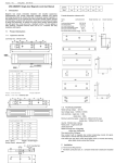
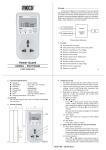
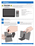
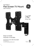
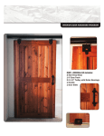
TIP & GLIDE™ WHEEL
INSTRUCTIONS
Carefully read and follow all operational and safety instructions
Tip
Glide
In all applications, except for transporting the ladder, the wheels
must not have contact with the ground.
DO
In stair access position,
keep wheels on the lower
side of stairs (as shown).
DO NOT
Turn ladder outer without wheels 180 degrees and insert lock assemblies
of that base into the adjacent holes of the opposite base. DO NOT have the
wheels touch the ground.
DO NOT have the
wheels on the inside
of the trestle.
Not actual wheel size. Enlarged for demonstration.
DO NOT USE THE WHEELS AS A STEP.
Tools Included:
• Wheel Assembly (2 each)
• Nut, 10-24 Nylock (4 each)
• Screw, 10-24 x 1 1/4 (4 each)
• Wrench, 3/8” Flat (1 each)
• Key, 1/8” Hex Allen (1 each)
• Drill Bit, #10 (1 each)
• Label, Wheel Warning (2 each)
• User Instructions / Warnings (1 each)
Tools Needed:
• Power Drill
• Safety Glasses
ONLY FOR
TYPE IA Models 17, 22, 26 - (2 7/8”)
TYPE IAA Models 17, 22 - (2 7/8”)
TYPE I Models 17 & 22 - (1 7/8”)
2 7/8” Tall
1 7/8” Tall
DANGER
ENSURE THAT THE PROPER FOOT SIZE AND BRACKET
SPACING HAS BEEN DETERMINED. FAILURE TO READ
AND FOLLOW ALL INSTRUCTIONS MAY RESULT IN
INJURIES OR DEATH
Figure 1
1. Unlock ladder and remove one outer
ladder assembly completely off of the
inner ladder assembly.
1 1/4”
2. Take the removed outer ladder assembly
and lay it on flat ground, rung side up.
(Figure 1).
Figure 2A (Type IA, IAA)
3. For Types IA and IAA measure 1/4” (see
Figure 2A); For Type I measure 1¼” (see
Figure 2B) from the top of the rubber
feet on the rung side of the rail and lightly
mark your ladder on both side rails.
Figure 2B (Type I)
1 1/4”
Figure 3A (Type IA, IAA)
Figure 3B (Type I)
4. Then slide the bottom of the wheel
brackets in line with your marks. Make
sure the bottom of the wheel brackets are
¼” (1¼” for Type I see Figure 3B) from
the top of the rubber feet (Figure 3A).
Make sure the bracket slots are flush up
against the edge of the side rail.
5. Use the #10 drill bit to drill two holes into
each of the side rails using the bracket
screw holes as a guide (Figure 4).
6. With the holes drilled, slide in the #10-24
x 1 1/4” screws. Put one 10-24 Nylock
nut on the back of each screw. Use the
wrench to hold the nuts and use the hex
allen key to tighten the top of the screws
(Figure 5).
Figure 4
7. Place the wheel warning labels onto each
side rail. Line them up just above each
foot with wheels (Figure 6).
8. Carefully read all operational and safety
instructions before using the wheels.
Figure 5
Figure 6
©2007 Wing Enterprises, Inc. 51536.2.3