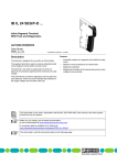
Download IB IL 24 PWR IN (-PAC)
Transcript
IB IL 24 PWR IN (-PAC)
Inline Power Terminal Without Fuse
Data Sheet
5567_en_05
m
AUTOMATIONWORX
© PHOENIX CONTACT - 03/2007
Description
nt
s.
Supply of the 24 V main voltage UM
Supply/provision of the 24 V segment voltage US
Main circuit protected by an external fuse
Segment circuit can be protected by an external fuse
Diagnostic indicator
Approved as power terminal following a safety segment
circuit
Please observe the notes on page 6 when using the terminals following a safety-related
segment circuit.
on
l
in
ec
om
po
This terminal does not have an INTERBUS
protocol chip and therefore is not an
INTERBUS device.
–
–
–
–
–
–
ne
The terminal is designed for use within an Inline station.
The terminal supplies 24 V power to the main circuit (UM).
In addition, this terminal can be used to supply 24 V power
for a segment circuit (US).
co
Features
This data sheet is only valid in association with the IL SYS INST UM E user manual or the Inline system manual
for your bus system.
Make sure you always use the latest documentation.
It can be downloaded at www.download.phoenixcontact.com.
A conversion table is available on the Internet at
www.download.phoenixcontact.com/general/7000_en_00.pdf.
This data sheet is valid for the products listed on the following page.
IB IL 24 PWR IN (-PAC)
Ordering Data
Terminals
Description
Type
Order No.
Pcs./Pkt.
Power terminal without fuse
complete with accessories (connectors and labeling field)
IB IL 24 PWR IN-PAC
2861331
1
Power terminal without fuse,
without accessories
IB IL 24 PWR IN
2726311
1
Accessories
Description
m
One of the listed connectors for the voltage supply is required for the IB IL 24 PWR IN terminal.
Type
IB IL SCN-PWR IN
Connector, colored, for Inline power and segment terminal blocks
IB IL SCN-PWR IN-CP
Documentation
Description
Type
s.
co
Connector, for Inline power and segment terminal blocks
(black, w/o color print);
Order No.
Pcs./Pkt.
2727462
10
2727637
10
Pcs./Pkt.
IB IL SYS PRO UM E
2743048
1
User manual:
"Automation Terminals of the Inline Product Range"
IL SYS INST UM E
2698737
1
DB GB IB IL 24 SAFE 1 (-PAC)
9004913
–
AH EN IL EX ZONE 2
7217
–
Technical Data
General Data
Weight
in
ec
Housing dimensions (width x height x depth)
om
po
Application note:
"Inline Terminals for Use in Zone 2 Potentially Explosive Areas"
ne
Data sheet:
"IB IL 24 SAFE 1 (-PAC) Safety Terminal“
nt
Order No.
User manual:
"Configuring and Installing the INTERBUS Inline Product Range"
12.2 mm x 120 mm x 71.5 mm
44 g (without connectors), 59 g (with connector)
Ambient temperature (operation)
-25°C to +55°C
Ambient temperature (storage/transport)
-25°C to +85°C
Permissible humidity (operation/storage/transport)
10 % to 95 %, according to DIN EN 61131-2
Permissible air pressure (storage/transport)
70 kPa to 106 kPa (up to 3,000 m above sea level)
on
l
Degree of protection
Class of protection
IP20 according to IEC 60529
Class 3 according to VDE 0106, IEC 60536
Connection data for Inline connector
Connection method
Spring-cage terminals
Conductor cross section
0.2 mm2 to 1.5 mm2 (solid or stranded), AWG (24 - 16)
24 V I/O Supply (Main Circuit UM)
Connection
Rated value
+24 V
Ground (GND)
Terminal points 1.2 and 2.2
Terminal points 1.3 and 2.3
24 V DC
Tolerance
-15% / +20%
AC voltage component
5%
Permissible range
19.2 V to 30 V
5567_en_05
PHOENIX CONTACT
2
IB IL 24 PWR IN (-PAC)
24 V I/O Supply (Main Circuit UM) (Continued)
Permissible current
8 A, maximum
Voltage supply requirements
The power terminal must be supplied from a new power supply unit to create
an electrically isolated area. Protect the 24 V area via an external fuse.
The power supply unit must be able to supply 4 times (400%) the nominal current of the external fuse.
Safety Equipment
No
Surge voltage
Yes,
suppressor diode for voltage limitation between terminal points 1.1 and 1.3,
and terminal points 1.2 and 1.3
Polarity reversal
Yes, diode connected in parallel as protection against polarity reversal
m
Overload/short-circuit in segment circuit
co
The power supply unit must be able to supply 4 times (400%) the nominal current of the external fuse.
s.
Electrical Isolation/Isolation of the Voltage Areas
nt
To provide electrical isolation between the logic level and the I/O area, it is necessary to supply these areas via the bus coupler or via the
bus coupler and a power terminal from separate power supply units. Interconnection of the power supply units in the 24 V area is not
permitted. Please also pay attention to GND/PE connections on the power supply units (see also user manual).
ne
Common Potentials
The 24 V main voltage, 24 V segment voltage, and GND have the same potential. FE is a separate potential area.
5 V supply incoming remote bus / 7.5 V supply (bus logic)
7.5 V supply (bus logic) / 24 V supply (I/O)
24 V supply (I/O) / functional earth ground
om
5 V supply outgoing remote bus / 7.5 V supply (bus logic)
po
Separate Potentials in the System Consisting of Bus Coupler/Power Terminal and I/O Terminal
- Test Distance
- Test Voltage
500 V AC, 50 Hz, 1 min
500 V AC, 50 Hz, 1 min
500 V AC, 50 Hz, 1 min
500 V AC, 50 Hz, 1 min
None
Approvals
in
ec
Error Messages to the Higher-Level Control or Computer System
on
l
For the latest approvals, please visit www.download.phoenixcontact.com.
5567_en_05
PHOENIX CONTACT
3
IB IL 24 PWR IN (-PAC)
Local Diagnostic Indicators and Terminal Assignment
Local Diagnostic Indicators
Des.
UM
U M
P W R
IN
Color Meaning
Green 24 V Voltage (main circuit UM)
Function Identification
Black
Terminal Point Assignment
1
1
2 .1
1 .2
2
2
2 .2
3
3
4
4
1 .3
2 .3
2 .4
po
1 .4
1.2, 2.2
nt
1 .1
5 5 6 7 C 0 0 2
The terminal with the appropriate connector
on
l
in
ec
om
Figure 1
Connection of a switch or a jumper in the segmentation level.
Supply points for the main circuit UM
(Main Circuit; +24 V)
Connection of a switch or a jumper in the segmentation level.
These terminal points are connected with each
other and with the potential jumper of the unprotected main supply UM. The potential jumpers of the unprotected main circuit UM and the
segment circuit US have a combined current
carrying capacity of 8 A.
Ground contact (GND)
The reference potential is directly led to the potential jumper and is, at the same time, ground
reference for the main and segment voltage.
FE connection
The contacts are directly connected with the
potential jumper and the FE spring on the bottom of the housing. The terminal is grounded
when it is snapped onto a grounded DIN rail.
Terminal points 1.1, 1.2 and 1.3 are connected
with a capacitor to FE.
s.
2
ne
1
co
m
Terminal Assignment
Point
1.1, 2.1 Supply points for the segment circuit US
(+24 V)
1.3, 2.3
1.4, 2.4
Observe the current carrying capacity
The maximum total current flowing through the
potential jumpers must not exceed 8 A.
5567_en_05
PHOENIX CONTACT
4
IB IL 24 PWR IN (-PAC)
Internal Circuit Diagram
Connection Example
Protect the 24 V supply with an external fuse!
lo c a l b u s
U L
U M
IN
m
P W R
2
co
1
1
2
2
3
3
4
4
+ 2 4 V
(U S )
Key:
5 5 6 7 B 0 0 3
Internal wiring of the terminal points
on
l
Figure 2
in
ec
om
po
+ 2 4 V
(U M )
ne
nt
s.
1
Figure 3
Typical connection of the supply voltage UM
and of an external switch to supply the segment voltage US
To ensure maximum current carrying capacity,
use a power connector to connect the cables
(see "Ordering Data" on page 2).
In these connectors, the adjacent terminal
points 1.2 and 2.2, and 1.3 and 2.3 are jumpered internally.
LED
Most I/O terminals receive their supply voltage
from the segment circuit.
Diode
The switch can be used to create a switched
segment circuit.
Capacitive connection to functional earth
ground (FE)
Other symbols used are explained in the
IL SYS INST UM E user manual or in the Inline
system manual for your bus system.
5567_en_05
5 5 6 7 A 0 0 4
If this is not needed for your application, you can provide
the segment voltage in one of the following ways:
1 Jumper connections 1.1 and 1.2 or 2.1 and 2.2.
2 Supply the segment voltage separately.
3 Use an additional segment terminal.
PHOENIX CONTACT
5
IB IL 24 PWR IN (-PAC)
Notes on Using the Terminals Following a Safety-Related Segment Circuit
Both terminals of the following hardware revision or later
are approved to supply the supply voltage directly after a
safety-related segment circuit.
1
Order No.
Order Designation
2726311
2861331
Hardware
Version
06
00
IB IL 24 PWR IN
IB IL 24 PWR IN-PAC
IB IL 2 4 P W R IN
O rd e r-N o .: 2 7 2 6 3 1 1
M o d u le - ID : X X
H W /S W
0 6 /-
IN T E R B U S
5 5 6 7 A 0 0 6
The hardware version is imprinted on the side
of the housing of every terminal (1 in Figure 4).
Imprinting on an Inline terminal
m
Figure 4
s.
co
The instructions in the current documentation
for the safety terminal must be observed to ensure that the operation of the safety-related
segment circuit is not adversely affected.
ne
nt
Up-to-date documentation is available at
www.download.phoenixcontact.com. It can be
downloaded free of charge.
Approval in Acc. With EG-RL 94/9 (ATEX)
po
Notes on Using the Terminal in Potentially Explosive Areas
II 3G EEx nAC IIC T4 U
om
This Inline terminal conforms to standard EN 50021 and can be installed in a Zone 2 potentially explosive area.
These Inline terminals are Category 3 items of equipment.
UL Approval
in
ec
These Inline terminals for the indicated hardware version or later are suitable for use in
Class I, Division 2, Groups A, B, C, D.
on
l
Before using an Inline terminal in a Zone 2 potentially explosive area, check that the terminal has been approved for installation in this area.
For a list of terminals that are approved for the potentially explosive areas of Zone 2, please refer to the
AH EN IL EX ZONE 2 application note.
Check the labeling on the Inline terminal and the packaging (see Figure 5).
II 3 G E E x n A C IIC T 4 U
P o te n tia l r o u tin g 4 A m a x im u m
fo r u s e in E x a r e a s
IB x IL x x x x x
O rd e r-N o .: x x x x x x x
M o d u le - ID : x x H W /F W
IN T E R B U S
Figure 5
5567_en_05
X X /-
G L
U L
x x
L IS T E D
3 1 Z N
P r o c . C tr l. E q p t. F o r H a z . L o c s .
C l. I, Z n . 2 , A E x n C IIC T 5
C l. I, Z n . 2 , E x n C IIC T 5
C l. I, D iv . 2 , G r p . A ,B ,C ,D T 5
5 5 6 1 B 0 0 1
Example labeling of terminals for use in potentially explosive areas
PHOENIX CONTACT
6
IB IL 24 PWR IN (-PAC)
co
m
Before startup, ensure that the following points and instructions are observed.
1. When working on the Inline terminal, always switch off the supply voltage.
2. The Inline terminal must only be installed, started up, and maintained by qualified specialist personnel.
3. Install the Inline terminals in a control cabinet or metal housing. The minimum requirement for both items
is IP54 protection according to EN 60529.
4. The Inline terminal must not be subjected to any mechanical or thermal strain, which exceeds the limits
specified in the product documentation.
5. The Inline terminal must not be repaired by the user. Repairs may only be carried out by the manufacturer.
The Inline terminal is to be replaced by an approved terminal of the same type.
6. During operation, only Category 3G equipment must be connected to Inline terminals in Zone 2.
7. Observe all applicable standards (e.g., EN 60079) and national safety and accident prevention regulations
for installing and operating equipment.
Restrictions
nt
s.
When using terminals in potentially explosive areas, observe the technical data and limit values specified in the
corresponding documentation (user manual, data sheet, package slip).
Restrictions regarding the Inline system
ne
The maximum permissible current flowing through potential jumpers UM and US (total current) is limited to
4 A when using the Inline terminals in potentially explosive areas.
on
l
in
ec
© PHOENIX CONTACT 03/2007
om
po
The supply of UM and US to the IB IL 24 PWR IN (-PAC) terminal must not exceed 4 A and in each case it
must be executed via the adjacent terminal points.
5567_en_05
PHOENIX CONTACT GmbH & Co. KG • 32823 Blomberg • Germany
Phone: +49-(0) 5235-3-00 • Fax: +49-(0) 5235-3-4 12 00
www.phoenixcontact.com
7


