1
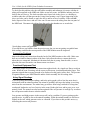
8-Channel Non-Invasive Blood Pressure Monitor NIBP-8 User’s Manual 0219-011M Columbus Instruments 950 NORTH HAGUE AVENUE TEL:(614) 276-0861 COLUMBUS, OHIO 43204, USA FAX:(614) 276-0529 www.colinst.com TOLL FREE 1-800-669-5011 User’s Guide for the NIBP-8 from Columbus Instruments 1 Table of Contents Introduction ................................................................................................................................ 3 Specifications .......................................................................................................................... 3 The Principle of Blood Pressure Measurement .................................................................... 4 Blood Circulation in a Rat’s Tail........................................................................................... 4 Installation .................................................................................................................................. 4 NIBP Device Setup ................................................................................................................. 5 Tail Warming Station Setup................................................................................................... 6 Pre-Experiment Setup ................................................................................................................ 6 Animal Acclimation ................................................................................................................ 6 Experiment Setup ....................................................................................................................... 6 Restraining the Animal .......................................................................................................... 6 Cuff Setup for Rat .................................................................................................................. 6 Sensor Cuff ......................................................................................................................... 6 Occlusion Cuff .................................................................................................................... 7 Cuff Setup for Mice ........................................................................................................ 7 Tail Cradle .............................................................................................................................. 8 Executing the Experiment.......................................................................................................... 8 Preheating ........................................................................................................................... 8 Settings .................................................................................................................................... 9 Pressure Settings ................................................................................................................ 9 Warming Time .................................................................................................................... 9 Scan Settings..................................................................................................................... 10 Starting the Experiment ....................................................................................................... 10 NIBP Software .......................................................................................................................... 11 Sensor Waveform ............................................................................................................. 11 Summary Tab ................................................................................................................... 12 Summary ....................................................................................................................... 12 Notes.............................................................................................................................. 13 Recommendations ....................................................................................................... 13 Markers ............................................................................................................................. 13 Datasheet .......................................................................................................................... 14 Statistics ........................................................................................................................ 15 Datasheet Options......................................................................................................... 15 Channel Tabs .................................................................................................................... 15 The Menus ............................................................................................................................ 16 File .................................................................................................................................... 16 Edit .................................................................................................................................... 16 Setup.................................................................................................................................. 17 Scan ................................................................................................................................... 17 Help ................................................................................................................................... 18 Install Hardware and test the system integrity ........................................................................ 18 Install Hardware and test the system integrity ........................................................................ 19 Figure 1: Tail warmer, the NIBP interface and their connections ................................... 19 Figure 2:Restrainer with a mouse ..................................................................................... 21 Measure tail blood pressure on animal............................................................................. 21 Figures .................................................................................................................................. 22 User’s Guide for the NIBP-8 from Columbus Instruments 2 Guide to using Animal Tail Warmer ................................................................................. 23 Introduction ...................................................................................................................... 23 Installation ........................................................................................................................ 24 To change the heater thermostat temperature setting .................................................... 24 Manual heater Stop and Idle/Monitoring operation....................................................... 24 Error Message .................................................................................................................. 24 Safety heater stop.............................................................................................................. 24 Safety ................................................................................................................................. 24 Troubleshooting........................................................................................................................ 25 Serial Port problems ............................................................................................................. 25 Leakage problems ................................................................................................................. 27 Non-leakage sensor cuff problems ...................................................................................... 28 Connection Problems ........................................................................................................ 28 Functional Equipment Test ............................................................................................... 28 Noisy Signal Readings ....................................................................................................... 28 Tubing Noise..................................................................................................................... 29 Low Pulse Signal Level .................................................................................................... 29 Incorrect Systolic Blood Pressure Readings ................................................................... 29 Cap Unused Channel Connections .................................................................................. 29 Software Problems ................................................................................................................ 29 Program fails to run ......................................................................................................... 29 About ..............................................................................................Error! Bookmark not defined. NIBP-8 .......................................................................................Error! Bookmark not defined. Columbus Instruments ......................................................................................................... 29 Mouse Physiological Data................................................................................................ 30 Rat Physiological Data ..................................................................................................... 31 Last Revised: November 28, 2008 by Ata Sayfee 3 User’s Guide for the NIBP-8 from Columbus Instruments Introduction Columbus Instruments’ NIBP system consists of a microprocessor-embedded control unit and a Windows™ application program. The system acquires the tail artery pulse and corresponding pressure signals through a pressurized sensor cuff during the transition between inflation and deflation of an occlusion cuff. The user can set inflation pressure in both the occlusion and sensor cuffs according to experimental conditions. The NIBP system is capable of measuring blood pressure on up to eight animals. Specifications Applicable Subjects Operating Modes Non-invasive Measurements Range of Measurement Pulse Detection Method Inflation Pressure Data Acquisition Connection between NIBP control unit and computer Power Requirements Fuse Physical Dimensions Weight Rats and Mice Manual and Periodic Scan Systolic blood pressure Diastolic blood pressure Mean blood pressure Heart Rate Blood pressure: Heart rate: Pressurized cuff, palpation Occlusion Cuff: Sensor Cuff: Resolution: Sampling interval: Port: Format: 120-240 volts AC, 60/50Hz, 40 watts 2Amp fast blow fuse 11.5" (W) X 7.5" (H) X 13" (D) 29.2cm (W) X 19cm (H) X 33cm (D) 12 Pounds 5.5 kg 20 ~ 290 mmHg 1 ~ 900 BPM 26 second reading time (10 sec pre-reading, 16 second measurement) 45 ~ 300 mmHg 5 ~ 100 mmHg 12 bits 4 ms RS-232 serial port 19200,N,8,1 User’s Guide for the NIBP-8 from Columbus Instruments 4 The Principle of Blood Pressure Measurement During the inflation of the occlusion cuff, the tail blood will experience three distinct phases. The first phase occurs once the occlusion cuff has been inflated to its user-defined maximum pressure. At this point, the pressure on the artery is so great that it is completely occluded and no blood passes through it. The occlusion cuff then begins to release its pressure. This phase is denoted by the flat-line before the systolic point. The second phase occurs once the pressure in the occlusion cuff drops below the animal’s systolic blood pressure. It is at this time that blood can force its way through the partially occluded artery and generate a signal for the sensor cuff. This phase is represented on the graph by the ascending waveform between the systolic and diastolic points. The last phase takes place when the pressure in the occlusion cuff is not enough to restrict blood flow at all, and the waveform from the signal cuff resumes its regular form and amplitude. Blood Circulation in a Rat’s Tail The presence of continuous blood flow in the tail is crucial in achieving a reliable blood pressure measurement. In a rat’s tail, there are three arteries: two lateral caudal arteries and a middle caudal artery. The middle caudal artery is larger than the lateral arteries. In a rat with the body weight of about 350 grams, its diameter is approximately 700 micrometers. The tail arteries lie along the ventral side of the tail. In a cross sectional view of the rat’s tail, many bundled tendons and a few thin muscles can be seen enclosing these arteries. The tail anatomy suggests that rats do not require a large blood supply for nourishment of their tails. Little evidence of tail blood flow can be seen when the environmental temperature is below 25º C. As the environmental temperature increases from 25º to 28º C, blood flow increases in both duration and volume. Therefore, in addition to nourishment, another physiological function of tail blood circulation has been proposed: a rat may cool its body temperature through relaxing the tail blood vessel. Installation The following items are required to set up the NIBP blood pressure monitoring system: a) b) c) d) e) f) g) h) i) NIBP control unit NIBP install CD (Windows™ compatible) & test results CD (opens thru NIBP software) Power cord Serial communication cables with 9-pin male to female connectors Occlusion and sensor cuff per channel, with occlusion cuff inserts Sets of Tygon tubing, used to connect cuffs to control unit Animal restrainer or unrestrained cage; one for each animal Tail Warming Station (required with restrainers) IBM compatible computer (provided by user) minimum requirement: 133 MHz Pentium® User’s Guide for the NIBP-8 from Columbus Instruments 5 Please contact us if your AC voltage is not 110 ~ 120 V or different from those specified on the back of the control unit. On the front panel of the NIBP control unit there are a Power switch, Power indicator, Rat/Mouse selection switch, and Gain dial. On the rear panel you will find the following connectors: 1. 2. 3. 4. AC power input, it should be plugged into the specified voltage source. Fuse holder (120Vac@2A or 220vac@1A) Use fast blow type fuse) 9-pin female connector for the connection of the control unit to the computer Serial port Depending on the system, 1 to 8 pairs of connectors, occlusion and sensor cuffs should be connected to these ports 5. 9-pin female connector form the control to the Tail Warming Station. The NIBP software is provided on a CD-ROM disk. It is written to operate on a Windows™ based computer. To install the software, insert the setup CD disk into the CD-ROM drive. Depending on the configuration of your computer the installation program starts automatically. If it does not, select the Windows™ Taskbar ‘Start’ button, choose ‘Run’ then browse to the file ‘Setup.exe’ in the root directory of your CD-ROM drive. Alternatively, use Windows Explorer to find the file on the CD-ROM, and then double click the file to install. For best performance, the computer processor should be at least a 133 MHz Pentium®. NIBP Device Setup 1. Install the NIBP software package from the enclosed CD-ROM. 2. Connect the occlusion cuff to the ‘Occlusion Cuff’ outlet port on the back of the NIBP device. 3. Connect the sensor cuff to the ‘Sensor Cuff’ outlet port on the back of the NIBP device. 4. Plug any unused channel outlet ports on the back of the NIBP device. 5. Connect the device to your PC with the serial communication cable. 6. If applicable, connect the NIBP device to the Tail Warming Station with a serial communication cable. 7. Plug the power cord into a proper AC line. 8. Turn on the NIBP device. 9. Run the NIBP software package. 10. If prompted, select the appropriate serial communication port. Any one of the available COM ports can be used. If the port chosen is being used by another program, you will receive an error message. 11. Using the menu, navigate to “Setup” “Check System.” Upon a successful system check, you will receive the message pictured here. If you receive an error message, make sure no other devices are using the communication port or select a new one by navigating to “Setup” “Communication Port.” 12. Once you receive the ‘Device Connected’ dialog, your NIBP unit is setup. User’s Guide for the NIBP-8 from Columbus Instruments 6 Tail Warming Station Setup 1. If you have not already done so, connect the Tail Warming Station to the NIBP device using a serial communication cable. 2. Plug the power cord into a proper AC line. 3. If you are using more than one Tail Warming Station for your multi-channel NIBP unit, daisy chain the warmers together using serial communication cables. Pre-Experiment Setup There are a few things that need to be done some time before the experiment to ensure better results and cooperation from the animal. Animal Acclimation The placement of animals into a new and uncomfortable environment will often elevate their blood pressure and cause them to become nervous and fidgety. It is therefore advised that the animals be acclimated to the NIBP environment for a few days before any actual measurements are performed. A day or two before the tests, place a first time subject in an appropriately sized restrainer two or three times for about an hour at a time. When the animal appears calm, place them under the warmer and run it continuously at the same temperatures you’ll be running the experiment (35-45 degrees Celsius). Experiment Setup After the animal has been acclimated to the NIBP environment, there are steps that need to be taken immediately before initiating the experiment. Restraining the Animal The restrainer should be a snug fit, but not too tight. You want a restrainer that will prevent the animal from rotating his body and restrict its feet from kicking or moving the restrainer. To put an animal in the restrainer, grasp it firmly by the tail and have the head goes in forward through the restrainer so its tail is completely out the hole in the back. Insert the end cap into the restrainer and move it toward the back of the animal so its nose pokes through the holes of the front of the restrainer. Tighten the end cap by turning the screw on top. Some animals may become nervous during the experiment if they can see you, it might be necessary to cover the restrainer with a piece of dark cloth, a box, or anything that might obstruct its view. The NIBP device needs to filter signals differently if it’s using rats or mice. Make sure to flip the metal switch on the front of the unit to the appropriate animal. Leaving the switch on “Mouse” when experimenting with rats will make the resulting waveform look noisy. If the switch is set to “Rat” while experimenting with mice, the software will not accurately be able to discern heart rate. Cuff Setup for Rat Sensor Cuff The sensor cuff is slightly smaller than occlusion cuff. The sleeve inside inflates and gently grips the animal’s tail, and the sensor cuff will pick up the palpation in the tail. The inflation pressure in the cuff is set by the user through the software. The rate is from 5 to 100 mmHg. The default sensor cuff pressure is 45 mmHg. Depending on the size of the animal the pressure can be set from 35 to 45 mmHg. To put the cuff together, place the elastic sleeve in the cuff and pull it around one end. Gently place an O-ring on that end of the cuff in the User’s Guide for the NIBP-8 from Columbus Instruments 7 groove cut for it. Now pull the other end of the sleeve out and around the other end of the cuff so that the sleeve inside the cuff is wrinkle free. Place an O-ring on the other end of the cuff. Make sure to use the plastic caps on both ends over the O-rings to secure everything. Push the caps each end of the cuff and tuck the O-rings into the caps with a pen, a small screwdriver, or similar implement. Occlusion Cuff The occlusion cuff is slightly bigger than sensor cuff. The sleeve inside inflates and then slowly deflates. The user through the software sets the inflation pressure in the cuff. The rate is from 5 to 300 mmHg. The default occlusion pressure is 200 mmHg. Depending on the size of animal the pressure can be set from 190 to 200 mmHg. To put the cuff together, place the elastic sleeve into the cuff and pull it around one end. Gently place an O-ring on that end of the cuff in the groove cut for it. Now pull the other end of the sleeve out and around the other end of the cuff so that the sleeve inside the cuff is wrinkle free. Place an O-ring on the other end of the cuff. Make sure to use the plastic caps on both ends over the O-rings to secure everything. Push the caps each end of the cuff and tuck the O-rings into the caps with a pen, a small screwdiver, or similar implement. The sleeve should be relaxed, but not so relaxed that there is a buildup of material in the middle of the cuff. Wrinkles in the sleeve are considered normal. Rat Occlusion Cuff Cuff Setup for Mice The occlusion cuff is slightly bigger than sensor cuff. The only difference between the two is the application of the sleeves. The sensor cuff sleeve should be pulled tight inside the cuff and wrinkle-free. The occlusion cuff sleeve should be very relaxed in the cuff. Ideally, the sleeve is cut to the size of the cuff and should just slide in and then is secured to the ends with O-rings. The Occlusion cuff pressure for mouse is 200 mmHg and sensor cuff pressure is 45-55 mmHg. User’s Guide for the NIBP-8 from Columbus Instruments Leakage With both cuffs setup and attached, go to the NIBP software and navigate to “Setup” “Cuff Pressure”. Set the occlusion cuff pressure to 200mmHg and the sensor cuff to 45mmHg. Click on “Start” to run a test experiment. Make sure that the occlusion cuff curve has a shape similar to the one pictured below. If not, your cuffs are leaking, Check the guide’s section on Leakage Problems. Tail Cradle As with humans, blood pressure should be read from a point on the body at the same elevation as the heart. With this in mind, the cuffs should be placed as close as possible at the base of the tail. When running the experiment, you may need to prop up the end of the restrainer so it is flushed with the tail cradle. Executing the Experiment Once all of the pre-experiment procedures are complete, you can begin testing your animals. Preheating In order to get a sufficient signal from the animal’s tail, there must be good blood flow through it. To improve flow, heat is applied to the animal but mostly to the tail to increase circulation. Clicking on the “Warmer is OFF” button in the NIBP interface software will activate the heater, at which point the heater will take a temperature reading and display that temperature. Any turning of the heater’s knob will change the display to the target temperature. Go to Setup Menu, Click on Warming Time, Check “The Continuous Mode” and Click on OK. Once that temperature has been set, the station will begin to heat the tail, flashing the current temperature on the display. When the current temperature reaches the target temperature, the heater will turn off and automatically start back up again when the sensor temperature falls below the target temperature. The heater should be run in continuous mode at the experimental temperature for 15-20 minutes before starting the experiment. During this time, the animal may become restless due to the stress of the heat. 8 User’s Guide for the NIBP-8 from Columbus Instruments 9 Shaking and jerking is unacceptable during the experiment, but is tolerable during the preheating stage. If the jerking continues, consider turning down the temperature on the heater during the experiment. All animals will respond differently to the heat, so don’t expect one temperature to work for all. Keep in mind that you do want it as warm as possible without upsetting or exhausting the animal. Settings Pressure Settings The occlusion pressure must be higher than the expected systolic pressure by 80-100mmHg. If your subject’s average ideal systolic blood pressure is 120mmHg; you’ll want to occlude the artery somewhere approximately close to 200mmHg. Going to such a high pressure gives the signal a definite occluded region. The pressure set for the sensor cuff is not truly representative of the pressure being applied to the animal’s tail. A good deal of the pressure put into the cuff is used against the tightly applied sleeve. With this in mind, it is usually OK to set the sensor cuff pressure to figures higher than the animal’s supposed diastolic pressure, if the situation calls for it. Settings between 50mmHg and 60mmHg should work well. Warming Time Navigating to “Setup” “Warming Time” will bring up options for the Tail Warming Station. The software does not control the temperature of the warmer, merely the times it runs. For purposes of preheating the animal, you can set a timer of about 15-20 minutes. Clicking on the “Warmer is OFF” button on the main screen will activate the warmer and display the remaining warming time on the button. Usually after 20 minutes of heating you do not need to heat the animal for about 30 minutes which during this time you can take your test unless the sensor signal becomes weak. As long as the animal is warm, heating is not necessary. During the experiment, you’ll probably want to set the warmer to “Continuous Mode” which will automatically maintain the temperature set on the station. You’ll note that while the device is taking readings from the animal, the warmer will go off. The combination of the occlusion cuff pinching the animal’s tail and the clicking sound of the heater usually disturb the subject and upsets the data. Thus, the warmer turns on and runs only in between readings. User’s Guide for the NIBP-8 from Columbus Instruments 10 Scan Settings You can run the tests manually, one at a time, by clicking on the “Start” button on the Main Menu. In most cases however, you’ll want the experiment to run itself on some kind of interval. Navigating to “Scan” “Settings” will allow you to change the interval in which the experiment is run. It takes about 26 seconds to run the experiment once. In order to have enough time to heat the animal in between readings, it’s recommended that you use an interval of at least 45 to 60 seconds. If for some reason you are not heating the animal, you can use a smaller interval. The automated test must be stopped manually, and for beginner subjects it’s recommended you test them for an hour or so at a time. Animals that seem not bothered by their surroundings can be run for longer than that. If at any point the animal’s tail changes color or the signal strength drops abruptly despite heating, stop the experiment for the sake of the subject. Starting the Experiment After you’ve set the pressures and interval at which you wish to run the experiment, click “Scan → Start” to initiate the automatic scan. The NIBP Monitor will hum, click, and rest for a few seconds. This initial noise is the device putting a pulse to the occlusion cuff and inflating the sensor cuff to the set pressure. After the rest, it will start humming continuously as it inflates the occlusion cuff. After the humming, the device will hiss at it slowly releases the air from the occlusion cuff. The waveform from the sensor will look like a sine wave whose amplitude should drop to near-nothing during the inflation of the occlusion cuff, and then slowly rise to its initial amplitude during the occlusion cuff’s deflation. It may take several (5-15) readings before you can observe a waveform like the one below. If more than 15 readings pass and you fail to observe good waveforms, consult the troubleshooting section on Non-leakage sensor cuff problems. To stop the experiment, just click the “Stop” button on the main form. It is recommended you save the experiment to disk immediately after its conclusion to ensure the data are preserved. User’s Guide for the NIBP-8 from Columbus Instruments 11 NIBP Software The latest iteration of the NIBP software package has many new features and updates to better extract blood pressure data from an animal. The Main Screen The main screen of the NIBP software package appears here: Occlusion Curve The larger curve on the black portion of the screen is a graphical representation of the pressure in the occlusion cuff over time. The scale for pressure is printed up the left-hand side of the graph. Clicking anywhere on the curve will display the pressure at that point. Sensor Waveform The smaller graph is the signal from the sensor cuff over time. The high-amplitude portions of the waveform at the beginning and end represent the animal’s normal heart rate. The signal drops to zero when the occlusion cuff occludes the artery and slowly rises back to its initial state as the pressure in the occlusion cuff is released. The sensor waveform can be enlarged by using the up and down arrows on your keyboard. The current state of magnification is displayed in the ‘Notes’ section of the Summary Tab. User’s Guide for the NIBP-8 from Columbus Instruments 12 Summary Tab The Summary Tab shown here is where all relevant information about a reading is displayed. The Summary Tab is broken down into three sections: Summary, Notes, and Recommendations. Clicking the button on the bottom of the tab will cycle through the sections. Summary Systolic Blood Pressure Diastolic Blood Pressure Mean Blood Pressure Heart Rate Channel Number Magnification – The current state of magnification on the sensor waveform. At the conclusion of a reading, four tests are performed on the data and their results are quantified and displayed in the form of colored bars. Green is ‘Good.’ Yellow is ‘Fair.’ Orange is ‘Poor.’ Red is ‘No Good’. These qualitative results are automatically set as the comments of each reading. They can be altered by the user at any point. Excursion Test - Given the rate of deflation in the occlusion cuff, the rate of ascension in the sensor cuff’s signal should be relatively linear. At the very least, the rate of ascension shouldn’t vary a great deal. The excursion test is scaled on the linearity of the ascension, linear being the best, and curved being least favored. Area Test - The amplitude of the sensor waveform should be relatively uniform following the diastolic point. Large differences or discrepancies in the amplitude of the waveform following the diastolic point will fail the area test. Signal Strength - One of the more important confidence tests is the strength test. The strength test takes a sample of signal strength from different parts of the reading and uses those samples to determine if there’s enough signal in the reading to make valid calculations. A weak signal is also more prone to failing the other confidence tests. Noise Test - The noise test looks for spikes or anomalies in the sensor waveform. If the animal jerks or moves during the reading, which will register as a spike on the sensor waveform. Sudden extreme changes in the signal are marked as noise. A reading will fail the noise test for any of three reasons: o Reading is too noisy – This occurs if more than ten percent of the reading has noise in it. User’s Guide for the NIBP-8 from Columbus Instruments 13 o Blood pressure region is too noisy – This condition is met if there is a buildup of small noise in between or near the systolic and diastolic points. This can also be met when the ascension from systolic to diastolic takes an unusually sharp increase. It’s not necessarily noise, but it makes the reading unreliable. o Large spike(s) in the blood pressure region – This happens when the animal jerks close to the systolic point or diastolic point. When the spikes are strong enough, they are marked on the waveform with an exclamation point and a red beam pointing to the interval or intervals that are too noisy. While the intervals in question might not necessarily be noise, they are significant sudden changes in amplitude. Overall Result - This is the compilation of the four major reading tests. A result of “Good” means there is a good chance the data can be trusted without inspection from the user. It is still highly recommended that a person check all readings because the human brain is the best pattern recognition software available. A result of “Fair” means that the reading passed all the tests, but some of them were slightly flawed. A “Poor” reading most certainly needs to be checked by a person to see if it should be accepted. A “No Good” reading means that the reading should be disqualified. Notes Anything unusual about the reading is listed in the box. Some notes are made because there is something about the waveform that needs to be checked by hand. Others are made simply so that the user knows what was wrong with the waveform if it failed any one of the tests, particularly the noise test. Recommendations If the reading failed a test for preventable reasons, the solutions to those problems are listed here. Not all problems with a reading are fixable. Sometimes it’s just bad luck and a bad reading. Most problems with a reading have simple procedures that can be done to prevent the problem from repeating. Markers There are four markers that appear on the occlusion pressure curve. The ‘Systolic’ and ‘Diastolic’ tags mark the locations of the systolic and diastolic pressures for the displayed reading. The ‘Avg. Systolic’ and ‘Avg. Diastolic’ tags mark the locations of the average pressures for all displayed readings in the datasheet. Readings marked “N.G.” are not considered for the averages. Disabling or enabling readings will alter the average values and the tags will adjust accordingly. User’s Guide for the NIBP-8 from Columbus Instruments 14 Datasheet The datasheet on the right-hand side of the screen contains the list of readings for this experiment. Each row is an individual reading in the experiment. Information about the reading is printed in columns. There is a white space above the data sheet where one can enter in any miscellaneous info about this particular experiment (the animal’s weight, medical afflictions, etc). Data – This column is an on/off switch that determines if the particular reading should be included in any statistical calculations. Those readings marked with a “/” will be considered. Those marked with “N.G.” or “No Good” will not be considered. Double clicking this cell will prompt the user to either include or ignore the reading. SBP – Systolic blood pressure. DBP – Diastolic blood pressure MBP – Mean blood pressure is the sum of the diastolic pressure and 1/3 of the difference in systolic and diastolic pressures. HR – Heart rate, in beats per minute. Time – The time the reading was taken. Sen/Occ – The pressure settings for the sensor and occlusion cuffs. For example, “45/200” means the sensor cuff was set to 45mmHg and the occlusion cuff was set to 200mmHg. Comments – The software automatically generates comments about the reading based on its quality, but you can delete or edit these comments. User’s Guide for the NIBP-8 from Columbus Instruments 15 Statistics Clicking and holding the left-mouse button while selecting more than one cell will give you statistics on the cells you have selected. Datasheet Options Right clicking on the data sheet brings up the “Edit” menu with the following options: Save Datasheet as TXT – This will save the summary information from the data sheet in a simple text file. This is a useful option for printing. Clear Datasheet – This will remove all readings if you want to scrap the data sheet. Delete Current Reading – This option will remove the reading currently displayed, not necessarily the one you clicked. This is useful if there is a reading in the experiment that is useless because of animal movement or very poor signal strength. Channel Tabs The tabs displayed above the data sheet are the different channels for the given experiment. If the experiment was conducted on a multi-channel system with multiple channels in use, the readings from each channel are stored on their own data sheet, under the appropriately numbered channel tab. Clicking each tab will bring up the data sheet for that channel. User’s Guide for the NIBP-8 from Columbus Instruments 16 The Menus Many of the program’s features are accessible through the menu bar across the top of the main screen. File Open – Opens previous experiments in the form of .DAT files. Close Current Data File – Closes the currently opened data file. Will prompt you to save it if it has not been previously saved. Save As – Saves the currently open experiment as a .DAT file. Export – Exports the raw data from the current reading as a CSV (coma separated value) file. Useful for creating graphs of the reading in an external spreadsheet program. Print Figure – Prints the current occlusion curve and waveform with systolic and diastolic points marked. The printout also features the results of the confidence tests. Exit Program Edit Save Datasheet as TXT – Saves the summary information from the datasheet in a simple text file. This is a useful option for printing. Clear Datasheet – This will remove all readings from the datasheet. Delete Current Reading – This option will remove the reading currently displayed. User’s Guide for the NIBP-8 from Columbus Instruments 17 Setup Number of Channels – Opens the dialog for selecting the number of channels in the experiment (animals). Cuff Pressure – Allow the user to set the pressures of the occlusion and sensor cuffs. Change Color – Opens the color of dialog for the plotting region of the page. You can change the background, foreground, occlusion, and sensor wave colors. Systolic and diastolic markers will always be white and green, respectively. Warming Time – Opens the dialog for setting a timer on the warmer or setting it to continuous mode. Communication Port – Opens the dialog for selecting the port on the computer to communicate with the NIBP device. Check System – Sends a signal to the NIBP device. If the signal is received properly, the device will send back the contact address for Columbus Instruments and the NIBP’s Device ID. View Extension Lines – If checked, the program will display the vertical markers for systolic and diastolic points and the envelope around the sensor waveform. Scan Start – Starts the automated data acquisition from the selected NIBP channels. Setting – Allows the user to alter the interval between scans. Channels Active – Allows the user to select which channels will be scanned during the automatic data acquisition period. User’s Guide for the NIBP-8 from Columbus Instruments Help Topic Search – Brings up the help index. About – Brings up information about the NIBP software package. 18 User’s Guide for the NIBP-8 from Columbus Instruments 19 Install Hardware and test the system integrity System hardware includes the NIBP Monitor (Item 12) and animal tail warmer (Item 6). The tail warmer should be connected to the NIBP monitor via a cable (Item 2).Their connections are shown below. Figure 1: Tail warmer, the NIBP interface and their connections 1. Connection port between unit and serial port of PC. 2. Connection cable between unit and tail warmer 3. Fuse holder for the tail warmer (120V@5A), For 220 system use 3A fuse. 4. Connection tube from the sensor cuff outlet to the sensor cuff. 5. Connection tube from the occlusion air outlet to the occlusion cuff. 6. Tail warmer. 7. Sensor cuff connector that is labeled with "To: Sensor Cuff". 8. Occlusion cuff connector that is labeled with "To: Occlusion Cuff". 9. Sensor cuff. 10. Occlusion cuff. 11. Animal restrainer 12. NIBP monitor unit. 13. Fuse holder for the control unit (120V@2A), For 220 system, Use 1A fuse. 14. Thermostat knob 15. Cover Note: After these two devices and cuffs are connected, the user must seal all of the unused cuff ports in the rear panel of the monitor (if the device has more than one channel). The serial connection cable should be connected to your PC. Plug the two device’s AC power cords to your power outlet, then turn on the monitor’s power switch, located on the front panel. The green LED will light up on the front panel and you will hear valve noise coming from inside the instrument. The NIBP monitor takes about 10 seconds to calibrate its amplifiers and pressure sensors. User’s Guide for the NIBP-8 from Columbus Instruments 20 To test the integrity of the automatic air supply and data acquisition system, select channel 1, then click the "Start" button on the NIBP software’s channel tool bar.You should be presented with a typical pressure graph in upper portion of screen and a pulse signal graph on the bottom. During the signal acquisition, if you touch the sensor cuff, you will see noise in the pulse signal graph. To test the tail warming system, set the warming time in the “setup” menu to 3 minutes then click the "Warmer" button in the NIBP software’s tool bar. The tail warmer will blow warm air within several seconds. The blinking red LED (older style) mounted near the heating cylinder on each unit indicates the heating elements are turned on. The thermostatically controlled models with digital display will alternate between the dial setting and the current temperature reading. If the pressure graph does not go up in the first 1/3 period of data acquisition, this may indicate that your cuff system has air leakage. Accordingly, the system will not operate properly. See the leakage part of section 6. Restrain and warm the animal’s tail. A restrainer is used for restraining mice to achieve a stable blood pressure reading. This procedure is necessary for blood pressure measurement in conscious animals. Our mouse restrainer will effectively restrain the animal but not cause aversive response. This provides the possibility to monitor the blood pressure for extended times. We suggest that all the parts be cleaned with soapy water then rinsed after every use. To restrain the animal, let its head enter the restraining cylinder first. Then you can push the animal body forward until the whole body is inside the cylinder. For smaller animal, you can use the gray plastic removable floor (provided) to keep it comfortable. Position the rear stopper (Item 1) and tighten the thumbscrew (Item 2). Place the two cuffs (Item 3 and 4) on the tail. They should be as close to the tail base as possible. The connecting tubing (Item 5) connects the cuffs and air outlets in the rear panel of the NIBP monitor interface. The correct assembly is shown 21 User’s Guide for the NIBP-8 from Columbus Instruments Figure 2:Restrainer with a mouse The way to pressurize the cuffs is to click the ‘Start’ button on your Columbus NIBP program. It will start a blood pressure measurement and the cuffs will be inflated. The pressure inside the sensing cuff will be kept at a user defined level to keep the cuff from sliding off the animal’s tail. Place the restrained mouse-tail under the tail warmer. For the first time measurement, it usually takes about 10 minutes warming to produce adequate tail pulse signal, 2-5 minutes for returning animals. Set the "Warming Time" to 10 minutes on the “setup” menu. Then click the "Warmer" button on the NIBP program tool bar to start warming. The timer will count down and stop warming. Measure tail blood pressure on animal After the program stops the tail warmer, wait one minute to let the animal adapt. To measure blood pressure, just click the "Start" button on the NIBP program tool bar after setting the following: 1). Set cuff pressures: Click “Setup” =>Cuff Pressure Occlusion pressure=200 mm Hg; Sensor pressure =45-55 mm Hg for mice, 30-45 mm Hg for rats 2). Click "Start" button to measure the blood pressure. B P M e a s u r e m e n t in U n r e s t r a in e d M a le R a t s ( 3 5 0 g m ) U s in g N IB P 700 SBP DBP M BP HR 600 mm Hg 500 400 300 200 100 0 1 2 3 4 5 6 7 8 9 10 11 12 13 14 15 16 17 18 19 20 M e asu rem en t N u m b er Non-Invasive Systolic Blood Pressure versus Invasive Systolic Blood Pressure User’s Guide for the NIBP-8 from Columbus Instruments Figures 1. Rat or Mouse selector 2. Gain control 3. Power indicator 4. Power switch 5. AC Power 6. Fuse holder 7. Occlusion cuff connectors 8. Sensor cuff connectors 9. Heater connection 10. Serial port to computer 22 User’s Guide for the NIBP-8 from Columbus Instruments 23 Guide to using Animal Tail Warmer Introduction The animal tail warmer is designed for use with Columbus NIBP Non-Invasive Blood Pressure Monitor. Rat or mouse-tail arteries are nearly closed at room temperature, which means there is little continuous blood circulation in its tail. However, it is necessary to have in the tail a stable blood circulation for accurately measuring the blood pressure through the tail cuff. An optional heater cover is included with your heater. Under normal usage or circumstances, the heater cover will not be needed. The animal can be put in a restrainer under the heater with very desirable results. The heater cover is supplied to you as a convenience for use in difficult test locations. If you are in a room with a strong airflow, it is difficult to concentrate enough heat on the animal tail to heat the animal for proper readings. In this situation, put the heater cover over the animal restrainer. This will concentrate the warm air on the animal tail to give you proper results. When you see the animal starts moving around or its tail around or you get good results, then you can remove the cover and continue to read the results from the animal. You will be able to read proper results from the animal for ½ hour, then you will need to put the cover back on and heat the animal again. We suggest 15-20 minutes of warming time with 45° to 52° C for rats and 37° to 39°C for mice. This will dilate the animal’s tail blood vessels and keep this status for about one hour at 32° C room temperature. During this time, blood pressure can be measured. Figure1: Temperature controlled tail warmer User’s Guide for the NIBP-8 from Columbus Instruments 24 Installation 1. Connect an A.C power cord from the tail warmer to a power outlet. 2. Connect the 9-pin cable from the tail warmer to the unit 3. Turn on the unit, and the power indicator will come on. 4. From the NIBP program, set the warming time and click on the warmer button. 5. The warmer will heat to the previous thermostat set temperature. The display will read the temperature at the animal tail, then every second or so, it will temporarily flash the tail warmer thermostat setting (the temperature that the animal will be warmed to). In cases where air circulation is such that the heat generated by the heater is drawn away from the animal, we recommend using the provided heater cover. To change the heater thermostat temperature setting 1. Turn the thermostat knob clockwise until the display reads the desired heating temperature. As long as the dial is being turned, the unit will stay in the “adjustment” mode. 2. When the desired thermostat temperature is displayed, stop turning the dial. After a few seconds, the new thermostat temperature will flash on the display, and will be locked-in automatically. The warmer will maintain that temperature. Manual heater Stop and Idle/Monitoring operation Turn knob to “LOW” (counter-clockwise) and the warmer heater will automatically stop. The display will read “OFF”. After several seconds of “no-action”, controller enters “IDLE” state to monitor current temperature reading on the display. Error Message The sensor wiring and controller are continually checked for proper operation. If a malfunction is detected, the controller will automatically switch to “OFF” The heating element will be deactivated and the display will show “Err”. Safety heater stop The heating element stops automatically when a malfunction is detected or temperature exceeds upper limit. Safety The heating element has an overheat breaker to prevent it from overheating. The breaker may fail if a piece of dirt is sucked inside of it. Therefore, we suggest the user clean the tail warmer compartment routinely. User’s Guide for the NIBP-8 from Columbus Instruments 25 Troubleshooting The NIBP is a complex combination of computer and pneumatic equipment. It cannot be stressed enough that the manual should be read before attempting to set up or to run the NIBP. The time spent will be rewarded in a better understanding of the equipment. This will translate into more accurate data collection, and a more trouble free operation of the equipment. Serial Port problems Customers whom are using computers without standard serial ports usually use a USB-to-Serial adapter. Most normal serial ports have port numbers less than 16, but such is not always the case with adapters. If you seem unable to connect to the NIBP device on any of the 16 ports available from the “Communication Port” menu, you’ll need to check what serial port your device is actually connected to and renumber it. To check the port number for your adapter, click “Start” -> “Settings” -> “Control Panel”. The window that opens will contain a list of settings, one is called “System”. Double-click the System Icon (shown here) and a window like the one below will appear. Click the “Hardware” tab to show the screen below. User’s Guide for the NIBP-8 from Columbus Instruments 26 Click the “Device Manager” button and compare the screen that comes up to the one shown below. The name of your USB-to-Serial adapter will be in the list under the “Ports” section along with the port number currently assigned to it. It’s most convenient to set the port for your adapter to the lowest possible port that’s not already in use. You can change the port number for the serial port by right-clicking it on the list and selecting “Properties”. A tabbed property window will appear like the one below. Select “Port Settings” from the list of tabs. User’s Guide for the NIBP-8 from Columbus Instruments 27 Leave all of the settings alone, but click the “Advanced” button to bring up the following screen. The dropdown list in the lower-left corner of the setting window, it contains all of the serial ports on the computer. Re-assign the adapter to an unused serial port between 1 and 16. Leakage problems The NIBP collects data via pressurized cuffs, which fit over the animal tail. Because of the nature of this technique, it is obvious that there is constant abrasion to the thin rubber sleeves on the cuffs. Leakage of the sleeve is the primary problem that customers encounter. This problem is exhibited in many ways. The two most common are low or nonexistent pulse signal (yellow line) or the occlusion signal (red line) does not have the characteristic graph shown below. User’s Guide for the NIBP-8 from Columbus Instruments 28 To check for this problem, take the cuff holder assembly and submerge it in water with the air tubing still connected to the NIBP unit. Make several test scans. Air bubbles indicate you have leaks in the cuff sleeves. The leak can either arise from a hole in the sleeve, or a buildup or wrinkles under the cuff that prevent the O-ring from forming a seal. If upon inspection of the sleeve, no holes can be found, re-apply the sleeve and be aware of wrinkles. If the cuff still leaks, dispose of the sleeve and use a new one. Do not remove the tubing from the rear panel of the NIBP unit. Disconnect the tubing from the port by the thumbscrew as seen below. Non-leakage sensor cuff problems If you did not see any bubbles from the previous test, but you are not getting acceptable heart beat readings, and then the sensor portion of the NIBP Monitor must be inspected. Connection Problems Inspect the tubing and connections from the back of the NIBP monitor to the cuffs. Make sure there are no kinks or knots in either of the lines. Only allow the tubes to contact the device where they are connected. Mechanical vibrations from the air pump, from the table, or not to place the unit on a flat surface can distort sensor waveforms. Functional Equipment Test If you have proper cuff pressure and connections without leaks, do a signal test. Run several test scans. While the scan is running, rub the sensor cuff between your thumb and index finger. This generates signals that are strong enough to be displayed on the graph (yellow line). The presence of signals indicates your NIBP Monitor and the sensor assembly are in working order. Noisy Signal Readings If you are getting inconsistent readings, and/or the pulse graph (yellow line) has noise that is inconsistent with an animal heartbeat, the animal is probably moving or the tubing is receiving noise from the environment. The animal may get restless from being confined for a long time, overheated, loud noise or a lot of activity in the room. Reduce the heat, and/or put a cover over animal’s head. The animal can also become agitated if the cuff pressure is too high.Try to reduce the cuff pressure and/or heat to calm the animal. Low pressure and high pressure in the sensor cuff can be a problem. If you are getting regular periodic noise, it could be due to the animal breathing. When the animal breathes its tail moves slightly in the cuff, which generates noise or vibration. If you observe this periodic noise, try increasing the sensor cuff pressure. User’s Guide for the NIBP-8 from Columbus Instruments 29 Tubing Noise Place the connecting tubing where no mechanical noise such as motor or fan may create vibrations to be picked up. This will reduce background noise from the sources that are near the sensor cuff or tubing. Low Pulse Signal Level If the tail isn’t sufficiently warmed, it can cause a low signal level. Increasing the warming time or warming temperature can correct this. Another simple technique is to increase the sensitivity gain using the dial on the front of the NIBP device. However, this not only increases the size of your signal, but it also increases the ability of the cuff to pick up noise. If the signal from the sensor cuff is already high and the gain is turned up too much, the signal can sometimes be “clipped” and valuable information can be lost. If a number of readings are receiving “clipping errors” as printed in the datasheet, turn the gain down on the NIBP device. Low sensor signal levels can also be caused by low cuff pressure, in this case, increase the cuff pressure. The sensor cuff being too far from the base of the tail can also cause low signal levels. Make sure both the sensor and occlusion cuffs are as close to the base of the animal’s tail as you can get without applying a force on its back with the cuff. Incorrect Systolic Blood Pressure Readings Overheating the animal can cause high systolic blood pressure readings. The remedy for this is to turn off the heater and wait 1-3 minutes. Then take readings to see if the systolic pressure drops as the animal cools down. Unusually high systolic pressure readings can also stem from having applied the occlusion cuff sleeve too tightly. If the sleeve is stretched within the cuff, the device “wastes” pressure pushing the sleeve up against the animal’s tail. Make sure the sleeve is applied so it is not stretched, but not so sloppily that excess material builds up inside the cuff. Cap Unused Channel Connections This applies only to multiple-channel NIBP Monitors. For example, If you have a fourchannel unit and are only using one, the unused occlusion channels must be capped. Software Problems Program fails to run The NIBP software package is written in Visual Basic™ 6.0 and therefore requires the VB6 Runtime files in order to run properly. See the Microsoft™ website for information on downloading the latest VB6 Runtime files. Columbus Instruments Columbus Instruments 950 North Hague Ave. Columbus, Ohio 43204-2121 USA Phone (614) 276-0861 Fax (614) 276-0529 E-Mail: [email protected] Web Page: www.colinst.com User’s Guide for the NIBP-8 from Columbus Instruments Mouse Physiological Data Life Expectancy 1-2 years Breeding age, minimum 6-8 weeks Age at puberty 35-40 days Estrous cycle 4-5 days Gestation period 20 days Weaning age 21 days Temperature, rectal 96.4-100 F, range of averages Respiratory rate Average 163 breath per min minimum 84, maximum 230 Heart rate, beats/min Average 580 +/- 25 per min. It ranges from 328-780 Systolic blood pressure 120 +/- 30 Diastolic blood pressure 90 +/- 30 Mean blood pressure 100 +/- 30 Food consumption, daily 4-6 Grams Water consumption, daily 6 milliliters Urinary volume, daily 1-2 milliliters Body weight in grams 25-30 Grams MAP (mean arterial pressure) in mmHg 92 +/- 3 CO (cardiac output) ml/min 12 +/- 1.4 CI (cardiac index) CO / BW in kg 591 +/- 80 SV (stroke volume) ml/beat 0.018 +/- 0.002 BV (blood volume) ml 2.3 +/- 0.09 BV (blood volume) ml/kg 80 +/- 4 * All values can vary depending on age and sex of animal 30 User’s Guide for the NIBP-8 from Columbus Instruments 31 Rat Physiological Data Life Expectancy 2-3 years Breeding age, minimum approx.72 days, vaginal opening on 42nd day Age at puberty 60-72 days Estrous cycle 4-5 days Gestation period 22 days, lactating female 24-34 days Weaning age 21 days Temperature, rectal 99.5-100.6 F range of averages Respiratory rate; breaths per minute range of averages 85.5-113 BPM; minimum 63;maximum 179 Heart rate, beats/min range of average 350-400 BPM; minimum 300;maximum 504 Systolic blood pressure 120 +/- 30 Diastolic blood pressure 90 +/- 30 Mean blood pressure 100 +/- 30 Food consumption, daily 12-15 Grams Water consumption, daily 25 milliliters Urinary volume, daily 11-15 milliliters Body weight in grams 250-400 Grams MAP (mean arterial pressure) in mmHg 100-125 CO (cardiac output) ml/min ~100 CI (cardiac index) CO / BW in Kg ~300 SV (stroke volume) ml/beat ~0.25 BV (blood volume) ml ~20 BV (blood volume) ml/kg ~55-60 all values can vary depending on the age and sex of the animal