1
Zwick
,,-
Materials testing
Instruction manual
for materials testing machines
T1-FROO5TN.A50
(
(
.E
J
I
8
II
I
i
~
0
J
Serial number:
AB/Dossier number:
,
05.04/ldent / V3.0
Zwick technical documentation
168336
653782
0tJ
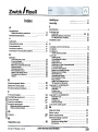
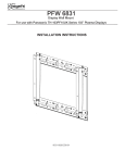
Contents
of the section
rnJ
Materials testing machine
Section contents
Contents
Safety
2
[Z]
Installation
3
manual
User manual
1
Reserved for expanded operation tC-OPSTDAL
5
~
Reserved for retro-fit parts instruction manual
~)
[;i]
Reserved for special user programs.
l===:J
..
I
J
i
0
1
Technical manual
~
I8
manual
~
~
~
Section
~
~
ril
m
7
Free.............
8
Free
9
Service and maintenance manual
110
Circuit
1 '1
diagrams
Reserved for spare parts/wear and tear parts lists ..........
Certificates/Calibration
I
,
reports
..12
1:3
Free.........................
1.4
Appendix
15
05.04/ldent / V3.0
Zwick technical documentation
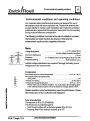
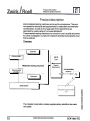
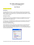
Use of the instruction manual
Materials testing machine
rnJ
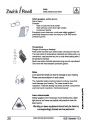
Reserved
These sections could contain the following documents corresponding to
your purchased components.
Section 5
"Expandedoperation"
Aimed at the operating personnel and describes the
possibilities of operation without a PC.
Section 6
"Retrofit parts"
is without documents in the initial delivery. You can tiile
away the description(s) of subsequently supplied parts
in this section.
Section 7
"Special user programs"
Contains an introduction to the purchsed PC software.
Section 12 "Spareparts/Wearand tear parts"
are not contained in the instruction manual as
standard.
Section 13 "Certificates ICalibration reports"
The declaration of conformity or the manufacturer's
declaration, calibration reports, safety data sheets B,nd
other certificates are to be found in this section.
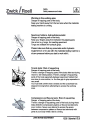
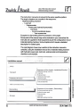
Directories
The instruction manual uses contents and hit word indexes.
.E
J
Lists of contents:
To be found on the third page of the
respective section.
Hit words:
To be found at the end of the respective
I
<3
of
j
i
i0
register.
I
05.04/ldent/V3.0
Zwick technicaldocumentation
5
~
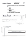
Use of the instruction manual
Materials testing machine
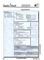
Each page of the instruction manual contains all important information on
the
- Manual
- Chapter
- Device
as well as for
- Dateof compilation
-Filename
- Versionof the description.
We'd like to make this clear to you with an example.
Device with order no.
(Electronics or type of drive system could be contained here)
Chapter
(These can be found in the respective list of contents)
Pictogram of the manual
(Navigation help)
~
I8
4
I
1
~
0
I
Description of the company
Materials testing machine
rnJ
!
I8
..
I
i
~
0
I
05.04/ldent/V3.0
Zwick technical documentation
9
!
I8
J
i
~
0
I
04.03/ Silnhalt / V2.5
Serial
number:
AB/Dossier
number:
Zwick technical documentation
168336
653782
~
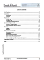
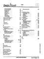
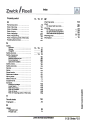
List of contents
List of contents
:3
Introduction
:5
Supplements
Transpol1
5
16
Proper use
Improper use
Remaining risks
Checks and preventive measures
7
8
9
10
Symbols and signal words
Symbols on the test systems
Signal words in the instruction manual
11
11
12
Personnel
13
13
Operator
Workplace
Safety measures and notes
Beforeswitchingon
15
16
,
At operation
At Service and maintenance
When working with electrical equipment
When working on laser light sources
When working on hydraulic and pneumatic equipment
16
16
21
22
22
23
Cleaning and disposal
24
Index
25
~
!
13
~
I
1
~
0
I
04.03/ Silnhalt / V2.5
Zwick technical documentation
3
Safety
Introduction
~
Introduction
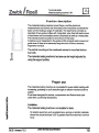
The test system is manufactured to the state of the art technology and to
recognised safety requirements. This, however, neither excludes any
danger to life and limb of the operator or third parties which could occur
when using the test system. Nor can interference nor impairment to the
impact tester be excluded.
The test system may only be used if it is in perfect technical order as long
as it is being used properly. At the same time safety and hazard risks as
well as observation of the contents of the instruction manual must be
taken into account. The test system must be shut down immediately
should any interference occur that impairs safety. The interference or its.
cause must then be rectified.
Supplements
Supplement the user manual with instructions from national regulations
on accident prevention and environmental protection.
Please observe and adhere to:
Valid, binding regulations on accident prevention
Recognised technical rules for safety and correct working
- Regulations on safety and health protection when preparing and usirlg
-
working means
Instruction manuals
The entire instruction manual must always be available at the installation
site of the test system.
~
1
<3
oe
I
i
~
0
J
10.05/ Sicherheit / V2.9
Zwick technical documentation
5
Safety
Proper use
[4J
Proper use
Our materials testing machines can be used to determine properties on
test pieces such as bars, shaped elements, components and etc. The
testing machines apply mechanical loading to the test piece in the form
of continuous, increasing, pulsating or cyclic tests through an electrical or
hydraulic drive system.
The test pieces are loaded via the test quantities force, moment or
deformation with defined values, time sequence and frequency.
The materials are undergo destructive or non-destructive tests
depending upon the testing machine and test method used.
The classical types of test are tensile, compression, flexure and torsion
test on the basis of a variety of test standards.
Please make sure that the specimen and specimen mountings used can
neither be propelled away from the testing machine nor can drop to the
floor when under load, or in the case of failure. This could lead to damge
to test equipment and to injury to persons in the vicinity of the machine.
The instruction manual is constructed in modular form. Thus observe
section 2 "Technical manual". This section describes the proper use of
each component.
Inspection and maintenance, transport, installation and operating
instructions belong to the proper use of the test system.
~
!
8
~
j
i
(
0
i
10.05/ Sicherheit / V2;9
Zwick technical documentation
Safety
Remaining risks
I4l
Remaining risks
Remaining risks may be present in, for example, the following cases (F;or
examples also see DIN 51233):
Using hardened or ceramic jaw inserts without protection against
-
shattered parts
Danger of trapping fingers, etc. when opening and closing
-
specimen holders which are electrically, hydraulically or
pneumatically operated.
Specimen or parts of specimen that are, or can be, propelled away
from the test system or fall to the ground with high energy
absorption and resilience owing to the type of loading and the
propertires of the specimen, i.e.
- Springs
- Ropes
- Belting
Basically we stipulate that the user is well versed in the use of the test
system.
We offer a range of safety devices that are aimed at providing protection
for the user and for the vicinity of the test equipment. We stipulate the u:;e
of a safety device with electrical interlocking for the test area dependin~~
upon the components and applications to be employed by and with the
test system. In this case the maximum drive speed is limited to 600 mrTll
min and the test load is limited to the set preselections in verification
operation. These limits apply when the safety door is open. Section 4
(Operator manual) explains the verification and test operation in more
detail.
In addition inching operation has been realised at the testControl
electronics.
The test itself is run only if the safety door is closed and interlocked.
!
.e
~
The speed limit of 600 mm/min for opening and closing specimen
holders is a safety precaution for pneumatic and hydraulic specimen
holders.
j
i
~
0
I
10.05/ Sicherheit / V2.9
Zwick technical documentation
9
[4l
Safety
Symbols and hit words
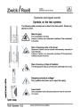
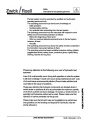
gymbols on the test systems
The following safety remarks can be fixed to the test system. Please pay
attention to them.
-/tt\
~
Risk of injury!
The crosshead is moving.
Caution: Caution, no automatic shutdown if the crosshead
is touched.
Risk of trapping parts of the body!
Specimen holders can be closed mechanically, manually or
automatically.
Caution: Caution, no automatic shutdown if the specimen
holder(s) is(are) touched.
1:1
[
/
Risk of burning or Risk of frostbite!
The temperature device can become extremely hot or cold.
Iii
/
/
'=
~
~
i~
Q
8
II
I
i
~
0
Dangerous electrical voltage!
Only qualified electricians are to open the casing.
Laser beam!
Only competent
on Lasers.
and authorised
i
u
System display
10.05/ Sicherheit / V2.9
Zwick technical documentation
persons may do any wor1(
Safety
Instructions for the operating personnel
[4]
Personnel
A differentiation is made in this instruction manual between user and
operating personnel.
User:
Responsible personnel with authority for giving
instructions
Operating personnel: Persons who work at or with the test system
Operator
The machine safety can only be implemented in every day use if all
necessary measures are taken.
Determine the operating personnel's responsibilities for
Operating
Setup
Maintenance and repairs
Tuition on the above is offered by Zwick
The test system's user must make sure that the following is observed
(Due diligence).
The test system may only be used according to its proper use.
Only safe tests may be run with the test system
The test system may only be used if it is in perfect working order
Anything that could impede safety has neither been added nor
converted
Safety devices have not been manipulated
Check all safety devices (Safety devices, limit switches, proximity'
switches and EMERGENCY OFF button) for evident malfunctions,.
Should the test system malfunction in any way, further operation is
permitted only following consultation with the responsible safety
officer (If necessary please ask Zwick)
All safety remarks and warning signs attached to the test system
must not be removed and must be legible.
!
i
g
08
I
i
~
0
J
10.05/ Sicherheit / V2.9
Zwick technical documentation
....
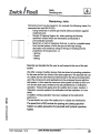
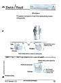
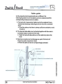
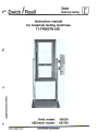
Workplace
The operator's workplace is in front of the materials testing machine
during operation.
.
Table
Materials testing machine
installed by a wall
Wa
Stool
Workplace
Workplace
Recommended minimum distance to walking lanes
~~1~"j'~~~
"".-""
..~~.~
~~ ~!~~
~~~~~~~~
-4
~
Materials testing machine setup free
in a room
~
!
8
01
Lateral and rear protection
j
i
~
0
Workplace
Recommended
minimum distance
to walking lanes
J
Exemplary drawing
~
10.05/ Sicherheit / V2.9
Zwick technicaldocumentation
15
Safety
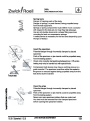
Safety measures and notes
Safety device
Please use a safety device for any potentially dangerous test
requirements (Safety door with electrical interlock).
Examples of potentially dangerous test conditions:
Using hardened or ceramic jaw inserts without
-
protection against shattered parts
Specimen or parts of specimen that are, or can be,
propelled away from the test system or fall to the grour1d
with high energy absorption and resilience owing to the
type of loading and the properties of the specimen suc:h
as
- Springs
Ropes
Belting
'.
~
Rotating lead screws
Be carefulwhen lead screws,suchas thosefor crossheadsor
extensometersare rotating.
Longhair,jewelryor looseclothing(E.g.sleeves)couldget
caughtup in rotatingleadscrews.
Pleasetake the followingprecautions
- Wear closelyfittingclothing
Do not wearjewelry
Use a haimetif necessary
~
Working area
Risk of squashing and/or potential danger through falling
.&
~
..
!
objects.
Never place objects in the materials testing machine's test
area nor on the test tools.
0)
u
..
j
i
s...
0
I
u
10.05/ Sicherheit / V2.9
Zwick technical documentation
17
Safety
Safety measures and notes
(4l
Spring tests
Danger of trapping parts of the body.
Danger of springs, or parts thereof, being propelled away
from the test equipment.
Springs or spring components must neither move crosswisE~
with respect to the test axis nor may they slip sideways.
Use an anti-buckle device and a shape fitting specimen
mounting for tests on compression springs.
A safety device is necessary for the test area depending upon
the type oftest(s)!.
Insert the specimen
Potential danger through incorrectly clamped or placed
specimen:
Parts of the specimen or jaw inserts could be propelled away
from the testing system.
Check only correctly clamped/insertedspecimen. Off-centre
testing may only be carried out with special tools.
Compression test devices may have a centring groove or a
guide mandrel. The specimen must then either be seated in
the groove or secured against being propelled away from the
test device by the mandrel.
Flexure test
Open the grips
Potential danger through incorrectly clamped or placed
specimen:
Parts of the specimen or jaw inserts could be propelled away
from the testing system.
Never ever open specimen holders that are under load.
Any load must be removed from the clamped specimen
before opening the specimen holders.
iJ
i
,1
j
I
I
0
j
10.05/ Sicherheit / V2.9
Zwick technical documentation
19
Safety
Safetymeasures and notes
[4l
At Service and maintenance
Please note the following points to help avoiding serious injuries or
machine damage when carrying out maintenance work on the test
system. These topics are listed for each component in section 10 "Service and maintenance manual":
Adhere to prescribed Inspection and maintenance intervals
Please pay attention to the maintenance and service manuals.
Only use the indicated operating fuels and lubricants, etc.
Use original Zwick spare parts only
Before carrying out any maintenance or repair work:
Switch the mains supply off via the main switch. Secure the main
-
switch against inadvertant switching on with a padlock.
Unplug the mains plug or disconnect the mains connection.
Wait until all parts of the materials testing machine that may
perhaps be touched (E.g. motor, temperature chamber, etc.) have
cooled down to ambient temperature!
Check the following after maintenance or repair work:
Have all threaded connections been screwed tight again?
Have container lids/covers, sieves or filters that have been removed
been replaced again?
Have all materials, tools, equipment, etc. that were required for
maintenance and repair work been removed from the materials
testing machine's working area?
Have any liquids that may have leaked been removed?
Are all safety devices such as limit switches, proximity switches and
the materials testing machine's EMERGENCY OFF button in
perfect working order?
:~
All of the above work must be first correctly done free of error before the
materials testing machine is to be used by the operating personnel.
1
c1
-
Only use lifting tackle (Such as a fork lift truck, crane, etc.) that is suitab~e
and in first class condition when replacing or exchanging heavy machine
j
parts!
J
I
0
.J
10.05/ Sicherheit / V2.9
Zwick technicaldocumentation
2
Safety
Safetymeasuresand notes
[4l
When working on hydraulic and pneumatic equipment
Hydraulic
Maintenance and repair work on hydraulic and pneumatic equipment
must only be performed by competent personnel trained and with
experience in hydraulics/pneumatics!
When working with hydraulic oil please observe the corresponding
remarks on the safety data sheet (Section 13 "Certificates/Calibration
reports").
Set the materials testing machine to zero pressure when carrying
out maintenance and repair work on pneumatic and hydraulic
equipment!
These topics are listed for each component in section 10 "ServiCE~
and maintenance manual"
Please check all leads, hoses and threaded connections for
leakage and for visible damage!?
Replace any damaged hoses/pipes immediately!
Spraying oil could lead to injuries and fires!
Risk of slippage
~
m
As a precautionary measure, please replace all hydraulic hoses
every 6 years (Recommendations to DIN 20066 Fluidics - Hoses)
even if damage to them is not obvious!
Hydraulic oil may escape when cleaning the equipment.
Please make sure that emergency precautions (Oil sump, oil
binders, etc.) have been taken to make sure that oil cannot intrude
into the ground and/or the sewer system.
Please adhere to the safety data sheets for the hydraulic oil used
and to the necessary rules and regulations.
Hydraulic oil and contaminated agents (Oil binders) must always be
disposed of in an environmentally safe way. The safety data sheets
are to be found in section 13 "Certificates/Calibration reports"
When replacing hydraulic and compressed air hoses, mount theml
in the same manner/direction.
!
8
~
I
i
I
0
J
10.05/ Sicherheit / V2.9
Zwick technical documentation
23
Index
13
.6
12
Instructing the operating personnel
Instructing the transport personnel
Index
Instructionmanual.........................
A
Authorised personnel
Avoiding waste .........
13
24
B
16
Before switching on
10
24
20
23
18
Checks and preventive measures
Cleaning recommendations .........
Cold ............................................
Compressed air hoses ................
Compression tests ......................
D
Definition
CAUTION
DANGER
WARNING
.c
,
~::.:::...
............................................
Disposal......................................................
in an environmentally safe manner
Document..................................................
Disposal
12
12
12
24
24
.2
............
............
............
13, 16,
. . .. ... . ..
Lasers .........
Lifting tackle
Limit switch.
22
20
21
21
,
EMERGENCY OFF button ...........
13, 16, 21
22
Heat.....................
j
Hydraulic systems
Hoses ..................
J Hydraulics ............
g
0
Insert the specimen .................
Inspection intervals ..................
Instructing operating personnel
01.02I Silndex I V2.0
Maintenance
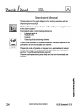
,
,...
Maintence work
Environmental protection
Minimum distance ...............
24
15
N
.5
20
0
Oil sumps ......
Open the grips
Operate ..........
Operation .......
14
19
16
13
18
p
H
I
~
..
22
23
23
21
Mains connection ................
Mains plug ..........................
20
F
Flexure tests
Maintenance work
Electrical equipment ......
Hydraulicequipment
......
Pneumatic equipment .".
Switch off
",.
safety ....................
Noiselevel..............
Ear protectors ..............................
Extensometer TC-EXOWMST. HO1
Safe operation .........................
Maintenance intervals ..........
13
21
21
21
21
Machine
National regulations
E
j
Laser.
M
C
!
L
Padlock.............................
20
23
14
23
Perfect working order ........
Personnel..........................
Personnels responsibilities
Pneumatics .......................
Preventive measures .........
Print date ..........................
19
21
13
Proper use ........................
21
13
13
13
23
10
.2
7
Protection
Clothing.......................
Zwick technical documentation
14
25
~
~
!0
u
..
j
~
I
0
i
u
Serial number:
AB/Dossier number:
05.04/THlnhalt/V3.0
Zwick technical documentation
168336
653782
~
Zwick IRoe11
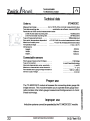
List of contents
General
,
2
Technical details
7
Materials testing machine T1-FROO5TN.A50
Measurement
module TC-MODCSCC
"
9
'
"""'.'
'
TC-OP500HZ
:
Load cell, function description
~...:
Load cell TC-LCOO20N.PO1
Load cell TC-LCO200N.PO1
VideoextensometerTC-EXVIDEO.OO2
Environmental conditions and operating conditions
c
:8
Index
'..""'...'.."'
21
23
25
29
31
33
35
39
~
!
8
~
j
i
~
0
J
05.04/THlnhalt/V3.0
Zwick technical documentation
3
Test standards
Materials testing machine
Applied standards
The test standards relevant for materials testing machines are listed in
the
Declaration of conformity
or the
Manufacturer's declaration
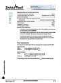
Remarks on product and manufacturer's liability
The accuracy limits stated in our specification(s) (order confirmation) are
not infinitely valid. Regular checks must be made depending upon the
measurement accuracy.
You can do this yourself if you have the necessary measurement means.
If not, it can be done by accredited centres such as materials testing
authorities or by Zwick. The Zwick DKD calibration laboratory is
accredited under registration no. DKD-K-13201.
Remarks:
We recommend annual calibration with respect to EN ISO 9001
E
5
I
8
~
I
!
~
iu
05.04/THlnhalt/V3.0
Zwick technical documentation
5
~
Zwick I Roell
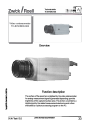
Technical details
This section contains the description of the materials testing machine
with all accessories.
All technical details are contained here. The correct use of the materials
testing machine and all accessories used with it are defined here. You
can even read about impermissible application and use here.
Do you require the ratings or operating means still to be acquired? You'll
find all values necessary for the materials testing machine here.
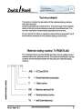
Materials testing machine T1-FROO5TN.A50
The materials testing machine (MTM) described here is a table-top test
machine with a max. test load of 5 kN. The machine identification (name)
contains all characteristical details for this particular materials testing
machine.
.A50
= AC Drive 500 W
N
= Normal load frame construction
T
= Table machine
j
005
= Maximum test load 5 kN
i
i0
FR
= Materials testing machine
T1
= testControlelectronics
E
5
i
8
~
.
J
04.03 I Tech IV2.7
Zwick technical documentation
7
~
~
i
8
..
I
!
~
0
I
I
..~
....
I
MTM T1-FROO5TN.A50
Technicaldetails
.......
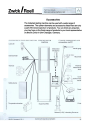
Overview
Head plate
crosshead
-
Load frame
Moving
Workarea
Fixedcrosshead
Motor
Zwick technical documentation
Contact area to the floor <
~upportprofil~
Secure
Main switch
Zwick Roell
ccjj]ijj]jj
04.03/Tech /V2.7
/
Position
cross
head
pointer
pointer,
Main switch
EMERGENCY OFF
button
9
~
Zwick I Roell
Measurement
and conb'ol electronics
Test data recording rate in the system
Test data transmission rate to the PC
Numberof moduleslots
500 Hz
Adjustable from 10 to 100 Hz
2
,
Zero-drift correction of the entire measurement chain
without sensor
Measurement signal, runtime correction
Output interface
Required PCconnection
Automatic at measurement begin
Yes
RS232
.. ...
"'."'.'..."'..."'."'
'
COM 1
IP 32
Typeof protection,casing
Remarks on the electronics
- A maximum of two test data recording p.c.bs can be installed in the electronics,
the module slots are not expandable!
The ventilation slits in the electronics unit must never be covered, not even those
on the unit's underside. They require a free spacing of at least 100 mm.
The testControl electronics must have a constant temperature for exact
measurements. Thus switch the materials testing machine on an hour before
the beginning of test, especially for long term tests.
Force measurement
The measurement electronics for the force measurement corresponds to ISO 7500/1
Load cell, type I
Grade1
In the range of 0.4 to 100 % of Fnom'
Grade 0.5
In the range of 2 to 100 % of Fnom'
Load cell, type II
Grade1
At Fnom>=500N in the rangeof 0,2to 100%,
Grade 0.5
At Fnom<= 200 N in the range of 0.4 to 100 %,
In the range of 1 to 100 %
The percentage values refer to the nominal force
(F nom) of the connected load cell.
!
!.;
u
oS
~
~
~
0
J
18
04.03/Tech /V2.7
Zwick technical documentation
11
~
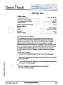
Operating data
Rated values
Electrical connections ........................................
Full load current consumption '.'.'
'...'
"".'"
Power consumption (Full load) ...........................
Mains frequency .................................................
Mains fusing for the power supply ......................
Mains output
Socket
..............
Voltage ........................
Mains drift ....................
Maximum loading .........
,
,
,
230 V (Ph, N, PE)
9A
1.9 kVA
50160Hz
<= 16 A
CEE 7 (Schuko)
230V(1PH, N, PE)
:f: 15 %
,."""",.""".."",.""",.,...""",
1 kW
Leakage current monitoring
The materials testing machine is works equipped with interference
suppression filters (EC laws). Interference suppression filters have
leakage current to earth. This current is monitored by your installed
leakage current monitoring devices (FI circuit breaker). A single
materials testing machine doesn't trip a leakage current monitoring with
30 mA. Should your power supply be subjected to heavy interference, or
if several materials testing machines are operated on one common
FI circuit breaker, the sum of leakage currents could trip the FI circuit
breaker.
You can help yourself by
- Running one materials testing machine on one FI circuit breaker
or
- Use an earth leakage circuit breaker with a higher response threshold
if this is permitted
or
If your national laws and regulations, or works regulations allow it then
don't use an FI circuit breaker.
~
or
- Use a DC isolated series transformer such as our BTCACTRAFO.230for example.
I
8
~
I
i
~
0
J
04.03/230V_Tech/V2.7
Zwick technical documentation
13
Technical details
Materials testing machine 5 kN
0
Function description
The materials testing machine's load frame, and the electronic
measurement and control unit of the testControl machines constitute the
basic unit for testing a range of materials. The load frame consists as
standard of two guide profiles with integrated, play-free ball lead screws
a fixed lower and a moveable central crosshead as well as a head plate.
The mechanical drive system is to be found in the base.
A bellows cover integrated in the guide profile protects lead screws and
guide even if there is an extremely large amount of fibrous remains,
fragments and dust.
The central mounting on the crossheads serves to mount test tools or
load cells.
~
~t
81
8'
8I
t.~
The materials testing machine's test area can be height adjusted by
using the support profiles.
Proper use
The materials testing machine is concipated for quasi-static loading with
increasing, pulsating or cyclic tests through an electro-mechanical drive
system.
It has been designed for tensile, compression and flexure tests (see
under EEC conformity declaration).
E
5
I
8
..
Limitation
The materials
I
!
~
testing machine
is not suitable for tests
On elastic specimen such as elastomers, springs or similar materials
where the actual test load is 50 % greater than the machine's nominal
force
I
06.02/ Verwend / V2. 1
Zwick technical documentation
15
Technical details
Materials testing machine 5 kN
~
Should one or more of these sources of danger exist owing to the the
testing machine's equipment or setup, a suitable safety device (e.g.
safety door, shield, etc.) must be installed.
The safety device is used to protect the operator and the vicinity.
Therefore the function of the safety device must never be deactivated
Improper use
Materials testing machines must not be put to use for any kind of
applications whatsoever that constitute potential sources of danger for
persons and for the environment.
Emissions
Heating up
The motor temperature can reach 80° C when performing cyclic tests
(Continuous testing).
Free from vibrations
Vibrations and jolts at specimen break are dependent upon the material
tested, and on the test arrangement.
!
I
8
j
Noise level
The materials testing machine's noise level is listed in the technical data
A loud noise can be generated at specimen failure (specimen break).
We recommend the use of ear-protectors for such tests.
1
N
~
0
J
06.02/Verwend /V2.1
Zwick technical documentation
17
~
Zwick I Roell
Accessories
The materials testing machine can be used with a wide range of
accessories. The system elements and accessories listed here are only
a part of the Zwick spectrum of products. You can direct any enquiries
you may have on the Zwick range of products to your local representative
or direct to Zwick in Ulm-Einsingen, Germany.
~
Overview
E
5
I
8
of
I
I
~
0
The TC-MODCSCC module is the link between a test data recorder with
a strain gauge measurement bridge, e.g. a strain gauge load cell, and
the testControl electronics.
I
01.02/Tech /V2.0
Zwick technicaldocumentation
21
~
~
J
Option TC-OP500HZ
This option enables you to switch the transmission rate from 100 Hz to
500 Hz. Switching can be made in a test program at the PC only.
Technical data
Order no. ...................
Transmission rate.......
Softwareswitching
BTC-0P500HZ
100 Hz or 500 Hz
j
!8
..
I
i
~
I
01.02/Tech /V2.0
Zwick technical documentation
23
Functiondescription, testControl
Load cell
~
Load cell, function description
Load cells convert the physical quantity force to an electrical, measurable
current. It consists of a mechanical deformation body with bonded strain
gauges (StrG)
Strain gauges are strain dependent electrical resistances that are
connected together to a measurement bridge.
The value of the measurement voltage at the measuring bridge output is
analogue to the force (F) to be measured; this force acts on the
deformation body and on the entire sensor system.
The sign (polarity) for the measuring voltage changes depending upon
the tensile or compression loading of the load cell.
Measuring voltage (-J
;-.;.
SupplyYoltage (+)
Measuring voltage (+)
~
Supply voltage (.
Screen
Casing (mass)
A first class, screened data cable with a 25-pin sensor plug establishes
the connection to the measurement technology's measurement amplifier.
The sensor plug's p.c.b. has a small data memoryIC to which the load
cell's characteristic and calibration data (important for the system
setting) is saved.
§
I..
U
01
I
~
~
0
Plug casing
--Lr
Connecting cable
.~~
f
C)
.~
J!;
-as
as~a.
j
04.02/ Ffunk / V2.1
Zwick technical documentation
25
~
Zwick I Roell
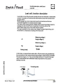
Definition of the characteristics
The VDINDE guidelines 2638 (April 89) define the following
characteristics for load cells:
E
5
Nominal force
The nominal force for which the load cell has been
Fnom
designed.
Maximum operational force
FGin N
Greatest force in the direction of the load cell's
measurement axis up to which a defined and repeatable
relationship between the force and the output signal exists,
however an eventually existing protection against
overloading won't be tripped at this point.
Force at break
FBin N
Force in the direction of the load cell's measurement axis
above which mechanical destruction must be reckoned
with.
I
8
..
j
i
~
0
j
8,
04.02 I Ffunk I V2. 1
Zwick technical documentation
27
~
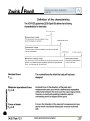
Overview
8,
c
.
,~
~
I
8
4
I
!
~
Load cells convert the physical quantity force to an electrical, measurable
current.
I
01.02/Tech /V2.0
Zwick technical documentation
29
~
~~
= ==~-~~--,
~
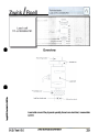
Overview
!
Ig
.
j
!
Load cells convertthe physical quantity force to an electrical, measurable
current.
~
0
Iu
01.02/Tech /V2.0
Zwick technicaldocumentation
31
Technical details
Tc-EXVIDEO.OO2
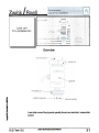
Overview
E
5
Function description
I
8
~
The surface of the specimen is digitised by the video extensometer.
An analog measurement signal is generated depending upon the
brightness of the captured surface area. This is then converted to a
digital signal by the related measurement electronics and is then
evaluated by a picture processing program on the PC.
i
!
i
I
01.04/Tech /V2.0
Zwick technical documentation
33
Environmental and operating conditions
GJ
Environmental conditions and operating condition~.
Our materials testing machines and testers are designed for use in
atmospheres that are not an explosion risk. Please note that the user
accepts liability to choose a safe installation site. Explosion protection
guidelines also require that the explosion hazard and thus the resulting
zoning must be taken into consideration.
The following conditions must exist at the site of installation to enable
reproducible and exact results to be obtained. Otherwise the
measurement results could be negatively influenced.
Mains
Voltage fluctuations
Short term interference
Frequency ...................
Protective earthing ......
.t;
~.t; 10 % related to the
nominal voltage connection as offered
~ 20 ms
1 % related to the nominal frequency as per our offer
Earth resistance ~ 5,Q
Suitable voltage stabilisators are required if strongly fluctuating mains
voltages are to be reckoned with.
Temperature
Permissible range for Ambient temperature
+10 °C to + 35 °C
Permissible ambient temperature drift
during a test
:t 1K
Humidity, non-dewing '."".".".."..."'
'."'
"...'
20 % to 90 %
Transport and storage temperature
- 25 °C to + 55 °C
Please make sure of sufficient ventilation. You must place a de-humidifying agent
to the materials testing machine if it's to be stored for a lengthy period of time.
~
System operation emits heat depending upon the performance. Please
take measures to ensure sufficient heat dissipation.
I
8
~
I
Type of protection
Correspondsto IP32(To EN 60529).
The electronicsis protectedagainst:
. Solidforeign bodieswith a diametergreaterthan 2,5 mm
. Drippingwater if the casingis inclinedup to 15°.
~
~
0
J
05.04/ TUmgeb / V3. 0
Zwick technical documentation
.
Zwick IRoe11
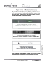
Connection of computer systems/Peripherals
Devices connected to the materials testing machine must be within the
radio interference limits.
Interference free operation is only possible if these devices are plugged
into the materials testing machine's mains output sockets, or connected
to the same phase plug as that for the materials testing machine.
Whereby all cables should be as short as possible.
Compressed air
The materials testing machine does not require any compressed air.
However, some of the optional test tools used in conjunction with the
machines require compressed air.
Operating pressure ..................................................
with recommend oil to .........................................
6 to 10 bar
ISO3448
Viscosityt...........................................................
32 mm2/s
filtered, dehumidified and oiled
'8
Water, Gases
The materials testing machines require neither water nor gas supplies.
An exception is hydraulically operated testing machines and some
optional auxiliary equipment/devices which need water and gas for
cooling.
Please ensure sufficient ventilation for emission of gases.
!
!.;
u
~
!
~
l
0
I
,.
05.04/TUmgeb/V3.0
Zwick technical documentation
37
~
Zwick I Roell
Index
Heating up
17
:;.:~.J:
,..'::...:.::
Humidity ..
35
A
Accessories
Materials testing machine ..............
19
35
Ambient temperature ...........................
C
28
37
37
37
Compressed air
Computer systems
Connection of computer systems
D
Definition
Characteristic value
Force at break
28
27
28
27
27
Limitlateralforce
Maximum operational force
Nominalforce
,
Operationalforce
"",..,."",
Permissible
torque
Staticlimitlateralforce
"
Temperature
influence
"
Torque
",.,.",...,
,
,..",.",..,
,..,
,..,
",.,.,..,
,
"
27
28
28
28
28
E
Electromagnetic fields ............
Electronic rating plate ............
Environmental conditions ........
~
12
35
F
!
8
~
I
!
~
0
i
(.)
FI Circuit breaker """""'."".'."".'.""
Fire fighting equipment .....................
Force at break ..................................
Free from vibrations
,
Function description
Materials testing machine ...........
Videoextensometer....................
13
18
27
17
.. 15
..33
G
Gases....
37
H
Hazardous use
01.02/THlndex/V2.0
6
30, 32
17
"""""""""""""""'"
22
38
5
Calibration
Characteristic
value
!
Identification
Improper use
Load cell
Materials testing machine
TC-MODCSCCmodule
Installation plan
. 16
L
Leakage current monitoring
""""",.""
Limitation
Limitations
Video extenso meter
Load cell
Cable guide
Characteristic value
Data cable
Data memory
Definition of the characteristics
Force at .break
Function description
Maximum loading range
Measurementrange
""
34
25
26
28
25
25
27
27
25
27
27
27
""""""""""""",."""",
Nominal force
Operational range
,."",..""""",
Permissible torque
Plug casing
Static limit lateral force
Temperatureinfluence
Load cell TC-LCOO20N.PO1
Improper use '
".."'.'.""""."".."."""..'
Overview
Proper use
Technical data
Load cell TC-lCO200N.PO1
Improper use
Overview
Proper use
Technical data
Load cell's cable guide
13
15
,.""
27
28
25
28
28
30
29
30
30
32
31
32
32
26
M
Magnetic fields ....................
Mains output .......................
Mains requirements.............
Materials testing machine
Accessories ...................
Electronic rating plate ....
Emissions ......................
Zwick technical documentation
36
13
35
19
12
17
39
Index
Force measurement .....
Function description .....
Hazardous
use '
'.
Improperuse .................
Loadframe....................
Operating data
0/er.fIeIN
Proper use "
,
,
'
'.."
Technical data ...............
Technical details ...........
Maximum operational force
Measurement amplifier .......
Measurementbridge...........
11
15
16
17
10
13
.9
15
10
.7
27
25
25
N
Noise level.....
Nominal force
~~
27
0
Operating conditions .............
Operating data
Materials testing machine
35
13
0Jerview
Load cell ..........................
Materials testing machine
TC-MODCSCCmodule .....
Videoextensometer.........
29, 31
9
21
33
Video extensometer
34
T
TC-MODCSCC module
sensors.......
Improper use ....................
0tIerview ...........................
Proper use .......................
Technical data ..................
22
22
21
22
22
TCOPSOOHZ
Technical data ..................
23
Connectable
Technical data
Load cell ..........................
Materials testing machine
TC-MODCSCC module. . .. .
30, 32
...... 10
""" 22
...... 23
...... 34
.......,. 7
...... 28
...... 35
...... 35
TC-OP500HZ....................
Video extensometer .........
Technical details ...................
Temperatureinfluence ...........
Temperaturerequirements .....
Type of protection ..................
V
Video extensometer TC-EXVIDEO.OO2
Function description .......................
Limitations .....................................
0Ierview "'.""""""""""""'.".'.."...
Proper use .....................................
p
System description ........................
Technical data ................................
Permissible
torque
................
Power consumption
...............
Proper use
Limitations
.......................
Load cell ..........................
Materials testing machine
TC-MODCSCC
module. . . ..
Videoextensometer .........
28
13
...... 15
30, 32
33
34
33
34
34
34
W
Water
37
...... 15
...... 22
...... 34
R
Rated values
...............
Requirements
for fixing
I
13
0
38
~
S
Serial number plate .....
Static limit lateral force
Storage temperature .....
Strain gauges ...............
Structural requirements
r
.6
28
35
25
38
~
AD
~
i
i
System description
Zwick technical documentation
01.02/THlndex/V2.0
Environmental and operating conditions
~
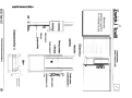
Installation plan
The space requirements are listed in the Technical manualunder
paragraph Technical data.
Storing accessories
Depending upon the accessories to be stored, you should have a
lockable storage place (Cabinet or similar). This furniture hasn't been
taken into consideration for the installation plan.
Why a cabinet that can be locked-up? Extensometers, load cells and
physical measurement units such as Vernier gauges, micrometers,
scales are measuring devices and must be well protected against
damage.
Structural requirements
The specific loading of the floor for the materials testing machine is listed
in the technical data. Please note that the height of the room must be
approx. 20 cm higher than the test machine's maximum height (see the
respective technical data).
Requirements for fixing
{
0
The materials testing machine is normally free standing, however, some
hydraulic testing machines are fixed to the floor.
Align the machine and pay attention that it stands safely on its own on a
level floor.
I
or
I
'"
~
i
i
38
Zwick technical documentation
05.04/ TUmgeb / V3.0
Environmental and operating conditions
~
External influences
Materials testing machines and testers are highly sensitive measurement
systems. Thus the following must be avoided at the installation site:
. Jolts and vibrations
. Oscillations
. Vibrations
. Schock
. Conducting air
. Corrosive contamination
Recommendation
Installing shock absorbers, air filters or signal filters.
We would be only too pleased to be of assistance to you should you be
confronted with these problems.
Electrical, magnetic and electromagnetic fields
Our materials testing machines and testers are laid out to the now valid
EMC guidelines.
The following measures have already been taken against the named
interferences in the construction of materials testing machines with
electronics consoles:
. Enclosed metallic casing.
. Screened leads.
. Connection of all devices and screens to the protective earthing.
. Star shaped reference conductor system.
You must take the following measures if the above ones are insufficient:
. Place power cables spacially separate to measurement leads.
. Use twisted wire pairs for self-made measurement leads, each wire
.
pair should be separately screened (Screen mesh).
Screen the materials testing machine from any nearby
- Substations
- Busbars
- HF generators (Such as induction oven, welding gear, etc.)
I0
~
i
I.
~
i
i
Zwick technical documentation
05.04/ TUmgeb / V3.0
Technical details
TC-EXVIDEO.OO2
~
Technical data
Order no.
BTC-EXVIDEO.OO2
This order no. for the videoextensometer includes a video camera, a picture
processing software and a PC hardware dongle.
The technical datafor the video camera can be taken from the separate video
camera instruction manual.
System description
The measurement system is a digital video camera with a picture
processing system. The resolution and measurement range can be
adapted to the properties of the materials to be tested by a suitable
selection of camera lenses.
The picture of the specimen digitised by the video camera is processed
in a PC supported video processor in real time.
Proper use
The video extensometer makes non-contact and high resolution tensile
and compressive deformation measurements on all types of plastics,
metals, rubber, laminates, wafers and foils.
I0
Limitations
There is a risk of fogging in a temperature chamber when this
extensometer is used in conjunction with Co2 or LN2 cooled temperature
chamber. It may eventually be necessary to wait several minutes before
proceeding with the test.
The temperature range of the temperature chamber is limited to -40 to
+120 °C when using measurement marks on the specimen being tested.
Zwick technical documentation
01.04/Tech/V2.0
~
k
i~
~
I
i
Technical data
Orderno.
BTC-LC0200N.PO1
Nominal forceFnom
.
Maximum force to be used FG
L. .
&
Imrt ,orce
FL
Force at break Fe
,
"'
200 N
"'."..'..'..".'-'f-"'~""~"
:............................................................
;;
>:,
~.............................
~
';,.....................--.
Static permissible limit and transverse force FQ
~
120 % of F nom
150 % of F nom
>300 % of F nom
<= 10 % ofF nom
Nominalmeasurementpath........................................................
0,1 mm
Maximum temperature influence on the zero-signal TKo ................... i: 0,05 % FN/10 K
Maximum temperature influence on the characteristic value TKc
i: 0,05 % FJ10K
Measurement range, initial value:
grade 1
0,4% of nominal value
grade 0,5
2,0% of nominal value
O,8N
.. 4 N
-20
Temperature range
Type of protection. .
Model....................
+60 DC
IP42
. KAP-Z
Dimensions:
Height
......................
..86
Width .......................
Depth.......................
Mountingstuds ........
..42
..14
08
mm
mm
mm
mm
0,3 kg
Weight
Proper use
This load cell is designed for measuring static and dynamic tensile and
compression forces. It must be operated in the direction of the test axis
and to its nominal force whilst adhering to the conditions as contained
under the technical data.
I0
.
f
.I~
Improper use
8
Load cells are precision measurement devices and, as such, should be
treated with the utmost care during transport and at assembly. They could
become irreparably damaged if subjected to shocks and/or knocks.
32
Zwick technical documentation
01.02/Tech /V2.0
i
i
~
Technical details
LoadcellTC-LCOO20N.PO1
Technical data
Order no.
Nominal
Maximum
BTC-LC0020N.PO1
,.,.~~
forceFnom
force
to
be
used
~
Limit force FL '.."""""""""""""""".""...""".'
'A
u
Force at break FB
Static permissible limit
Nominal measurement
Maximum temperature
Maximum temperature
20 N
~.~
~..
110 % of Fnom
¥............................
150 % of Foom
;.~................................>500 % ofFnom
FG
and transverse force F Q..................................... <= 10 % of F
nom
path
,
0,4 mm
influence on the zero-signal TKo ................... .:t 0,1 % FJ10K
influence on the characteristic value TKc
.:t 0,1 % FJ10K
Measurement range, initial value:
grade 1
0,4% of nominal value
grade 0,5
O,08N
. O,4N
2,0% of nominal value
Temperaturerange
Type of protection..
Model....................
-20
+60 °C
IP42
. KAP-Z
Dimensions:
Height ..............
Width ...............
Depth ...............
Mounting studs
..81
mm
..60mm
..13mm
08mm
Weight
0,3 kg
Proper use
This load cell is designed for measuring static and dynamic tensile and
compression forces. It must be operated in the direction of the test axis
and to its nominal force whilst adhering to the conditions as contained
under the technical data.
I0
~
r
Improper use
I
ao
~
Load cells are precision measurement devices and, as such, should be
treated with the utmost care during transport and at assembly. They could
become irreparably damaged if subjected to shocks and/or knocks.
Zwick technical documentation
01.02/Tech /V2.0
i
i
Function description, testControl
Loadcell
~
Static limit lateral force
Fain N
Greatest force that may be applied at the load cell's force
introduction point vertical to the measurement axis without
any significant changes to the load cell's measurement
properties being detectable when using the load cell again
up to its nominal force.
This is also valid at simultaneous loading of the load cell to
nominal force.
Permissible torque torque
MGin Nm
Permissible torque about the load cell's measurement axis
without any significant changes to the load cell's
measurement properties being detectable when using the
load cell again up to its nominal force.
This is also valid at simultaneous loadingof the load cell to
nominal force.
Characteristic value
C in mVN
The output signal at nominal force is diminished by the preload signal.
Temperature influence to the
characteristic value per 10 K
TKc
Relative change to the characteristic value of the load cell
owing to a change in the temperature by 10 k within a
defined temperature range after setting the stationary
states.
I0
H
Temperature influence to the
zero-signal per 10 K
TKo
Changes to the load cell's zero-signal related to the
characteristic value due to a temperature drift by 10 K
within a defined temperature range after setting the
stationary states.
r
I
..
~
i
c
~
Zwick technical documentation
04.02 I Ffunk I V2. 1
~
iii:i!(,
~1
iiir'
"~
""' ","'C
123
cc:
i
Cable guide
As the respective test requirements are so different, the
followingrequested recommendations are to be observed and the
corresponding measures are to be taken:
1) The load cell's measurement cable must not be subjected to any
mechanical stressingor stretching at all over the entire crosshead
travel.
=> Feed the cable so that there is always sufficient available to avoid
the above.
2) The load cell data cable must not be fed together with the motor's
connection leads nor direct on the motor.
=> Feed the load cell data cable out of the cable duct above the
motor.
3) Specimen remains must not damage any part of the load cell
measuring cable at specimen break.
=>Place the cable so that it is correspondingly protected.
I0
~
i
I
..
~
i
c
~
26
Zwick technical documentation
04.02 I Ffunk I V2. 1
Zwick I Roell
Technicaldetails
TC-OPSOOHZ
I0
.
r
I
to
~
i
j
Zwick technical documentation
01.02/Tech /V2.0
Technical details
TC-MODCSCC module
~
Technical data
Order no.
BTC-MODCSCC
Measurement range
0,2 to 165 % of the nominal measurement value
Test data recording rate
switchable via software, maximal 500 Hz
Resolution at 100% nominal measurement value:
at 500 Hz test data recording rate
162000 points
at 50 Hz test data recording rate
297000 points
Type of measurement input ...........
Zero-point, temperature dependent
Maximum linearity error .................
Temperaturerange ........................
Differential input
< 5* 1Q-4%/K of nominal measurement value
+1-0,01 % of measurement end value
+10 to +45 °c
Dimensions:
Height...
Width....
.30mm
108mm
135mm
Depth. . . .
Connectable sensors
Strain gauge measurement bridges ............
Type of connection .....................................
Nominal characteristic value, sensitivity.....
Maximum
characteristic
value tolerence
.....
Permissible strain gauge bridge resistance
Sensor supply voltage ................................
Full bridge
4 and 6 lead technology
2 mVN
+/- 2 %
100 to 1 200 0.
10V DC
Proper use
The TC-MODCSCC module is foreseen for connecting strain gauge fullbridge sensors. This module enables you to operate strain gauge load
cells and also other strain gauge measurement bridge sensors in 4 and
6 lead technology.
.I.
H
i
Improper use
I..
~
Inductive systems cannot be operated by the TC-MODCSCC module.
22
Zwick technical documentation
01.02/Tech /V2.0
i
J
Technical details
Materials testing machine 5 kN
i0
.
r
I~
~
i
j
Zwick technical documentation
06.02/ Verwend / V2. 1
Technical details
Materials testing machine 5 kN
Fire fighting equipment
Fire extinguishers to DIN EN 2 combustion classes A and B may be
used for combatting fire, smouldering and similar.
These are:
Combustion class A Burning of solid materials
Combustion class B Burning of liquid or liquefying materials
Support profile 061110.02
The support profiles for the materials testing machines are optional
parts. To enable truely ergonomical operation for seated or standing
operation, reference to the optional support profiles will be made quite
often in this instruction manual.
I0
J
r
I~
~
i
i
18
Zwick technical documentation
06.02 I Verwend I V2. 1
~
Technical details
Materials testing machine 5 kN
No risk use
Specimen and jaw inserts may be used that will neither be propelled
away from the test machine at specimen failure (break), nor will fall from
the grips.
Hazardous use
A safetydevicemustbe usedfor all othertest requirements.This is
especiallytrue for:
- Specimenwith highpotentialenergyand resilienceproperties,such
as springs,ropes,beltsand similar
- Useof hardenedor ceramicjaw inserts
If potential sources of danger exist as, for example, defined by DIN
51233:
Caused by
Danger:
Risk of injury by specimen
Them being propelled away from the machine,
or falling to the floor
(or their constituent parts)
- Danger of squashing by specimen
holders
Specimen holders that are not manually
operated
(e.g. hydraulic, pneumatic, electrical) with
closing speeds higher than 10 mm/s
Risk of injury through jaw inserts
Those made of hardened steel or other brittle
materials (e.g. glass. ceramic, etc.)
Danger of squashing pans of the body
around the crosshead
.
J
At speeds above 10 mm/s
When using temperature chambers
Risk of injury by very hot or very cold
parts and surfaces
Zwick technical documentation
I0
.I
..
F
i
c
!"
06.02/Verwend /V2.1
Technical details
Materials testing machine 5 kN
i0
§
r
tgo
&>
i
i
14
Zwick technical documentation
04.03/230V- Tech /V2. 7
Technicar details
MTM T1-FROO5TN.A50
~
L.::.:::Ji
Electronic rating plate
All of a materials testing machine's important data, such as the nominal
force of the load application device, is saved to an electronic rating plate
This materials testing machine is thus capable of determining its own
configuration.
i0
J
I
I
.F
i
i
Zwick technical documentation
04.03/Tech /V2.1
~
Technical details
MTM T1-FROO5TN.A50
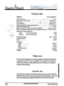
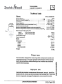
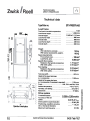
Technical data
Type/Order no.
BT1-FROOSTN.A50
Load frame
Test load in tensile/compression
~
680
~
5 kN
1,299mm
1.545to2.114mm
680 mm
856 mm
256 mm
650 mm
Load frame height.......................
Overall height
.............................
Load frame width ........................
T
Overall width ...............................
Load frame depth
.......................
Overall depth ..............................
~
~
Weight
With electronics console ..............
With typical accessories, approx.
..,.
~
~
Space requirements:
Pure contact area ........................
N
I
It)
Loadframe,area '.'
.'1;
~
""
...106cm2
5,564cm2
"."'"
Specific floor loading:
Related to the typical accessories
With 50% safety ...........................
Floor loading:
Related to the typical accessories
,
With 50% safety
"'
".."'
Test area width
150 kg
180 kg
'.'
1.70 kg/cm2
2.55 kg/cm2
0.03 kg/cm2
0.05 kg/cm2
440 mm
Height of the lower test area
1
w.o. accessories
1,058 mm
Height of the upper test area
w.o. accessories (Crosshead is required)
1,034 mm
Finish """"""""""""""""""""""'"
RAL 7011 and RAL 7038
Ambient temperature
+10 to +35 °C
Humidity, non-dewing
20 to 90 %
Noise level
67 dB(A)
Drive system
Crosshead speed .....................
Accuracy of the set
speed .. .....................................
Drive system's travel resolution
Operator's workplace
10
Positioning, repetition accuracy
(W.o. reverse of direction)
Maximum test frequency..........
Zwick technical documentation
~
I0
0,0005 to 3,000mm/min
0,03 % ofV~
0.041~m
< 1.0 ~m
0.5 Hz
04.03 I Tech IV2.7
~
~
AI
Ie
~
i
i
Technical
details
MTM T1-FROO5TN.A50
I0
~
k
i
go
S'
i
i
Identification
Materials testing machine
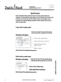
Identification
Each materials testing machine has two serial number plates as
standard. A large serial number plate is on the electronics console ands
a small one is on the rear of the machine base. An exception is the
single screw materials testing machines, each of these has only one
serial number plate.
Large serial number plate
Here is the CE sign for those materials testing
machines that have a declaration of conformity.
Manufacturer with address
Nominal value of the materials testing machine
Small serial number plate
Manufacturer with address
/'
Here is the CE sign for those materials testing
machines that have a declaration of conformity.
-
Order number = Machine type
Serial number/Year of construction
Nominal value of the materials testing machine
I0
~
k
i~
~
i
i
~
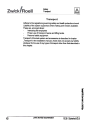
Safety
Materials testing machine
Your safety
This technical manual should make it easier for you to get acquainted
with the machine and to use its range of applications.
This technical manual contains important remarks on transporting the
materials testing machine correctly, safely and economically and on
installing, dismantling and storing it. Pay attention to these remarks. They
make it possible to increase the reliability and life span of the machine.
The instruction manual must be read and used by all persons authorised
to work at and with the machine.
The entire instruction manuals must always be available at the test
machine's installation site.
National regulations
Supplement the technical manual with instructions from national
regulations on accident prevention and environmental protection
Observe and adhere to:
-
Valid, binding regulations on accident prevention
- Recognised technical rules for safety and correct working
- Regulations on safety and health protection when preparing and using
-
working means
Instruction manuals
I0
;
i
I~
n
"
i
c
~
Zwick technical documentation
05.04/THlnhalt/V3.0
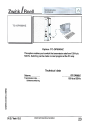
Document
Materials testing machine
General
In this section you can obtain data important for the materials testing
machine and obtain information on our company and its products.
Document:
Technical manual
Version:
Print date:
V3.0
November 2005
All rights reserved
I0
Tips, remarks and constructive criticism are welcome. Please direct
these to:
i~
Zwick GmbH & Co
Technische Ookumentation
August-Nagel-StraBe 11
0-89079 Ulm
~
i
~
c
'J
Fax: +49 - (0) 7305 - 200
Zwick technical documentation
~
r
05.04/ THlnhalt / V3.0
Index
13, 16, 21
Proximity switch
R
Remainingrisks ..........................
Riskofbuming ............................
Riskof frostbite...........................
Riskof injury...............................
Riskof slippage..........................
Riskofsquashing........................
Riskof trappingpartsof the body
.9
11
11
11
23
18
11
17
Rotating lead screws ...................
W
13
Warning signs ......................
Work
On laser light sources .....
Working
On hydraulic equipment ..
On pneumatic equipment
With electrical equipment
Working area ........................
Workplace ............................
22
23
23
...... 22
17, 18
15
.,":if
......
S
Safety
Devices"""""
'..".'
'
Gloves .........................................
Goggles
Safety devices
,
:',.,
Safety measures
Atoperation
................................
Before switching on .....................
Ear protectors .............................
Specimen holders
Safety notes.....................................
Safety remarks.................................
"
Serv'K:e
""
""""
'.."""
""..."".
13, 16, 17
20
20
13, 16
16
16
20
18
16
13
21
Setup ...............................................
Signal words ....................................
Specimen holders.............................
Spring tests ......................................
State of the art '.."..."'..."..."'
'.'.
19
.5
Supplements
.5
....................................
13
12
18
Symbols
Electrical voltage .........................
Laser beam .................................
Risk
ofbuming ............................
Risk of frostbite ...........................
Risk of injury ...............................
Risk of trapping parts of the body
11
11
11
11
11
11
I0
~
T
Tensile tests
Transport.....
J
18
.6
I
~
~
U
Usage
Improperuse
Properuse ...
i
i
8
7
Zwick technical documentation
01.02/ Silndex / V2.0
Safety
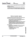
Cleaning
[4]"
.
Please adhere to the legal obligations for avoiding waste as well as
disposing and recycling it.
Water pollutants must not pollute the earth, and they must not gain access
to the sewer system I
Examples of water contaminating substances
Lubricants and oils
Hydraulic oils
Coolants
Cleansing fluids containing solvents
Collectthese pollutants in suitable containers. Transport, dispose of, etc.
pollutants in an environmentally safe manner.
Please take note of remarks on disposal on all applicable and relevant
safety data sheets. The enclosed safety data sheets are to be found in
section 13 "Certificates/Calibration reports"
Dispose of all replacement parts safely and in an environmentally safe
manner.
{
0
~
-'"
r
I
"
n
p
i
i
24
Zwick technical documentation
10.05/ Sicherheit / V2.9
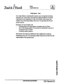
Safety
Safety
.
measures
and
[4J
notes
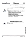
When working with electrical equipment
The leads from the mains cable(s) and mains input filters up to the input
of the main switch are under current even when the materials testing
machine is switched off.
Maintenance and corrective maintenance work on electrical equipment
must be carried out by competent and qualified electricians only!
Electrical equipment and systems should be checked regularly, at
least every 4 years, for proper functioning (BGV A3)
by qualified and competent electricians.
Please keep the switch console closed at all times! Access is only
permitted for electricians with keysltools!
Switch consoles/Housing for electrical equipment (Such as
electronic housing, motors) should never come into contact with
water nor steam (I.e. steam jet cleaners)!
When working on laser light sources
Only trained, competent and authorised personnel are to be allowed to
work on laser equipment.
I0
~
r
I
go
~
i
i
22
Zwick technical documentation
10.05/ Sicherheit / V2.9
[4]
Safety
Safetymeasures and notes
Safety goggles, safety gloves
Risk of injury!
Example:
Tests on specimen that shatter
Tests with jaw inserts that might shatter
Component testing
Everybody, even observers, must wear safety goggles if
potentially dangerous tests are being run (EN 166) and/or
protective gloves.
Temperature
Danger of burning or freezing!
Parts of the machine such as the motor can become very hot.
The outer parts of temperature chambers and other parts, e.g.
connectors, may become very hot or cold when testing with a
temperature chamber.
Never ever leave hot/cold specimen lying around unprotected.
Only work with heat resistant protective gloves.
Noise
Loud specimen break can lead to damage to your hearing.
Please use ear-protectors in such cases.
The materials testing machine doesn't emit any noise that
could damage your hearing. The noise levels for the
respective materials testing machines and their components
are to be found in section 2 "Technicalmanual"
I0
Laser extensometer
Safety goggles aren't necessary. Avoid looking into a laser
light source and never use optical instruments to look into
laser beams.
Working on laser equipment should only be done by
correspondingly trained service personnel.
20
Zwick technicaldocumentation
10.05/ Sicherheit / V2.9
~
i
I
~
i
i
Safety
Safety measures and notes
~
Working in the working area
Danger of trapping parts of the body.
Keep your hands away from the test area when the materials
testing machine is running.
Specimen holders, hydraulic/pneumatic
Danger of trapping parts of the body.
Keep your fingers away from between the gripping jaws.
Use a tool, e.g. tongs, for inserting specimen!
Tongs are available for hydraulic grips.
Please make sure that any pneumatic and/or hydraulic
equipment of, or for use with, the materials testing machine is
at zero pressure before you start to work with it.
..
I
Tensile tests: Risk of squashing
Danger of trapping parts of the body.
There's a danger of trapping parts of the body after test during
return to der initial position. There's a danger of squashing
parts of the body especially between specimen holders that
are close to one another, i.e. the free grip to grip separation is
very small.
You must wait until the test is ended and the crosshead has
stopped moving before attempting to access the working
area.
I0
~
Compression and flexure tests: Risk of squashing
Danger of trapping parts of the body.
There's a danger of squashing parts of the body during these
tests whilst the compression platens or flexure test elements
are in motion. Never ever attempt to access the space
between compression platens or flexure test elements with
parts of your body whilst a test is running.
Zwick technical documentation
10.05/ Sicherheit
V2.9
r
I
Safety
Safety measures and notes
Before
~
switching on
Please observe the following before switching the materials testing
machine on:
Only authorised persons may be allowed into the working area of
the materials testing machine
Check the all safety devices (Safety devices, limit switches,
proximity switches and EMERGENCY OFF button) for evident
malfunctions.
Check the materials testing machine for visible damage! Report
any determined damage immediately!
The materials testing machine must not be used at all if the following
(Exemplary) defects are detected:
Defects or damaged separating safety devices.
Defects or damaged pneumatic leads.
Defects or damaged hydraulic leads.
Defects must be rectified before putting the materials testing machine
into operation.
At operation
Gather information on how to react in case of defects or damage before
switching the materials testing machine on.
Non-observance
could lead to injury.
I0
EMERGENCY OFF button
In case of danger any movement of the materials testing machine must
be stopped immediately by hitting or pressing the red EMERGENCY
OFF button.
'"
~
i
t
go
n
"
j
i
16
Zwick technical documentation
10.05/ Sicherheit / V2.9
Safety
Instructions for the operating personnel
The test system must be operated by qualified and authorised
operating personnel only.
The operating personnel must have some knowledge of:
- Safe operation.
- Suitable safety clothing.
- Any potential risks emanating from the test system.
The operating personnel must be instructed with respect to work
safety and environmental protection as follows:
- Before the beginning of their work
- After any eventual alterations/amendments to the test system
however, at least
Annually
-
The operating personnel must know the safety remarks contained in
the instruction manual and adhere to them
The operating personnel wears suitable protective clothing (Safety
goggles/face shield, safety shoes, protectice gloves, tightly fitting
clothing, haimets for long hair).
Please pay attention to the following as a user of hydraulic test
systems:
Loss of oil could possibly occur during both operation or when the system
is idledue to leakage.It couldevenoccurduringmaintenancework. Loss
of oil couldcauseenvironmentalpollution(Groundwaterpollution)and
couldalso be the causeof accidents.
Please pay attentionthat hydrauliccomponentsare situatedwhere it
would cause no problems at all to accommodate the maximum quantity
of oil which could be lost due to leakage. Oil sumps or similar konnen or
specially built hydraulics-cellars can be used. Please make sure that
hydraulic oil cannot penetrate into the ground.
Please make sure that all valid rules and reugallations as well as laws
and guidelines on the handling and disposal of (Hydraulic) oil(s) are
strictly adhered to.
Zwick technical documentation
10.05/Sicherheit
/V2.9
I0
J
i
I
~
~
:1
i
Safety
Symbols and hit words
14]
Signal words in the instruction manual
The instruction manual marks functions which may contain risks of injury
for the operating personnel or danger for a device with the signal words
as indicated below. These functions may only by carried out by trained
operating personnel with due care and diligence.
Indicates a potentially hazardous situation
which, if not avoided, may result in minor or moderate injury.
I
0
~
r
I~
Safety remarks with the signal word "DANGER" or "WARNING" may also
contain hazards for test systems, accessories and the environment.
Zwick technical documentation
10.05/ Sicherheit / V2.9
~
i
Safe~
Preventivemeasures
r-:+:l
l~~J
Furthermore, each of our materials testing machines is equipped with an
EMERGENCY OFF button.
The safety device is used to protect the operator and the vicinity.
Never ever shut down or override the functions of safety devices:!
Checks and preventive measures
The following checks and preventive measures must be carried out independent of your running checks for any evident deficiencies.
Electrical equipment and systems should be checked regularly, at
least every 4 years, for proper functioning (BGV A3)
by qualified and competent electricians.
Please make regular visual checks of all hydraulic hoses. They must
be replaced immediately if any damage is detected. According to
DIN 20066 fluid technology, hoses hydraulic hoses should be
replaced every six years at the latest as a precautionary measure.
Recommendation
All safety devices (E.g. EMERGENCY OFF button, limit switches,
safety door, etc.) should be checked and maintained by an
authorised person:
- Immediately upon detection of damage
- Following maintenance work
- At least once a year
I0
_I
i
I.
~
i
i
10
Zwick technical documentation
10.05/ Sicherheit / V2.9
Safety
Impermissible use
~
Improper use
Any usage listed or exceeding the proper use is recognised as being
improper use. Zwick does not accept any liability whatever for damge
resulting from any application or use not included under proper use.
Liability is the sole responsibility of the user. The gurantee for the test
system expires.
Examples of impermissible use:
Amendments to the test system not agreed upon by Zwick
Use of the testing system in the sense of a production machine if
not agreed upon by Zwick
Overriding safety systems
-
Zwick does not acceptany liability for tools, appliances or devices
integrated by the user. Any necessary safety measures are then the sole
responsibility of the operator/user.
I0
~
i
.I
'.
~
i
i
Zwick technical documentation
10.05/ Sicherheit
V2.9
Safety
Transport
[4J
Transport
Adhere to the regulations governing safety and health protection at work
(Liability of the system supervisor) when making work means available.
These are, amongst others:
Instructing the employees
Proper use of transport means and lifting tackle
Personal safety equipment
Transport of the test system and accessories is described in chapter
"Transport" in the installation manual. Zwick does not accept any liability
whatever for the use of any types of transport other than that described in
this chapter.
I0
J
r
i.
~
i
f
6
Zwick technical documentation
10.05/ Sicherheit
V2.9
I0
I
r
I.
~
i
i
4
Zwick technical documentation
04.03/ Silnhalt / V2.5
Document
Materials testing machine
~
General
This section contains information that is important for maintenance and
service for your materials testing machine and the accessories.
The safety manual must be read and used by all persons authorised to
work at and with the machine.
Document:
Safety manual
Output:
V2.9
November 2005
Print date:
All rights reserved
I
0
Tips, remarks and constructive criticism are welcome. Please direct
~
theseto:
i
I
Zwick GmbH & Co
Technical documentation
August-Nagel-StraBe 11
0-89079 Ulm
Fax: +49
2
- (0) 7305
go
~
i
i
- 200
Zwick technicaldocumentation
04.03/ Silnhalt / V2.5
Product description
Materials testing machine
[VJ
Zwick materials testing machines can be put to universal use. They are
concipated for almost all test requirements for nationalen and international standards, as well as for a large part of the requirements as
described by a wide range of "in-house standards".
Thesematerials testing machines are not only for use in quality assurance
for rotine investigation, but also for research whereby test programs must
first be defined.
Overview:
Extensometer
MCE
Unit
{Measurement
Control
Materials testing machine
Electronics}
Communication
Environmental
simulation
interface
PC
.,
~.
Safety device
I0
~
k
Ito
The modular construction enables supplementary retrofits to be made
I
i
very easily.
10
~
Zwick technical documentation
05.04 Iident I V3.(J
~
Description of the company
Materials testing machine
Zwick Roell AG
I0
J
i
I
~
~
i
i
8
Zwick technical documentation
05.04/ldent / V3.0
~
Use of the instruction manual
Materials testing machine
The instruction manual is structured to the same repetitive pattern
The single chapters are compiled in the sequence:
- Materials testing machine
- Load cell
- Extensometer
- Power pack (hydraulic/pneumatic)
- Test tools
- Environmental test device
- Test accessories.
Exception is dismantling (See the example on this page).
Some parts of the manual may not be included in your manual as the
manuals are supplied for that equipment as per the configuration of your
materials testing machine. Some chapters don't require a detailed
description for certain parts.
The next diagram shows how a section in the instruction manual is
compiled, using the installation manual for a materials testing machine
with hydraulic power pack, test tools, extensometer and temperature
chamber as an example:
[Z]
Installation manual
i0
~
r
i
to
~
i
i
6
Zwick technical documentation
05.04/ldent/V3.0
.
[fI]~!,
Use of the instruction manual
Materials testing mach,ne
,
,
Should you resell your materials testing machine, you must also provide
you r customer with the instruction manual. The complete instruction
manual is an integral part of the materials testing machine.
Instruction manual's structure
Read through this short introduction and you'll be able to find the theme
that interests you more quickly as this introduction informs you where and
how you can find your way.
The instruction manual is split into different categories:
Important
for everybody
Section 1:
"Safety manual",
The contents must be known to everyone.
For the technicians
Section 3:
"Installation manual",
Aimed at personnel responsible for transport,
installation, dismantling, packing and storage,
Section 4:
"User manual".
Aimed at operating personnel and describes the
operation/operating elements of purchased
components.
Section 10 "Serviceand maintenancemanual".
Aimed at maintenance personnel with maintenance
intervalsas well as error rectification.
Section 11 "Circuit diagrams"
Aimed at maintenance and service personnel.
~
k
III
What everybody needs
Section 2:
i0
"Technical manual".
Contains the technical data,
'i1
Section 15 "Appendix".
Contains addresses and a maintenance order form.
Zwick technical documentation
05.04/ldent I V3.0
i
J
~
[j
Manufacturer:
Zwick GmbH & Co
August-Nagel-StraBe 11
0-89079Ulm
GenTlany
Customer
service:
ZwickService
August-Nagel-StraBe 11
0-89079 Ulm
Telephone:0730510-0
Hotline:
Supportline:
07305 10225
0190881988
Fax: 0730510200
Help for malfunctioning
Support for operation and
application
eMail:
Internet:
[email protected]
http:\\www.zwick.de
http:\\www.zwick.com
Further addresses from service and sales companies are listed in the appendix.
Document:
Version:
Print date:
Instruction manual "Materials testing machine"
is split into:
- Safety manual
- Technical manual
- Installation manual
- User manual
- Service and maintenance manual
See the respective manual
November 2005
Copyright (c) 2005 by Zwick GmbH & Co.
August-Nagel-Str.
11
0-89079 Ulm-Einsingen
i0
~
i
All rights reserved
Ito
We've done our best to make sure that this instruction manual is complete and free of
errors. Should you notice anything that is unclear in spite of this please inform us. Our
products are being continuously improved upon. Thus it may happen that some
statements in this manual don't always correspond to the latest state. Exact info can
be obtained by calling Zwick in Ulm if you're not entirely sure.
2
Zwick technical documentation
05.04/ldent/V3.0
.b>
i
i