1
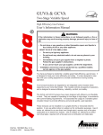
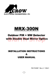
7-inch Digital Video Door Phone Quick Start Guide DPM-IP700 i Welcome Thank you for purchasing our product! This user’s manual is designed to be a reference tool for your system. ii Table of Contents 1 2 Framework ................................................................................................................................... 1 1.1 Front Panel .................................................................................................................... 1 1.2 Rear Panel..................................................................................................................... 2 Basic Operations ........................................................................................................................ 3 2.1 Multiple-media Communication Function ................................................................. 3 2.1.1 2.1.2 2.1.3 2.1.4 2.2 Call ........................................................................................................................... 3 Monitor .................................................................................................................... 5 Call History ............................................................................................................. 5 Contacts .................................................................................................................. 5 Information Search Function ...................................................................................... 6 2.2.1 Information .............................................................................................................. 6 2.2.2 Alarm Log ............................................................................................................... 6 2.3 System Setup ................................................................................................................ 7 2.3.1 2.3.2 2.3.3 2.3.4 2.3.5 2.3.6 2.4 Password Setting................................................................................................... 7 Background Setting ............................................................................................... 8 Display Setting ....................................................................................................... 8 Ring Setting ............................................................................................................ 9 Restore Default Setup .......................................................................................... 9 Project Setting...................................................................................................... 10 Home Security ............................................................................................................ 10 2.4.1 Security Setting.................................................................................................... 10 2.4.2 Home Appliances Control .................................................................................. 12 2.5 Tool ............................................................................................................................... 12 2.5.1 Clock ...................................................................................................................... 13 2.5.2 Calculator.............................................................................................................. 13 2.6 Unlock .......................................................................................................................... 14 2.6.1 Unlock During the Dial Process ........................................................................ 14 2.6.2 Unlock During the Communication ................................................................... 14 2.6.3 Unlock During the Monitor Status ..................................................................... 14 2.7 DND Function.............................................................................................................. 15 2.8 Turn off LCD ................................................................................................................ 15 iii 2.9 Other functions............................................................................................................ 15 2.10 Doorbell connection ................................................................................................... 16 3 Specifications ............................................................................................................................ 17 4 FAQ ............................................................................................................................................ 18 iv 1 Framework 1.1 Front Panel Please connect the device to the power socket; you can see the power indication light is on. After system booted up, you can see the front panel is shown as below. See Figure 2-1. 1 2 3 15 4 5 14 13 12 1 1 10 9 8 7 6 Figure 1-1 Please refer to the following sheet for detailed information. SN Name Function You can see this icon on the standby interface if you 1 Clock icon have set the clock. 2 Network connection icon It is to display current network connection status. 3 Time It is to display current time. 4 Menu button The main menu button. 5 Microphone Audio input. Click it to open the door when you are monitoring, 6 Unlock button calling or in the communication process. When there is an incoming call, click it to pick up the 7 Pick up button phone. 8 Monitor button Monitor the connected door station. 9 Lock LCD Lock the LCD, turn off or boot up the LCD. Click it to generate an emergency call to the 10 Emergency call button management centre. DND status indication The indication light is on (green) if the do-no-disturb 11 light status is enabled. Information indication The indication light is on (green) if there is any 12 light unread message. 1 13 14 15 Network indication light Power status indication light Shortcut menu The indication light is on (green) if the network connection is OK. The indication light is on (green) when the power connection is OK. Main menu button 1.2 Rear Panel The rear panel is shown as in Figure 1-2. Figure 1-2 Please refer to the following sheet for detailed information. SN Name Function 1 RJ-45 network port Connect to the Ethernet. 2 Power port Supply 12V DC power 3 RJ11 extension RJ11 extension There are 10 pins (from left to the right). 4 Alarm extension GND alarm 8 alarm 7 alarm 6 alarm 5 GND alarm 4 alarm 3 alarm 2 alarm 1 2 2 Basic Operations 2.1 Multiple-media Communication Function In the standby mode, click the button; you can go to the main interface. Click the “Call” button; you can see there are five function buttons: call, monitor, leave messages, contacts. See Figure 2-1. Figure 2-1 2.1.1 Call 2.1.1.1 Call Household Click the Call button; you can go to the call interface. See Figure 2-2. Please input the household number and then click the call button, you can call a resident. For those residents saved in the contacts, you can directly select the resident and then click the call button. Please note, you need to contact your local management centre for 8-digit room number. Figure 2-2 3 2.1.1.2 Call Extension Number Click the “Call extension” button; you can talk to the extension number. The interface is similar to the Figure 2-2. 2.1.1.3 Call Management Centre Click the “Management centre” button; you can talk to the management centre. The interface is similar to the Figure 2-2. 2.1.1.4 Contacts Click the “Contacts “button; you can go to the following interface. See Figure 2-3. Please select the household you want to call and then click the call button. The contacts operation includes add, modify, delete, delete all and etc. Figure 2-3 2.1.1.5 Call History The call history includes the missed call, received call, dialed phone and etc. Select one item in the list and then click the “Call” button, you can call the specified number. Click the Save button, you can save current phone to the contacts. The contacts also supports delete and delete all function. See Figure 2-4. Figure 2-4 4 2.1.2 Monitor In the main interface, select the multiple-media communication button and then select the “Monitor” button; you can view the video from the door station. See Figure 2-5. You can implement the following operations. Click the “Record” button; you can record the video from the monitor door station. The recorded files are saved in the monitor record. Please go to the Monitor record to view the detailed information. Click the “Snap” button; you can snap the picture from the monitor door station. Click the “Unlock” button; you can unlock the monitor door station. If there are several door stations, you can click the “Next channel” to view the video from the next door station. Figure 2-5 2.1.3 Call History In the main interface, click the “Multiple-media communication” button and the select the “Call history” button; you can see an interface is similar to Figure 2-4. 2.1.4 Contacts In the main interface, click the “Multiple-media communication” button and the select the “Contacts” button; you can see the following interface. Click “Add” button to add the resident information and then click the “Save” button, you can edit the address list. See Figure 2-6. 5 Figure 2-6 2.2 Information Search Function On the standby interface, click the button; you can go to the main interface. Click the”Information search” button; you can go to the information search interface. There are five buttons: information, video/audio record, monitor record, alarm log and visitors. All the information is listed by the time. The information indication light is on when there is unread message. The information indication light is off when the entire messages are read. Figure 2-7 2.2.1 Information Click “Info” button, you can view all information. It includes property advertisement, water and electricity bill, power off notice and etc. All the information issued is from the management centre. See Figure 2-8. Figure 2-8 2.2.2 Alarm Log Click the “Alarm log” button; you can view the alarm record of this station. See Figure 2-9. 6 Figure 2-9 2.3 System Setup On the standby interface, click the button; you can go to the main interface. Click the “Config” button. You can set the password, background, display, and ring, touch panel calibration, restore factory default setup, project installation and etc. You can set the corresponding parameters if necessary. See Figure 2-10. Figure 2-10 2.3.1 Password Setting The password setup interface is shown as in Figure 2-11. Here you can set general user password, door station unlock password, door station anti-hijack password. Please input the old password, and then input new password and confirm. Click the modify button, the password is successfully modified. Default password is “888888”. Please note the door station unlock password and door station anti-hijack password shall be verified by the management centre before they become valid. 7 Figure 2-11 2.3.2 Background Setting In this interface, you can set the favorite background image. Click the Modify button, the modification is successfully saved. See Figure 2-12. Figure 2-12 2.3.3 Display Setting In the display interface, you can set brightness, contrast, hue, screen saver waiting time, screen saver last time. Click the modify button to save current setup. See Figure 2-13. 8 Figure 2-13 2.3.4 Ring Setting In the ring setup interface, you can set the incoming call ring, alarm ring , clock ring and set the ring volume. See Figure 2-14. Figure 2-14 2.3.5 Restore Default Setup The system supports restore default setup function. Go to the Restore default setup interface and then click the OK button. Some items such as user password, anti-hijack password, door station password, alarm ring, incoming call ring, LCD parameter, and screen lock time, screen turn off time, and clock information will restore the factory default setup. See Figure 2-15. 9 Figure 2-15 2.3.6 Project Setting Please note this function is for system debug only. You need to contact our local project engineer for help. 2.4 Home Security On the standby interface, click button to go to the main interface. Click the “Home security” button, you can go to the home security interface. The system provides many home security modes such as home, outgoing, sleep mode. It also provides system setting and home appliances control function and etc. See Figure 2-16. You can set the home security mode according to your actual requirements. You need to select the area you want to set and then enable. Then you need to go to the Scene mode interface to select the mode and implement the corresponding setup to enable. You can see the mode icon at the right top corner. Figure 2-16 2.4.1 Security Setting 10 In the Indoor mode, select the area you want to set and then check the button to enable. See Figure 2-17. Please note you need to go to the following interface to set the area. Figure 2-17 Go to the system setting interface and then select the “Indoor mode”. Click the “Modify” button. See Figure 2-18. Figure 2-18 Click the “Scene mode” and then select the “Home mode”. Now you need to set to enable the arm function. You can see the corresponding mode icon at the top right corner. See Figure 2-19. 11 Figure 2-19 2.4.2 Home Appliances Control Click the “Home appliances control” button; you can see the following interface. Here you can control the lights. See Figure 2-20. Figure 2-20 2.5 Tool On the standby interface, click button to go to the main interface. Click the “Tools” button; you can go to the tool interface. Here you can see the aux function such as calculator, clock, calendar, user’s manual and etc. 12 Figure 2-21 2.5.1 Clock Time is synchronized from door station. Firstly pls set a proper time on your door station. Figure 2-22 2.5.2 Calculator In the “Tools” interface, click the “Calculator” button; you can go to the following interface. See Figure 2-23. You can implement the calculation here. Figure 2-23 13 2.6 Unlock 2.6.1 Unlock During the Dial Process During the dial process, you can open the e-lock of the door station remotely. There is a 15second for you to confirm the unlock operation. During these 15 seconds, the video is properly displayed. After the 15 seconds countdown, system returns to the standby interface. Figure 2-24 2.6.2 Unlock During the Communication During the communication process, you can open the e-lock of the door station remotely. There is a 15-second for you to confirm the unlock operation. During these 15 seconds, the communication is OK and the video is properly displayed. After the 15 seconds countdown, the phone automatically hangs up. Figure 2-25 2.6.3 Unlock During the Monitor Status During the monitor status, you can open the e-lock of the door station remotely. There is a 15second for you to confirm the unlock operation. During these 15 seconds, the video is properly displayed. After the 15 seconds, the video automatically disappears. 14 2.7 DND Function This series product supports the do-not-disturb (DND) function. You can enable this function to shield the incoming ring. On the standby interface click the button, you can go to the DND setup interface. There are total six options: 0-hour/1-hour/2-hour/4-hour/8-hour/24-hour. You can enable or disable this function. You can set the corresponding valid time after you enabled this function. 2.8 Turn off LCD The system supports LCD off function. On the standby interface, click the Lock LCD button (Button 9 in Figure 1-1) the LCD turns off. On the non-standby interface, click the Lock LCD button twice, the LCD turns off. You can click the Lock LCD button to boot up the LCD if current screen is off. 2.9 Other functions On the standby interface, click the , you can see there are some aux functions such as information search, call, monitor and etc Here you can also quickly use the information search, call, monitor function and etc. See Figure 2-26. Figure 2-26 15 2.10 Doorbell connection Pls connect a door bell to the first alarm port. After that set “Doorbell Ring” type according figure 2-27. Figure 2-277 16 3 Specifications Video Video compression standard Audio Bidirectional talk Screen Dimensions Resolution Alarm Input Others Power Power consumption Working environments Dimensions Weight H.264 Dual-way bidirectional talk Color 7-inch TFT LCD 800*480 Cable, 8-channel DC 10~15V Standby<1W,work<5W 0~50℃. Humidity: 20~80%RH 220mm*153mm*23mm(L*W*H) 500g 17 4 FAQ Q: My indoor monitor screen is black and the indication light is off. What shall I do? A: Please check the power socket connection is OK or not. Q: My indoor monitor can not generate a call and implement the monitor function. The network indication light is off. What shall I do? A: Please check the network cable connection is OK or not. Q: When the door station is calling the indoor station, but I can not hear the ring from the indoor station. What shall I do? A: Please check your do-not-disturb (DND) mode has been enabled or not. Please check the DND indication light is on or not. Q: My indoor monitor ring volume is too low. What shall I do? A: Please check the ring volume setup is OK or not. Q:I have some problems, I am not so sure or I can not fix. A:Please contact your local retailer for help. Note: This document is for reference only. Slight difference may be found in the user interface. All the designs and software here are subject to change without prior written notice. If there is any uncertainty or controversy, please refer to the final explanation of us. Please visit our website or contact your local service engineer for more information. 18