1
Software Testing in Context
Graham G. Thomason
Appendix to the Thesis “The Design and
Construction of a State Machine System
that Handles Nondeterminism”
Department of Computing
School of Electronics and Physical Sciences
University of Surrey
Guildford, Surrey GU2 7XH, UK
July 2004
© Graham G. Thomason 2003-2004
Summary
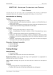
This paper presents a broad approach to testing – an approach that theoretically could be
adapted and applied to a typical software project. It is a condensation of what appear to be the
best state-of-the-art practical testing techniques. We cover module testing, integration testing,
and system testing; white-box testing and black-box testing; automated test execution and
automated test generation.
The purpose of the paper is to situate state-based-testing in a broad testing context.
A word of caution is in place. Owing to the variety of techniques presented, one would be
unwise to attempt them all on any one project, as this could easily lead to an overload of
tooling and lack of focus on key testing issues for the particular project in hand.
ii
© Graham G. Thomason 2003-2004
Contents
1.
A general testing approach ............................................................................................... 1
1.1
Code checking ......................................................................................................... 2
1.2
Module testing......................................................................................................... 3
1.3
Integration testing.................................................................................................... 7
1.4
System testing ......................................................................................................... 8
2. Non-functional testing ...................................................................................................... 9
3. Automated test execution ............................................................................................... 10
4. Automated test generation .............................................................................................. 17
4.1
State-based testing ................................................................................................. 17
4.2
Decision tables ...................................................................................................... 19
4.3
Cause-effect graphing (CEG) ................................................................................ 27
4.4
Syntax testing ........................................................................................................ 36
4.5
Orthogonal arrays .................................................................................................. 42
4.6
Other model-based testing ..................................................................................... 42
4.7
Random testing ..................................................................................................... 42
4.8
Summary of automated test generation ................................................................. 42
5. Abbreviations ................................................................................................................. 43
5.1
Testing-related abbreviations ................................................................................ 43
5.2
Other abbreviations used ....................................................................................... 43
6. References ...................................................................................................................... 44
© Graham G. Thomason 2003-2004
iii
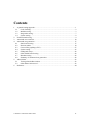
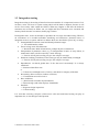
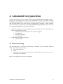
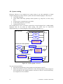
1. A general testing approach
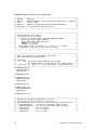
The V-model for the software development life-cycle is well-known. The testing phases of
this model are shown in Figure 1.
System
test
tests
Requirements
tests
System
design
Integration
test
tests
Module
design
Module
test
checks
Coding
Figure 1.
Code
checking
V-model and testing
The V model identifies various kinds of testing activity, and each has its own emphasis. We
consider the aims of and techniques for each form of testing, starting at the bottom of the V
model and working up the right-hand side:
Code checking in general: Static analysis can reveal bad coding style and possible
pitfalls. Dynamic techniques can check for memory leaks and can provide code
coverage, such as statement coverage, described in more detail later.
Module testing: The question to be answered is: Does the implementation correspond
to the design? Modules are usually single functions, or a small number of tightly
coupled functions designed against a single specification. Exercise code statements
and branches. Use code instrumentation to check for coverage of these. Also include
a memory leak check in the tests. Module testing is typically white-box testing - we
have a knowledge of the code structure and use it to guide us in designing test cases,
and we have detailed controllability and observability of the module.
Integration testing: The question to be answered is: Is the design internally
consistent? Exercise interfaces between modules. Measure call-pair coverage (i.e.
every call and every return from it). Integration testing is typically black-box testing some modules may even be only available as object code, and the only way we can
test the integrated system is via the published interfaces.
System testing. The question to be answered is: Does the system satisfy the project
requirements? This will typically be a black-box testing activity, since the
requirements do not normally specify internal controllability and observability, but
© Graham G. Thomason 2003-2004
1
rather the operations and their outputs which to which the end-user has access. For
some kinds of system, a part of system testing will be volume testing. For example, a
set-top box will need to be tested with large quantities of MPEG streams, and a
Global Positioning System will need to be tested with large quantities of sampled
radio-front-end (intermediate frequency) satellite data.
Tests suites are best structured, where possible, as a set of individually self-sufficient test
cases, defining their own pass/fail criterion (rather than e.g. comparing output with that of
previous runs). Some tests will address robustness under error situations.
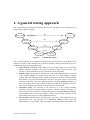
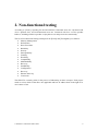
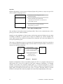
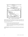
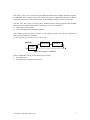
For each form of testing, it may be advantageous not to test against the specification directly,
but to produce a test specification, and test against that. In this way, we admit that we are not
testing everything (or every combination of things), but we do make explicit what
combinations of things we are testing.
Functional
Specification
Figure 2.
Test
Specification
Test
Scripts
The Principle of a Test Specification
In addition to functional testing, there is non-functional testing, which is largely a form of
system testing. This is considered in chapter 2. Further chapters address test automation.
We now consider the aims of each form of testing in a little more detail.
1.1 Code checking
At the bottom of the V model is coding. As code is produced (or perhaps upgraded from
prototype to production status), it should be subjected to some static analysis. This could be:
Automated static analysis, e.g. for C and C++, by the [QAC] product. This analysis
will reveal poor coding style and many potential bugs. It also provides code
complexity metrics. Experience shows that complex code in terms of its branching
and looping structure (having a high cyclomatic complexity metric) is much more
liable to have bugs than one which is less complex.
Code reviews by peers. This is often regarded as being as valuable as testing.
Code may also be subject to dynamic analysis. The following can be used when testing:
Memory leak and array bounds checking (using e.g. [Purify]).
Code instrumentation for statement or branch coverage checking.
Data flow testing. A tool tracks the use of variables, and reports on suspect use.
2
© Graham G. Thomason 2003-2004
We discuss code instrumentation and data flow testing in little more detail in section 1.2.
1.2 Module testing
Modules are tested against a module specification, and we aim to cover all statements or all
branches in our tests. There is a saying that if in your tests you haven't executed any lines of
code, you might as well rip them out of the product, because they are a good as defective.
Statement coverage is essential, branch coverage is desirable, but there are various levels of
detail of branch coverage, which we briefly discuss. Then we give some advice on how
module tests could be designed.
Code coverage is obtained by instrumenting the code, so that when it is executed, apart from
executing its own function, it also produces a log or trace of what code was executed.
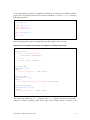
Example (from [McCabe])
The program is regarded as segments (between potential branches or function calls), which
are numbered by a node number. The node numbers are recorded on execution.
Uninstrumented
if (Getstate() > 0) {return Fred(); }
Instrumented
if ( (_mcrepco2(1662,1663,(GetState() > 0) != 0) ) )
{return Fred();}
The call to _mcrepco2 contains the evaluated condition in the third argument, so that the
relevant node number (the first or second argument) can be logged according to whether it is
true or false, and so the resultant boolean value can be returned into the if statement.
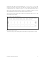
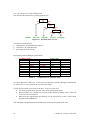
A table is then produced with coverage results, e.g.
Module Name
LsdSyncDec::GetResource
LsdSyncDec::OpenSession
Table 1.
# Branch
8
11
# Covered
5
5
% Covered
62.5
45.5
Example of a coverage table
Before we discuss forms of statement and branch coverage, we must discuss a factor that
interferes with measurement of some of them. C and many other languages use short-circuit
evaluation of boolean expressions. Short-circuit evaluation skips evaluating operands where
they do not contribute to the expression result. The problem that arises is
Not all combinations of boolean terms are relevant - but in the context of short-circuit
evaluation we know that, and do not count them against us in terms of the coverage
percentage.
Boolean operands could be function calls that may have side effects. So they cannot
safely be evaluated in instrumented code if they would not be evaluated under normal
uninstrumented circumstances. So we cannot measure some forms of coverage.
© Graham G. Thomason 2003-2004
3
In the examples below, our typical condition is
if (x==0 || y==0 ||z==0) ...
(For simplicity we do not call functions here).
The naming for code coverage is not universally standardised; we take frequently used names.
The most commonly met forms of coverage that one could attempt to cover are:
1. Statement coverage. This is achieved if the if statement is executed at all.
2. BDC: Branch decision coverage
Full coverage is obtained by any expressions that make the entire boolean expression
true and false.
3. BCC: Branch condition coverage. The individual terms (not the variables) in the
boolean expression must be made true and false at some time. So x==0 must be true
and must be false on occasions, as must y==0 and z==0. But we are not concerned
about combinations, or even whether the branch is taken.
4. BDC/BCC: The union of BDC and BCC.
5. MC/DC: Modified condition decision coverage. Each boolean operand must
individually affect the outcome of the decision. Four combinations would suffice for
values of x, y, and z (using t=true, f=false, x=don't care): (f,f,f), (t,f,f), (f,t,f), (f,f,t). In
general this requires n+1 tests for n boolean operands. Under short-circuit evaluation,
this form of coverage can be measured on the understanding that it really is done in
the context of short circuit evaluation. So (f,f,f), (t,x,x), (f,t,x), (f,f,t) gives full
coverage. However, with all x=t in practice, say, it would not necessarily give full
coverage if the terms in the expression were re-ordered, though with all x=f it would.
MC/DC coverage in the short-circuit context is called masking-MC/DC and in the
long-circuit context it is called unique cause MC/DC.
6. BCCC: Branch condition combination coverage. This requires that the boolean
operands take on all values in all combinations, i.e. (f,f,f), (f,f,t), (f,t,f), (f,t,t), (t,f,f),
(t,f,t), (t,t,f), (t,t,t). In general this involves 2 n tests for n boolean operands. Under
short-circuit evaluation, this form of coverage can be sensitized for, but not all
measured.
7. LCSAJ: Linear Code Sequence And Jump coverage. This may appear to be like
branch testing, but it differs in that it requires that loops are executed in ways that
branches do not require.
8. Path coverage. For full coverage, all paths through the program are taken. The
enormous number of paths in a typical module makes this impracticable.
4
© Graham G. Thomason 2003-2004
In practice BDC is often chosen where testing time is very limited. BCC is very weak on its
own, as it does not force branch decision. BDC/BCC appears to be offered by many
inexpensive tools. MC/DC is potentially very powerful (it exposes the weakness of the
above-mentioned coverage criteria) but takes quite some work (but so does BDC/BCC).
MC/DC is required as part of the US Department of Defense standard DO-178B. BCCC is
excessive in most cases, and impracticable with short-circuiting languages such as C. LCSAJ
is powerful and should be feasible in many cases. Not all are supported by all tools.
Data flow coverage
This form of coverage is not based on statements, but on data flow as variables are Defined
(created, initialized, or written to in an assignment), Used (as a Predicate in a condition, or in
a Calculation in the right hand side of an assignment), and Killed (e.g. by going out of scope).
A coverage requirement might be that every path from Definition to Use is exercised. Many
more paths are useful. Anomalies are looked for such as DK (why define and kill without
using?) or KU (definitely a bug - an undefined value is being used). Reference: [Beizer, ch.5].
There are many other forms of coverage - see for example [BCS Sigist].
How should module tests be designed?
The module under test will often be isolation tested, where all modules it calls are stubbed.
Stubbing is replacing real modules by small modules with pre-cooked return values,
preferably controllably by the test script. This gives more control over the module than when
it is not stubbed.
Sometimes there is opportunity for automatic test generation, especially for state-based
testing, decision table testing and cause-effect graphing (discussed later). But often module
tests will be hand crafted. The tests will typically be matter of supplying various sets of
parameter values in a function call. Global data may also play a role. Parameter values should
be divided into equivalence classes, based on critical boundaries. Then ‘grazing’ values
should be taken in and just out of each equivalence class. For example, if an equivalence class
is the range -9..-4 (inclusive), test at least with values -10, -9, -4, -3. Correct error handling for
out-of-range values should be checked.
Specific points of attention for numerical systems
Calculation-intensive applications have the potential for many numerical errors. Points of
attention could be
Finding all divisions in expressions and looking for possible sensitization of division
by zero
Looking for overflow / underflow / sign flip - perhaps in mid-expression - (perhaps
detect it by assertion)
Looking for int / unsigned / long int / unsigned long int / float / double / long double
mixes in expressions and review them (maybe static analysis can help).
Looking for all subtractions in expressions, and anticipate insufficient precision. The
result of (large number)-(another similarly large number), e.g 123456789.12-
© Graham G. Thomason 2003-2004
5
123456789.13, producing a very small number, is subject to great loss of precision,
because much of the available precision was used up in storing the parts of the
numbers that were subtracted away.
Subjecting the module to massive feeds of data (volume testing) around critical
expressions where it is claimed that dangerous values of variables cannot occur, with
dense assertions in the codes; also continue to look for values indicative of
overflow/underflow/sign flip (loss of precision due to subtraction might be hard to
detect by assertion). The data might be:
o random data
o artificial data representing unusual circumstances.
After the tests have been designed, scripted and run the, the coverage figures can be analysed,
and ways should be devised to sensitise for branches that were not taken. Occasionally, extra
test software (such as special stubbing) is required to do this, because the error condition
might be hard or impossible to sensitize from calling parameters alone.
Code coverage targets
What coverage targets should be set? Safety critical industries would require 100% MC/DC
coverage. A paper claiming the experimental effectiveness of MC/DC is [Dupuy]. However,
it does require considerably more effort than BDC/BCC, which are more commonly taken as
norms. It is sometimes infeasible to sensitize for coverage certain parts of code, especially
some error handing code, except by artificially forcing it.
6
© Graham G. Thomason 2003-2004
1.3 Integration testing
Integration testing is the testing of interfaces between modules. It is important, because if it is
not done, errors will occur in system testing which will be hard to diagnose, because it will
not be clear exactly what caused the failures. What may happen is that after the defective
statement was executed, no failure was yet caught and more statements were executed, and
memory blocks became overwritten, destroying evidence.
In integration tests, we do not attempt to reproduce the coverage of module testing. What we
do concentrate on is module-to-module interfacing and interaction. Potential causes of
integration errors in a system, and how to address them, are described in [Trew 99], covering:
Incompatibilities between actual and formal parameter ranges.
Test with boundary values.
Errors in large scale state behaviour
Reach all states. Make all transitions, perhaps all pairs of transitions
Interpretation of parameter values, (e.g. in interpretation of units, of array offsets, in
enumerated values, a defect caused by a make file bug)
Exercise all call pairs (tooling can give the call pair coverage)
Parameter ordering. Parameters of the same type may be inadvertently exchanged
Exercise all call pairs (tooling can give the call pair coverage)
Dependencies on shared global data. Is the data used consistently? Is it always
initialised?
Structured data-flow tests
or
Volume test with high levels of activity, and check for integrity of the data
Re-entrancy (direct recursion, indirect recursion).
Visualisation tools will reveal it
Race conditions
(State-based) test under all preconditions.
Ensure design (and code) employs a handshake
Deadlock
Rigorous design inspections
Volume testing.
It is seen that exercising call pairs (client-server calls) and state-based testing can play an
important role, as does design/code inspection.
© Graham G. Thomason 2003-2004
7
1.4 System testing
System testing addresses the question of whether the system meets the customer's or project
manager's requirements. Even perfect module and integration testing, with 100% coverage
figures, will not protect against swathes of missing functionality. System testing is against
requirements and system level analysis documents, and obviously the approach is very
application specific. The use of a test specification (see Figure 2) is particularly useful here.
Many tests of a fully integrated system should be centred around the user - i.e. they should be
use cases.
Use cases
Use cases are part of UML. For the UML baseline, see [Catalysis, Ch. 4]. Use cases are
important in system testing, because, if well chosen, they exercise the software in the way it is
likely to be used in practice. Use cases are part of the [PHASST] approach in Philips, where
they are described as follows:
A use case describes the system's behaviour under various conditions as the system
responds to a request from its users. The system user, primary actor in use case
terminology, interacts with the system to achieve some goal. Each use case is a high
level description of the group of scenarios which may be triggered when a particular
set of conditions holds. It also includes a set of conditions that are valid when the
sequence of events associated with any of the scenarios in the set is completed.
8
© Graham G. Thomason 2003-2004
2. Non-functional testing
According to [Evans], reporting for the BCS SIGiST, functional areas are concerned with
what a product does, and non-functional areas are concerned with how well the product
behaves, including whether a product is enjoyable to use and perceived as trustworthy.
The list of non-functional testing techniques from [Evans] and [TestingStds] is as follows:
Memory Management
Performance
Stress Procedure
Reliability
Security
Interoperability
Usability
Portability
Compatibility
Maintainability
Recovery
Installability
Configuration
Recovery
Disaster Recovery
Conversion
The SIGiST is currently (2003) in the process of elaborating on these concepts. Each project
needs to review which of the above are applicable and how to address them in the light of its
own context of use.
© Graham G. Thomason 2003-2004
9
3. Automated test execution
The techniques described here apply across different levels of testing (module, integration,
system testing).
Testing should normally be automated where possible. Humans become weary of e.g.
repeatedly following written test instructions manually and checking output by eye. But even
a collection of diverse test programs can be difficult to manage. The best kind of test suite is
one in which
All tests are called in a uniform way
Every test calls the Implementation Under Test (IUT) and examines the IUT output
directly in the script.
Every test defines its own pass/fail criterion
Every test logs the test name or number and a pass or fail indication.
If possible, the test script supplies values to stubbed modules, so that all relevant data
to a test comes from the test script, and is not distributed among special stub routines.
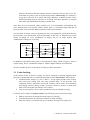
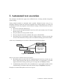
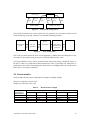
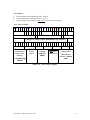
A basic way of automating test execution is illustrated in the following figure:
Stub
Stub
Script
Test Harness
Implementation
Under Test
Test Report
Figure 3.
Automated test execution
There are two levels at which tests may be scripted:
Hard-linking the test script to the IUT (Implementation Under Test). In this case, the
tests are direct function calls and tests on return values or on global data. A tool that
supports this kind of testing, and also gives coverage data, is Cantata [Cantata].
Communicating with the IUT at the executable level. A good public domain tool for
communicating via Standard Input and Standard Output is DejaGnu. [DejaGnu].
Examples of Cantata and DejaGnu in use are now given.
10
© Graham G. Thomason 2003-2004
Cantata
Cantata [Cantata] is a commercial test harness from IPL. It is suitable for C testing. There is a
sister product called Cantata++ which is suitable for C or C++ testing, which is more actively
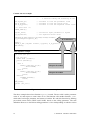
promoted by the company. We show what is essentially involved in writing test cases in
Cantata.
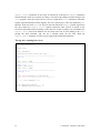
In the example below, we are testing some function myfunc which takes an integer
parameter and returns an integer. This function calls another function, which is artificially
called stub, since it will be stubbed. The figure below shows a Cantata test script, including
stubs for the stubbed function, and instructions on how the stub is to be used on each call to it.
© Graham G. Thomason 2003-2004
11
Cantata test case example
extern int myfunc(int);
// IUT Declaration:
//
a function taking and returning an int
int myfunc_P1;
int R_myfunc;
int E_R_myfunc;
// Variable to hold the parameter value
// Variable to hold the return value
// Variable to hold the expected return value
/*** Test Case ***/
START_TEST(2);
myfunc_P1=10;
E_R_myfunc=20;
// Initialize input parameter to myfunc
// Set expected return value
EXECUTE_BY_REF("myfunc","stub#1;stub#1;stub#2");
R_myfunc=myfunc(myfunc_P1);
IUT called here
DONE();
CHECK_S_INT ("myfunc return", R_myfunc, E_R_myfunc);
END TEST();
Stub definition example
int stub (int p1)
{
int ret_val;
START STUB ("stub1");
switch (ACTION)())
{
case 1:
CHECK_U_INT("p1",p1,30);
retval=TRUE;
break;
case 2:
CHECK_U_INT("p1",p1,40);
retval=FALSE;
break;
default:
ILLEGAL_ACTION();
break;
}
END_STUB();
return (ret_val);
}
Figure 4.
this part for stub#1
this part for stub#2
Cantata test case example
The above example shows how function myfunc is tested. The test calls it with a parameter
value of 10, and expects a return value of 20. The function calls another function, stub,
which takes an integer parameter and returns a boolean. We stub this function by defining
pre-cooked return values (TRUE and FALSE) based on the calling parameter. The stub
definition allows us to check that calling parameter is 30 or 40 depending on which occasion
12
© Graham G. Thomason 2003-2004
the stub was called. The test case itself specifies (by "stub#1;stub#1;stub#2") that
the stub is expected to be called 3 times, twice under case 1 conditions, then once under case
2 conditions. Under case 1 conditions we expect stub to be called with parameter value 30
and we return the pre-cooked value TRUE. Under case 2 conditions we expect stub to be
called with parameter value 40 and we return the pre-cooked value FALSE.
Any deviations from the expected values in the stub or in the return value of myfunc will
cause the test to report a failure.
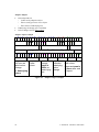
The test report is of the following format:
=======================================================================
Test Script Checks Checks Checks Stubs
Paths
Assertions Status
Errors Passed Failed Warning Failed Failed Failed
----------------------------------------------------------------------PTE
0
0
0
0
0
0
0
PASS
001
0
2
0
0
0
0
0
PASS
002
0
3
1
0
0
0
0
>>FAIL
ANS
0
2
0
1
0
0
0
PASS
-----------------------------------------------------------------------Total
0
7
1
1
0
0
0
>>FAIL
=======================================================================
PTE stands for Pre-Test Errors.
ANS stands for analysis check warning (the user can define a coverage measure as a check).
© Graham G. Thomason 2003-2004
13
DejaGnu
DejaGnu [DejaGnu] is a layer on top of Expect [Expect-DL], which is a layer on top of TCL
(Tool Command Language) [TCL].
Provides test suite management and
Pass/Fail logging
DejaGnu
Expect
Allows spawning of programs and
communication with them via standard I/O.
Also handles timeout.
TCL
An interpretative scripting language,
designed for general use
Figure 5.
TCL, Expect and Deja Gnu
TCL and Expect can both be learnt from [Expect-DL]. There is also a detailed book on TCL,
[TCL], by its creator, John Ousterhout.
DejaGnu is well established on Unix Systems, and has been ported to Windows for use under
CYGWIN [CYGWIN]. A separate port of Expect to Windows (by Gordon Chaffee) also
exists. Both versions are pointed to by [Expect-Nist]. DejaGnu was used on the Philips G+4
set-top box platform project.
The essence of DejaGnu testing is to spawn the IUT (Implementation Under Test) and talk to
its via standard input and standard output. If the IUT does not respond within a certain time, a
timeout can catch this in DejaGnu.
spawn the IUT
DejaGnu
script
send to standard input
Test report
expect (patterns) from
standard output;
also handle timeout
IUT
Figure 6.
DejaGnu
DejaGnu communicates with an executable program, the IUT or a program relaying I/O to
and from the IUT. So the IUT could be on the same computer as DejaGnu, or on another
machine. In the latter case, DejaGnu would spawn e.g. a serial line program or a socket
program communicating with the actual IUT. This scheme is suitable for testing the IUT on a
target board, providing the necessary glue code is in place. DejaGnu (being in essence
EXPECT) can spawn more than one program and control them independently if necessary.
14
© Graham G. Thomason 2003-2004
A calc demonstration program is supplied with DejaGnu. It would not be confused with the
proper Unix calc program, because of its verbose commands, add and multiply. It has the
following behaviour:
% calc
calc: add 2 3
5
calc: add 1 2 3
Usage: add #1 #2
calc: multiply 3 4
12
calc: multiply 2 4
12
calc: quit
%
Note that the program produces a prompt after any other output. Notice its bug!
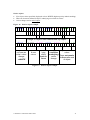
Excerpts from a DejaGnu Test Script (as supplied - it could be improved)
spawn calc
expect_after {
-re "\[^\n\r]*$prompt$" {
fail "$test (bad match)"
}
timeout {
fail "$test (timeout) "
}
}
set test add1
send "add 3 4\n"
expect {
-re "7+.*$prompt$"
{pass $test}
}
set test add2
send "add 1 2 3\n"
expect {
-re "Usage: add #1 #2.*$prompt$"
}
set test multiply2
send "multiply 2 4\n"
expect {
-re "8.*$prompt$"
}
{pass $test}
{pass $test}
The script first spawns the calc program. The calc program will then run internally,
without a window, obtaining input from Expect and writing output to Expect. The
© Graham G. Thomason 2003-2004
15
expect_after statements in the script are effectively extensions to expect statements
discussed below. Each test consists of setting a test name and sending an ASCII string to the
calc program. Then the script waits for (expects) output from calc, which may match the
regular expression defined. If this happens, the test is passed by a call to the DejaGnu pass
function. If the text from calc for any test does not match the expect regular expression,
but does match the expect_after regular expression, then control is passed to the
associated statements before returning to the next test. In this example, two possibilities for
expect_after have been defined: one for when some text at least ending in the calc
prompt has been obtained, and one for a timeout when all else fails. Both the
expect_after situations are fails, but are logged with a different annotation.
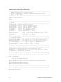
The log after running these tests
=== calc tests ===
spawn calc
calc: Running
./testsuite/calc.test/calc.exp ...
-------------------------------------add 3 4
7
calc: PASS: add1
-------------------------------------add 1 2 3
Usage: add #1 #2
calc: PASS: add2
-------------------------------------multiply 2 4
12
calc: FAIL multiply2 (bad match)
-------------------------------------=== calc Summary ===
# of expected passes
# of unexpected failures
16
2
1
© Graham G. Thomason 2003-2004
4. Automated test generation
We have discussed how the test framework must support automated test execution (as far as
possible) for all testing phases. Under some circumstances it may be possible to deploy
automated test generation as well. The generated tests may be generated as a batch, in which
case the same testing set-up can be used as for automated test execution. A more advanced
form of automated test generation is on-the-fly automated test generation, where what later
tests are generated depends on the results earlier tests.
Automatic generation of tests is possible where the specifications are in a formalism with
which a test generator can work:
o state-based tests (derived from a state-transition diagram)
o decision tables
o cause-effect graphing
o syntax testing
Another form of automated testing is
o random testing
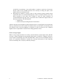
4.1 State-based testing
The state behaviour of a system is described by a statechart, as in the dynamic model of
UML. The elements of the model are
states (in a hierarchy)
events
transitions (these connect source state(s) to target state(s) on an event; we say an
event triggers a transition).
Below is an example from a smart-card manager:
© Graham G. Thomason 2003-2004
17
Disconnected
Disconnect
Connect
Connected
No_Card
RemoveCard
InsertCard
Card
Error
MiscellaneousErrors
ErrorHandled
Card OK
Configuring
Configure
OK
Ready
Send
DscDataTransmit
Sending
Reset
OK
Sent
Resetting
DscDataReceived
Retrieving
DscDataReceived
Figure 7.
Statechart of a smart-card manager
Statecharts like this are valuable in pinning down the specifications and in providing a good
handle for testing, whether by hand-crafted tests or by automatic test generation. To test
against a statechart like this, we need to at least cover all transitions. Deeper coverage could
be obtained by requiring transition pairs.
To automate the process, we need two key programs (best kept separate)
o A test generator that says what events are to be processed
o A test oracle to the tests that says what the new state is (or what outputs were
expected). The oracle program may entail a language to describe the statechart, a
compiler and a run-time machine engine for that language. STATECRUNCHER
[StCrMain] is such an oracle.
For white-box testing, we are able to examine the state of the IUT and test against states. For
black box testing, we test against outputs. The figure below illustrates white box state-based
testing.
18
© Graham G. Thomason 2003-2004
compare
Test Script
set
state
process
event
get
state
set
state
State Behaviour
Model (SBM)
Figure 8.
process
event
get
state
Implementation
Under Test (IUT)
State based testing basics
The [TorX] architecture has a more explicit test case generator in a tool chain as follows (with
TorX terminology at the top, and more conventional terminology below).
Explorer
Primer
Driver
Adapter
state machine
oracle
test case
generator
test harness
glue code to
communicate
with IUT
Figure 9.
IUT
TorX architecture
The TorX tool chain forms the basis of investigations by Philips Research Bangalore in the
use of the TorX toolchain using STATECRUNCHER [StCrMain] as the oracle.
Very large numbers of tests can be generated using state-based testing, though the nature of
the tests is often very unlike that of hand-crafted ones. This is especially true where there is
parallelism in the model. The technique has been effective in finding defects in a DVD system
and in the G+4 set-top box platform.
4.2 Decision tables
Decision tables directly relate combinations of inputs to multiple outputs.
Inputs are called the condition stub.
Outputs are called the action stub.
Table 2.
Rule (e.g. from
Requirements
Specification)
Decision table example
Condition stub
C1
C2
C3
Action stub
A1
A2
true
true
true
false
true
false
x
x
true
false
false
true
true
false
true
false
© Graham G. Thomason 2003-2004
true
true
false
x
19
Use x for "don't care" in the condition stub.
The decision table represents a (usually pruned) tree:
C1
yes
no
C2
no
yes
C3
no
(A1,A2)
(yes,no)
(no,yes)
yes
(no,no) (yes,yes)
Figure 10. Decision table as a tree
Check the decision table for
completeness (no undetermined outputs)
consistency (no contradictions)
good sense (review activity)
In principle generate all input combinations
Condition stub
C1
C2
true
true
true
true
true
false
true
false
false
x→true
false
x→true
false
x→false
false
x→false
Table 3.
C3
true
false
x→true
x→false
x→true
x→false
x→true
x→false
Action stub
A1
true
false
false
false
true
true
true
true
A2
true
false
true
true
false
false
false
false
Combinations in a decision table
An x does not mean “don't care” to the tester!! In principle generate all input combinations,
(so whever an x occurs, generate the true and false value).
Use the decision table as an oracle to the tests. To generate the tests:
For small decision tables, the test cases can be generated by hand.
Decision tables are a simple case of CEG (Cause Effect Graphing), and a CEG tool
can be used (see section 4.3).
Rules from the requirements specification can be expressed in a rule or logic based
program such as PROLOG.
The following example illustrates how PROLOG can be used to generate the tests.
20
© Graham G. Thomason 2003-2004
Robot Arm Example1
A robot has three kinds of gripper:
magnet
sucker
parallel fingers
The following rules to determine how to pick up an object:
A magnet can only be used on ferrous objects
A magnet requires an accessible upper surface
A sucker requires a smooth object
A sucker requires an accessible upper surface
Parallel fingers require a rough object
Parallel fingers require accessible parallel faces
1
This example was suggested to the author for an exercise with an expert system shell by an engineer
at Agfa-Gevaert in Antwerp in 1985.
© Graham G. Thomason 2003-2004
21
PROLOG program to derive test cases from rules
/*--------------------------------------------------------------------*/
/* Module:
robot1.pl
*/
/* Author:
Graham Thomason, Philips Research Laboratories, Redhill */
/* Date:
10 Jun, 1999
*/
/* Purpose:
Example of unpruned decision table generation
*/
/*
*/
/* Copyright (C) 1999 Philips Electronics N.V.
*/
/*--------------------------------------------------------------------*/
/*--------------------------------------------------------------------*/
/* Representation of an object
*/
/* ===========================
*/
/*
An object is of the format [AUS,APF,FERROUS,SMOOTH]
*/
/*
AUS = Accessible Upper Surface
*/
/*
APF = Accessible Parallel faces
*/
/*
FERROUS= is ferrous
*/
/*
SMOOTH = is smooth
*/
/*
Each item in this list can be 't' (true) or 'f' (false)
*/
/*
if SMOOTH=f, then we say the object is rough
*/
/*--------------------------------------------------------------------*/
/*--------------------------------------------------------------------*/
/* Rules for picking up by different robot arms
*/
/* Self explanatory predicate names
*/
/*
*/
/* Parameters
*/
/*
X
(In) The object being examined for picking
*/
/*
For representation of the object, see comment above
*/
/*
VAL (Out) ='y' (yes) or 'n' (no) according to the pickability
*/
/*--------------------------------------------------------------------*/
pickByMagnet(X,y):hasAccUpSurf(X),
isFerrous(X),
!.
pickByMagnet(X,n).
pickBySucker(X,y):hasAccUpSurf(X),
isSmooth(X),
!.
pickBySucker(X,n).
pickByFingers(X,y):hasAccParFaces(X),
isRough(X),
!.
pickByFingers(X,n).
/*--------------------------------------------------------------------*/
/* Testing for different properties in object
*/
/* ==========================================
*/
/* The predicates take an object as their parameter and succeed if:
*/
/*
hasAccUpSurf(X):
if X has an accessible upper surface
*/
/*
hasAccParFaces(X): if X has an accessible parallel faces
*/
/*
isFerrous(X):
if X is ferrous
*/
/*
isSmooth(X):
if X is smooth
*/
/*
isRough(X):
if X is rough
*/
22
© Graham G. Thomason 2003-2004
/*--------------------------------------------------------------------*/
hasAccUpSurf(X):X=[t,_,_,_].
hasAccParFaces(X):X=[_,t,_,_].
isFerrous(X):X=[_,_,t,_].
isSmooth(X):X=[_,_,_,t].
isRough(X):X=[_,_,_,f].
/*----------------------------------------------------------------*/
/* Generate all objects (on backtracking)
*/
/*
generates [f,f,f,f], [f,f,f,t], [f,f,t,f], etc.
*/
/*----------------------------------------------------------------*/
obj([AUS,APF,FERROUS,SMOOTH]):ausVal(AUS),
/* accessible upper surface value */
apfVal(APF),
/* accessible parallel faces value */
ferrousVal(FERROUS), /* ferrous value
*/
smoothVal(SMOOTH).
/* smooth value
*/
ausVal(X):tfVal(X).
apfVal(X):tfVal(X).
ferrousVal(X):-tfVal(X).
smoothVal(X):- tfVal(X).
tfVal(f).
tfVal(t).
/*--------------------------------------------------------------------*/
/* main loop
*/
/*
Writes abbreviated keywords vertically
*/
/*
AUS=Accessible Upper Surface (object has)
*/
/*
MAG=Magnet (object is pickable pickable by)
*/
/*
etc.
*/
/*--------------------------------------------------------------------*/
go:write(' A A F S M S F'),nl,
write(' U P E M A U I'),nl,
write(' S F R O G C N'),nl,
fail.
go:obj(X),
/* loop over all objects */
pickByMagnet(X,PBM),
pickBySucker(X,PBS),
pickByFingers(X,PBF),
write(X),tab(1),write(PBM),tab(1),write(PBS),tab(1),write(PBF),nl,
fail.
go.
© Graham G. Thomason 2003-2004
23
Output (with minor reformatting to facilitate annotation)
| ?- go.
Object Properties
Accessible upper surface
Accessible parallel faces
Ferrous
Smooth
f = property is false
t = property is true
Gripper possibilities
Magnet suitable
Sucker suitable
Parallel fingers suitable
A A F S
U P E M
S F R O
[f,f,f,f]
[f,f,f,t]
[f,f,t,f]
[f,f,t,t]
[f,t,f,f]
[f,t,f,t]
[f,t,t,f]
[f,t,t,t]
[t,f,f,f]
[t,f,f,t]
[t,f,t,f]
[t,f,t,t]
[t,t,f,f]
[t,t,f,t]
[t,t,t,f]
[t,t,t,t]
yes
M S F
A U I
G C N
n
n
n
n
n
n
n
n
n
n
y
y
n
n
y
y
n
n
n
n
n
n
n
n
n
y
n
y
n
y
n
y
n = no, this gripper is not suitable
y = yes, this gripper is suitable
n
n
n
n
y
n
y
n
n
n
n
n
y
n
y
n
| ?-
Figure 11. Robot arm output
24
© Graham G. Thomason 2003-2004
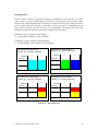
Karnaugh maps
Decision tables can also be represented as grids or spreadsheets (with 2 inputs) or as cubes
(with 3 inputs - but then separate planes are drawn) or as hypercubes for more inputs. These
diagrams are called Karnaugh maps. Adjacent cells with the same output value, but with at
least one input value held constant, reveal where a group of outputs is not dependent on all
inputs, and so showing where decision logic can be simplified. The figure below shows the
Karnaugh map for the robot arm, with colour coding to show grouping.
INPUTS: 4 binary variables (values t and f)
[AccUppSurf, ParFaces, Ferrous, Smooth]
OUTPUTS: 3 binary variables (values y and n)
[CanUseMagnet, CanUseSucker, CanUseFingers]
AccUpSurf=f, ParFaces=f
Inputs: [f, f, Ferrous, Smooth]
Smooth
f
t
AccUpSurf=f, ParFaces=t
Inputs: [f, t, Ferrous, Smooth]
Smooth
f
t
Ferrous
Ferrous
f
nnn
nnn
f
nny
nnn
t
nnn
nnn
t
nny
nnn
AccUpSurf=t, ParFaces=f
Inputs: [t, f, Ferrous, Smooth]
f
t
f
nnn
nyn
t
ynn
yyn
Smooth
Ferrous
AccUpSurf=t, ParFaces=t
Inputs: [t, t, Ferrous, Smooth]
f
t
f
nny
nyn
t
yny
yyn
Smooth
Ferrous
Figure 12. Karnaugh map
© Graham G. Thomason 2003-2004
25
From the Karnaugh map a decision table with don't cares can be constructed. The same
colour code as in the Karnaugh map is used below. Where 2 Karnaugh map cells form a
group, there will be one don't care, and where 4 cells form a group, there will be 2 don't
cares.
Condition
Action
Upper
Surface
f
Parallel
Faces
f
Ferrous
Smooth
Magnet
Sucker
x
x
n
n
Parallel
Fingers
n
f
t
x
t
n
n
n
f
t
x
f
n
n
y
t
x
t
t
y
y
n
t
x
f
t
n
y
n
t
f
f
f
n
n
n
t
f
t
f
y
n
n
t
t
f
f
n
n
y
t
t
t
f
y
n
y
Table 4.
Robot gripper decision table
Decision tables are a feed-forward technique. They are applicable where there is no obvious
memory in the logic, in contrast to state-based testing where states represent memory so that
the same event can have a different effect at different times because of the state. However, it
is possible to model simple state models as decision tables, where parallel states become
condition stub items, the event becomes another condition stub item, and the action stub items
are the new states.
26
© Graham G. Thomason 2003-2004
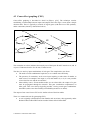
4.3 Cause-effect graphing (CEG)
Cause-effect graphing is described in detail in [Myers, p.56]. The technique consists
establishing a relationship between inputs and outputs where the logic is more than a simple
decision table. There is typically a network of logical gates (with their own CEG symbols),
under constraints (shown by dotted lines below).
A
X1
B
T
(and)
O
C
(one)
X2
J
F
Z
(and)
(and)
R
(requires)
K
G
(or)
H
X3
P
{
(or)
Q
Y
R
(nand)
S
Figure 13. A CEG
The constraint one above indicates that exactly one of the inputs B and F must be true, and G
requires H indicates that for G to be true, H must be true.
The idea is to test key input combinations of each gate. The complexities arise from:
The need to avoid combinatorial explosion, so to combine tests efficiently.
The presence of constraints, such as one input requiring a truth-value of another to
make sense. For example if one input is (x>0) and another is (x>6), it is not possible
to have the first true and the second false.
Observability issues. If intermediate nodes are not observable, the output of a gate
must be propagated through the network. This puts sensitization requirements on
other gates. This is not always logically possible - leaving certain gate combinations
untestable (unless extra observability/controllability measures are taken).
The output of test cases from a CEG tool is similar to that of decision tables.
There is a commercial tool for generating CEGs:
A tool originally called SoftTest from Bender and Associates, then apparently under
Borland called Caliber-RBT and now under Nohau called Caliber-RM.
© Graham G. Thomason 2003-2004
27
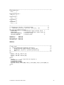
The following pages show how CEGs can be used to test the colour of a teletext object1.
Teletext objects are used to overwrite parts of a teletext page, but with quite complex rules to
govern the colour of the new text.
We take specifications from the standard (ETS 300 706, May 1997), paragraph 13, page 98.
Example of an object overwriting underlying text:
T H E
F A S T
L A Z Y
D O G
A N D
T H E
L A Z Y
D O G
A N D
One application of teletext objects is to place an advertisement in a certain place on a set of
pages, without the need to re-code the pages individually.
There are 3 kinds of object, plus underlying text, with highest-to-lowest priority as follows:
Passive
Adaptive
Active
Underlying text
We consider the 3 kinds of object in turn.
1
The test cases are for illustrative purposes. Absolute accuracy cannot be guaranteed, though care has
been taken with them, as, due to changing testing priorities, these tests have not actually been deployed.
28
© Graham G. Thomason 2003-2004
Active Objects
Colour change affects underlying text (“AND”)
Until underlying text changes colour, (“CAT”)
Colour change stays in effect to end of row (not end of object range)
Active object example
b THE
FAST
DOG
AND r CAT gRAN
LAZY
COW
FOX
p
I N
SAT
y
--range of object cells addressed by object-THE
LAZY
COW
AND
FOX
SAT
I N
blue
blue
pink
pink
red
yellow
yellow
Object does
not have an
initial colour
change
Object sets
a new
colour
-> Underlying
colour
Colour
change
stays in
effect
Underlying Active object sets
text sets
a new colour
new colour
This stays in
effect to end of
row
Figure 14. Active object example
© Graham G. Thomason 2003-2004
29
Adaptive Objects
Colour depends on
Colour set by adaptive object
Else as set by previous active object
Else colour of underlying text,
Underlying col change gets overridden
Colour changes end at end of object
Adaptive object example
b THE
FAST
DOG
AND r CAT gRAN
LAZY
COW
FOX
p
I N
SAT
y
--range of object cells addressed by object-THE
LAZY
COW
AND
FOX
SAT
I N
blue
blue
pink
pink
pink
yellow
green
Object does
not have an
initial colour
change
Object sets Colour
a new
change
colour
stays in
effect on
under-lying
-> Underlying
text
colour
Object
overrides
underlying
colour
change
Object sets a
new colour.
Does not remain
in force after end
of object
Figure 15. Adaptive object example
30
© Graham G. Thomason 2003-2004
Passive objects
If no object colour specified, displayed colour=WHITE (highest priority inherits nothing)
Where no character defined in object, underlying text retains its colour.
Colour changes end at end of object
Figure 16. Passive object example
b THE
FAST
DOG
AND r CAT gRAN
LAZY
COW
FOX
p
I N
SAT
y
--range of object cells addressed by object-THE
LAZY
COW
AND
FOX
SAT
I N
white
pink
blue
pink
yellow
green
blue
Object does
not have an
initial colour
change
Object sets
a new
colour
->WHITE
Underlying
colour
back in
force
Object
Object sets a new
overrides
colour
underlying
Does not remain
colour
in force after end
change
of object
Figure 17. Passive object example
© Graham G. Thomason 2003-2004
31
SoftTest Source of the Teletext Object CEG
/*----------------------------------------------------------------------*/
/* Module: TutTxtObj.ceg - Teletext objects
*/
/* Author: Graham Thomason, Philips Research Laboratories, Redhill
*/
/* Date:
28 May, 1999
*/
/*----------------------------------------------------------------------*/
TITLE 'Teletext Objects'.
NODES
/*----------------------------------------------------------------------*/
/* CAUSES
*/
/*----------------------------------------------------------------------*/
CharBeforeObj = 'Char is before any object'.
CharAfterPAS = 'Char is after a PASSIVE object'.
CharAfterADP = 'Char is after an ADAPTIVE object'.
CharAfterACT = 'Char is after an ACTIVE
object'.
CharInPAS =
'Char is in a PASSIVE object'.
CharInADP =
'Char is in an ADAPTIVE object'.
CharInACT =
'Char is in an ACTIVE
object'.
ExplicitObjChar =
UnderlyingColChange =
ObjColSet =
'Char is explicitly overwritten in the object'.
'Underlying text changes colour under the object'.
'Object has set colour'.
/*---------------------------------------------------------------------*/
/* Intermediate Nodes
*/
/*---------------------------------------------------------------------*/
AfterObjDispColUnder = 'Char after object- Display in underlying col'.
AfterObjDispColObj =
'Char after object- Display in object colour'.
InObjDispColUnder = 'Char in object- Display in underlying col'.
InObjDispColObj =
'Char in object- Display in object colour'.
InObjDispColWhite = 'Char in object- Display in white'.
/*---------------------------------------------------------------------*/
/* Effects
*/
/*---------------------------------------------------------------------*/
DispColUnder = 'Display the char in the underlying colour'.
DispColObj
= 'Display the char in the last colour set by the object'.
DispColWhite = 'Display the char White'.
/*---------------------------------------------------------------------*/
/* Constraints
*/
/*---------------------------------------------------------------------*/
CONSTRAINTS
ONE (CharBeforeObj,
CharAfterPAS,CharAfterADP,CharAfterACT,
CharInPAS,CharInADP,CharInACT).
MASK
MASK
MASK
MASK
(CharBeforeObj,ExplicitObjChar,UnderlyingColChange,ObjColSet).
(CharAfterPAS,ExplicitObjChar).
(CharAfterADP,ExplicitObjChar).
(CharAfterACT,ExplicitObjChar).
/*---------------------------------------------------------------------*/
/* Relations
*/
/*---------------------------------------------------------------------*/
RELATIONS
AfterObjDispColUnder:CharAfterPAS
32
© Graham G. Thomason 2003-2004
OR CharAfterADP
OR (CharAfterACT AND NOT ObjColSet)
OR (CharAfterACT AND
ObjColSet AND UnderlyingColChange).
AfterObjDispColObj:CharAfterACT AND ObjColSet AND NOT UnderlyingColChange.
InObjDispColUnder:(CharInACT AND
ObjColSet AND
UnderlyingColChange)
OR (CharInACT AND NOT ObjColSet)
OR (CharInADP AND NOT ObjColSet)
OR (CharInPAS AND
ObjColSet AND NOT ExplicitObjChar)
OR (CharInPAS AND NOT ObjColSet AND NOT ExplicitObjChar).
InObjDispColObj:(CharInACT AND ObjColSet AND NOT UnderlyingColChange)
OR (CharInADP AND ObjColSet)
OR (CharInPAS AND ObjColSet AND ExplicitObjChar).
InObjDispColWhite:CharInPAS AND NOT ObjColSet AND ExplicitObjChar.
DispColUnder:-CharBeforeObj OR AfterObjDispColUnder OR InObjDispColUnder.
DispColObj:AfterObjDispColObj
OR InObjDispColObj.
DispColWhite:-InObjDispColWhite.
/* -----[End of script] ----*/
© Graham G. Thomason 2003-2004
33
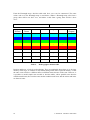
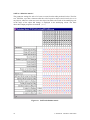
SoftTest “definition matrix”
The parameter settings for each of 15 tests are seen from the table produced, below. The first
test, TEST#01, says that a character after the end of a passive object (and so not before or in
any object), where no colour was set in the object, but where the colour of the underlying text
in the range of the object did change, is displayed in the underlying colour. The three
observable output properties are marked {obs}.
Figure 18. SoftTest definition matrix
34
© Graham G. Thomason 2003-2004
Limitations of SoftTest & CEGs
SoftTest is not a test harness
It does not claim to be.
The tests are also output as an ASCII file and can be converted to a scripting language
for use with a test harness.
In SoftTest, the number of tests is so highly optimized that it may fail to generate tests
that distinguish two inputs. For example if there is an input A to one gate, and B to
another, we may find that A and B are always set to true and false together.
CEGs are just one approach to systematic testing. They are not likely to be sufficient on
their own, and should be supplemented by other forms of testing.
© Graham G. Thomason 2003-2004
35
4.4 Syntax testing
Reference: [Beizer, ch 9] explains how syntax testing is not only applicable to formal
computer languages, because software systems often have hidden languages. These may be
a user input language
a data format with many (perhaps nested) options (e.g. bmp files, avi files, mpeg
files)
an inter-process communication convention
an API calling sequence convention
communication protocols
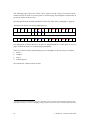
Our example below is for C, but many systems that are not languages like C exhibit hidden
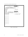
languages that can be tested by syntax testing. The syntax may be represented
diagrammatically as a railroad diagram, which defines the grammar, e.g.
type specifier
void
char
int
etc
structure or
union specifier
structure or union specifier
identifier
struct
union
{
identifier
struct
member
declaration
}
structure member declaration
type specifier
declarator
bit field declaration
Figure 19. Syntax graph - a bit of C
Test generation possibilities
Generate legal productions of the grammar and feed them to the IUT.
Mutate the grammar, generate productions of that, filtering them out if they happen to
also be parsable by the original grammar, feed these to the IUT and check that they
are recognized as error situations.
36
© Graham G. Thomason 2003-2004
The oracle, if any, must come from some additional information, perhaps manually supplied,
or embedded in the grammar. Even if no oracle to the tests is supplied, the tests have value in
testing the robustness of the system. Value can be added by putting assertions in the code.
We now show how syntax coverage can be obtained using a Prolog program. The example
illustrates how Prolog Definite Clause Grammars can serve two purposes:
Obtaining a parse of input
Generating productions from the grammar
The example generates sentences where several simple sentences can also be conjoined to
make one long sentence of the kind:
the boy likes the girl and the girl eats a pear and ...
Sentence
conjunction
sentence
simple
sentence
Figure 20. Syntax - a sentence
There is additional code to prevent sentences of the type
the A likes the A
the A likes the B and the A likes the B
© Graham G. Thomason 2003-2004
37
Listing
/*--------------------------------------------------------------------*/
/* Module:
sentence.pl
*/
/* Author:
Graham Thomason, Philips Research Laboratories, Redhill */
/* Date:
10 Jun, 1999
*/
/* Project:
S/W Testing:
*/
/* Purpose:
Example of syntax-based test generation
*/
/*
*/
/* Copyright (C) 1999 Philips Electronics N.V.
*/
/*--------------------------------------------------------------------*/
/*--------------------------------------------------------------------*/
/* EXTERNALS used by this module
*/
/*
ggtlib:io_pp
*/
/*--------------------------------------------------------------------*/
/*--------------------------------------------------------------------*/
/* NonTerminals
*/
/* ============
*/
/*--------------------------------------------------------------------*/
/*--------------------------------------------------------------------*/
/* sentence
*/
/*
recursive!!
*/
/*
we prevent sentences of the type
*/
/*
[A likes B ... and A likes B]
*/
/*--------------------------------------------------------------------*/
sentence(Y,Z):/* non DCG goal supplies default parameters */
sentence(1,Y,Z,[]).
sentence(DEPTH,[sentence,S1])-->
simple_sentence(S1).
sentence(DEPTH,[sentence,S1,C|RESTLIST])-->
simple_sentence(S1),
conjunction(C),
{(NEWDEPTH is DEPTH+1)},
{( (NEWDEPTH =< 3 ) ; (NEWDEPTH > 3,!,fail) )},
sentence(NEWDEPTH,S2),
{(S2=[_|RESTLIST])},
{(gn_not(gn_member(S1,RESTLIST)))}.
/*------------------------------------------------------*/
/* simple_sentence
*/
/*
we prevent [a Z likes a Z] type of sentence
*/
/*------------------------------------------------------*/
simple_sentence([simple_sentence,NP,VP])-->
noun_phrase(NP),
verb_phrase(VP),
{(NP=[_,_,N],N=[_,NW],
VP=[_,_,NP2],NP2=[_,_,N2],N2=[_,NW2],
NW\=NW2)}. /* not the same noun in both places */
/*----------------------------*/
/* noun_phrase
*/
/*----------------------------*/
noun_phrase([noun_phrase,A,N])-->
article(A),
noun(N).
/*----------------------------*/
/* verb_phrase
*/
/*----------------------------*/
verb_phrase([verb_phrase,V,NP])-->
38
© Graham G. Thomason 2003-2004
verb(V),
noun_phrase(NP).
/*-------------------------------------------------------------------*/
/* Terminals
*/
/* =========
*/
/*-------------------------------------------------------------------*/
article([article,A])-->
{(article(A))},
[A].
article(the).
/* article(a). */
noun([noun,N])-->
{(noun(N))},
[N].
noun(boy).
noun(girl).
/* noun(cherry). */
/* noun(pear). */
/* noun/3 */
/* noun/1 */
verb([verb,V])-->
{(verb(V))},
[V].
verb(knows).
verb(likes).
conjunction([conjunction,C])-->
{(conjunction(C))},
[C].
conjunction(and).
/* conjunction(but). */
/*---------------*/
/* simple tests */
/*---------------*/
tterm:-tarti,tnoun,tverb,tconj.
tarti:-article(P,[X],[]),write(P),tab(1),write(X),nl,fail.
tarti.
tnoun:-noun(P,[X],[]),write(P),tab(1),write(X),nl,fail.
tnoun.
tverb:-verb(P,[X],[]),write(P),tab(1),write(X),nl,fail.
tverb.
tconj:-conjunction(P,[X],[]),write(P),tab(1),write(X),nl,fail.
tconj.
tnp1:-noun_phrase(P,X,[]),io_pp(P),tab(1),write(X),nl,nl,fail.
tnp1.
tnp2:-noun_phrase(P,X,[]),
tnp2.
tab(1),write(X),nl,
fail.
tvp1:-verb_phrase(P,X,[]),io_pp(P),tab(1),write(X),nl,nl,fail.
tvp1.
tvp2:-verb_phrase(P,X,[]),
tvp2.
tab(1),write(X),nl,
fail.
tss1:-simple_sentence(P,X,[]),io_pp(P),tab(1),write(X),nl,nl,fail.
tss1.
© Graham G. Thomason 2003-2004
39
tss2:-simple_sentence(P,X,[]),
tss2.
tab(1),write(X),nl,nl,fail.
tsen1:sentence(1,P,X,[]),write(P),nl,io_pp(P),tab(1),write(X),nl,nl,fail.
tsen1.
tsen2:sentence(1,P,X,[]),tab(1),write(X),nl,fail.
tsen2.
/*----------------[end of module sentence.pl]---------------------*/
Coverage Output
| ?- tsen2.
[the,boy,knows,the,girl]
[the,boy,likes,the,girl]
[the,girl,knows,the,boy]
[the,girl,likes,the,boy]
[the,boy,knows,the,girl,and,the,boy,likes,the,girl]
[the,boy,knows,the,girl,and,the,girl,knows,the,boy]
[the,boy,knows,the,girl,and,the,girl,likes,the,boy]
[the,boy,knows,the,girl,and,the,boy,likes,the,girl,and,the,girl,knows,the,boy]
[the,boy,knows,the,girl,and,the,boy,likes,the,girl,and,the,girl,likes,the,boy]
[the,boy,knows,the,girl,and,the,girl,knows,the,boy,and,the,boy,likes,the,girl]
[the,boy,knows,the,girl,and,the,girl,knows,the,boy,and,the,girl,likes,the,boy]
[the,boy,knows,the,girl,and,the,girl,likes,the,boy,and,the,boy,likes,the,girl]
[the,boy,knows,the,girl,and,the,girl,likes,the,boy,and,the,girl,knows,the,boy]
[the,boy,likes,the,girl,and,the,boy,knows,the,girl]
[the,boy,likes,the,girl,and,the,girl,knows,the,boy]
[the,boy,likes,the,girl,and,the,girl,likes,the,boy]
[the,boy,likes,the,girl,and,the,boy,knows,the,girl,and,the,girl,knows,the,boy]
[the,boy,likes,the,girl,and,the,boy,knows,the,girl,and,the,girl,likes,the,boy]
[the,boy,likes,the,girl,and,the,girl,knows,the,boy,and,the,boy,knows,the,girl]
[the,boy,likes,the,girl,and,the,girl,knows,the,boy,and,the,girl,likes,the,boy]
[the,boy,likes,the,girl,and,the,girl,likes,the,boy,and,the,boy,knows,the,girl]
[the,boy,likes,the,girl,and,the,girl,likes,the,boy,and,the,girl,knows,the,boy]
[the,girl,knows,the,boy,and,the,boy,knows,the,girl]
[the,girl,knows,the,boy,and,the,boy,likes,the,girl]
[the,girl,knows,the,boy,and,the,girl,likes,the,boy]
[the,girl,knows,the,boy,and,the,boy,knows,the,girl,and,the,boy,likes,the,girl]
[the,girl,knows,the,boy,and,the,boy,knows,the,girl,and,the,girl,likes,the,boy]
[the,girl,knows,the,boy,and,the,boy,likes,the,girl,and,the,boy,knows,the,girl]
[the,girl,knows,the,boy,and,the,boy,likes,the,girl,and,the,girl,likes,the,boy]
[the,girl,knows,the,boy,and,the,girl,likes,the,boy,and,the,boy,knows,the,girl]
[the,girl,knows,the,boy,and,the,girl,likes,the,boy,and,the,boy,likes,the,girl]
[the,girl,likes,the,boy,and,the,boy,knows,the,girl]
[the,girl,likes,the,boy,and,the,boy,likes,the,girl]
[the,girl,likes,the,boy,and,the,girl,knows,the,boy]
[the,girl,likes,the,boy,and,the,boy,knows,the,girl,and,the,boy,likes,the,girl]
[the,girl,likes,the,boy,and,the,boy,knows,the,girl,and,the,girl,knows,the,boy]
[the,girl,likes,the,boy,and,the,boy,likes,the,girl,and,the,boy,knows,the,girl]
[the,girl,likes,the,boy,and,the,boy,likes,the,girl,and,the,girl,knows,the,boy]
[the,girl,likes,the,boy,and,the,girl,knows,the,boy,and,the,boy,knows,the,girl]
[the,girl,likes,the,boy,and,the,girl,knows,the,boy,and,the,boy,likes,the,girl]
yes
| ?-
40
© Graham G. Thomason 2003-2004
Example of a parse
| ?sentence(P,[the,boy,likes,the,girl,and,the,girl,knows,the,boy]),io_pp(P).
sentence
simple_sentence
noun_phrase
article
the
noun
boy
verb_phrase
verb
likes
noun_phrase
article
the
noun
girl
conjunction
and
simple_sentence
noun_phrase
article
the
noun
girl
verb_phrase
verb
knows
noun_phrase
article
the
noun
boy
P =
[sentence,[simple_sentence,[noun_phrase,[article,the],[noun,boy]],[verb_phra
se,[verb,likes],[noun_phrase,[article,the],[noun,girl]]]],[conjunction,and],
[simple_sentence,[noun_phrase,[article,the],[noun,girl]],[verb_phrase,[verb,
knows],[noun_phrase,[article,the],[noun,boy]]]]]
| ?-
Code for the above pretty print formatter is as in [Clocksin, p.81].
© Graham G. Thomason 2003-2004
41
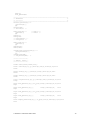
4.5 Orthogonal arrays
Suppose a routine needs testing with 4 parameters, (A, B, C, and D), each of which can take 3
values (1, 2, and 3). Exhaustive testing would require running 34=81 tests. But suppose we
find it adequate that all pairwise combinations of parameter values are taken. A table can be
found satisfying this with 9 entries of values of the 4 parameters as follows:
ABCD
1111
1223
1332
2122
2231
2313
3133
3212
3321
For pairwise coverage as above we speak of orthogonal arrays of strength 2. If we had
required that all triples of parameters should be covered for all combinations of values, the
strength would be 3 and so on. See also [Sloane]; the above array is equivalent to the one at
http://www.research.att.com/~njas/oadir/oa.9.4.3.2.txt.
4.6 Other model-based testing
Of the UML models, the dynamic model (state-based testing) is probably the most amenable
to automated testing. But use cases, message sequence diagrams, collaboration diagrams etc.
are also being used to derive tests. The [Agedis] project addresses model based testing
including such models. There is also a very rich website on model-based testing maintained
by Harry Robinson, with UML-based testing featuring prominently, [Robinson].
4.7 Random testing
Random testing can also be useful. In this case there is no precise oracle to the tests.
However, by densely larding the code with assertions (which act as oracles in a way), the tests
have value in testing the robustness of the system.
4.8 Summary of automated test generation
Automated test generation requires formal specifications such as a UML model, a decision
table, a cause effect graph, or the grammar rules of a language. Large numbers of tests can be
generated. State based testing has proved to be particularly effective in finding defects in
practice. Sometimes the techniques, which could be used for automated test generation, can
be applied by hand (e.g. for a small statechart or decision table).
42
© Graham G. Thomason 2003-2004
5. Abbreviations
5.1 Testing-related abbreviations
BCC
BCS
BDC
BCCC
CEG
IUT
LCSAJ
MC/DC
PHASST
QAC
SIGiST
TCL
Branch Condition Coverage
British Computer Society
Branch Decision Coverage
Branch Condition Combination Coverage
Cause Effect Graphing
Implementation Under Test
Linear Code Sequence and Jump (coverage)
Modified Condition / Decision Coverage
Philips Approach to Structured System Testing. See [PHASST]
Probably: Quality Assessment for C. See [QAC]
Special Interest Group in Software Testing
Tool Command Language
5.2 Other abbreviations used
API
GNU
GUI
MPEG
UML
Application Programmer Interface
Gnu's Not Unix - see http://www.gnu.org
Graphical User Interface
Moving Picture Experts Group
Unified Modelling Language
© Graham G. Thomason 2003-2004
43
6. References
STATECRUNCHER documentation and papers by the present author
[StCrMain]
The Design and Construction of a State Machine System
that Handles Nondeterminism
Appendix 1
[StCrContext]
Software Testing in Context
Appendix 2
[StCrSemComp]
A Semantic Comparison of STATECRUNCHER and
Process Algebras
Appendix 3
[StCrOutput]
A Quick Reference of STATECRUNCHER's Output Format
Appendix 4
[StCrDistArb]
Distributed Arbiter Modelling in CCS and
STATECRUNCHER - A Comparison
Appendix 5
[StCrNim]
The Game of Nim in Z and STATECRUNCHER
Appendix 6
[StCrBiblRef]
Bibliography and References
Related report 1
[StCrPrimer]
STATECRUNCHER-to-Primer Protocol
Related report 2
[StCrManual]
STATECRUNCHER User Manual
Related report 3
[StCrGP4]
GP4 - The Generic Prolog Parsing and Prototyping
Package (underlies the STATECRUNCHER compiler)
Related report 4
[StCrParsing]
STATECRUNCHER Parsing
Related report 5
[StCrTest]
STATECRUNCHER Test Models
Related report 6
[StCrFunMod]
State-based Modelling of Functions and Pump Engines
Main Thesis
Appendices
Related reports
44
© Graham G. Thomason 2003-2004
References
[Agedis]
www.agedis.de
[BCS Sigist]
Standard for Software Component Testing
British Computer Society Special Interest Group in Testing
[Beizer]
Boris Beizer
Software Testing Techniques
Thomson Computer Press, ISBN 1850328803
[Catalysis]
D.F. D'Souza
Objects, Components and Frameworks with UML
Addison-Wesley, 1998. ISBN 0-201-31012-0 (alk. paper)
[Caliber]
http://www.nohau.se/products/kravhantering.html
[Cantata]
http://www.iplbath.com
[Clocksin]
W.F. Clocksin & C.S. Mellish
Programming in Prolog
Springer Verlag, 1981. ISBN 3-540-11046-1
[CTC++]
http://www.testwell.fi/ctcdesc.html
[CYGWIN]
www.cygwin.com
Cygwin is a Linux-like environment for Windows. It consists of two
parts:
A DLL (cygwin1.dll) which acts as a Linux emulation layer
providing substantial Linux API functionality.
A collection of tools, which provide Linux look and feel.
[DejaGnu]
R. Savoye
The DejaGnu Testing Framework
The Free Software Foundation, 1993
[Dupuy]
Arnaud Dupuy and Nancy Leveson
An Empirical Evaluation of the MC/DC Coverage Criterion on the
Hete-2 Satellite Software
DASC (Digital Aviation Systems Conference), Oct 2000
[Evans]
Isabel Evans
Non-functional testing techniques
http://www.fortest.org.uk/documents/Evans_sheffield.pdf
© Graham G. Thomason 2003-2004
45
[Expect-DL]
Don Libes
Exploring Expect
O'Reilly 1995. ISBN: 1-56592-090-2
[Expect-Nist]
http://expect.nist.gov/
[McCabe]
http://www.mccabe.com
http://www.mccabe.com/coverage_server.php
[Myers]
G.J. Myers
The Art of Software Testing
John Wiley & Sons, 1979. ISBN 0-471-04328-1
[Phadke]
Madhav S. Phadke
Planning efficient software tests
http://www.stsc.hill.af.mil/crosstalk/1997/10/planning.asp
[PHASST]
Elena Pérez-Miñana
PHASST (Philips Approach To Structured System Testing)
Philips PDSL Document 1207, 2003
[Purify]
http://www.rational.com
http://www.ibm.com
[QAC]
http://www.programmingresearch.com/main.htm
[Robinson]
Harry Robinson
Model Based Testing Home Page (maintained by)
http://wwwgeocities.com/model_based_testing
[Sloane]
N.J.A. Sloane
A library of orthogonal arrays
http://www.research.att.com/~njas/doc/OA.html
[TCL]
John Ousterhout
TCL and the TK Toolkit
Addison-Wesley, 1994. ISBN 0-201-63337-X
[TestingStds]
http://www.testingstandards.co.uk/definitions.htm
(Gives a summary of non-functional testing techniques)
[TorX]
http://fmt.cs.utwente.nl/tools/torx/torx-intro.1.html
46
© Graham G. Thomason 2003-2004
[Trew 98]
Tim Trew
State-based Testing with WinRunner: the State-Relation Package
Philips PRL Internal Note SEA/704/98/05, 1998
[Trew 99]
Tim Trew
The aims of integration testing
Philips PRL Technical Note 3922, 1999
[WinRunner]
http://www-svca.mercuryinteractive.com/products/winrunner/
© Graham G. Thomason 2003-2004
47