1
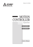
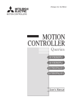
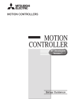
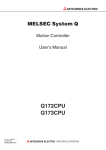
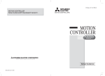
H1-Motion 2009
3/27/09
6:00 PM
Page 193
Motion Controller
QD Series for iQ Platform ................................................................................................................................................................194
QH Series ..........................................................................................................................................................................................202
QD75MH Type PLC Positioning Modules........................................................................................................................................210
MR-MQ100 Single Axis Module ......................................................................................................................................................213
Stock Product: Stock product is product MEAU makes every effort to have on hand for immediate shipment. There may be instances when we are out of stock due
to unexpected large requirements. All stock product will be indicated in this book by an “S” in the Stocked Item columns/rows.
Non-Stock Product: Non-stock product is product supplied on an “as-needed” basis. Standard lead times of 12 – 16 weeks apply, product is non-returnable and
non-cancelable. Product listed as non-stock may change to stock product subject to increases in sales and usage. All non-stock product will be indicated in this book by
a dash “–” in the Stocked Item columns/rows.
Mitsubishi Electric Automation
|
Motion Controllers 193
n MOTION CONTROLLERS
H1-Motion 2009
3/27/09
6:00 PM
Page 194
QD Series Motion Controllers for the iQ Platform
The performance of the Q172D/Q173D Motion CPUs is twice as fast as the previous generation systems resulting in
shorter system times. Shared memory capacity has been increased 3.5 times, Motion SFC processing time is reduced
by three-quarters, in-position signal response time has been decreased by half and programs read and write times have
been increased three times when compared with Q172H/Q173H motion CPU models.
B
C
G
A
E
F
F
F
A. CPU Base Unit / Power Supply Module / CPU Modules ..........................................................................195
B. Motion Controller CPU Modules ................................................................................................................195
C External Signal Interface Module ..............................................................................................................196
D. Synchronous Encoder and Interface Module ............................................................................................197
E. Manual Pulse Generator and Interface Module ........................................................................................198
F. Misc Parts/Cables/Connectors/Manuals....................................................................................................198
G. Operating/Programming Software ............................................................................................................201
194
D
H1-Motion 2009
3/27/09
6:00 PM
Page 195
A iQ Series Base Units
Model Number
Q38DB
Q312DB
Type
Q63B
Q65B
Base Unit
Q68B
Q612B
Q63P
Q64P
Extension Base Unit
Specifications and Extension
Connection Cables
See iQ section of this PSG for detailed information and specifications
Power Supply Modules
Model Number
Q61P-A1
Q61P-A2
Q61P
Q62P
See iQ section of this PSG for detailed information and specifications
Specifications
Sequence CPU Modules
Model Number
Q03UDCPU
Q04UDHCPU Q06UDHCPU Q13UDHCPU Q26UDHCPU
Q03UDECPU Q04UDEHCPU Q06UDEHCPU Q13UDEHCPU Q26UDEHCPU
See iQ section of this PSG for detailed information and specifications
Specifications
Cables for CPU to Extension Base Unit or Extension Base Unit to Extension Base Unit
QC100B
Q173DCPU
Q172DCPU
CD
AB E
2
1
SW
2
CAUTION
789
CAUTION
EMI
CN2
CN1
CN1
EMI
Motion Controller CPU Modules
F 01
STOP RUN
STOP RUN
B
45
23 6
F 01
SW
45
23 6
45
23 6
1
F 01
45
23 6
F 01
CD
AB E
QC50B
CDE
AB
QC30B
CDE
AB
QC12B
See iQ section of this PSG for detailed information and specifications
789
QC06B
789
QC05B
Specifications
789
Model Number
FRONT
BAT
Specifications
Model Number
Q173DCPU
Stocked Item
Q172DCPU
S
S
Up to 32 axes
Up to 8 axes
SV13
0.44ms / 1 to 6 axes
0.88m / 7 to 18 axes
1.77ms / 19 to 32 axes
0.44ms / 1 to 6 axes
0.88ms / 7 to 8 axes
SV22
0.44ms / 1 to 4 axes
0.88ms / 5 to 12 axes
1.77ms / 13 to 28 axes
3.55ms / 29 to 32 axes
0.44ms / 1 to 4 axes
0.88ms / 5 to 8 axes
Number of Control Axes
Operation Cycle
(Default)
Interpolation Functions
Control Modes
Acceleration/ Deceleration Control
Linear interpolation (Up to 4 axes), Circular interpolation (2 axes), Helical interpolation (3 axes)
PTP(Point to Point) control, Speed control, Speed-position control, Fixed-pitch feed, Constant speed control, Position follow-up control,
Speed control with fixed position stop, Speed switching control, High-speed oscillation control, Synchronous control (SV22)
Automatic trapezoidal acceleration/deceleration, S-curve acceleration/deceleration
Backlash compensation, Electronic gear, Phase compensation (SV22)
Compensation
Programming Language
Motion SFC, Dedicated instruction, Mechanical support language (SV22)
Servo Program Capacity
14k steps
Number of Positioning Points
3200 points (Positioning data can be designated indirectly)
Peripheral I/F
Home Position Return Function
Via PLC CPU (USB/RS-232)
Proximity dog type (2 types), Count type (3 types), Data set type (2 types), Dog cradle type, Stopper type (2 types),
Limit switch combined type (Home position return retry function provided, home position shift function provided)
JOG Operation Function
Provided
Manual Pulse Generator Operation
Function
Synchronous Encoder
Possible to connect 3 modules
Possible to connect 12 modules
Absolute Position System
Number of SSCNET III Systems (*1)
Motion Related Interface Module
Internal Current
Number of output points 32 points Watch data: Motion control data/Word device
Made compatible by setting battery to servo amplifier.
(Possible to select the absolute data method or incremental method for each axis)
2 systems
1 system
Q172DLX : 4 modules usable
Q172DEX : 6 modules usable
Q173DPX : 4 modules usable (*2)
Q172DLX : 1 module usable
Q172DEX : 4 modules usable
Q173DPX : 3 modules usable (*2)
1.14
Dimensions (W x D x H) mm (in)
Weight (kg)
Possible to connect 8 modules
M-code output function provided M-code completion wait function provided
M-Code Function
Limit Switch Output Function
FRONT
BAT
1.25
27.4 x 98 x 119.3 (1.08 x 3.86 x 4.70)
0.33
0.33
Notes:
1. The MR-J2S-B servo amplifiers for SSCNET cannot be used.
2. When using the incremental synchronous encoder (SV22 use), you can use above number of modules. When connecting the manual pulse generator, you can use only 1 module.
Mitsubishi Electric Automation
|
Motion Controllers 195
n MOTION CONTROLLERS
H1-Motion 2009
3/27/09
6:00 PM
Page 196
C External Signal Interface Module
Servo External Signal
Application
Number of Points
Q172DLX
Upper Stroke Limit Input (FLS)
For detection of upper and lower stroke limits
Lower Stroke Limit Input (RLS)
Stop Signal Input (STOP)
Proximity DOG/
Speed-Position Switching Input
(DOG/CHANGE)
For stopping under speed or positioning control
32 points
For detection of proximity DOG at proximity DOG or count
type home position return or for switching from speed to
position switching control.
(4 points/8 axes)
CTRL
Note: Signal No. 1 to 8 can be assigned to the specified axis. To make the assignment, use the system settings of the positioning software package.
Q172DLX
Q172DLX
S
Model Number
Stocked Item
Servo external signals: 32 points
(Upper stroke limit, Lower stroke limit, Stop input,
Proximity DOG/Speed-position switching signal)
(4 points x 8 axes)
Number of Inputs
Input Method
Sink/Source type
Isolation Method
Photocoupler
Rated Input Voltage
12/24 VDC
Rated Input Current
12 VDC 2mA/24 VDC 4mA
Operating Voltage Range
10.2 to 26.4 VDC (12/24 VDC +10/ -15%, ripple ratio 5% or less)
ON Voltage/Current
10 VDC or more/2.0mA or more
OFF Voltage/Current
1.8 VDC or less/0.18mA or less
Approx. 5.6KΩ
Input Resistance
Response time of the
Upper/Lower Stroke Limit
and STOP Signal
OFF to ON
Response Time of the
Proximity DOG, SpeedPosition Switching Signal
OFF to ON
ON to OFF
Common Terminal Arrangement
Indicates to Display
External Connector Type
Applicable Wire Size
Applicable Connector for the External
Connection
0.4ms/0.6ms/1ms
(CPU parameter setting, Default 0.4ms)
32 points/common (common terminal: B1, B2)
ON indication (LED)
40 pin connector
0.3mm 2
A6CON1 (Attachment),
A6CON2, A6CON3 (Optional)
Applicable Connector/
Terminal Block Converter Module
A6TBXY36, A6TBXY54, A6TBXY70 (Optional)
Number of I/O Occupying Points
32 points (I/O allocation: Intelligent, 32 points)
Internal Current Consumption (5VDC) [A]
Dimensions [mm (inch)] (W x H x D)
Weight (kg)
196
1ms
ON to OFF
0.06
27.4 x 98 x 90
(1.08 x 3.86 x 3.54)
0.15
H1-Motion 2009
3/27/09
6:00 PM
Page 197
D QD Series Serial Absolute Synchronous Encoder and Interface Module
Serial Absolute Synchronous Encoder I/F
Q172DEX
SY.ENC
1
2
TREN
1
2
Model Number
Q172DEX
Applicable Signal Types
SY.ENC1
M
SY.ENC2
Differential-output type : (SN75C1168 or equivalent)
Transmission Method
Serial communications
Synchronous Method
Counter-clock-wise (viewed from end of shaft)
Communication Speed
2.5 Mbps
Applicable Types
Q170ENC
Q172DEX
Tracking Enable Signal Input
Model Number
Stocked Item
Q172DEX
S
Number of Inputs
Input Method
Tracking enable signal: 2 points
Sink/Source type
Isolation Method
Photocoupler
Rated Input Voltage
12/24 VDC
Rated Input Current
12 VDC 2mA/24 VDC 4mA
Operating Voltage Range
10.2 to 26.4 VDC
(12/24 VDC +10 / -15%, ripple ratio 5% or less)
Position Detection Method
Absolute (ABS) method
Resolution
262144 PLS/rev (18bit)
Number of Modules
2/module
External Connector Type
Applicable Connector for the
External Connection
Applicable Wire
Recommended Cables
Up to 50m (164.04 ft.)
Back up the Absolute Position
10 VDC or more/2.0mA or more
1.8 VDC or less/0.18mA or less
Battery Service Life Time
(Value in Actual)
Approx. 5.6KΩ
Memory of Data Exchange
Response
Time
ON to OFF
Common Terminal
Arrangement
Display
0.4ms/0.6ms/1ms
(CPU parameter setting, Default 0.4ms)
1 point/common
(Common terminal: TREN.COM)
ON indication (LED)
n M n = cable length 2m (6.56 ft.), 5m (16.4 ft.),
Q170ENCCBLn
10m (32.81 ft.), 20m (65.62 ft.), 30m (98.43 ft.), 50m (164.04 ft.) (Note)
Cable Length
OFF Voltage/Current
OFF to ON
Q170ENCCNS (Optional)
MB14B0023 12 Pair
ON Voltage/Current
Input Resistance
20 pin connector
Depends on A6BAT/MR-BAT
12000 [h], (Example of encoders x 2, ambient temperature 40°C (104°F) )
24000 [h], (Example of encoders x 1, ambient temperature 40°C (104°F) )
Number of I/O Occupying Points
None
32 points (I/O allocation: Intelligent, 32 points)
Internal Current Consumption
(5VDC) [A]
Dimensions [mm (inch)]
0.19
98 x 27.4 x 90 (3.86 x 1.08 x 3.54) H x W x D
Weight [kg]
0.15
Note: Use these cables when the tracking enable signal is not used. Customer must make a cable when
the tracking enable signal is used.
QD Series Synchronous Encoder (optional)
Model Number
Q170ENC
Stocked Item
S
Resolution
Transmission Method
Direction on Increase
Protective
Construction (*1)
Permitted Speed at ON
Permitted Speed at OFF (*2)
Permitted Axis Load
Runout at Input Shaft Tip
262144 PLS/rev
Serial Communications (Connected to Q172EX-S2/S3)
Counter clockwise (viewed from end of shaft)
IP65 (dust proof, waterproof)
except for the shaft-through portion
3600 r/min
500 r/min
Radial load: Max 19.6N
Thrust load: Max 9.8N
0.02 mm (0.00079 in) or less
15 mm (0.59 in) from tip
Recommended Coupling
Permissible Angular
Acceleration
Internal Current Consumption
Connecting Cable
Communication Method
Bellows coupling
40,000 rad/s2
0.2 (A)
nM
Q170ENCCBLn
n = cable length 2m (6.56 ft.), 5m (16.4 ft.),
10m (32.8 ft.), 20m (65.6 ft.), 30m (98.4 ft.),
50m (164.04 ft.)]
Differential driver/receiver conforming to RS-422A
Transmission Distance
Up to 50 m (164.04 ft)
Operating Temperature
-5°C to 55°C (23 to 131°F)
Weight kg (lbs)
0.6 (1.3)
Notes:
1. If an “o-ring” is required, please purchase separately.
2. If it exceeds a permitted speed at power OFF, a position displacement is generated.
Mitsubishi Electric Automation
|
Motion Controllers 197
3/27/09
6:00 PM
Page 198
E QD Series Manual Pulse Generator and Interface Module
Q173DPX
PLS.A PLS.B TREN
1
1
1
2
2
2
3
3
3
Serial Absolute Synchronous Encoder I/F
Model Number
Q173DPX
Stocked Item
PULSER
S
Number of Modules (Max.)
Voltage-output/
Open collector
Q173DPX
Model Number
3 per CPU
High Voltage
3.0 to 5.25 VDC
Low Voltage
0 to 1.0 VDC
Differential-Output High Voltage
Type (26LS31 or
Low Voltage
Equivalent)
Tracking Enable Signal Input
Q173DPX
Stocked Item
2.0 to 5.25 VDC
0 to 0.8 VDC
Input Frequency
Max. 200kpps (After magnification by 4)
Applicable Types
Voltage-output type/Open-collector type (5 VDC),
Recommended product: MR-HDP01; Differential-output
type: (26LS31 or equivalent)
S
Tracking enable signal: 3 points
Number of Inputs
Input Method
Sink/Source type
Isolation Method
External Connector Type
Photocoupler
12/24 VDC
Rated Input Current
12 VDC 2mA/24 VDC 4mA
ON Voltage/Current
10 VDC or more / 2.0 mA or more
OFF Voltage/Current
1.8 VDC or less / 0.18 mA or less
Input Resistance
Approx. 5.6KΩ
Common Terminal
Arrangement
1 point/common
(Common terminal: TREN.COM)
Display
0.3mm 2
Applicable Connector for the
External Connection
10.2 to 26.4 VDC (12/24 VDC +10/ -15%,
ripple ratio 5% or less)
Operating Voltage
Range
40 pin connector
Applicable Wire Size
Rated Input Voltage
A6CON1 (Attachment) A6CON2, A6CON3 (Optional)
Applicable Connector/
Terminal Block Converter Module
Cable Length
A6TBXY36, A6TBXY54, A6TBXY70 (Optional)
Voltage-Output/Open
Collector Output Type
Differential-Output Type
30m (98.43 ft.)
(Open collector output type: 10m (32.81 ft.) )
Number of I/O Occupying Points
32 points (I/O allocation: Intelligent, 32 points)
Internal Current Consumption
0.38
Dimensions mm (inch)
ON indication (LED)
98 x 27.4 x 90 (3.86 x 1.08 x 3.54) H x W x D
Weight (kg)
0.15
QD Series Manual Pulse Generator (optional)
Pulse Generator
ManualManual
pulse generator
MR-HDP01
unit : mm (inch)
Model Number
70
30
80
ø70 (2.76)
ø50 (1.97)
NP
90
+
+
50
40
(2.44 ±
) 02
.83) ±0.2
+
+
27.0 ±0.5
16 20
(0.63)(0.79) (1.06)
S
25 PLS/rev (100 PLS/rev at magnification of 4)
Voltage - output (power supply voltage - 1V or
more), Output current = Up to 20 mA
Power Supply Voltage
+
+ + + +
8.89
(0.35)
Pulse Resolution
Output Method
+
+5 to
12V0V A B
4.5 to 13.2 VDC
Consumption Current
7.6
(0.3)
Unit: mm (inch)
ø62
ø72 (2
3 X studs(M4 X 10)
PCD72 equi-spaced
M3 X 6
3-ø4.8 (0 to 19)
Equi-spaced
+
ø60 (2.36)±0.5
ø80 (3.15)±1
0
20
10
MR-HDP01
Stocked Item
3.6 (0.14) Packing t = 2.0
60
KSD06S
1 2 3 4 5 6
ON
n MOTION CONTROLLERS
H1-Motion 2009
Life
60
1,000,000 revolutions at 200 r/min
Permitted Axis Load
Radial load : Max. 19.6N
Thrust load : Max. 9.8N
Pulse Signal Status
2 signals: A phase, B: phase, 90° phase difference
0.1N/m (at 20°C (68°F))
Friction Torque
+
Operating Temperature
-10°C to +60°C (14°F to 140°F)
Weight kg (lbs)
Note: If using an external power supply, it needs to be 5 VDC.
198
0.4 (0.88)
H1-Motion 2009
3/27/09
6:00 PM
Page 199
QD Misc. Parts • Cables • Connectors • Manuals
F
Connection between Q173DCPU and
MR-J3-B Series Servo Amplifiers
Connection between Q172DCPU and MRJ3-B Series Servo Amplifiers
Q173DCPU Motion CPU module
Q172DCPU Motion CPU module
SSCNET cable length
MR-J3BUS M use
1) 3m(9.84ft.)
MR-J3BUS M-A use
1) 20m(65.62ft.)
MR-J3BUS M-B use
1) 50m(164.04ft.)
CN1
SSCNET cable length
MR-J3BUS M use
1) 3m(9.84ft.)
MR-J3BUS M-A use
1) 20m(65.62ft.)
MR-J3BUS M-B use
1) 50m(164.04ft.)
CN1
CN2
Cap
Attach a cap to
connectors of system
not being used.
SSCNET
MR-J3-B
SYSTEM1
MR-J3-B
MR-J3-B
MR-J3-B
CN1A
CN1A
1)
CN1B
Servo amplifier
Cap
CN1B
CN1B
Cap
CN1B
CN1A
1)
CN1A
Servo amplifier
Servo amplifier
Servo amplifier
SSCNET
SYSTEM2
MR-J3-B
MR-J3-B
CN1A
CN1A
Cap
CN1B
CN1B
Servo amplifier
Servo amplifier
Miscellaneous Parts
Model Number
Description
HMI
Please select the HMI from the GOT1000 series in this Product Selection Guide
Stocked Item
Q170DBATC
Battery holder for Q6BAT (Battery Not Included)
S
Q6BAT
Battery for memory data backup of SRAM built-in Motion CPU
S
A6BAT
Battery for data backup of the Q170ENC
S
Q170DBATCBL05M
Cable between Q170DBATC holder and Motion CPU (0.5 Meters)
S
MR-J3USBCBL3M
USB cable from PC to PLC CPU
S
SC09
RS232 cable from PC to PLC CPU
S
N/A
Cables for Q172DCPU/Q173DCPU to MR-J3-B Servo Amplifiers
Model Number
Description
MR-J3BUS015M
0.15 meter SSCNET III (plastic) cable from Q172D/173DCPU to MR-J3-B Amplifier
Stocked Item
S
MR-J3BUS03M
0.3 meter SSCNET III (plastic) cable from Q172D/173DCPU to MR-J3-B Amplifier
S
MR-J3BUS05M
0.5 meter SSCNET III (plastic) cable from Q172D/173DCPU to MR-J3-B Amplifier
S
MR-J3BUS1M
1 meter SSCNET III (plastic) cable from Q172D/173DCPU to MR-J3-B Amplifier
S
MR-J3BUS3M
3 meter SSCNET III (plastic) cable from Q172D/173DCPU to MR-J3-B Amplifier
S
MR-J3BUS5M-A
5 meter SSCNET III (plastic) cable from Q172D/173DCPU to MR-J3-B Amplifier
S
MR-J3BUS10M-A
10 meter SSCNET III (plastic) cable from Q172D/173DCPU to MR-J3-B Amplifier
S
MR-J3BUS20M-A
20 meter SSCNET III (plastic) cable from Q172D/173DCPU to MR-J3-B Amplifier
S
MR-J3BUS30M-B
30 meter SSCNET III (glass) cable from Q172D/173DCPU to MR-J3-B Amplifier
S
MR-J3BUS40M-B
40 meter SSCNET III (glass) cable from Q172D/173DCPU to MR-J3-B Amplifier
—
MR-J3BUS50M-B
50 meter SSCNET III (glass) cable from Q172D/173DCPU to MR-J3-B Amplifier
—
Mitsubishi Electric Automation
|
Motion Controllers 199
n MOTION CONTROLLERS
H1-Motion 2009
3/27/09
6:00 PM
Page 200
Cables and Connectors for Special Function Modules
Model Number
Description
A6CON1
Q173DPX connector to use the manual pulse generator and incremental synchronous encoder or
Q172DLX connector to use the servo external input signals.
S
QD75MCBL-2M
2 meter I/O pigtail cable to use in place of the A6CON1 connector.
S
QD75MCBL-5M
5 meter I/O pigtail cable to use in place of the A6CON1 connector.
S
QD75MCBL-10M
10 meter I/O pigtail cable to use in place of the A6CON1 connector.
S
A6TBXY36
Q172DLX Terminal Block Conversion Module - Sink Type I/O (Standard Type)
S
A6TBXY54
Q172DLX Terminal Block Conversion Module - Sink Type I/O (2-Wire Type)
—
A6TBX70
Q172DLX Terminal Block Conversion Module - Sink Type I/O (3-Wire Type)
—
AC05TB
AC10TB
AC20TB
AC30TB
AC50TB
AC80TB
n n n Terminal Block Conversion Module
0.5 Meter cable from Q172DLX to A6TBXn
1 Meter cable from Q172DLX to A6TBXn
n n n Terminal Block Conversion Module
2 Meter cable from Q172DLX to A6TBXn
n n n Terminal Block Conversion Module
n n n Terminal Block Conversion Module
3 Meter cable from Q172DLX to A6TBXn
5 Meter cable from Q172DLX to A6TBXn
n n n Terminal Block Conversion Module
8 Meter cable from Q172DLX to A6TBXn
n n n Terminal Block Conversion Module
Stocked Item
S
S
S
S
S
—
AC100TB
n n n Terminal Block Conversion Module
10 Meter cable from Q172DLX to A6TBXn
Q170ENCCNS
Connector set for the Q170ENC absolute synchronous encoder
—
Q170ENCCBL2M
2 meter cable from the Q172DEX to the Q170ENC absolute synchronous encoder
S
Q170ENCCBL5M
5 meter cable from the Q172DEX to the Q170ENC absolute synchronous encoder
S
Q170ENCCBL10M
10 meter cable from the Q172DEX to the Q170ENC absolute synchronous encoder
S
Q170ENCCBL20M
20 meter cable from the Q172DEX to the Q170ENC absolute synchronous encoder
—
Q170ENCCBL30M
30 meter cable from the Q172DEX to the Q170ENC absolute synchronous encoder
—
Q170ENCCBL50M
50 meter cable from the Q172DEX to the Q170ENC absolute synchronous encoder
—
—
Cables for Forced Stop Input Connector (EMI)
Model Number
Description
Stocked Item
Q170DEMICBL05M
0.5 Meter cable for EMI connector on CPU
S
Q170DEMICBL1M
1 Meter cable for EMI connector on CPU
S
Q170DEMICBL3M
3 Meter cable for EMI connector on CPU
S
Q170DEMICBL5M
5 Meter cable for EMI connector on CPU
S
Q170DEMICBL10M
10 Meter cable for EMI connector on CPU
S
Q170DEMICBL15M
15 Meter cable for EMI connector on CPU
S
Q170DEMICBL20M
20 Meter cable for EMI connector on CPU
S
Q170DEMICBL25M
25 Meter cable for EMI connector on CPU
S
Q170DEMICBL30M
30 Meter cable for EMI connector on CPU
S
Manuals
200
Model Number
Description
IB(NA)0300133
Q173DCPU/Q172DCPU User's Manual
Stocked Item
Meau.com
IB(NA)0300134
Q173DCPU/Q172DCPU Programming Manual (Common)
Meau.com
IB(NA)0300135
Q173DCPU/Q172DCPU Programming Manual (Motion SFC)
Meau.com
IB(NA)0300136
Q173DCPU/Q172DCPU Programming Manual (Real Mode)
Meau.com
IB(NA)0300137
Q173DCPU/Q172DCPU Programming Manual (Virtual Mode)
Meau.com
SH(NA)030051
MR-J3-B servo amplifier instruction manual
Meau.com
SH(NA)030041
MR-J3 servo motor instruction manual
Meau.com
H1-Motion 2009
G
3/27/09
6:00 PM
Page 201
Operating / Programming Software
MT Developer Software
Conveyor assembly use
Automatic machinery use
Motion SFC compatible
Dedicated language
Motion SFC compatible
SW8DNC-SV13QB (Q173DCPU)
SW8DNC-SV13QD (Q172DCPU)
Mechanical support language
SW8DNC-SV22QA (Q173DCPU)
SW8DNC-SV22QC (Q172DCPU)
Electronic component assembly,
Inserter, Feeder, Molder, Conveying
equipment, Paint applicator, Chip
mounting, Wafer slicer, Loader/Unloader,
Bonding machine, X-Y table
Press feeder, Food processing, Food
packaging, Winding machine, Spinning
machine, Textile machine, Printing
machine, Book binder, Tire molder,
Paper-making machine
Linear interpolation (1 to 4 axes), Circular interpolation,
Constant-speed, Fixed-pitch feed, Speed control with
fixed position stop, Speed switching, Speed control,
Speed/position switching
Synchronous control, Electronic shaft,
Electronic clutch, Electronic cam, Draw
control
Q Series Integrated Start-up Support Software Packages
Model Number
Stocked Item Description
SW1DNC-MTW2-E
(Integrated start-up support software)
MT-DEV2-C1
S
Details
Conveyor assembly software
Automatic machinery software
Cam data creation software
Digital oscilloscope software
Document print software
Help section
QD Series Q172DCPU (SSCNET III)
Operating Software (OS)
SW8DNC-SV13QD: For conveyor assembly
QD Series Q173DCPU (SSCNET III)
Operating Software (OS)
SW8DNC-SV13QB: For conveyor assembly
SW8DNC-SV22QC: For automatic machinery
SW8DNC-SV22QA: For automatic machinery
Single user license – can be used on 1 computer at a time; Installation manual included
MT-DEV2-C5
–
5 user license – can be used on up to 5 computers at a time
MT-DEV2-C10
–
10 user license – can be used on up to 10 computers at a time
MT-DEV2-C25
–
25 user license – can be used on up to 25 computers at a time
MT-DEV2-C50
–
50 user license – can be used on up to 50 computers at a time
Mitsubishi Electric Automation
|
Motion Controllers 201
n MOTION CONTROLLERS
H1-Motion 2009
3/27/09
6:00 PM
Page 202
QH Series Motion Controllers
The QH Series Motion Controllers meet your needs for higher performance and smaller size. Ideal for 1.5 axes to 96 control
axes. Various motion controller operating system software packages are also available. With increased high-speed motion,
flexibility and compatibility of the Q Series Automation Platform, the QH Series Motion Controllers are the best choice for
next-generation motion control technology!
B
C
A
H
G
E
D
F
Q Series
F
QH Series
A. CPU Base Units / Power Supply Module / CPU Modules ........................................................................................................203
B. Motion Controller CPU Modules................................................................................................................................................203
C. Special Function Modules ........................................................................................................................................................204
D. Synchronous Encoder ..............................................................................................................................................................205
E. Manual Pulse Generator ..........................................................................................................................................................206
F. Peripheral Equipment ................................................................................................................................................................206
G. Misc. Parts / Cables / Connectors/Manuals ..............................................................................................................................207
H. Operating / Programming Software ..........................................................................................................................................209
202
H1-Motion 2009
A
3/27/09
6:00 PM
Page 203
Q Series CPU Base Units
iQ Series Base Information
Model Number
Q38B-E
Type
Q35B-E
Q38B-E
Q312B-E
Q63B
Q65B
Base Unit
Specifications and Extension
Connection Cables
Q68B
Q612B
Extension Base Unit
See Q section of this PSG for detailed information and specifications
Power Supply Modules
Model Number
Q61P-A1
Q61P-A2
Specifications
Q62P
Q63P
Q64P
See Q section of this PSG for detailed information and specifications
Sequence CPU Modules
Model Number
Q00CPU
Q01CPU
Q02CPU
Q02HCPU
Q06HCPU
Q12HCPU
Q25HCPU
See Q section of this PSG for detailed information and specifications
Specifications
Cables for CPU to Extension Base Unit or Extension Base Unit to Extension Base Unit
Model Number
QC05B
QC06B
QC12B
QC30B
QC50B
QC100B
See Q section of this PSG for detailed information and specifications
Specifications
B QH Series Motion Controller CPU Modules
Model Number
Q172HCPU (SSCNET III)
Stocked Item
Q173HCPU (SSCNET III)
S
S
8 axes
32 axes
SV13
0.44ms / 1 to 3 axes
0.88ms / 4 to 8 axes
0.44ms / 1 to 3 axes
0.88ms / 4 to 10 axes
1.77ms / 11 to 20 axes
3.55ms / 21 to 32 axes
SV22
0.88ms / 1 to 4 axes
1.77ms / 5 to 8 axes
0.88ms / 1 to 5 axes
1.77ms / 6 to 14 axes
3.55ms / 15 to 28 axes
7.11ms / 29 to 32 axes
Number of Control Axes
Operation Cycle
(Default)
Interpolation Functions
Control Modes
Acceleration/ Deceleration Control
Compensation
Programming Language
Linear interpolation (4 axes max.), circular interpolation (2 axes), Helical interpolation (3 axes)
PTP (Point to Point) control, Speed control, Speed-position control, Fixed-pitch feed, Constant speed control,
Position follow-up control, Speed switching control, High-speed oscillation control, Synchronous control (SV22)
Automatic trapezoidal acceleration/deceleration, S-curve acceleration/deceleration
Backlash compensation, electronic gear, phase compensation (SV22)
Motion SFC, dedicated instruction, mechanical support language (SV22)
Program Capacity
14k steps
Number of Positioning Points
3200 points (Positioning data can be designated indirectly)
Programming Tool
IBM PC/AT
Peripheral I/F
Home Position Return Function
USB / SSCNET III
Proximity DOG type (2 types), Count type (3 types), Data set type (2 types)
DOG cradle type, Stopper type (2 types), Limit switch combined type (Home position return re-try function provided, home position
shift function provided)
JOG Operation Function
Provided
Manual Pulse Generator Operation
Function
Synchronous Encoder
M-Code Function
Limit Switch Output Function
Absolute Position System
Number of SSCNET II I/F
Number of SSCNET III Systems
Manual Pulse Generator/
Synchronous Encoder/ Servo External
Signals Interface Module
Internal Current
Possible to connect 3 modules
Possible to connect 12 modules
Number of output points 32 point/axis. Watch data: Motion control data/Word device
Made compatible by setting battery to servo amplifier. (Possible to select the absolute data method or incremental method for each axis)
—
—
1 systems
2 system
Q172LX: 1 module usable
Q172EX: 4 modules usable
Q173PX: 3 modules usable (*1)
Q172LX: 4 modules usable
Q172EX: 6 modules usable
Q173PX: 4 modules usable (*1)
1.14
1.25
Dimensions (W x H x D) mm (inch)
Weight (kg)
Possible to connect 8 modules
M-code output function provided M-code completion wait function provided
27.4 x 104.6 x 114.3 (1.08 x 4.12 x 4.50)
0.22
0.23
Note:
1. When using the incremental synchronous encoder by using SV22, you can use 4 modules. When connecting the manual pulse generator, you can use only one module.
Mitsubishi Electric Automation
|
Motion Controllers 203
n MOTION CONTROLLERS
H1-Motion 2009
3/27/09
C
6:00 PM
Page 204
Special Function Modules
QH Series Servo External Signals Interface Module
The Q172LX is assigned a set of input numbers per axis. The system setting of the
positioning software package is used to determine the I/O numbers corresponding
to the axis numbers.
Servo External Signal
Application
Number of Points
Upper Stroke Limit Input (FLS)
For detection of upper and lower stroke limits
Lower Stroke Limit Input (RLS)
Stop Signal Input (STOP)
Proximity DOG/
Speed-Position Switching Input
(DOG/CHANGE)
For stopping under speed or positioning control
32 points
For detection of proximity DOG at proximity DOG or count
type home position return or for switching from speed to
position switching control.
(4 points/8 axes)
Note: Signal No. 1 to 8 can be assigned to the specified axis. To make the assignment, use the system settings of the positioning software package.
Model Number
Stocked Item
Q172LX
S
Servo external signals: 32 points
(Upper stroke limit, Lower stroke limit, Stop input,
Proximity DOG/Speed-position switching signal)
(4 points x 8 axes)
Number of Inputs
Input Method
Sink/Source type
Isolation Method
Photocoupler
Rated Input Voltage
12/24 VDC
Rated Input Current
12 VDC 2mA/24 VDC 4mA
Operating Voltage Range
10.2 to 26.4 VDC (12/24 VDC +10/ -15%, ripple ratio 5% or less)
ON Voltage/Current
Min.10 VDC or more/2.0mA or more
OFF Voltage/Current
Max.1.8 VDC or less/0.18mA or less
Input Resistance
Approx. 5.6KΩ
Response time of the
Upper/Lower Stroke Limit
and STOP Signal
OFF to ON
Response Time of the
Proximity DOG, SpeedPosition Switching Signal
OFF to ON
ON to OFF
Common Terminal Arrangement
Indicates to Display
External Connector Type
Applicable Wire Size
Applicable Connector for the External
Connection
0.4ms/0.6ms/1ms
(CPU parameter setting, Default 0.4ms)
32 points/common (common terminal: B1, B2)
ON indication (LED)
40 pin connector
0.3mm 2
A6CON1 (Attachment),
A6CON2, A6CON3 (Optional)
Applicable Connector/
Terminal Block Converter Module
A6TBXY36, A6TBXY54, A6TBXY70 (Optional)
Number of I/O Occupying Points
32 points (I/O allocation: Intelligent, 32 points)
Internal Current Consumption (5VDC) [A]
Dimensions [mm (inch)] (W x H x D)
Weight (kg)
204
1ms
ON to OFF
0.05
27.4 x 98 x 89.3 (1.08 x 3.86 x 3.52)
0.15
H1-Motion 2009
3/27/09
6:00 PM
Page 205
D QH Series Serial Absolute Synchronous Encoder and Interface Module
Serial Absolute Synchronous Encoder I/F
Tracking Enable Signal Input
Model Number
Stocked Item
Number of Inputs
Input Method
172EX-S2
Q172EX-S3
S
–
Tracking enable signal: 2 points
Sink/Source type
Isolation Method
Photocoupler
Rated Input Voltage
12/24 VDC
Rated Input Current
12 VDC 2mA/24 VDC 4mA
Operating Voltage Range
10.2 to 26.4 VDC
(12/24 VDC +10 / -15%, ripple ratio 5% or less)
Model Number
Q172EX-S2
Applicable Signal Types
Differential-output type : (SN75C1168 or equivalent)
Q172EX-S3
Transmission Method
Serial communications
Synchronous Method
Counter-clock-wise (viewed from end of shaft)
Communication Speed
2.5 Mbps
Applicable Types
Q170ENC
Position Detection Method
Absolute (ABS) method
Resolution
262144 PLS/rev (18bit)
Number of Modules
2/module
External Connector Type
20 pin connector
Applicable Connector for the
External Connection
Q170ENCCNS (Optional)
Applicable Wire
MB14B0023 12 Pair
Q170ENCCBLn
n M n = cable length 2m (6.56 ft.), 5m (16.4 ft.),
10m (32.81 ft.), 20m (65.62 ft.), 30m (98.43 ft.), 50m (164.04 ft.)] (Note)
Recommended Cables
Cable Length
Up to 50m (164.04 ft.)
Back up the Absolute Position
Depends on A6BAT/MR-BAT
12000 [h], (Example of encoders x 2, ambient temperature 40°C (104°F) )
24000 [h], (Example of encoders x 1, ambient temperature 40°C (104°F) )
ON Voltage/Current
10 VDC or more/2.0mA or more
OFF Voltage/Current
1.8 VDC or less/0.18mA or less
Battery Service Life Time
(Value in Actual)
Approx. 5.6KΩ
Memory of Data Exchange
None
Number of I/O Occupying Points
32 points (I/O allocation: Intelligent, 32 points)
Input Resistance
Response
Time
OFF to ON
ON to OFF
Common Terminal
Arrangement
Display
0.4ms/0.6ms/1ms
(CPU parameter setting, Default 0.4ms)
1 point/common
(Common terminal: TREN.COM)
ON indication (LED)
Provided
Internal Current Consumption
(5VDC) [A]
Dimensions [mm (inch)]
0.19
98 x 27.4 x 90 (3.86 x 1.08 x 3.54) H x W x D
Weight [kg]
0.15
Note: Use these cables when the tracking enable signal is not used. Customer must make a cable when the tracking enable signal is used.
QH Series Synchronous Encoder (optional)
Q170ENC
IModel Number
Stocked Item
S
Resolution
Transmission Method
Direction on Increase
Protective
Construction (*1)
Permitted Speed at ON
Permitted Speed at OFF (*2)
Permitted Axis Load
Runout at Input Shaft Tip
262144 PLS/rev
Serial Communications (Connected to Q172EX-S2/S3)
Counter clockwise (viewed from end of shaft)
IP65 (dust proof, waterproof)
except for the shaft-through portion
3600 r/min
500 r/min
Radial load: Max 19.6N
Thrust load: Max 9.8N
0.02 mm (0.00079 in) or less
15 mm (0.59 in) from tip
Recommended Coupling
Permissible Angular
Acceleration
Internal Current Consumption
Connecting Cable
Communication Method
Bellows coupling
40,000 rad/s2
0.2 (A)
nM
Q170ENCCBLn
n = cable length 2m (6.56 ft.), 5m (16.4 ft.),
10m (32.8 ft.), 20m (65.6 ft.), 30m (98.4 ft.),
50m (164.04 ft.)]
Differential driver/receiver conforming to RS-422A
Transmission Distance
Up to 50 m (164.04 ft)
Operating Temperature
-5°C to 55°C (23 to 131°F)
Weight kg (lbs)
0.6 (1.3)
Notes:
1. If an “o-ring” is required, please purchase separately.
2. If it exceeds a permitted speed at power OFF, a position displacement is generated.
Mitsubishi Electric Automation
|
Motion Controllers 205
n MOTION CONTROLLERS
H1-Motion 2009
3/27/09
6:00 PM
Page 206
E QH Series Manual Pulse Generator and Interface Module
Manual Pulse Generator I/F
Model Number
Q173PX-S1
Stocked Item
S
Number of Modules (Max.)
Voltage-output/
Open collector
Q173PX-S1
Stocked Item
Tracking enable signal: 3 points
Input Method
Sink/Source type
Isolation Method
12/24 VDC
Rated Input Current
12 VDC 2mA/24 VDC 4mA
Operating Voltage
Range
10.2 to 26.4 VDC (12/24 VDC +10/ -15%,
ripple ratio 5% or less)
ON Voltage/Current
10 VDC or more / 2.0 mA or more
OFF Voltage/Current
1.8 VDC or less / 0.18 mA or less
Input Resistance
Approx. 5.6KΩ
Display
NP
ø70 (2.76)
ø50 (1.97)
80
70
ø60 (2.36)±0.5
ø80 (3.15)±1
90
20
Voltage-output type/Open-collector type (5 VDC),
Recommended product: MR-HDP01; Differential-output
type: (26LS31 or equivalent)
60
A6CON1 (Attachment) A6CON2, A6CON3 (Optional)
A6TBXY36, A6TBXY54, A6TBXY70 (Optional)
30m (98.43 ft.)
(Open collector output type: 10m (32.81 ft.) )
Provided
32 points (I/O allocation: Intelligent, 32 points)
0.38
98 x 27.4 x 90 (3.86 x 1.08 x 3.54)
0.15
QH Series Manual Pulse Generator (optional)
Model Number
MR-HDP01
Stocked Item
S
3 X studs(M4 X 10)
PCD72 equi-spaced
25 PLS/rev (100 PLS/rev at magnification of 4)
Voltage - output (power supply voltage - 1V or more),
Output current = Up to 20 mA
Pulse Resolution Method
+
+
+5 to
12V0V A B
Power Supply Voltage
8.89
(0.35)
4.5 to 13.2 VDC
+
+ + + +
Consumption Current
7.6
(0.3)
60
Life
1,000,000 revolutions at 200 r/min
Permitted Axis Load
Radial load : Max. 19.6N; Thrust load : Max. 9.8N
Pulse Signal Status
2 signals: A phase, B: phase, 90° phase difference
50
40
(2.44
) ±02
27.0 ±0.5
16 20
(0.63)(0.79) (1.06)
0.3mm 2
unit : mm (inch)
M3 X 6
3-ø4.8 (0 to 19)
Equi-spaced
40 pin connector
Applicable Wire Size
Applicable Connector for the
External Connection
Applicable Connector/
Terminal Block Converter Module
Voltage-Output/Open
Collector Output Type
Cable Length
Differential-Output Type
Memory for Data Exchange
Weight [kg]
3.6 (0.14) Packing t = 2.0
30
Applicable Types
Dimensions [mm (inch)] H x W x D
Pulse Generator
ManualManual
pulse generator
MR-HDP01
+
Max. 200kpps (After magnification by 4)
Internal Current Consumption
ON indication (LED)
+
0 to 0.8 VDC
Input Frequency
Number of I/O Occupying Points
1 point/common
(Common terminal: TREN.COM)
Common Terminal
Arrangement
+
0 to 1.0 VDC
2.0 to 5.25 VDC
External Connector Type
Photocoupler
Rated Input Voltage
0
3.0 to 5.25 VDC
Low Voltage
S
Number of Inputs
10
High Voltage
Differential-output High Voltage
type (26LS31 or
Low Voltage
equivalent)
Tracking Enable Signal Input
Model Number
3 per CPU
.83) ±0.2
Unit: mm (inch)
ø62
ø72 (2
Operating Temperature
+
+
0.1N/m (at 20°C (68°F))
Friction Torque
-10°C to +60°C (14°F to 140°F)
Weight kg (lbs)
0.4 (0.88)
Note: If using an external power supply, it needs to be 5 VDC.
F
Peripheral Equipment
Operating Environment
Item
WindowsNT® 4.0
(Service Pack 2 or later)
or Windows® 98
CPU
Recommended Pentium®
133MHz or more
Memory Capacity
Hard Disk Free Space
Display
Application Software
Recommended
32MB or more
Windows® 2000
Windows® XP
Recommended
Recommended Pentium®II
Pentium® II 233MHz
450MHz or more
or more
Recommended
64MB or more
Recommended
192MB or more
SW6RNC-GSVE: 333MB + SW6RNC-GSVHELPE: 155 MB
(Possible to select installation)
SVGA (resolution 800 x 600 pixels, 256 colors) or more
Word 97, Excel 97 or Word 2000, Excel 2000 (For document printing)
Visual C++ 4.0 or more, Visual Basic 4.03 (32 bit) or more
(For communication API function)
Note:
WindowsNT®, Windows®, Word, Excel, Visual C++ and Visual Basic are either registered trademarks or trademarks of Microsoft
Corporation in the United States and/or other countries. Pentium® is a trademark or registered trademark of Intel Corporation or its
subsidiaries in the United States and/or other countries.
206
H1-Motion 2009
3/27/09
6:00 PM
Page 207
Peripheral Equipment
Model Number
Description
A10BD-PCF
SSC I/F PCI slot board for PC
Stocked Item
–
A30CD-PCF (Note)
SSC I/F PCMCIA card for laptop
S
HMI
Please select the HMI from the GOT1000/ E Series Human Machine Interfaces section in this Product Selection Guide
N/A
Note:
I/F card only – See Programming Software section model number MT-DEV-SET oo for the complete I/F Kit. (Software, PCMCIA, Cable). When using the A30CD-PCF, the PC card driver for
WindowsNT® provided by the personal computer manufacturer must be used.
G
QH Misc Parts • Cables • Connectors • Manuals
QH Series • Q172HCPU
QH Series • Q173HCPU
Connection between Q172HCPU and MR-J3-B servo amplifiers
Connection between Q173HCPU and MR-J3-B servo amplifiers
Miscellaneous Parts for the System
Model Number
Description
MR-BAT or A6BAT
Battery to be used with the Q173DV, Q170BAT or Q170ENC
Stocked Item
S
Q6BAT
Battery for IC-RAM memory backup of the Q173HCPU/Q172HCPU module.
S
Q170HBATC
Battery holder for Q6BAT (Battery is not supplied, order Q6BAT separately)
S
Cables for Q172H/173HCPU (SSCNET III) to MR-J3-B Servo Amplifiers
Model Number
Description
MR-J3BUS015M
0.15 meter SSCNET III (plastic) cable from Q172H/173HCPU to MR-J3-B Amplifier
Stocked Item
S
MR-J3BUS03M
0.3 meter SSCNET III (plastic) cable from Q172H/173HCPU to MR-J3-B Amplifier
S
MR-J3BUS05M
0.5 meter SSCNET III (plastic) cable from Q172H/173HCPU to MR-J3-B Amplifier
S
MR-J3BUS1M
1 meter SSCNET III (plastic) cable from Q172H/173HCPU to MR-J3-B Amplifier
S
MR-J3BUS3M
3 meter SSCNET III (plastic) cable from Q172H/173HCPU to MR-J3-B Amplifier
S
MR-J3BUS5M-A
5 meter SSCNET III (plastic) cable from Q172H/173HCPU to MR-J3-B Amplifier
S
MR-J3BUS10M-A
10 meter SSCNET III (plastic) cable from Q172H/173HCPU to MR-J3-B Amplifier
S
MR-J3BUS20M-A
20 meter SSCNET III (plastic) cable from Q172H/173HCPU to MR-J3-B Amplifier
S
MR-J3BUS30M-B
30 meter SSCNET III (glass) cable from Q172/H173HCPU to MR-J3-B Amplifier
S
MR-J3BUS40M-B
40 meter SSCNET III (glass) cable from Q172H/173HCPU to MR-J3-B Amplifier
–
MR-J3BUS50M-B
50 meter SSCNET III (glass) cable from Q172H/173HCPU to MR-J3-B Amplifier
–
Mitsubishi Electric Automation
|
Motion Controllers 207
n MOTION CONTROLLERS
H1-Motion 2009
3/27/09
6:00 PM
Page 208
Connectors for Servo Amplifiers
Model Number
Description
Connector Cap
Comes with 2 caps on the MR-J3-B amplifiers standard
Stocked Item
–
Cables, Connectors and Parts for Special Function Modules
Stocked Item
Model Number
Description
A6CON1
Q173PX connector to use the manual pulse generator and incremental synchronous encoder or Q172LX
connector to use the servo external input signals.
S
QD75MCBL-2M
2 meter I/O pigtail cable to use in place of the A6CON1 connector.
S
QD75MCBL-5M
5 meter I/O pigtail cable to use in place of the A6CON1 connector.
S
QD75MCBL-10M
10 meter I/O pigtail cable to use in place of the A6CON1 connector.
S
A6TBXY36
Q172LX Terminal Block Conversion Module - Sink Type Input/Output (Standard Type)
S
A6TBXY54
Q172LX Terminal Block Conversion Module - Sink Type Input/Output (2-wire Type)
–
AC05TB
0.5 meter cable from Q172LX to A6TBXYoo Terminal Block Conversion Module
S
AC10TB
1 meter cable from Q172LX to A6TBXYoo Terminal Block Conversion Module
S
AC20TB
2 meter cable from Q172LX to A6TBXYoo Terminal Block Conversion Module
S
AC30TB
3 meter cable from Q172LX to A6TBXYoo Terminal Block Conversion Module
S
AC50TB
5 meter cable from Q172LX to A6TBXYoo Terminal Block Conversion Module
S
AC80TB
8 meter cable from Q172LX to A6TBXYoo Terminal Block Conversion Module
–
AC100TB
10 meter cable from Q172LX to A6TBXYoo Terminal Block Conversion Module
–
Q170ENCCNS
Connector set for the Q170ENC absolute synchronous encoder
–
Q170ENCCBL2M
2 meter cable from the Q172EX-S2/S3 to the Q170ENC absolute synchronous encoder
–
Q170ENCCBL5M
5 meter cable from the Q172EX-S2/S3 to the Q170ENC absolute synchronous encoder
–
Q170ENCCBL10M
10 meter cable from the Q172EX-S2/S3 to the Q170ENC absolute synchronous encoder
–
Q170ENCCBL20M
20 meter cable from the Q172EX-S2/S3 to the Q170ENC absolute synchronous encoder
–
Q170ENCCBL30M
30 meter cable from the Q172EX-S2/S3 to the Q170ENC absolute synchronous encoder
–
Q170ENCCBL50M
50 meter cable from the Q172EX-S2/S3 to the Q170ENC absolute synchronous encoder
–
Cables for Peripheral Equipment
Model Number
Q170BDCBL3M
Q170BDCBL5M
Q170BDCBL10M
Q170CDCBL3M (Note)
Q170CDCBL5M (Note)
Q170CDCBL10M (Note)
Description
3 meter cable for SSC I/F PCI slot board for PC
5 meter cable for SSC I/F PCI slot board for PC
10 meter cable for SSC I/F PCI slot board for PC
3 meter cable for SSC I/F PCMCIA card for laptop
5 meter cable for SSC I/F PCMCIA card for laptop
10 meter cable for SSC I/F PCMCIA card for laptop
Stocked Item
–
–
–
S
–
–
Note: I/F cable only – see programming software section model number MT-DEV-SET-C_ for the complete I/F kit. (software, PCMCIA card and cable)
Manuals
Model Number
IB(NA)0300110
IB(NA)0300111
IB(NA)0300112
IB(NA)0300113
IB(NA)0300114
SH(NA)030051
SH(NA)030041
208
Description
Q172HCPU/Q173HCPU motion controller user's manual
Q172HCPU/Q173HCPU motion controller programming manual (Common)
Q172HCPU/Q173HCPU motion controller (SV13/SV22) programming manual (SFC)
Q172HCPU/Q173HCPU motion controller (SV13/SV22) programming manual (REAL)
Q172HCPU/Q173HCPU motion controller (SV22) programming manual (VIRTUAL)
MR-J3-B servo amplifier instruction manual
MR-J3 servo motor instruction manual
Stocked Item
–
–
–
–
–
S
S
H1-Motion 2009
H
3/27/09
6:00 PM
Page 209
Operating • Programming Software
MT Developer Software
QH Series Integrated Start-up Support Software Packages
Model Number
Description
Details
SW6RNC-GSV-E
(Integrated start-up support software)
Conveyor assembly software: SW6RN-GSV13P
Automatic machinery software: SW6RN-GSV22P
Cam data creation software: SW3RN-CAMP
Digital oscilloscope software: SW6RN-DOSCP
Communication system software: SW6RN-SNETP
Document print software: SW3RN-DOCPRNP, SW20RN-DOCPRNP
Help section: SW6RNC-GSVHELPE
MT-DEV-PRO-n
n n (*1)
QH Series Q172HCPU (SSCNET III)
Operating Software (OS)
SW6RN-SV13QM: For conveyor assembly
QH Series Q173HCPU (SSCNET III)
Operating Software (OS)
SW6RN-SV13QK: For conveyor assembly
SW6RN-SV22QL: For automatic machinery
SW6RN-SV22QJ: For automatic machinery
Installation manual
n n (*1)
MT-DEV-SET-n
nn*
MT-DEV-PRO-n
A30CD-PCF (SSC I/F card (PCMCIA TYPE II 1CH/card))
Q170CDCBL3M (A30CD-PCF cable 3m (9.84 ft.))
n n (*1)
MT-DEV-GXPRO-n
MT-DEV-GXSET-n
n n (*1)
MT-DEV-PRO-n
nn*
GX-DEV-C1 (GX Developer software)
nn*
MT-DEV-SET-n
GX-DEV-C1 (GX Developer software)
Note 1: Select the user license necessary.
Model Number
Description
Stocked Item
C1
Single user license – can be used on 1 computer at a time
S
C5
5 user license – can be used on up to 5 computers at a time
–
C10
10 user license – can be used on up to 10 computers at a time
–
C25
25 user license – can be used on up to 25 computers at a time
–
C50
50 user license – can be used on up to 50 computers at a time
–
Mitsubishi Electric Automation
|
Motion Controllers 209
n MOTION CONTROLLERS
H1-Motion 2009
3/27/09
6:00 PM
Page 210
QD75MH Positioning Modules for QH Series Automation Platform
One of Q Series’ strengths is the ability to integrate motion control directly onto your system. If a Q Series motion CPU
is not required the QD75MH positioning modules provide a range of alternative motion control capabilities. The QD75MH
is connected to MR-J3-B servo amplifiers by means of the Servo System Control Network (SSCNET III). This allows
compatibility with absolute position systems, between the QD75MH and servo amplifiers (overall distance of 30 meters).
Key features include: one, two and four axis versions available; 1MHz output capacity; Support up to 256 axes; 4 axis linear
interpolation; Circular interpolation; variety of control schemes (point to point, fixed feed, speed, speed/position &
position/speed).
System Configuration
QD75MH Parts List
MODEL NUMBER
Description
QD75MH1
SSCNET III Single axis motion controller for Q Series Automation Platform
Stocked Item
S
QD75MH2
SSCNET III Dual axis motion controller for Q Series Automation Platform
S
QD75MH4
SSCNET III 4 axis motion controller for Q Series Automation Platform
S
GX-CONFIG-QP-C1
Programming software for QD75M and QD75MH motion modules
S
MR-HDP01
Optional manual pulse generator
S
A6CON1
Spare I/O connector, solder type
S
A6CON2
Spare I/O connector, crimp type
S
A6CON3
Spare I/O connector, IDC type
S
A6CON4
Spare I/O connector, low profile type
–
QD75MCBL-2M
I/O cable – pigtail (order 2 for QD75M4 or QD75MH4) 2 meter
S
QD75MCBL-5M
I/O cable – pigtail (order 2 for QD75M4 or QD75MH4) 5 meter
S
QD75MCBL-10M
I/O cable – pigtail (order 2 for QD75M4 or QD75MH4) 10 meter
S
MR-J3BUS015M
SSCNET III (plastic) cable (QD75MH to MR-J3-B) and (MR-J3-B to MR-J3-B) 0.15 meter
S
MR-J3BUS03M
SSCNET III (plastic) cable (QD75MH to MR-J3-B) and (MR-J3-B to MR-J3-B) 0.3 meter
S
MR-J3BUS05M
SSCNET III (plastic) cable (QD75MH to MR-J3-B) and (MR-J3-B to MR-J3-B) 0.5 meter
S
MR-J3BUS1M
SSCNET III (plastic) cable (QD75MH to MR-J3-B) and (MR-J3-B to MR-J3-B) 1 meter
S
MR-J3BUS3M
SSCNET III (plastic) cable (QD75MH to MR-J3-B) and (MR-J3-B to MR-J3-B) 3 meter
S
MR-J3BUS5M-A
SSCNET III (plastic) cable (QD75MH to MR-J3-B) and (MR-J3-B to MR-J3-B) 5 meter
S
MR-J3BUS10M-A
SSCNET III (plastic) cable (QD75MH to MR-J3-B) and (MR-J3-B to MR-J3-B) 10 meter
S
MR-J3BUS20M-A
SSCNET III (plastic) cable (QD75MH to MR-J3-B) and (MR-J3-B to MR-J3-B) 20 meter
S
MR-J3BUS30M-B
SSCNET III (glass) cable (QD75MH to MR-J3-B) and (MR-J3-B to MR-J3-B) 30 meter
S
MR-J3BUS40M-B
SSCNET III (glass) cable (QD75MH to MR-J3-B) and (MR-J3-B to MR-J3-B) 40 meter
–
MR-J3BUS50M-B
SSCNET III (glass) cable (QD75MH to MR-J3-B) and (MR-J3-B to MR-J3-B) 50 meter
–
IB(NA)66900
GX-CONFIG-QP-C1 software operating manual
–
IB(NA)0300117
QD75MH user manual (details)
–
IB(NA)0300099
QD75MH user manual (hardware)
–
CABLES AND ACCESSORIES
MANUALS
Note: Please refer to the Servomotor and Amplifiers Section in this Product Selection Guide to select servo amplifier and motor model numbers.
210
H1-Motion 2009
3/27/09
6:00 PM
Page 211
QD75MH Performance Specifications
Model Number
QD75MH1
QD75MH2
1 Axis
2 Axis
4 Axis
None
2-axis linear interpolation
2-axis circular interpolation
2-, 3-, or 4-axis linear interpolation
2-axis circular interpolation
No. of Control Axes
Interpolation Function
QD75MH4
Control Unit
PTP (Point To Point) control, path control (both linear and arc can be set), speed control, speed position
switching control, position-speed switching control
mm, inch, degree, PLS
Positioning Data
Backup
600 data (positioning data Nos. 1 to 600)/axis (Can be set with peripheral device or PLC program.)
Parameters, positioning data, and block start data can be saved on flash ROM (battery-less backup)
Control System
Positioning
Positioning System
PTP control:
Speed-position switching control:
Position-speed switching control:
Path control:
In Absolute System
–214748364.8 to 214748364.7 (µm) • –21474.83648 to 21474.83647 (inch)
0 to 359.99999 (degree) • –2147483648 to 2147483647 (PLS)
In incremental System
–214748364.8 to 214748364.7 (µm) • –21474.83648 to 21474.83647 (inch)
–21474.83648 to 21474.83647 (degree) • –2147483648 to 2147483647 (PLS)
In Speed-Position Switching
Control (INC mode) / PositionSpeed Switching Control
0 to 214748364.7 (µm) • 0 to 21474.83647 (inch)
0 to 21474.83647 (degree) • 0 to 2147483647 (PLS)
In Speed-Position Switching
Control (ABS Mode) (*1)
Positioning Range
0 to 359.99999 (degree)
Speed Command
0.01 to 20000000.00 (mm/min) • 0.001 to 2000000.000 (inch/min)
0.001 to 2000000.000 (degree/min) (*3) • 1 to 50000000 (PLS/s)
Acceleration/
Deceleration Process
Acceleration/
Deceleration Time
Sudden Stop
Deceleration Time
Starting Time (ms) (*2)
Incremental system/absolute system
Incremental system/absolute system (*1)
Incremental system
Incremental system/absolute system
Automatic trapezoidal acceleration/deceleration, S-pattern acceleration/deceleration
1 to 8388608 (ms)
Four patterns can be set for each of acceleration time and deceleration time
1 to 8388608 (ms)
1-axis linear control
3.5
1-axis speed control
3.5
2-axis linear interpolation control (Composite speed)
4.0
2-axis linear interpolation control (Reference axis speed)
4.0
2-axis circular interpolation control
4.0
2-axis speed control
3.5
3-axis linear interpolation control (Composite speed)
4.0
3-axis linear interpolation control (Reference axis speed)
4.0
3-axis speed control
3.5
4-axis linear interpolation control
4.0
4-axis speed control
4.0
Factors in starting time extension
The following times will be added to
the starting time in the described
conditions:
• S-pattern acceleration/
deceleration is selected:
0.5
• Other axis is in
operation:
1.5
• During continuous
positioning control:
0.2
• During continuous path
1.0
control:
External Wiring Connection System
40-pin connector
Applicable Wire Size
0.3 mm2 (when A6CON1 and A6CON4 are used), AWG#24 to 28 (when A6CON2 is used), AWG#28 (twisted)/AWG#30 (single wire)
(when A6CON3 is used)
Applicable Connector for External Device
A6CON1, A6CON2, A6CON3, A6CON4 (sold separately)
SSCNET III Cable
MR-J3BUSn
n n M (*4)
• Connection between QD75MH and MR-J3-n
n nB.
• Connection between MR-J3-n
n nB and MR-J3-n
n nB.
• Standard code for inside panel.
• 0.15m (0.49ft.), 0.3m (0.98ft.), 0.5m (1.64ft.), 1m (3.28ft.), 3m (9.84ft.)
n n M-A (*4)
MR-J3BUSn
• Connection between QD75MH and MR-J3-B.
• Connection between MR-J3--n
n nB and MR-J3--n
n nB.
• Standard code for outside panel.
• 5m(16.40ft.), 10m (32.81ft.), 20m (65.62ft.)
MR-J3BUSn
n n M-B (*4)
SSCNET III Cable Overall Length (m)
50
Internal Current Consumption (5VDC)
QD75MH1 : 0.60A
Flash ROM Write Count
No. of Occupied I/O Points (Points)
Dimensions (mm (inch))
Weight kg (lbs)
• Connection between QD75MH and MR-J3-n
n nB.
n nB and MR-J3-n
n nB.
• Connection between MR-J3-n
• Long distance cable.
• 30m (98.43ft.), 40m (131.23ft.), 50m (164.04ft.)
50
50
QD75MH2 : 0.60A
QD75MH4 : 0.60A
Max. 100000 times
32 (I/O assignment: 32 points for intelligent function module)
98 (3.86) (H) x 27.4 (1.08) (W) x 90 (3.54) (D)
0.15 (0.33)
Notes:
1. In speed-position switching control (ABS mode), the control unit available is "degree" only. (For details, refer to "Section 9.2.17 Speed position switching control (ABS mode)".)
2. Using the "Pre-reading start function", the virtual start time can be shortened. (For details, refer to "Section 12.7.8 Pre-reading start function".)
3. When "Speed control 10 x multiplier setting for degree axis function" is valid, this will be the setting range 0.01 to 20000000.00 (degree/min).
4. n n = Cable length. (015: 0.15m (0.49ft.), 03: 0.3m (0.98ft.), 05: 0.5m (1.64ft.), 1: 1m (3.28ft.), 3: 3m (9.84ft.), 5: 5m (16.40ft.), 10: 10m (32.80ft.), 20: 20m (65.62ft.), 30: 30m (98.43ft.), 40: 40m (131.23ft.), 50: 50m (164.04ft.) )
Mitsubishi Electric Automation
|
Motion Controllers 211
n MOTION CONTROLLERS
H1-Motion 2009
3/27/09
6:00 PM
Page 212
QD75MH Input/Output (X/Y) Comparisons
Input (X)
Name
Output (Y)
n
QD75MHn
Name
X00
Axis 1 Positioning Start
Y10
Axis 1 Start Complete
X10
Axis 2 Positioning Start
Y11
Axis 2 Start Complete
X11
Axis 3 Positioning Start
Y12
Axis 3 Start Complete
X12
Axis 4 Positioning Start
Y13
Axis 4 Start Complete
X13
Axis 1 STOP
Y04
Axis 1 BUSY
X0C
Axis 2 STOP
Y05
Axis 2 BUSY
X0D
Axis 3 STOP
Y06
Axis 3 BUSY
X0E
Axis 4 STOP
Y07
Axis 4 BUSY
X0F
All Axis Servo ON
Y01
Axis 1 Positioning Complete
X14
Axis 1 Forward Run JOG Start
Y08
Axis 2 Positioning Complete
X15
Axis 1 Reverse Run JOG Start
Y09
Axis 3 Positioning Complete
X16
Axis 2 Forward Run JOG Start
Y0A
Axis 4 Positioning Complete
X17
Axis 2 Reverse Run JOG Start
Y0B
Axis 1 Error Detection
X08
Axis 3 Forward Run JOG Start
Y0C
Axis 2 Error Detection
X09
Axis 3 Reverse Run JOG Start
Y0D
Axis 3 Error Detection
X0A
Axis 4 Forward Run JOG Start
Y0E
Axis 4 Error Detection
X0B
Axis 4 Reverse Run JOG Start
Y0F
Axis 1 M Code ON
X04
PLC READY
Y00
Axis 2 M Code ON
X05
Axis 1 Execution Prohibition Flag
Y14
Axis 3 M Code ON
X06
Axis 2 Execution Prohibition Flag
Y15
Axis 4 M Code ON
X07
Axis 3 Execution Prohibition Flag
Y16
Synchronization Flag
X01
Axis 4 Execution Prohibition Flag
Use Prohibited
Pin Layout
X02, X03, X18 to X1F
Use Prohibited
n
QD75M Hn
Axis 2 (AX2)
Pin No.
Signal Name
Pin No.
Axis 1 (AX1)
Signal Name
1B20
PULSER B–
1A20
PULSER B+
1B19
PULSER A–
1A19
PULSER A+
1B18
No connect
1A18
No connect
1B17
No connect
1A17
No connect
1B16
No connect
1A16
No connect
1B15
5V
1A15
5V
1B14
SG
1A14
SG
1B13
No connect
1A13
No connect
1B12
No connect
1A12
No connect
1B11
No connect
1A11
No connect
1B10
No connect
1A10
No connect
1B9
No connect
1A9
No connect
1B8
EMI.COM
1A8
EMI
1B7
COM
1A7
COM
1B6
COM
1A6
COM
1B5
CHG
1A5
CHG
1B4
STOP
1A4
STOP
1B3
DOG
1A3
DOG
1B2
RLS
1A2
RLS
1B1
FLS
1A1
FLS
Notes:
1. The pin arrangement of the axis 3 (AX3)/axis 4 (AX4) of QD75MHn
n n and QD75Mn
n n is the same.
212
n
QD75MHn
(QD75) READY
Y17
Y02, Y03, Y18 to Y1F
H1-Motion 2009
3/27/09
6:00 PM
Page 213
MR-MQ100 – Single Axis Motion Controller
The MR-MQ100 was designed to be the performance leader for single axis and 1.5 axis control. Combined with the speed
and accuracy of the SSCNETIII fiber optic communication network as well as the power of the MR-J3-B series servo
amplifiers, machines can now perform at higher production levels where applications involving rotary cut, flying saw,
labeling operation and other high speed applications are required. Intuitive software makes implementation of encoder
following, CAM profiles, registration mark synchronization and even servo axis tuning very easy and quick.
Software
System Configuration
PC
E
MR-MQ100
Hub
A
C
GOT
MR-J3-B
B
24VDC Input
D
A. MR-MQ100 Motion Controller ..................................................................................................................................................214
B. Manual Pulse Generator ..........................................................................................................................................................214
C. Peripheral Equipment ................................................................................................................................................................215
D. Cables/Connectors/Manuals ....................................................................................................................................................215
E. Software ....................................................................................................................................................................................216
Mitsubishi Electric Automation
|
Motion Controllers 213
3/27/09
n MOTION CONTROLLERS
H1-Motion 2009
6:00 PM
Page 214
MR-MQ100 Motion Controller
A
Single Axis Motion Controller (Connectors and OS included)
Model Number
MR-MQ100
Stocked Item
S
Power Supply
24VDC ±10% (Required Current Capacity 400mA)
Mass kg (lb)
0.7 (1.54)
Dimensions (mm) H x W x D
178 x 30 x 135
Digital Inputs (Mark Sensors)
4 inputs (24VDC), up to 30µs
Digital Outputs
2 outputs (24VDC), up to 1ms
Signal Type
Synchronous
Encoder
A/B phase pulse train input, differential line driver or open collector
Voltage Output / Open
Collector Type 5 VDC
Up to 800kpps (After magnification by 4), up to 10m
Differential-Output Type
Up to 4Mpps (After magnification by 4), up to 30m
Peripheral Interface
100 Mpbs/10Mpbs Ethernet (for programming and additional operation)
Number of Control Axis
1 axis
Operation Cycle
0.44ms
Servo Amplifier
MR-J3B servo amplifier (over SSCNETIII)
Programmable Language
Motion SFC, dedicated instruction, mechanical support language (SV22)
Memory Back-Up
Q6BAT
Number of Cams
Cam Function
Up to 256 cam profiles may be stored internally
Resolution Per Cycle
256, 512, 1024, 2048
Stroke Resolution
32,767
Control Mode
Two-way cam, feed cam
Manual Pulse Generator
B
Manual Pulse Generator 25ppr (optional)
MR-HDP01
Model
Stocked Item
Pulse Generator
ManualManual
pulse generator
MR-HDP01
unit : mm (inch)
Pulse Resolution
Output Method
0
70
30
80
ø70 (2.76)
ø50 (1.97)
+
NP
90
20
10
60
+
50
40
+
+
+5 to
12V0V A B
Power Supply Voltage
) ±02
27.0 ±0.5
16 20
(0.63)(0.79) (1.06)
Life
+
+ + + +
8.89
(0.35)
4.5 to 13.2 VDC
Consumption Current
7.6
(0.3)
Unit: mm (inch)
(2.44
.83) ±0.2
60
1,000,000 revolutions at 200 r/min
Permitted Axis Load
Radial load : Max. 19.6N
Thrust load : Max. 9.8N
Pulse Signal Status
2 signals: A phase, B: phase, 90° phase difference
Friction Torque
Operating Temperature
0.1N/m (at 20°C (68°F))
-10°C to +60°C (14°F to 140°F)
Weight kg (lbs)
ø62
ø72 (2
3 X studs(M4 X 10)
PCD72 equi-spaced
M3 X 6
3-ø4.8 (0 to 19)
Equi-spaced
+
ø60 (2.36)±0.5
ø80 (3.15)±1
3.6 (0.14) Packing t = 2.0
S
25 PLS/rev (100 PLS/rev at magnification of 4)
Voltage - output (power supply voltage - 1V or
more), Output current = Up to 20 mA
Note: If using an external power supply, it needs to be 5 VDC.
+
214
+
0.4 (0.88)
H1-Motion 2009
3/27/09
C
6:00 PM
Page 215
Peripheral Equipment
HMI’s Available to Connect to the MR-MQ100
Stocked Item
Model
Description
GT1595 Series
15" XGA – TFT Color LCD – 65,536 colors
(*1)
GT1585 Series
12.1" SVGA – TFT Color LCD – 65,536 colors
(*1)
GT1572 Series
10.4" VGA – TFT Color LCD – 16 colors
(*1)
GT1575 Series
10.4" VGA/SVGA – TFT Color LCD – 256/65,536 colors
(*1)
GT1562 Series
8.4" VGA – TFT Color LCD – 16 colors
(*1)
GT1565 Series
8.4" VGA – TFT Color LCD – 65,536 colors
(*1)
GT1550 Series
5.7" QVGA – STN Monochrome LCD – 16 gray scales
(*1)
GT1555 Series
5.7" QVGA/VGA – STN/TFT Color LCD – 4096/65,536 colors
(*1)
*Note 1: For more information on HMI's please refer to page Human Machine Interface section in this catalog.
Servo Amplifiers Available to Connect to the MR-MQ100
Stocked Item
Model
Description
MR-J3-B Series
Advanced SSCNETIII optical communication interface
(*1)
MR-J3-B-RJ006 Series
Fully closed loop control SSCNETIII optical communication interface
(*1)
MR-J3-B-RJ004 Series
Linear Servo using SSCNETIII optical communication interface
(*1)
*Note 1: For more information on Servo Systems please refer to the Servomotors and Amplifiers section in this catalog.
Replacement Batteries for MR-MQ100
Stocked Item
Model Number
Description
Q6BAT
Battery, replacement for memory back-up
S
Q7BAT
Battery, high capacity replacement for memory back-up
S
D
Cables • Connectors • Manuals
Cables and Connectors for MR-MQ100
Model Number
Description
MR-J3BUS015M
SSCNET III cable, 0.15 meter
Stocked Item
S
MR-J3BUS03M
SSCNET III cable, 0.3 meter
S
MR-J3BUS05M
SSCNET III cable, 0.5 meter
S
MR-J3BUS1M
SSCNET III cable, 1 meter
S
MR-J3BUS3M
SSCNET III cable, 3 meter
S
MR-J3BUS5M-A
SSCNET III cable, 5 meter
S
MR-J3BUS10M-A
SSCNET III cable, 10 meter
S
MR-J3BUS20M-A
SSCNET III cable, 20 meter
S
MR-J3BUS30M-B
SSCNET III cable, 30 meter
S
MR-J3BUS40M-B
SSCNET III cable, 40 meter
—
MR-J3BUS50M-B
SSCNET III cable, 50 meter
—
MR-MQEXTCBL-3M
Cable for EXT I/O connector on MR-MQ100, 3 meter
S
MR-MQPWRCBL-3M
Cable for 24VDC power to MR-MQ100, 3 meter
EXT I/O Connector
50 pin solder connector for the EXT I/O connector
Included with MR-MQ100 Module
24VDC Connector
24VDC connector and pins for the power input
Included with MR-MQ100 Module
S
Manual for MR-MQ100
Model Number
Description
IB(NA)0300150
MR-MQ100 User's Manual (Details)
Stocked Item
meau.com
Mitsubishi Electric Automation
|
Motion Controllers 215
n MOTION CONTROLLERS
H1-Motion 2009
3/27/09
E
6:00 PM
Page 216
Software
MR-Configurator (MRZJW3-SETUP221E)
This software makes it easy to perform setup, tuning, monitor display, diagnostics, reading and writing of parameters,
and test operations with a personal computer. User-satisfying functions that enable the balance with the machine
system, optimum control and short start up time are available.
1. This software can set up and tune your servo system easily with a personal computer.
2. Multiple monitor functions
Graphic display functions are provided to display the servo motor status with the input signal triggers, such as the
command pulse, droop pulse and speed.
3. Test operations with a personal computer
Test operation of the servo motors can be performed with a personal computer using multiple test mode menus.
4. Further advanced tuning is possible with the improved advanced functions.
Description
Model Number
Windows Communication Software
MR-CONFIGURATOR
S
Communication Cable
MR-J3USBCBL3M
S
Note:
MR-Configurator CD Version 7.00A and higher or
MRZJW3-SETUP221E Version C1 and higher
must be used with MR-J3-B series amplifiers when
using MR-MQ100 motion controller.
Stocked Item
MT-Developer2-MQ Software (SW1DNC-MTW2MQ-E)
Easy to use menu and graphical interfaces.
Compatible with all MR-J3B amplifiers for access to time
saving functions like Model Adaptive Tuning, Real Time
Auto-Tuning and Auto Gain Finding.
Mechanical Support Language for drag-and-drop creation of
electronic clutches, gears and CAMs.
Suitable for many applications such as flying
saw, labeling, rotary cut and more.
MT-Developer2-MQ Software
216
Model Number
Description
MT-DEV2-MQ-C1
Software for MR-MQ100 Only (1 User License)
Stocked Item
S
MT-DEV2-MQ-C5
Software for MR-MQ100 Only (5 User License)
—
MT-DEV2-MQ-C10
Software for MR-MQ100 Only (10 User License)
—
MT-DEV2-MQ-C25
Software for MR-MQ100 Only (25 User License)
—
MT-DEV2-MQ-C50
Software for MR-MQ100 Only (50 User License)
—
MT-DEV2-MQ-C100
Software for MR-MQ100 Only (100 User License)
—